Loading ...
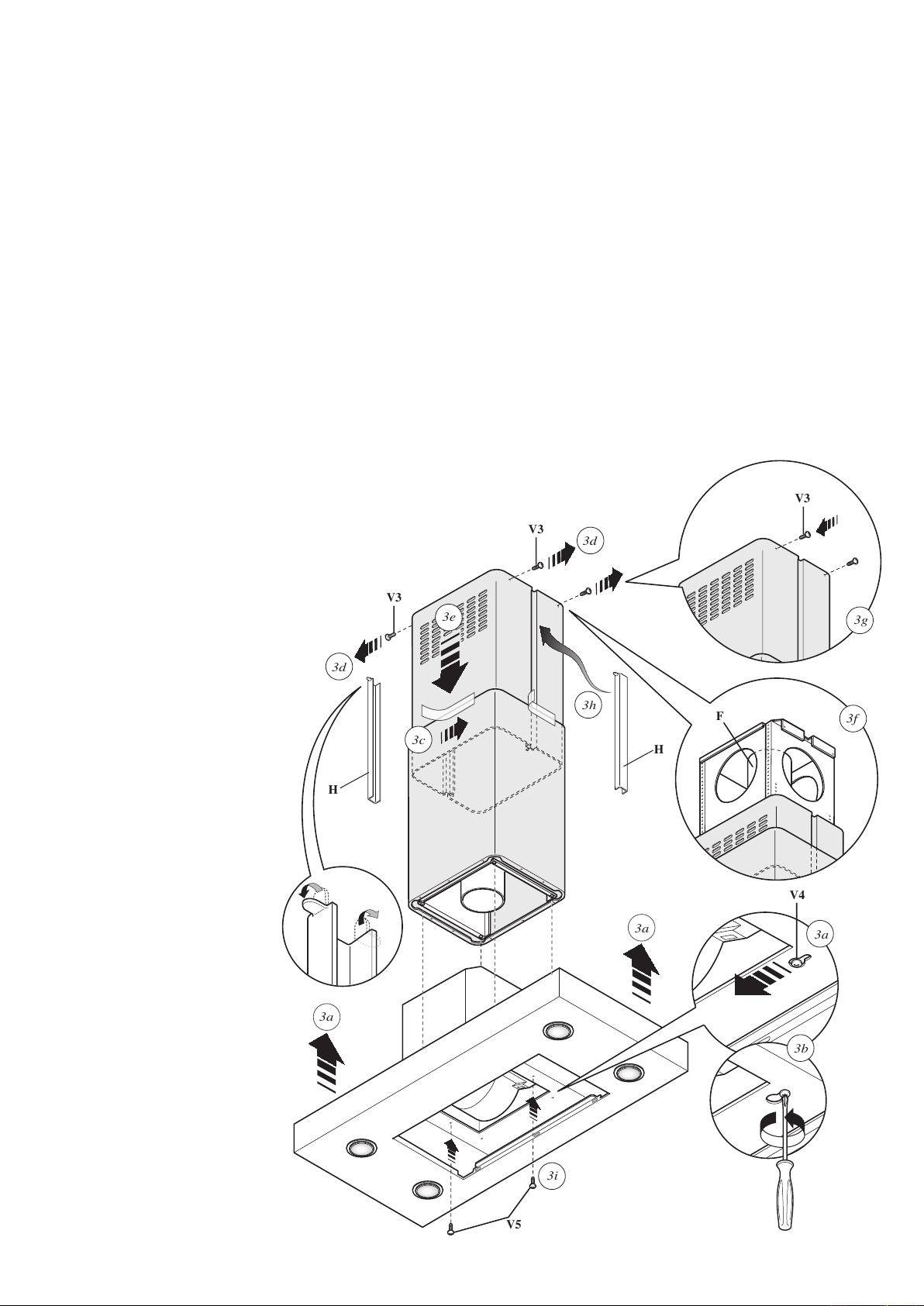
Fase 3/Phase 3/Fase 3/Phase 3
-
Alzare la cappa agganciandola alle 4 viti metriche M5 (V4) pre-avvitate al traliccio (C) (centrare i fori Ø11 sullʼasola dellʼintercamera e traslarla lateralmente) (Fig. 3a).
- Serrare definitivamente le 4 viti M5 (V4) (Fig. 3b).
- Togliere lo scotch di carta (Fig. 3c), togliere le 4 viti metriche M4 (V3) avvitate precedentemente sul traliccio (Fig. 3d) e far scorrere verso il basso lʼassieme camino-
prolunga (Fig. 3e).
- Eseguire il collegamento del tubo al raccordo del foro di scarico del soffitto (nel caso di versione aspirante) (Fig. 3f).
- Eseguire il collegamento elettrico solo dopo aver disinserito lʼalimentazione elettrica.
- Fissare la prolunga al traliccio (C) tramite le 4 viti metriche M4 (V3), senza bloccarle definitivamente (Fig. 3g).
- Tagliare a misura i copri-fessura (H) ed inserirli (Fig. 3h).
- Bloccare definitivamente la prolunga sul traliccio (C) serrando le 4 viti metriche M4 (V3).
- Bloccare il camino tramite 2 viti autofilettanti (V5) (Fig. 3i).
- Utilizzare gli elementi supporto prolunga (A) (Fig. 2) solo nel caso non venga usato il traliccio superiore, oppure nel caso di un contro-soffitto.
-
Raise the hood, hooking it onto the 4 M5 metric screws (V4) pre-tightened to the lattice-work (C) (center the Ø11 holes on the slot of the inner liner and move it laterally)(Fig. 3a).
- Completely tighten the 4 M5 screws (V4) (Fig. 3b).
- Remove the masking tape (Fig. 3c), remove the four M4 metric screws (V3) previously tightened onto the lattice-work (Fig. 3d) and slide the flue-extension assembly
downwards. (Fig. 3e).
- Connect the pipe to the connection of the ceiling discharge hole. (Fig. 3f).
- Make electrical connections only after having removed electrical power supply.
- Fasten the extension to the lattice-work (C) by means of the 4 M4 metric screws(V3), without tightening them completely(Fig. 3g).
- Cut to size the slot-covers (H) and insert them (Fig. 3h).
- Block the extension completely to the lattice-work (C) by screwing down the 4 M4 metric screws (V3).
- Block the flue with the 2 self-threading screws (V5) (Fig. 3i).
- Use the extension support elements(A) (Fig. 2) only if the upper lattice-work is not used, or in the case of a false ceiling.
- Levantar la campana sujetándola en los 4 tornillos métricos M5 (V4) previamente enroscados en el bastidor (C) (centrar los agujeros Ø11 respecto al orificio ovalado
del intersticio y desplazarla lateralmente) (Fig. 3a).
- Apretar definitivamente los 4 tornillos M5 (V4) (Fig. 3b).
- Quitar el papel adhesivo (Fig. 3c), sacar los 4 tornillos métricos M4 (V3) enroscados con anterioridad
en el bastidor (Fig. 3d) y deslizar hacia abajo el conjunto chimenea-elemento de prolongación
(Fig. 3e).
- Empalmar el tubo al racor del orificio de evacuación en el techo (en caso de versión
extractora) (Fig. 3f).
- Realizar la conexión eléctrica sólo después de haber desconectado la
alimentación eléctrica.
- Fijar el elemento de prolongación en el bastidor (C) por
medio de los 4 tornillos métricos M4 (V3), sin apretarlos
definitivamente (Fig. 3g).
- Cortar a medida los tapajuntas (H) e incorpo-
rarlos (Fig. 3h).
- Fijar definitivamente el elemento de pro-
longación en el bastidor (C) apretando los
4 tornillos métricos M4 (V3).
- Sujetar la chimenea por medio de 2 tornillos
autorroscantes (V5) (Fig. 3i).
- Utilizar los soportes del elemento de pro-
longación (A) (Fig. 2) sólo si no se utiliza
el bastidor superior, o también en caso de
falso techo.
- Die Dunstabzugshaube anheben und in die
4 bereits am Hängegerüst (C) angebrachten
metrischen Schrauben M5 (V4) einhängen
(dazu die Bohrlöcher Ø11 am Knopfschlitz
des Zwischenraums gerade ausrichten und
die Abzugshaube seitlich verschieben) (Abb.
3a).
- Nun die 4 Schrauben M5 (V4) endgültig
festziehen (Abb. 3b).
- Das Papierklebeband entfernen (Abb. 3c), die 4
vorher am Hängegerüst angebrachten metri-
schen Schrauben M4 (V3) entfernen (Abb.3d)
und die Einheit Kamin-Verlängerungsstück
nach unten gleiten lassen (Abb.3e).
- Den Anschluss des Rohrs am Anschluss der
Abzugsöffnung in der Decke durchführen
(bei Version mit Abluftbetrieb) (Abb. 3f).
- Die Stromversorgung unterbrechen und den
Elektroanschluss durchführen.
- Das Verlängerungsstück mit den 4 metrischen
Schrauben M4 (V3) am Hängegerüst (C)
befestigen, ohne die Schrauben ganz festzu-
ziehen (Abb. 3g).
- Die Ritzenabdichtungen (H) auf das genaue
Maß zuschneiden und einsetzen (Abb. 3h).
- Das Verlängerungsstück durch das Fe-
stziehen der Schrauben M4 (V3) endgültig
am Hängegerüst (C) blockieren.
- Den Kamin mit 2 gewindeformenden
Schrauben (V5) befestigen (Fig. 3i).
- Die beiden Stützelemente des Verlängerungs-
stücks (A) (Abb. 2) nur dann verwenden, wenn
kein oberes Hängegerüst eingesetzt wird oder
wenn eine Zwischendecke vorhanden ist.
V4
V5
V3
V3
F
3a
3a
3i
3a
3b
3d
3h
3d
3c
3e
3f
3g
V3
H
H