

Notes
The Manual defines the agreements between SAIC GM Wuling Automobile Co., Ltd. ① and
Owners on establishment and termination of related product quality assurance liabilities, after-
sales rights and duties. It helps you understand how to use and maintain the vehicle correctly,
and it is a basis for your quality assurance service. Please always read the Manual carefully
before using our products.
Service & Maintenance and Owner’s Manual of Baojun 530
Thank you for choosing the vehicle manufactured elaborately by SGMW.
SAIC GM Wuling Automobile Co., Ltd.
Jan. 2018
①: In the Manual, SAIC GM Wuling Automobile Co., Ltd. is called SGMW or the Company for short.


SGMW Three-guarantees Certificate Coupon A
Product information
Product brand: Baojun
Model:
Vehicle type: multi-purpose passenger car
Vehicle specification: K31
Vehicle identification number (VIN): LZW_ _ _ _ _ _ _ _ _ _ _ _ _ _ _ _ _ _ _ _ _ _ _ _ _ _ _
Manufacturer information
Name: SAIC GM Wuling Automobile Co., Ltd.
Post code: 545007
Add.: 18th Hexi Road, Liuzhou, Guangxi, P.R.China
Service Tel.: 400-86-12345, 400-889-5050
Seller information (stamp)
Name:
Post code:
Tel.:
Add.:
Sales date: MM DD YY
Three-guarantees clauses (count from the invoice date or the current driving mileage, whichever comes first)
Warranty period of automobile product: 3 years or 60,000 km for whole vehicle
Three-guarantees validity of automobile product: 2 years or 50,000 km for whole vehicle
Other Three-guarantees commitments: Please refer to Appendix 1 of the Three-guarantees Certificate for the range of whole vehicle parts and components and Appendix 2 of the Three-guarantees Certificate for the range and quality assurance
period of vulnerable parts and components and the range of powertrain parts that enjoy warranty of 5 years or 100,000 km. As for other warranty policies and clauses, please refer to the main body of the Manual.
Owner information
Buyer information: Natural person Legal person
Name:__________________Tel.:__________________ID/unit contact:__________________
Add.: __________________(detailed address)___________(city/county)___________(province/municipality) Owner’s signature:_____________
Note: The Three-guarantees Certificate Coupon A shall be kept by the dealer and the Three-guarantees Certificate Coupon B shall be kept by the owner; for information not detailed, the Manual
shall prevail.


SGMW Three-guarantees Certificate Coupon B
Product information
Product brand: SGMW
Model:
Vehicle type: multi-purpose passenger car
Vehicle specification: K31
Vehicle identification number (VIN): LZW_ _ _ _ _ _ _ _ _ _ _ _ _ _ _ _ _ _ _ _ _ _ _ _ _ _ _
Manufacturer information
Name: SAIC GM Wuling Automobile Co., Ltd.
Post code: 545007
Add.: 18th Hexi Road, Liuzhou, Guangxi, P.R.China
Service Tel.: 400-86-12345, 400-889-5050
Seller information (stamp)
Name:
Post code:
Tel.:
Add.:
Sales date: MM DD YY
Three-guarantees clauses (count from the invoice date or the current driving mileage, whichever comes first)
Warranty period of automobile product: 3 years or 60,000 km for whole vehicle
Three-guarantees validity of automobile product: 2 years or 50,000 km for whole vehicle
Other three-guarantees commitments: Please refer to Appendix 1 of the Three-guarantees Certificate for the range of whole vehicle parts and components and Appendix 2 of the Three-guarantees Certificate for the range and quality assurance
period of vulnerable parts and components and the range of powertrain parts that enjoy warranty of 5 years or 100,000 km. As for other warranty policies and clauses, please refer to the main body of the Manual.
Owner information
Buyer information: Natural person Legal person
Name:__________________Tel.:__________________ID/unit contact:__________________
Add.: _____________(detailed address)_____________(city/county)_____________(province/municipality) Owner’s signature:_____________
Note: The Three-guarantees Certificate Coupon A shall be kept by the dealer and the Three-guarantees Certificate Coupon B shall be kept by the owner; for information not detailed, the Manual
shall prevail.


SGMW Three-guarantees Certificate Appendix 1
Assembly
Main part
SGMW explanation
Engine
Crankshaft
Crankshaft
Main bearing
Crankshaft main bearing, bearing bushing and thrust
bearing
Connecting rod
Connecting rod assembly and component
Connecting rod bearing
Connecting rod bushing, connecting rod bearing shell and
connecting rod bearing
Piston
Piston and piston assembly
Piston ring
Piston ring
Piston pin
Piston pin
Cylinder head
Cylinder head body
Camshaft
Intake camshaft and exhaust camshaft
Valve
Intake valve and exhaust valve
Cylinder block
Cylinder block body
Transmission
Housing
Transmission housing, clutch housing, rear cover, rear
housing;
Gear
Drive gear in transmission; differential in transmission
Shaft
Propeller shaft in transmission
Bearing
Propeller shaft bearing in transmission
Power drive elements in transmission
(incl. clutch, brake)
Synchronizer; clutch disc, clutch friction plate, chain and
sprocket of automatic transmission
Steering system
Steering gear assembly
Mechanical, hydraulic and electric steering gear
Steering column
Steering column
Steering universal joint
Intermediate steering shaft assembly and steering propeller
shaft
Assembly
Main part
SGMW explanation
Steering linkage (excl. ball)
Steering gear inner tie rod and outer tie rod service kit
Knuckle
Knuckle
Brake system
Brake master cylinder
Brake pump assembly, brake master cylinder assembly
and brake master cylinder service kit
Wheel cylinder
Rear wheel cylinder, brake wheel cylinder, front brake
caliper and rear brake caliper
Booster
Vacuum booster assembly and brake master cylinder
booster
Brake pedal and bracket
Brake pedal and pedal bracket
Front/rear axle
Axle housing
/
Main reducer and differential
/
CV joint
CV joint, constant velocity joint and drive shaft
Propeller shaft
/
Suspension
system
Spring
Various springs, front stabilizer and stabilizer connecting
rod
Control arm
Front lower rocker arm, swing arm and ball pin assembly,
control arm, front lower longitudinal rail and tie rod
assembly
Connecting rod
Rear axle assembly and twist beam assembly
Body
Body frame
BIW assembly
Subframe
Subframe, engine support and transmission support
Longitudinal rail
Front/rear longitudinal member, side rail, longitudinal floor
rail and sill beam inner plate
Crossmember
Front/rear crossmember and floor crossmember
Front and rear doors
Front/rear doors and liftgate
SGMW Three-guarantees Certificate Appendix 2
Range and quality assurance period of vulnerable parts and components
Vulnerable parts and components
Quality assurance period
Warranty period
Three-guarantees validity
Air cleaner element, air conditioner filter element, oil filter, fuel filter, tire, wiper blade, fuse and common relay (excl. integrated control unit)
3 months or 5,000 km
None
Brake lining, spark plug, (manual) clutch friction plate, bulb, remote control battery
6 months or 10,000 km
Battery
12 months or 20,000 km
Range of powertrain parts that enjoy warranty of 5 years or 100,000 km
Engine: cylinder block, cylinder head, crankshaft, connecting rod, valve guide pipe, camshaft, oil pump, timing sprocket, timing chain, timing belt pulley, intake/exhaust manifold, piston, oil pan, camshaft/crankshaft bearing cap, flywheel
Manual transmission: housing, gears, shafts, synchronizer, shift fork/lever
Compensation coefficient and calculation formula of returned/replaced vehicle: [(vehicle price (RMB) × total mileage (km))/1000] × 0.8%
Range of special parts and components customized as per vehicle identification number (VIN): none

Contents 1
Contents
Preface ..................................................................... 2
Keys, Doors and Windows ....................................... 5
Seats and Protective Devices ................................. 23
Storage ................................................................... 42
Instruments and Controls ....................................... 49
Lighting ................................................................... 85
Driver Information and Entertainment ..................... 91
HVAC ...................................................................... 95
Driving and Controls ............................................. 109
Vehicle Service & Maintenance ............................ 125
Technical Data ...................................................... 162
Accessory List ....................................................... 177
Maintenance Procedures ...................................... 180
2 Preface
Preface
The vehicle is integrated with advanced technologies,
safety, environmental protection and economy.
The Manual provides necessary information to help you
drive your vehicle safely and effectively.
The driver shall always note that improper operation of
vehicle may cause accidents and injury risks. Moreover, you
shall comply with the requirements in laws and regulations
of the country. If these requirements are different from those
in the Manual, the requirements in the laws and regulations
shall prevail.
The staff of SGMW Aftersales Service Center
②
all received
professional trainings and can provide complete and
satisfactory service for you. Please contact a nearby
Service Center if you vehicle needs maintenance or repair.
Please refer to the Subsection “Inquiry Way of Aftersales
Service Center Contact” in the Section “Maintenance
Procedures” for details of Service Center Contact.
Please carry the Manual with your vehicle for review and
reference at any time. If you want to resell the vehicle,
please hand the Manual over to the new owner along with
the vehicle for use by the new owner when needed.
How to Use the Manual
The contents at the beginning of the Manual and each
section are used for locating specific information.
As for directional data such as front, rear, left and
right, the driving direction shall be taken as the front.
Some functions described in the Manual may not be
configured for all models, and the Manual may
introduces some devices/functions that are not
installed on your vehicle.
The Manual includes the latest information available
at the time of printing the Manual. The Company has
the full authorities to take charge of the amendment
to and statements on the Manual and reserves the
right to make changes to the product without further
notice after the Manual is printed. Some of pictures in
the Manual are illustrations only for your reference.
Please refer to real objects if pictures are not
consistent with real objects.
Prompts
Note
The content marked with “Note” indicates matters
need to be noted during vehicle operation. Ignoring
such information may lead to wrong operation.
Warnings
The content marked with “Warnings” indicates risks
of accidents or injuries. Ignoring such information
may lead to injuries.
Caution
The content marked with “Caution” indicates
possibility of vehicle damage. Ignoring such
information may lead to vehicle damage.
Dangers
The content marked with “Dangers” indicates risks of
fatal injuries. Ignoring such information may endanger
lives.
“*”: asterisk behind a title or text
“*” indicates that the equipment mentioned is optional, and
your vehicle may not have such equipment. Please refer to
the actual vehicle for vehicle configuration.
SAIC GM Wuling Automobile Co., Ltd. reserves the
copyright of the Manual.
②: In the Manual, the Aftersales Service Center of SAIC GM Wuling Automobile Co., Ltd. is called Aftersales Service Center or Service Center for short.

Quick Guide 3
Quick Guide
● Remote Control .......................................................................................................... 7
● Passive Entry Passive Start (PEPS) System* .......................................................... 13
● Outside Rearview Mirror .......................................................................................... 15
● Windows .................................................................................................................. 17
● Sunroof* ................................................................................................................... 19
● Child Seat ................................................................................................................ 33
● Air Bag System ........................................................................................................ 35
● Instrument Panel ...................................................................................................... 50
● Warning Lamps, Gauges and Indicators .................................................................. 55
● Reverse Sensor* ...................................................................................................... 82
● Parking Assist System* ............................................................................................ 84
● Outside Lighting ....................................................................................................... 86
● Air Conditioning........................................................................................................ 98
● Start and Operation ................................................................................................ 111
● MT Transmission * ................................................................................................. 117
● Brake ..................................................................................................................... 118
● Fuel ........................................................................................................................ 123
● Wheels and Tires ................................................................................................... 147
● Jump Start (Dead Battery) ..................................................................................... 154
● Vehicle Traction ..................................................................................................... 155
● Vehicle Data........................................................................................................... 165
● Accessory List ........................................................................................................ 178
● Warranty ................................................................................................................ 182
● Maintenance .......................................................................................................... 186
Prompt: The content in this part is the most fundamental to ensure safe and comfortable driving by you. Please ask the sales consultant who delivers the vehicle to you to explain this part clearly
to get the required knowledge and skills.


Keys, Doors and Windows 5
1
Keys, Doors and Windows
Keys, Doors and Windows
Keys .................................................................................. 6
Key-in Reminder* ..................................................... 7
Remote Control ................................................................. 7
Vehicle Locating ....................................................... 7
Remote Window Lowering ....................................... 7
Remote Opening/Closing of Panoramic Sunroof* .... 7
Activation of Door Lock and Anti-theft Mode ............ 7
Door Unlock and Release of Anti-theft Mode ........... 8
Lock Function Alarm ................................................ 8
Door Lock .......................................................................... 9
External Door Locking and Unlocking ...................... 9
Child Safety Lock ................................................... 11
Central Door Lock System ..................................... 12
Door Lock Thermal Protection ............................... 12
Doors ............................................................................... 12
Liftgate ................................................................... 12
Passive Entry Passive Start (PEPS) System* ................. 13
Passive Entry ......................................................... 13
Passive Locking ..................................................... 13
Passive Unlocking/Locking of Liftgate .................... 14
Engine Hood .................................................................... 14
Opening Engine Hood ............................................ 14
Closing Engine Hood ............................................. 15
Outside Rearview Mirror .................................................. 15
Adjusting Outside Rearview Mirror ......................... 15
Electrically Folding Outside Rearview Mirror* ........ 16
Automatically Folding Outside Rearview Mirror* .... 16
Folding ................................................................... 16
Defrosting of Outside Rearview Mirror* .................. 16
Inside Rearview Mirror ..................................................... 17
Windows .......................................................................... 17
Power Window ....................................................... 17
Sunshade ........................................................................ 18
Auxiliary Handrail ............................................................ 19
Sunroof* .......................................................................... 19
Power Sunroof* ...................................................... 19
Panoramic Sunroof* ............................................... 20
6 Keys, Doors and Windows
Keys
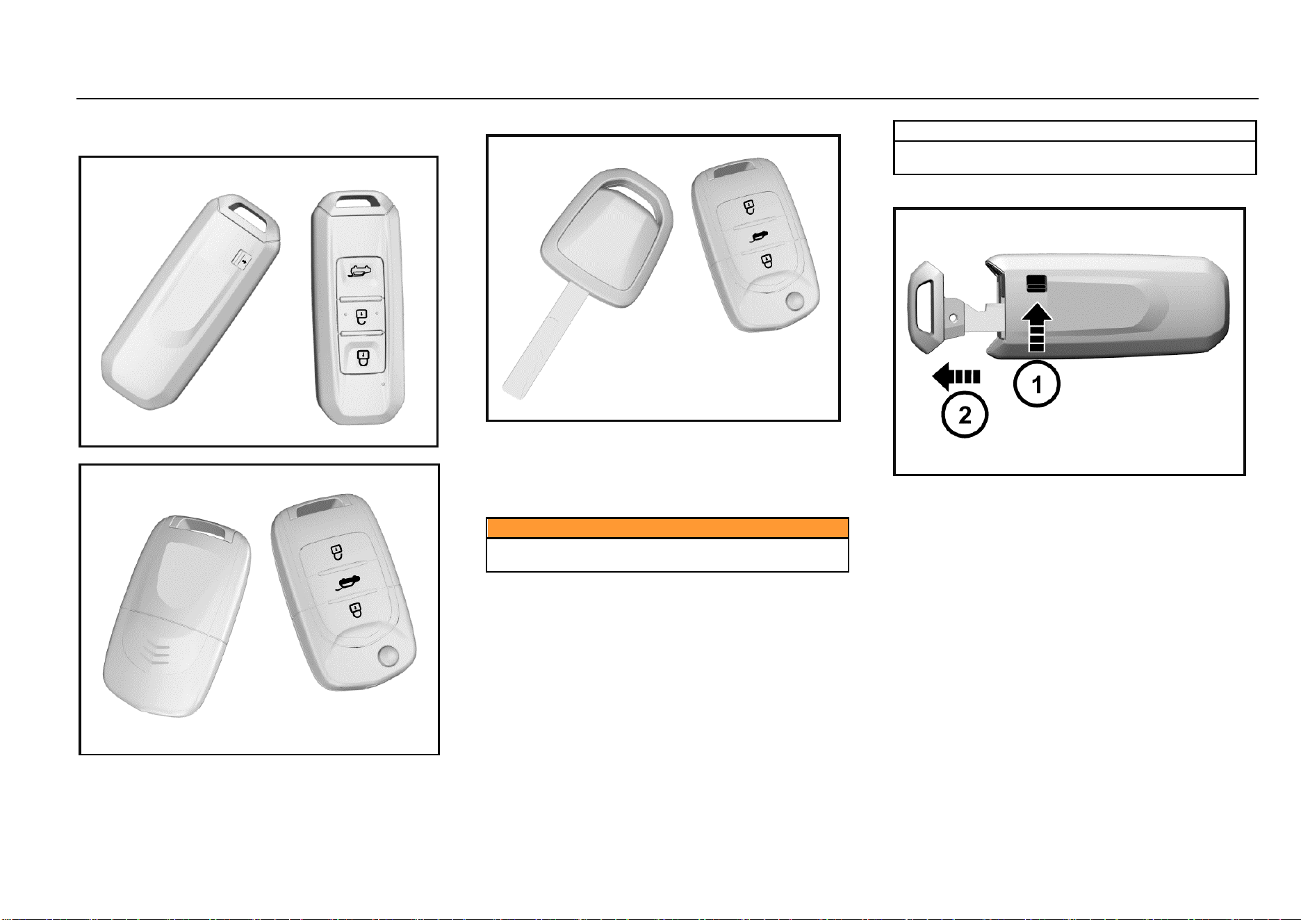
Type I
Type II
Type III
Each new vehicle is provided with two keys. Please reserve
one key for spare.
For the sake of safety, please keep the key number plate in
a safe place to prevent from illegal key making.
Different models may be provided with different keys.
Please refer to real vehicles.
Caution
Do not leave the key in the vehicle. Take the key with
you when you leave the vehicle.
Note
If the key is lost, please contact with the Aftersales
Service Center.
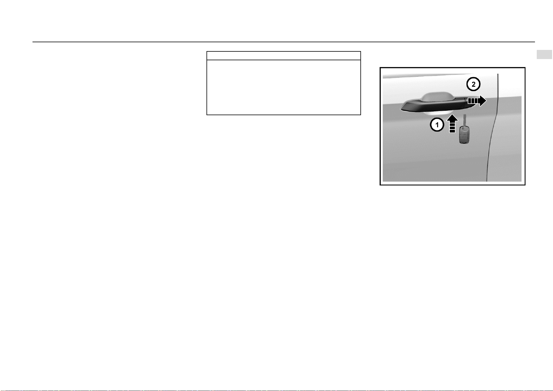
Detachable Type
As shown in the figure above, turn the release switch ① on
the key first, and then pull out the mechanical key ②.
Plug back the mechanical key after use.
Keys, Doors and Windows 7
1
Keys, Doors and Windows
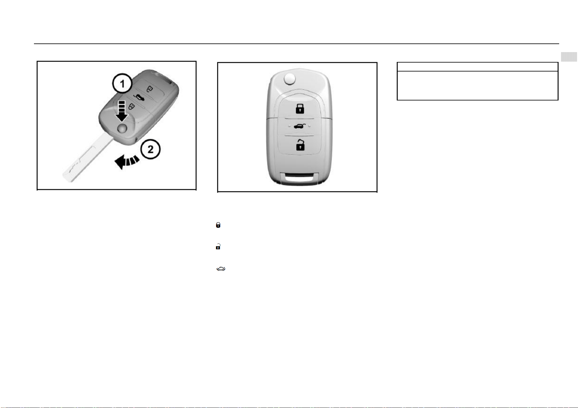
Foldable Type
As shown in the figure, press the release button, and the
mechanical key will pop up automatically.
Fold the mechanical key after use.
Key-in Reminder*
If the driver’s door is opened when the ignition key is at
LOCK position and is not pulled out, the instrument will ring
for prompt. The function reminds you to take the key with
you when you leave the vehicle.
Remote Control
The effective distance of remote control is about 15 m
without shielding. When the ignition key is plugged in the
switch or the ENGINE START STOP Switch is at ACC or
ON position, the remote control does not function.
: remote lock button. Press the button once to lock all
doors after all doors are closed; the hazard warning lamp
will flash twice, and the vehicle is at anti-theft state.
: remote unlock button. Press the button once to unlock all
doors; the hazard warning lamp will flash once, and the anti-
theft state is released.
: liftgate unlock button. Press and hold for about 2s;
open the liftgate, and the hazard warning lamp will flash
once.
Note
The functioning range of the remote control may be
different due to environmental reasons. Radio
interference signals and barriers will affect the remote
control functions.
Vehicle Locating
Press the remote unlock button quickly for two times to
activate the vehicle locating function, and the hazard
warning lamp will flash for 20 times.
Remote Window Lowering
Press and hold the unlock button for about 2s to lower all
windows automatically and in turn.
Remote Opening/Closing of Panoramic
Sunroof*
If the vehicle is configured with a panoramic sunroof, press
the unlock button/lock button of the remote control for about
2s, the sun blind and sunroof will be opened/closed
automatically.
Activation of Door Lock and Anti-theft Mode
1. Close all the windows.
2. Turn the ignition key to LOCK position and pull out the
key (if mechanical ignition key is configured).
3. All passengers leave the vehicle.
4. Close all doors and the engine hood.
8 Keys, Doors and Windows
5. Press and release the remote lock button. All doors
are locked. The hazard warning lamp will flash twice,
and the immobilizer is activated.
As for a vehicle configured with ENGINE START STOP
function, only when the ignition switch is at LOCK position
can the transmitter activates the immobilizer system.
Note
The anti-theft mode must be activated with the
transmitter.
Warning sound
Under the anti-theft state, when the unlock button on the
transmitter is not pressed and any of the doors or liftgate is
forced opened in an abnormal way (including use of a key),
the system will make the hazard warning lamp flash and
emit warning sound.
To stop warning sound
Press and hold the lock, unlock or liftgate button on the
transmitter for about 2s or turn the key to ON position to top
the warning sound; if not, the warning sound will be ended
automatically after 30s, and the anti-theft mode is activated
again. If the system fails to do so, it is recommended to have
the system checked by the Aftersales Service Center.
Door Unlock and Release of Anti-theft Mode
1. Press the unlock button on the remote control once.
All doors are unlocked.
The hazard warning lamp flashes once.
The anti-theft state is released.
2. Press and hold the liftgate open button for 2s.
The liftgate is opened.
The hazard warning lamp flashes once.
The anti-theft state is released.
Lock Function Alarm
The horn will buzz thrice ad the hazard warning lamp will
flash thrice to indicate that the doors are not locked
successfully if the remote lock button is pressed or passive
locking is conducted when the door lock conditions are not
met. These situations include:
1. There is a door not closed (including liftgate);
2. The door lock is under thermal protection;
3. The ignition switch is not at the LOCK position;
4. The passive entry system (if configured) detects a
legal key in the vehicle.
Caution
Never leave a child or pet unattended in the vehicle.
Otherwise, it may cause injuries or death due to high
temperature in the vehicle.
Automatic Locking of Door
When all doors are closed and the vehicle speed exceeds
10 km/h, all doors will be locked automatically.
Automatic Re-locking
With the key not in the ignition switch, the vehicle will
activate re-locking if the alarm is disarmed but any of the
doors and liftgate is not opened within 30s after the vehicle
is under the armed state successfully.
Ignition OFF Unlocking
When the doors are locked, they will be unlocked
automatically if the ignition switch is turned from ON position
to ACC or LOCK position.
Remote Control
Each remote control has its own electronic code to prevent
the doors being opened with other remote controls.
If the remote control is lost or stolen, please contact the
Aftersales Service Center to buy a new one as soon as
possible. If you need to replace one or more remote
controls, please bring with the existing remote control(s)
when you go to the Aftersales Service Center. When the
Aftersales Service Center matches the remote control for
replacement with the vehicle, the existing remote control
shall also be matched with the new code. After the new
remote control is coded electronically, the lost remote
control will not unlock your vehicle. For Type I key, 3
transmitters can be configured at most each time; for Type
II and III keys, 4 transmitters can be configured at most each
time.
Keys, Doors and Windows 9
1
Keys, Doors and Windows
Signal Transmission Autostop Function of Remote
Control
The remote control has the signal transmission autostop
function which can prevent unnecessary battery loss
caused by misoperation and other reasons.
Long press any button on the remote control for over 10s,
the remote control will stop transmitting signals
automatically.
If the button is released, the signal transmission autostop
function is deactivated.
Fault
If the remote control cannot function normally, it may be
caused by the following reasons:
Out of remote control working range;
Excessively low remote control battery;
Interference by external environment and other high-
power radio signals (such as base station and launch
tower);
Signal blocking by other barriers.
Battery Replacement
Inside the key remote control, there is a lithium battery
whose service life is 2 years generally. When the remote
control distance is shortened gradually (i.e. must get closer
to the vehicle), it indicates a low battery. The key battery
cannot be charged. After the battery runs out, please go to
the Aftersales Service Center to have the battery changed.
Battery model: CR2032.
Note
To ensure normal functioning of the remote control,
please follow the following rules:
● Avoid dropping the remote control.
● Please do not place a heavy object on the remote
control.
● Make sure the remote control is away from water or
direct sunlight. If the remote control is socked, please
wipe with soft cloth.
Door Lock
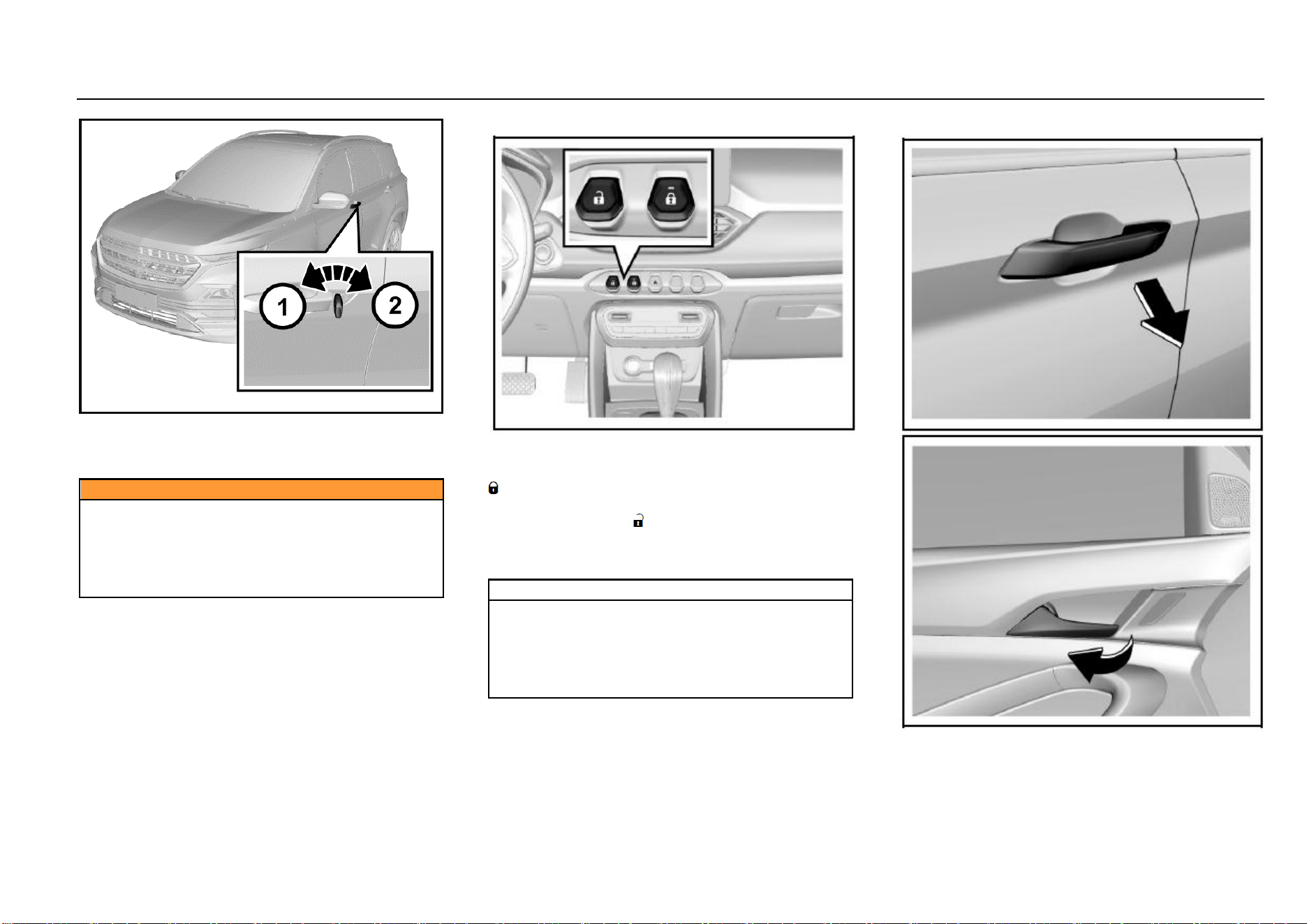
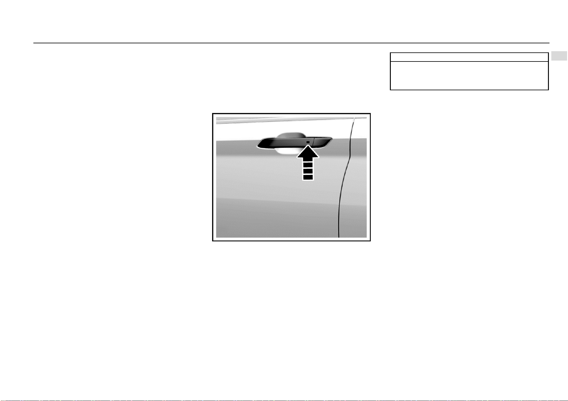
External Door Locking and Unlocking
As shown in the figure above, the lockhole on the left front
door external handle is hidden under the trim cover. The trim
cover needs to be removed first if the key is used to open
the door; for example, the remote control is lost or out of
power.
Below the trim cover, there is a small hole. Plug the key in
the hole and press inward; at the same time, prize up the
trim cover outward to remove the cover.
For installation, press the trim cover inward to fasten it.
10 Keys, Doors and Windows
To lock a door outside of the vehicle with a key, plug the key
and rotate it clockwise. Rotate the key couterclockwise to
unlock the door.
Caution
Do not leave a child or pet alone in the vehicle.
Otherwise, severe casualty will be caused. The child
may operate power windows or other control buttons
or even drive the vehicle.
Do not leave the child with a key in the vehicle. Such
behaviors may cause severe casualties.
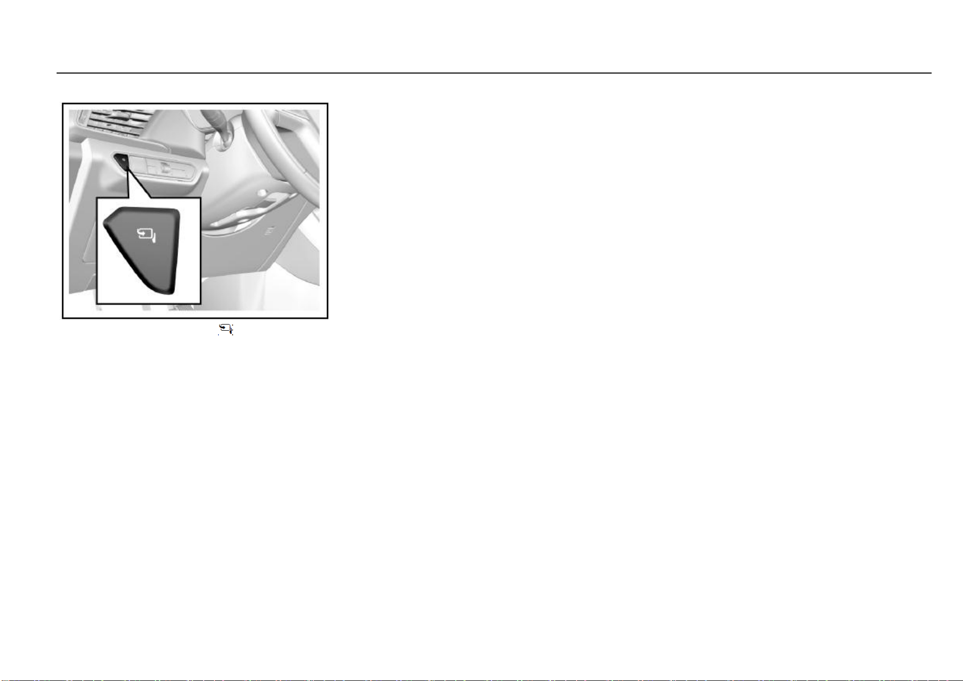
Internal Door Locking and Unlocking
As shown in the figure, a central door lock switch is set on
the middle of the instrument panel. To lock doors from
inside, press the lock button on the central door lock switch
.
To unlock doors from inside, press the unlock button on the
central door lock switch .
If the lock button indicator is on, it means the doors are
locked; if the indicator is off, it means the doors are
unlocked.
Note
When you leave the vehicle unattended, you must lock
all doors and liftgate and take the key with you. If the
doors and liftgate are unlocked, the vehicle may be
stolen. Please park your vehicle in an attended place.
It is recommended not to leave valuables in the vehicle
to prevent losses due to unforeseen circumstances.
External/Internal Door Opening
To open doors from inside or outside, unlock the doors first,
and pull the external or internal door handles.
Keys, Doors and Windows 11
1
Keys, Doors and Windows
When the doors are locked, pulling the internal door handle
twice can open the doors.
A child shall sit on the rear seat, and the door shall be locked
with the child safety lock.
Note
If there is noise while opening/closing doors or
driving, apply lubricating grease on the door catches
and hinges.
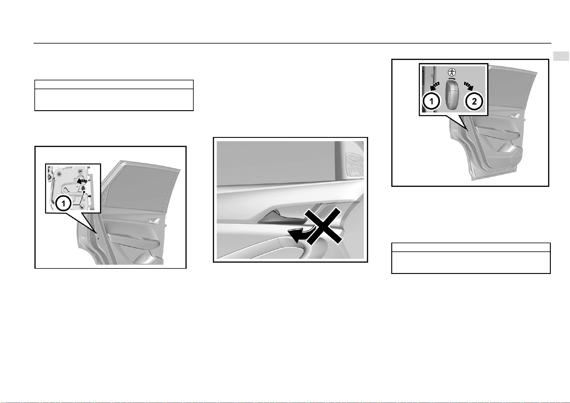
Door Locking Method in Case of Vehicle Outage
In case of vehicle outage (for example, the battery is out of
power or its positive and negative poles are disconnected),
the central door lock system does not function, and you
need to lock side doors manually one by one.
As shown in the figure above, open the right front door and
two rear doors, and find the internal knobs of locks (not the
knob of child safety lock).
Rotate the knobs outward with a key, and close the doors.
At last, pull the external handles to ensure that the doors are
locked. At this time, please pull the internal handle once first
if you want to open the door.
For the left front door, please plug the key in the external
door handle and rotate the key clockwise to lock the door.
Please refer to the content in the Subsection “External Door
Locking and Unlocking”.
Child Safety Lock
The rear doors are equipped with child safety locks.
The function of the child safety lock is to prevent passengers
(especially children) from pulling the door handle to open
the rear door.
To activate the child safety lock:
1. Open the rear door that you want to lock.
2. Find the child safety lock hole on the door edge and
near the middle position.
3. Plug the key and rotate clockwise to the lock position.
When the child safety lock is activated, you need to pull the
external door handle to open the door. To deactivate the
child safety lock, please plug the key and rotate
couterclockwise to the unlock position.
Note
The two rear doors are equipped with a child safety
lock respectively. They function separately and must
be activated manually and respectively.
12 Keys, Doors and Windows
Note
When the child safety lock is activated, do not attempt
to pull the internal door handle to open the door.
Otherwise, the door handle may be damaged.
Central Door Lock System
The central door lock system enables you to lock and unlock
all doors with the remote control or the central door lock
switch from inside.
Door Lock Thermal Protection
If the doors are unlocked/locked for over 10 times within 8s,
the locks will be prohibited for 10s to protect them.
Doors
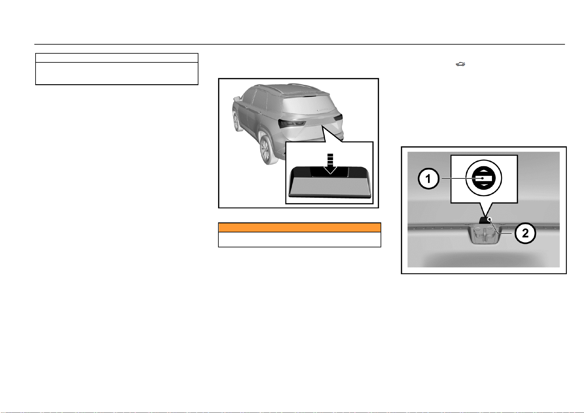
Liftgate
Liftgate Release Switch
As shown in the figure, the liftgate release switch is above
the liftgate release handle.
Caution
Before driving, please make sure that the liftgate is
closed and locked.
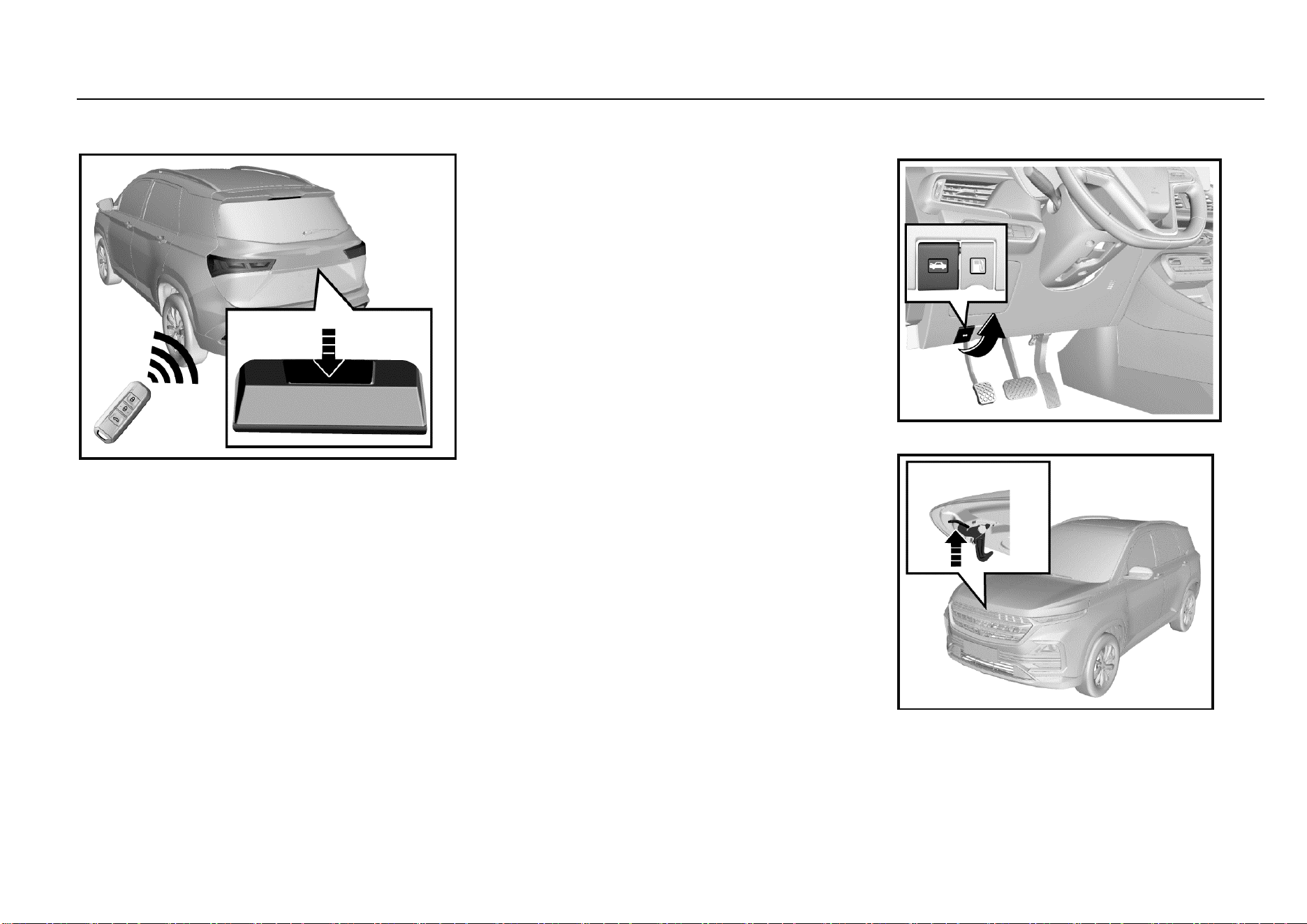
Liftgate Opening
The liftgate can be opened in 3 ways:
1. Unlock doors first, and then press the liftgate release
switch to open the liftgate.
2. Press the liftgate open button on the remote control
key for about 2s to open the liftgate.
3. For vehicles equipped with passive entry passive start
(PEPS) system, bring with the key and get close to
the liftgate, and the liftgate can be opened by pressing
the liftgate release switch.
Make sure that you and other persons are out of the liftgate
moving range to prevent personal injuries when the liftgate
is popped open.
To lock the liftgate, you need to close it and then lock it.
Make sure that your or other persons’ hands and bodies are
out of the closing rage of the liftgate.
Liftgate Opening from Inside of Luggage Compartment
If other liftgate opening methods are invalid, the liftgate can
be opened temporarily as per the following steps:
Keys, Doors and Windows 13
1
Keys, Doors and Windows
1. Fold the rear seat backrests, and get to the luggage
compartment.
2. Prize up the trim cover outside the liftgate lock, and
there is a slotted knob.
3. Plug a screwdriver or a key in the slot, and rotate the
knob clockwise to open the liftgate.
Passive Entry Passive Start (PEPS)
System*
High-configured models are equipped with PEPS system.
You can lock or unlock the doors conveniently only by taking
the remote control key with you and getting to the certain
ranges of the front doors or liftgate. You can lock or unlock
remotely without taking your key out from your pocket.
Passive Entry
When the doors are locked and the ignition switch is at
LOCK position, bring a legal key and get close to the front
door handle (within 1.2 m); press the button on the handle,
and the system will certify with the key. Once certified
successfully, the system will unlock all doors. The hazard
warning lamp flashes once.
Note
If the remote control battery is low, the passive
entry/locking function may fail, and you can use the
mechanical key to lock/unlock doors. Please replace
the remote control battery as soon as possible.
Passive Locking
When all doors are closed and the ignition switch is at LOCK
position, bring a legal key and get close to the front door
handle (within 1.2 m); press the button on the handle, and
the system will certify with the key. Once certified
successfully, the system will lock all doors. The hazard
warning lamp flashes twice.
The system will send warning prompt, the horn will buzz
thrice and the hazard warning lamp will flash thrice to
indicate that the doors are not locked when you press the
button on the door handle in case of the following situations:
1. There is a door not closed;
2. The ignition switch is not at LOCK position;
3. There is a key in the vehicle.
Check one by one, and then lock again.
14 Keys, Doors and Windows
Passive Unlocking/Locking of Liftgate
Passive Unlocking
When the doors are locked and the ignition switch is at
LOCK position, bring a legal key and get close to the liftgate
(within 1.2 m); press the liftgate release switch, and the
system will certify with the key. Once certified successfully,
the system will unlock the liftgate, and the liftgate pops
open.
If the doors are already unlocked, the liftgate can be opened
by pressing the liftgate release switch directly (unnecessary
to bring the key and get close to the liftgate).
Passive Locking
If the doors are locked, when the liftgate is closed, the
system will search automatically whether there is a legal key
in the vehicle. If there is no legal key in the vehicle, the
liftgate will be locked automatically. The hazard warning
lamp flashes twice. If there is a key in the vehicle, the
system will send warning prompt, the horn will buzz thrice
and the hazard warning lamp will flash thrice; the four side
doors will be unlocked automatically. Please take away the
key in the vehicle, and lock the doors again.
If the doors are unlocked, the liftgate can only be locked
after closing the liftgate and locking the doors. Please
remember to lock the doors.
Engine Hood
Opening Engine Hood
1. Pull the engine hood release handle on the left lower
side of the instrument panel.
Keys, Doors and Windows 15
1
Keys, Doors and Windows
2. After the engine hood is opened slightly, stretch out
the hand to the lower side of the engine hood front
edge. Pull the engine hood release handle upward as
shown in the figure to open the engine hood
completely.
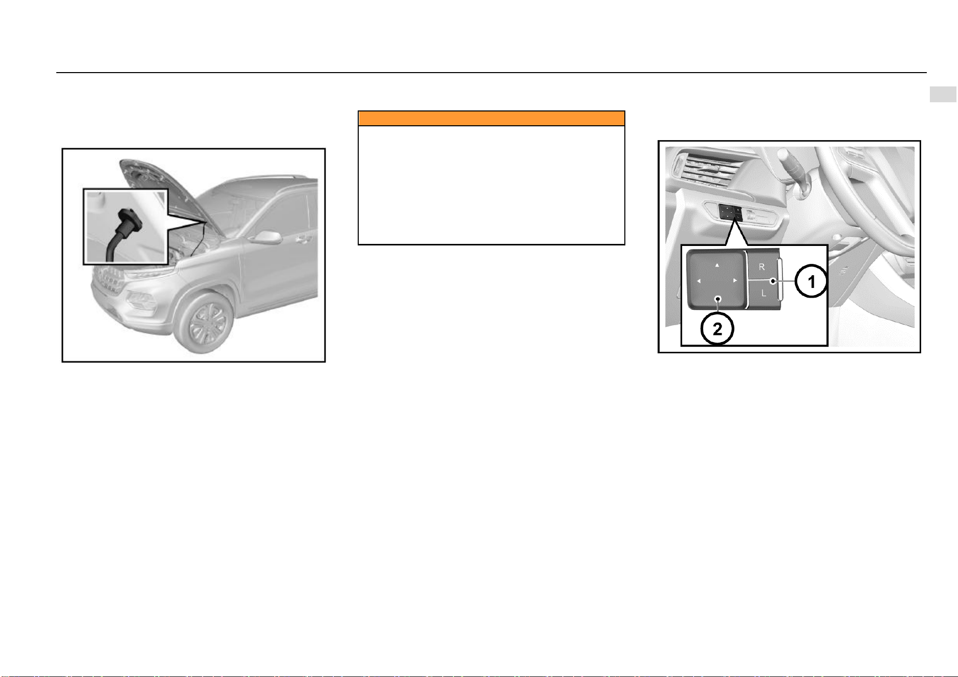
3. Separate the engine hood prop rod from the fixing
clamp. Plug the free end of the prop rod in the slot.
Closing Engine Hood
1. Support the engine hood to prevent it from closing,
and take the prop rod out from the slot. Then, fix the
rod in the fixing clamp.
2. Make sure that your or other persons’ hands or other
body parts are away from the engine compartment,
engine hood and vehicle body edges.
3. Slowly drop the engine hood, and release it when the
engine hood front edge is about 30 cm vertically from
the top crossmember of the water tank to let it fall
freely.
4. Always check and confirm that the engine hood is
locked in place.
Caution
● Pull the engine hood front edge before driving to
make sure that the engine hood is locked.
● Do not pull the engine hood release handle when the
vehicle is moving.
● Do not drive the vehicle when the engine hood is
open. If the engine hood is open, the driver’s sight will
be blocked.
Driving when the engine hood is open may cause a
collision accident, damaging your vehicle or other
properties or leading to casualties.
Outside Rearview Mirror
Please check the visual field of all rearview mirrors before
driving.
Adjusting Outside Rearview Mirror
The power outside rearview mirror adjustment switch is on
the left side of the instrument panel. Adjust the outside
rearview mirror as per the following steps:
1. Select the rearview mirror to be adjusted. Press the
“L” or “R” on the selector switch to adjust the left or
right outside rearview mirror.
2. Press the buttons (△) around the setting pan to adjust
the selected rearview mirror upward, downward,
leftward and rightward.
3. After adjustment, recover the selector switch to non-
pressed state (both ends not pressed).
16 Keys, Doors and Windows
Electrically Folding Outside Rearview Mirror*
Press the electric folding button to fold the outside
rearview mirror automatically.
Press the button once again, and the mirror will be unfolded
automatically.
Automatically Folding Outside Rearview Mirror*
The outside rearview mirror will be folded automatically
when the doors are locked. It will be unfolded automatically
when the doors are unlocked.
If the electric folding button is pressed, the outside rearview
mirror will not be unfolded automatically when the doors are
unlocked.
Deactivating Automatic Folding Function of Outside
Rearview Mirror*
In frosty weather, the outside rearview mirror and its spindle
may be frozen in folded state, and the mirror cannot be
unfolded. That will affect your driving. Therefore, we
suggest you deactivate the automatic folding function of the
outside rearview mirror temporarily in icy winter to let the
mirror maintained in unfolded state.
Method: Enter the audio setup interface, and set the
“Rearview Mirror Folding” to “OFF” under the “General
Setup” interface. Thus, the outside rearview mirror will not
be folded automatically when the doors are locked.
Notes to Electrical Folding of Frozen Outside Rearview
Mirror
If the outside rearview mirror and its spindle are frozen,
please remove the freeze first, and use the electric
folding/unfolding functions. For example, if the mirror is
frozen after the vehicle is parked outdoors for a night in
winter, please remove the freeze first, and use the remote
control or the passive entry button to unlock doors. Then,
the outside rearview mirror will be unfolded smoothly. If the
freeze is not removed, the freeze will hinder the movement
of the rearview mirror, damaging the mirror.
If the outside rearview mirror glass is frozen, please remove
the freeze first, and then use the defrosting function for
auxiliary heating and deicing. If the freeze is not removed,
the freeze will hinder the movement of the rearview mirror
while adjusting the mirror, causing damage to the mirror.
Folding
To ensure the pedestrian's safety, the outside rearview
mirror can be folded forward or backward from its normal
mounting position under sufficient impact force. It can be
moved and reset manually.
Defrosting of Outside Rearview Mirror*
The outside rearview mirror of some models is configured
with defrosting function. Press the rear defrost button on the
A/C control panel for defrosting. Refer to the content of the
rear defrost button in the Chapter “HVAC”.
Keys, Doors and Windows 17
1
Keys, Doors and Windows
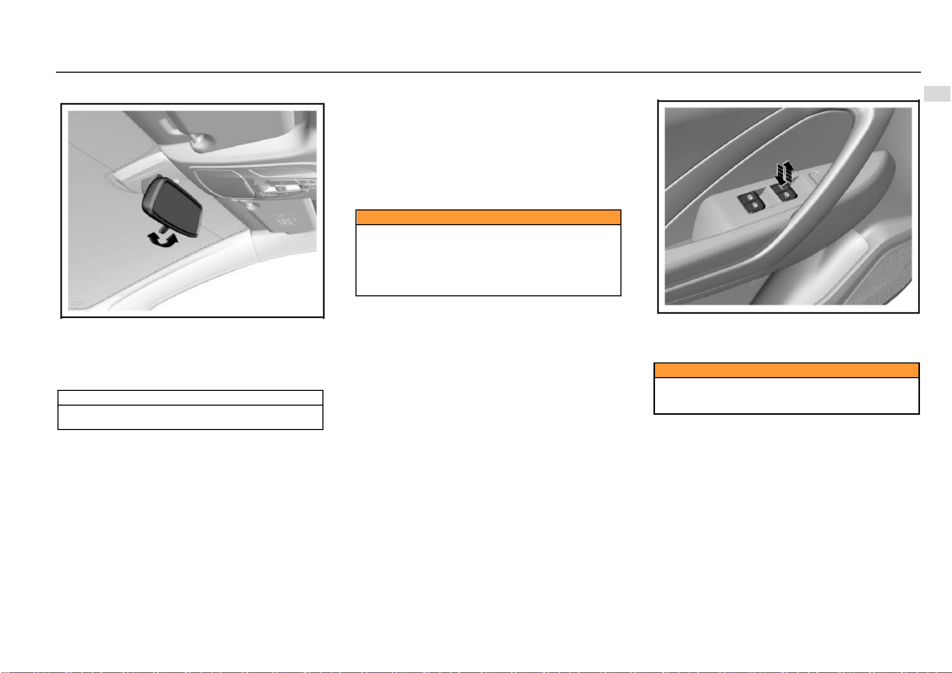
Inside Rearview Mirror
Adjust the rearview mirror to an appropriate angle manually.
The rearview mirror of some models has anti-dazzling
function which can reduce the dazzling effect from vehicles
behind at night. Turn the switch at the rearview mirror
bottom forward to activate the anti-dazzling mode. Please
remember to turn the switch back at day time.
Note
The anti-dazzling mode will reduce the vision clarity
behind the vehicle. Please drive carefully.
Windows
Power Window
When the ignition switch is at ON position, you can control
the power window with the power window switch on the door
armrest panel. You can also use the combination switch on
the driver’s side to control other power windows.
The windows can also be controlled with the power window
switches within 30s after the ignition switch is turned from
ON position to ACC or LOCK position or the key is pulled
out.
Caution
Children may operate the power window and may get
stuck by the window when they operate it.
Do not leave a key or an unattended child in the
vehicle.
Misoperation of the power window may cause
casualties.
Power Window Switch
To raise the window, pull upward the switch.
To lower the window, press down the switch.
When the window reaches the desired position, release the
switch.
Caution
If an occupant stretch his/her body out of the vehicle,
he/she may be hit by objects passing by.
Do not stretch any body part out of the vehicle.
One-button Lowering of Driver’s Side Power Window
The driver’s side power window has the one-button lowering
function. Press the switch to the bottom and release, and
the window will be lowered to the fully-open position
automatically. To stop lowering the window, pull upward the
button and release (short pull is ok).
18 Keys, Doors and Windows
One-button Rising of Driver’s Side Power Window*
The driver’s side power window of some models has the
one-button raising function. To close the window, pull
upward the switch to the top and release, and the window
will be raised automatically to the fully-close position. To
stop raising the window, press down the button and release
(short press is ok).
Anti-pinch Function of Driver’s Side Power Window*
The power window that has the one-button rising function
also has the anti-pinch function to reduce pinching injuries.
The power window will be lowered automatically for a
distance in case of any obstruction in its one-button rising
process.
Remote Lowering of Power Window
Press and hold the unlock button on the remote control key
for about 2s to lower all window glass in turn.
Initialization Learning of Driver’s Side Power Window*
The driver’s side window may lose the on-button rising and
lowering functions in some cases, such as battery
connection after disconnection. In case of such outage, the
window initialization learning shall be conducted first. First,
pull upward the driver’s side switch till the window glass is
closed completely, and continue to pull upward the switch
for at least 5s and release it. Now the initialization learning
is completed. If the one-button raising or lowering function
is still unavailable after initialization learning, it is
recommended to drive to the Aftersales Service Center for
check and repair.
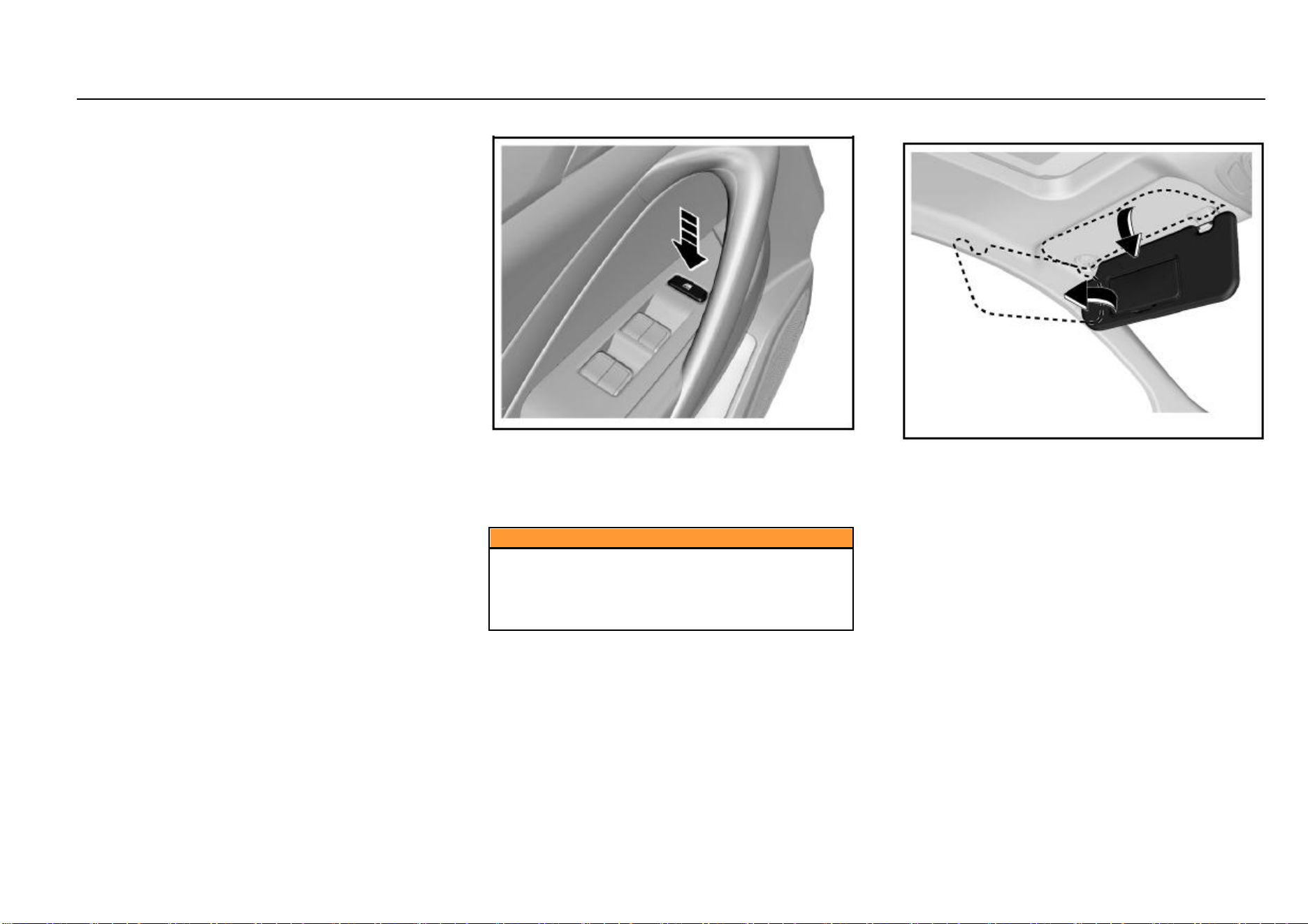
Power Window Lock Button
The power window lock button can lock the front
passenger’s side and rear power window switches. Press
the button, and other power window switches are locked.
The windows can only be operated with the driver’s side
window control panel.
Press the button once again, and the lock can be released.
Caution
Children may operate the power window and may get
stuck by the window when they operate it or may get
out of the vehicle from the window, leading severe
causalities. Please use the power window lock when
there is a child in the vehicle.
Sunshade
Your vehicle is configured with sunshade which can reduce
dazzling effect on the driver and passengers.
The sunshade can move upward, downward and sideward.
Depending on the configuration, the sunshade may be
equipped with a bill fold and vanity mirror.
Keys, Doors and Windows 19
1
Keys, Doors and Windows
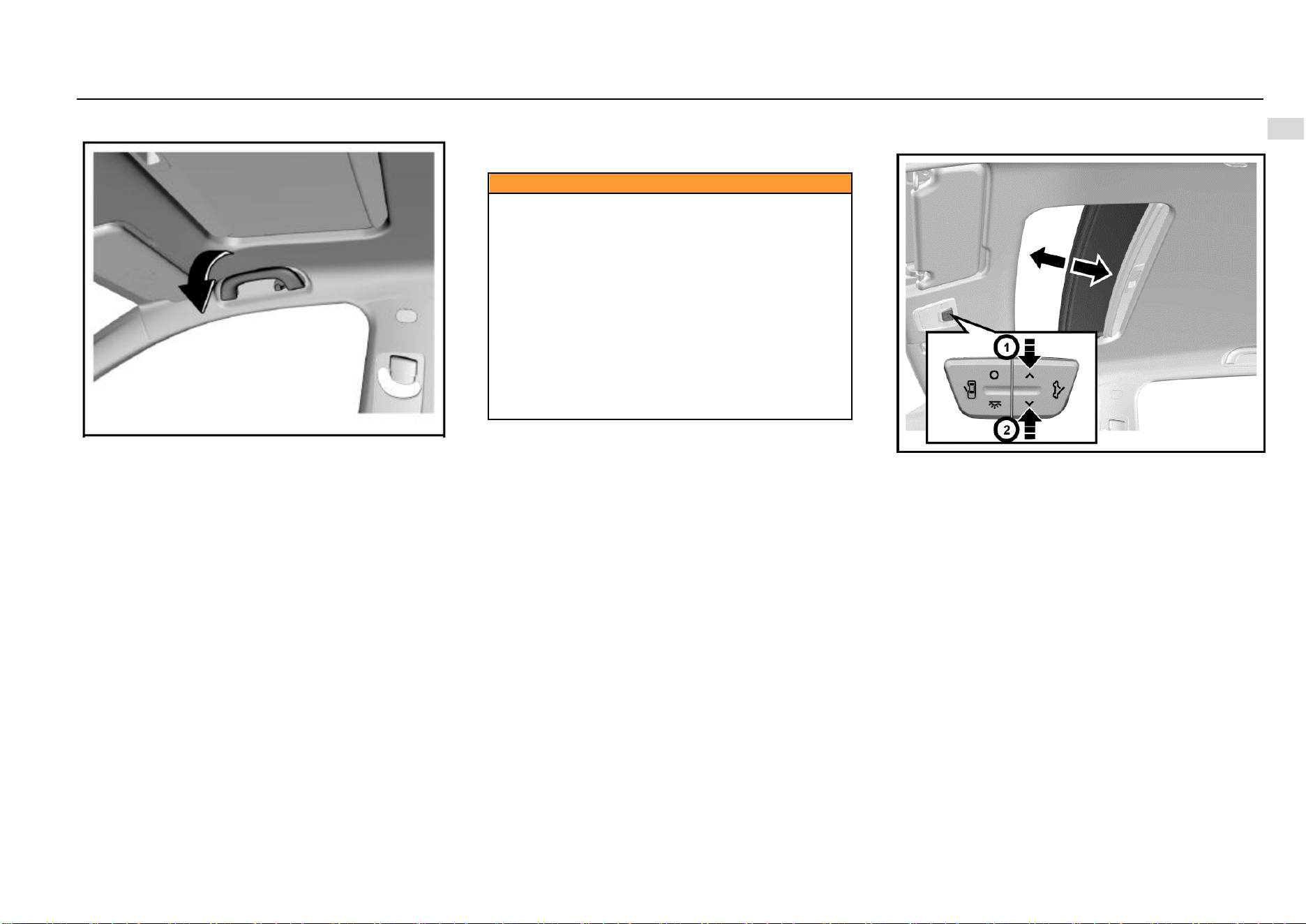
Auxiliary Handrail
Above the front passenger’s side door and rear doors, an
auxiliary handrail is installed. The handrail of some models
is equipped with a clothes hook.
The auxiliary handrail is convenient for passengers to get in
and out of the vehicle. The passengers can also grab the
handrail to help maintain the sitting position when the
vehicle speed is fast.
While using the auxiliary handrail, hold it downward. When
it is released, it will return automatically.
Sunroof*
When the ignition switch is at ON position, the power
sunroof can be operated.
Caution
Always observe the following notes:
• Do not stretch out the body or any object out of the
sunroof.
• Please ensure that there is no object in and out of the
sunroof before the sunroof is opened or closed.
• Do not place a heavy object on or around the sunroof.
• Make sure that there is no rubbish on the outer side
of the sunroof.
• When the vehicle is left unattended, the sunroof must
be closed.
All occupants must buckle seat belts in all cases no
matter whether the sunroof is opened or closed.
If the notes above are not observed, severe injuries or
vehicle damage will be caused.
Power Sunroof*
Sunroof Sliding
To slide open the sunroof, press the rear end of the
switch once quickly and release (operate within 0.3s).
After the sunroof reaches the desired position, press
the front end or rear end of the switch again. Or, press
and hold the rear end, and release the switch after the
sunroof reaches the desired position.
To slide close the sunroof, press and hold the front
end of the switch, and release the switch when the
sunroof reaches the desired position but is not
completely closed. To completely close the sunroof,
press and hold the front end of the switch, and release
the switch when the sunroof stops moving, or press
the front end of the switch once quickly and then
release (operate within 0.3s).
20 Keys, Doors and Windows
Sunroof Tilting
To tilt open the sunroof, press the front end of the
switch when the sunroof is completely closed, and
release the switch when the sunroof reaches the
desired position. To completely tilt the sunroof, press
and hold the front end of the switch, and release the
switch when the sunroof stops moving, or press the
front end of the switch once quickly (operate within
0.3s).
To completely close the tilted sunroof, press and hold
the rear end of the switch, and release the switch
when the sunroof reaches the desired position but is
not completely closed. To completely close the
sunroof, release the switch when the sunroof stops
moving, or press the rear end of the switch once
quickly and then release (operate within 0.3s).
One-button Opening or Closing of Sunroof
While operating the sunroof switch, you can press the front
or rear end of the switch once quickly (operate within 0.3s),
and the sunroof will be closed or opened automatically.
Sunroof Anti-pinch Function
The sunroof will retract to prevent pinching persons when it
contacts a certain rigid obstacle (such as the arm and head)
in its one-button closing process.
Sunroof Initialization Learning
The sunroof may lose its one-button opening or closing
function in some cases, such as replacement of sunroof
glass or motor. In case of such outage, the sunroof
initialization learning shall be conducted first. When the
sunroof is completely closed, press and hold the front end
of the switch; release the switch temporarily and then
continue to press and hold the switch for at least 5s when
the sunroof glass tilts completely; finally, release the switch.
At this time, the sunroof glass will shake slightly, indicating
that the initialization learning is completed. If the one-button
opening of closing function is still unavailable after
initialization learning, it is recommended to drive to the
Aftersales Service Center for check and repair.
Sun Visor
The sunroof visor can only be opened and closed manually.
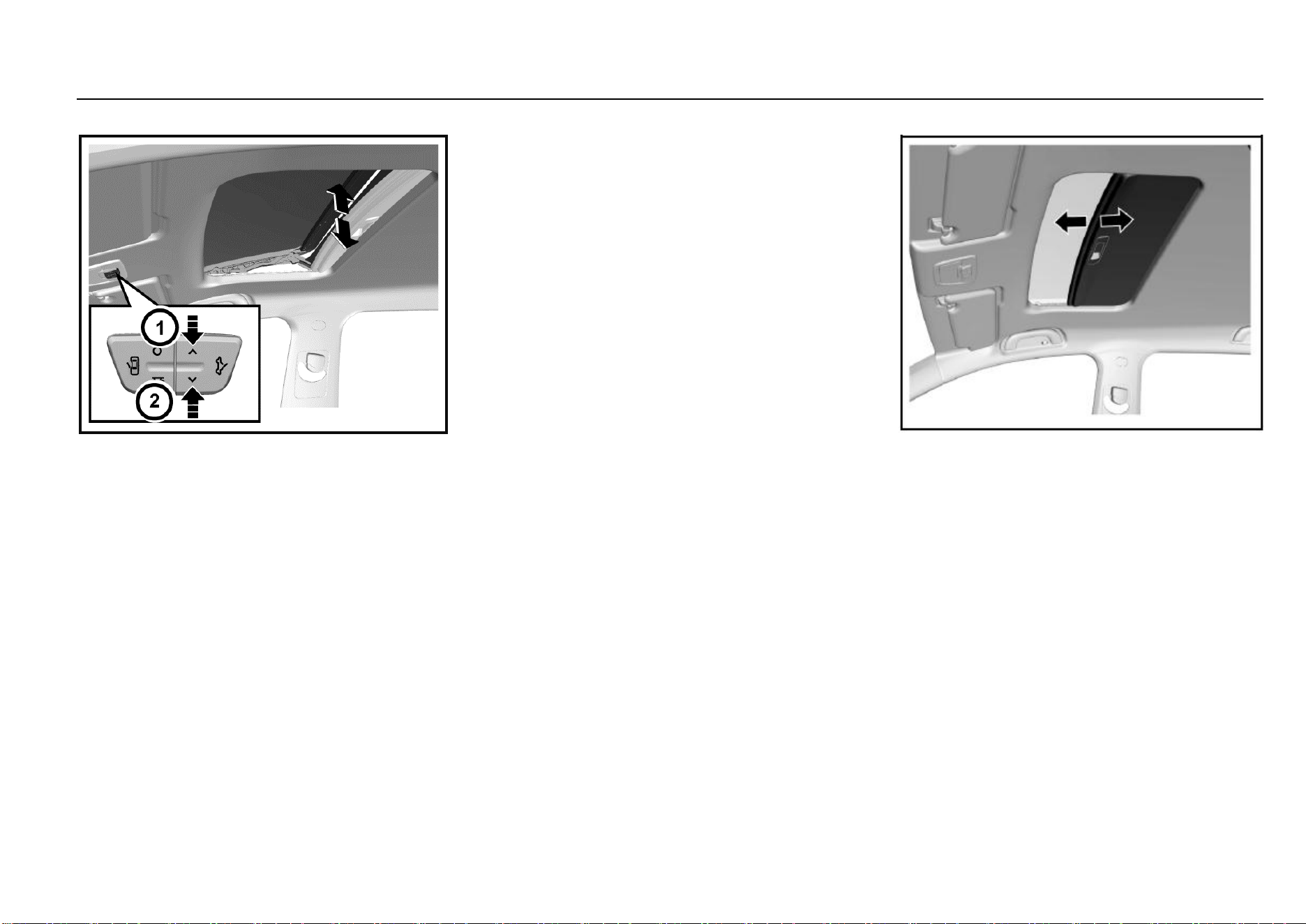
Panoramic Sunroof*
The panoramic sunroof is composed of two parts—the front
part is tiltable and slidable and the rear part is fixed.
Keys, Doors and Windows 21
1
Keys, Doors and Windows
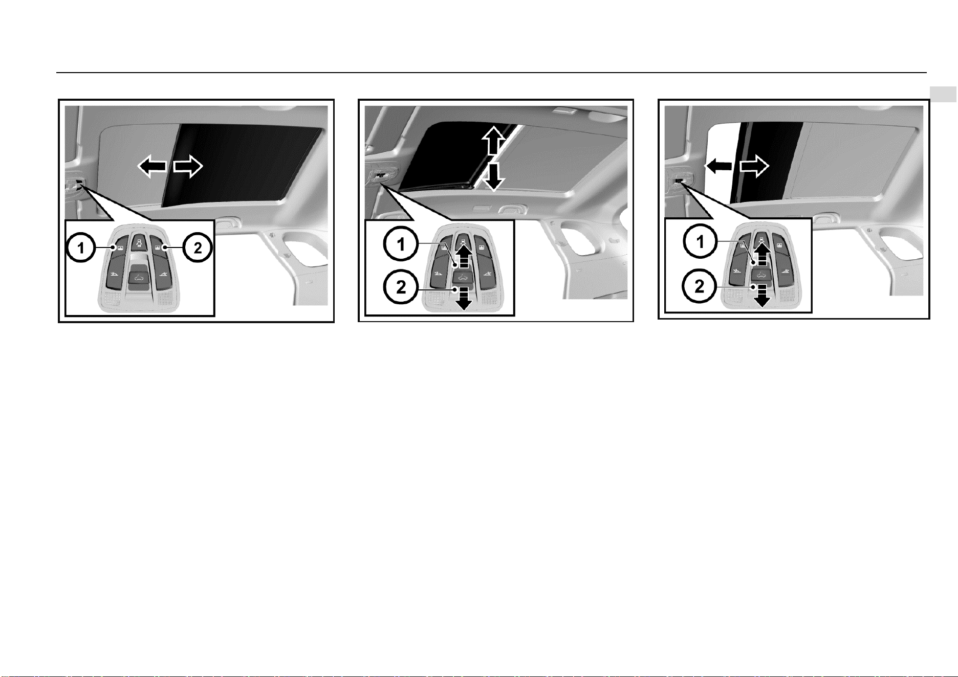
Sun Blind
Press the open or close button of the sun blind to slide open
or close the sun blind. When it reaches the desired position,
release the button.
Short press the button, and the sun blind can be opened or
closed automatically.
Sunroof Tilting
The front part of the sunroof can be tilted.
To tilt open the sunroof, push the sunroof switch backward
when the sunroof is completely closed, and release the
switch when the sunroof reaches the desired position. To
completely tilt open the sunroof, push and hold the switch,
and then release the switch when the sunroof stops moving.
You can also push the sunroof switch (short press)
backward once quickly, and the sunroof will be tilted open
automatically.
To close the titled sunroof, push the sunroof switch forward,
and release the switch when the sunroof reaches the
desired position. To completely close the sunroof, release
the switch when the sunroof stops moving. You can also
push the sunroof switch (short press) forward once quickly,
and the sunroof will be closed automatically.
Sunroof Sliding
The sunroof can be slided open backward after it is
completely tilted open.
To slide open the sunroof, push the sunroof switch
backward, and release the switch when the sunroof reaches
the desired position. You can also push the sunroof switch
backward once quickly (short press), and the sunroof will be
slided open automatically.
To slide close the sunroof, push the sunroof switch forward,
and release the switch when the sunroof reaches the
desired position. To completely close the sunroof, release
the switch when the sunroof stops moving. You can also
push the sunroof switch forward once quickly (short press),
and the sunroof will be slided close automatically.

22 Keys, Doors and Windows
One-button Opening or Closing
Push the switch once quickly (short press) while operating
the sunroof switch, and the sunroof can be closed or opened
automatically.
In the process of opening, push the switch backward once
quickly (short press) to tilt open the sunroof; push again to
slide open the sunroof.
In the process of closing, push the switch forward once
quickly (short press), and the sunroof will be completely
closed automatically.
To stop in the process of automatic opening or closing, push
the switch once.
Anti-pinch Function
The sunroof and the sun blind will retract to reduce pinching
risks when they contact a certain rigid obstacle (such as the
arm and head) in their one-button closing or remote closing
process.
Remote Sunroof Opening and Closing
Press the unlock button/lock button of the remote control for
about 2s, the sun blind and sunroof will completely be
opened/closed automatically.
Sunroof Initialization Learning
The sunroof or the sun blind may lose its one-button
opening or closing function in some cases, such as
replacement of sunroof glass or motor. In such cases, the
sunroof or sun blind initialization learning is necessary.
Method: Move the sunroof or sun blind to the completely
close position; push the sunroof switch forward for about
10s or press the close button of the sun blind for about 10s;
when the operation sound of the sunroof mechanism is
heard, the sunroof or sun blind initialization learning is
completed. If the one-button opening or closing function still
cannot be recovered after initialization learning, please drive
to the Aftersales Service Center for check and repair.
Shutdown Delay Function
Within 30s upon vehicle shutdown, the sunroof and sun
blind can be closed with buttons but cannot be opened.
Linkage Function
The linkage function of the sunroof and sun blind enables
passengers in the vehicle to see the sunroof glass position
when the sunroof is opened and to avoid forgetting to close
the sunroof when the passengers leave the vehicle.
When the sunroof sun blind is completed closed, the sun
blind will move the half-open position along with the sunroof
if the sunroof switch is pushed backward and held. If the
button is released in the long pressing process, the glass
will stop moving immediately, and the sun blind will move to
the half-open position and then stop.
When the sunroof glass is completely opened, if the sun
blind close button is long pressed, the glass will be closed
along with the sun blind. If the button is released in long
pressing process, the glass will stop moving, and the sun
blind will stop moving (not reaching the half-open position)
or return to the half-open position (exceeding the half-open
position).

Seats and Protective Devices 23
2
Seats and Protective Devices
Seats and Protective Devices
Headrest .......................................................................... 24
Position .................................................................. 24
Height Adjustment .................................................. 24
Front Seat ........................................................................ 24
Seat Position and Backrest Normal Condition ....... 24
Seat Position Adjustment ....................................... 25
Seat Backrest Adjustment ...................................... 25
Driver’s Seat Height Adjustment ............................ 26
Middle Seat ..................................................................... 27
Middle Seat (Only for 7-seat Model) ...................... 27
Rear Seat ........................................................................ 28
Rear Seat (5-seat Model) ....................................... 28
Rear Seat (7-seat Model) ....................................... 28
Armrest .................................................................. 29
Seat Belt .......................................................................... 29
Wearing ................................................................. 30
Height Adjustment* ................................................ 31
Unbuckle ................................................................ 31
Middle Row/Rear Row Seat Belt ............................ 31
Seat Belt Use during Pregnancy ............................ 32
Child Seat ........................................................................ 33
Child Restraint System Type.................................. 33
ISOFIX ................................................................... 34
Air Bag System ................................................................ 35
24 Seats and Protective Devices
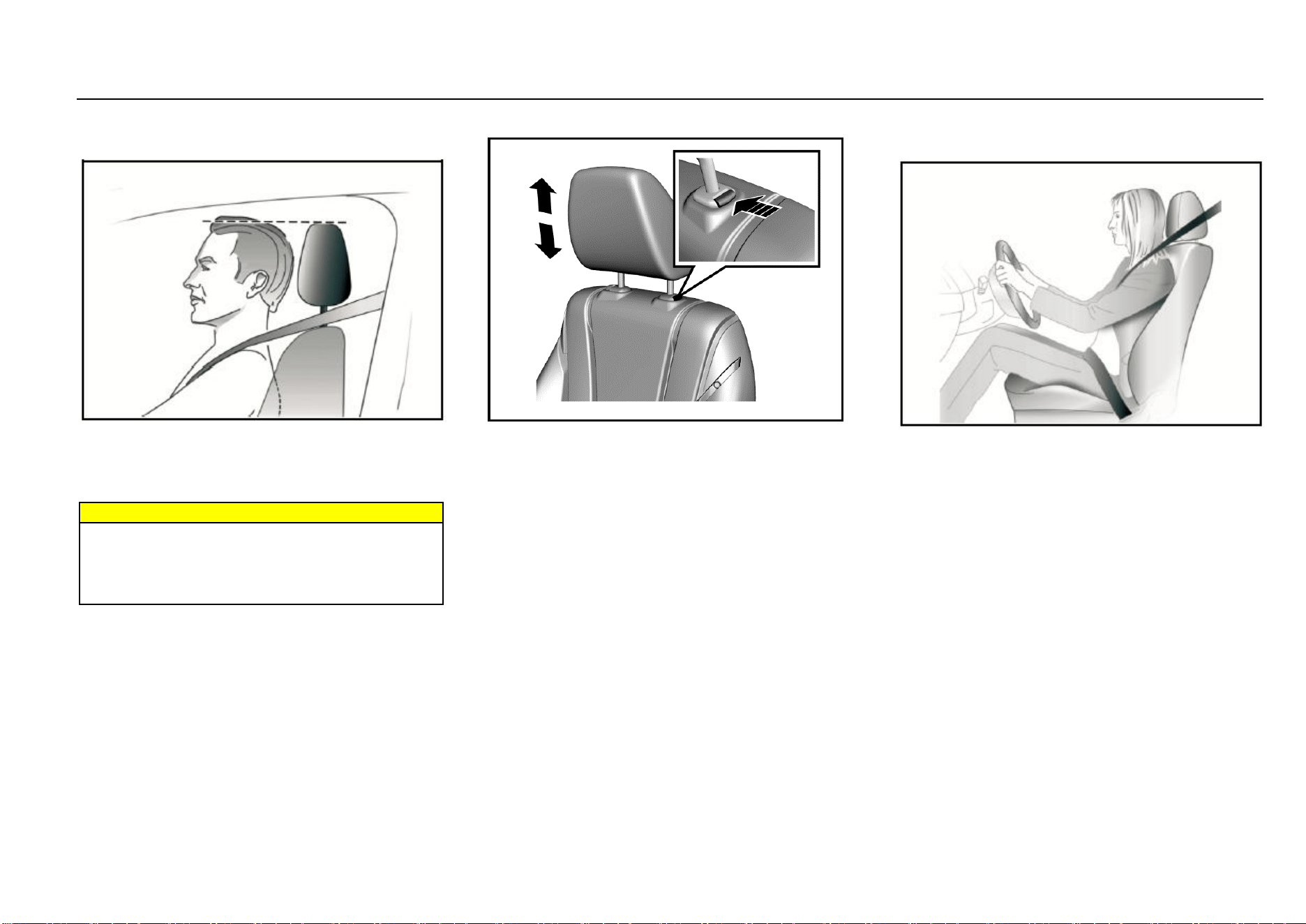
Headrest
Position
The middle position of the headrest should be on the same
horizontal line as the occupant’s eyes. For tall persons, if
the above point cannot be met, the headrest shall be
adjusted to the highest position; for short persons, the
headrest shall be adjusted to the lowest position.
Warnings
Before driving, make sure that the headrest is adjusted
properly.
Removal or improper adjustment of the headrest will
cause severe injuries to the head and neck in collision
accidents.
Height Adjustment
To adjust the headrest upward, pull the headrest upward to
a proper position and fix it. To remove the headrest, press
and hold the release switch.
To adjust the headrest downward, press and hold the
release switch and push the headrest downward to a proper
position; then, release the release switch for fixation.
Pay attention not to press the headrest forcibly to avoid
injuring the finger pressing the release switch.
Front Seat
Seat Position and Backrest Normal Condition
When you sit on the seat, make your hip as close to
the backrest as possible. Adjust the distance between
the seat and the pedal to make your leg slightly bend
when you press the pedal. The passenger’s seat shall
slide as backward as possible.
When you sit on the seat, make your shoulders lean
on the backrest as backward as possible. Set the
backrest inclination angle to make your arm
conveniently to reach the steering wheel while slightly
bending the arm. Keep the shoulders leaning against
the backrest while turning the steering wheel. The
backrest shall not incline excessively backward. We
suggest that the inclination angle of all backrests shall
not be more than 25 degree.
The seat height shall be so set that the occupant can
see all directions and the positions of all display
instruments. The head must be at least one hand
away from the roof lining.
Seats and Protective Devices 25
2
Seats and Protective Devices
The thighs are right on the seat without constriction.
Warnings
Correctly adjust the seat before driving the vehicle.
Never adjust the seat when the vehicle is running
because the seat may not move as controlled.
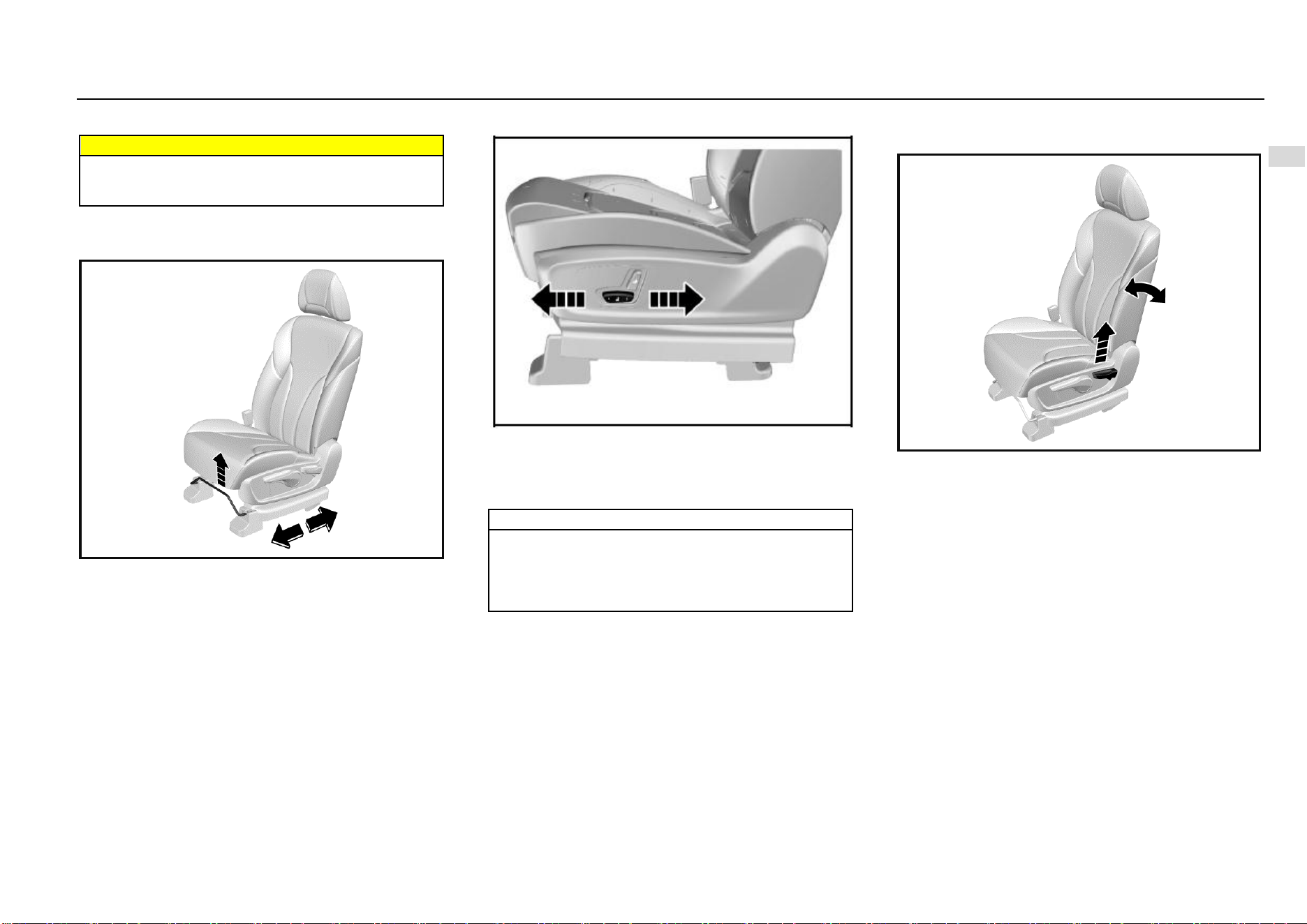
Seat Position Adjustment
Manual Adjustment Type*
Pull upward the adjustment lever on the front lower part of
the seat to adjust the seat forward or backward, and release
the lever after the seat is adjusted to a proper position.
Try to slide the seat forward and backward to ensure that
the seat is locked at a proper position.
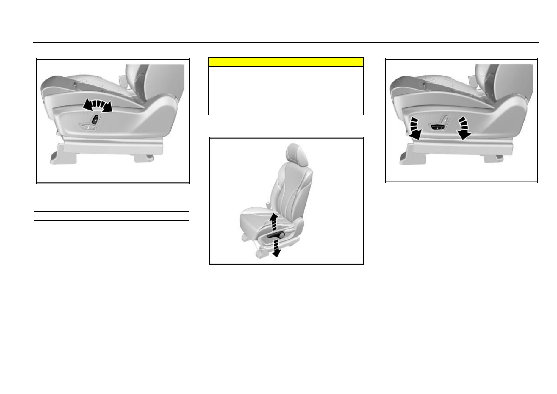
Electric Adjustment Type*
As shown in the figure, the electric adjustment switch is on
the outer side of the seat. Push the switch forward or
backward, and the seat will move forward or backward
accordingly. Release the switch when it reaches a proper
position.
Note
If the seat does not move when the switch is pushed,
the seat may be already at the front or rear limit
position, or the vehicle battery is out of power. Please
check for confirmation. Never turn the switch forcibly
to avoid damaging it.
Seat Backrest Adjustment
Manual Adjustment Type*
Pull up the handle near the seat cushion; adjust the backrest
inclination angle to a proper position; then, release the
handle. Please do not lean on the seat backrest while
adjusting.
After adjusting the seat backrest, try to shake the backrest
to ensure that the backrest is locked.
26 Seats and Protective Devices
Electric Adjustment Type*
As shown in the figure, turn the adjustment switch forward
and backward, and the backrest will be folded forward or
unfolded backward. Release the switch when it is adjusted
to a proper position.
Note
If the backrest does not move when the switch is
turned, the backrest may be already at its limit
position, or the vehicle battery is out of power. Please
check for confirmation. Never turn the switch forcibly
to avoid damaging it.
Warnings
The backrest plays an important protection role when
the vehicle is running. Unlocked backrest may cause
severe personal injuries in case of sudden braking or
a collision.
Any time after adjusting the seat backrest, shake the
backrest to check whether it is locked even though no
passenger occupies the seat.
Driver’s Seat Height Adjustment
Manual Adjustment Type*
Turn the handle on the outer side of the seat upward and
downward until the seat is adjusted to the desired height.
While adjusting the seat height, the seat must be loaded.
Therefore, please sit on the seat before adjustment;
otherwise the adjustment device may be damaged.
Electric Adjustment Type*
As shown in the figure, rotate the height adjustment switch
on the outer side of the seat cushion, and then release the
switch after the seat is adjusted to proper height.
The electrically-adjustable front passenger’s seat cannot be
adjusted upward or downward.
Seats and Protective Devices 27
2
Seats and Protective Devices
Middle Seat
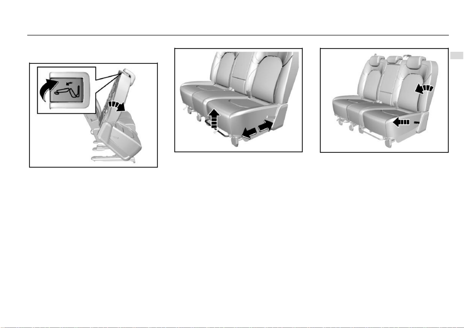
Middle Seat (Only for 7-seat Model)
Overturning Right Seat of Middle Row
For 7-seat models, if a person wants to sit on the rear seat,
please get in the vehicle from the right rear door. Overturn
the right seat of middle row forward first to make room for
getting to the rear seat.
The method of overturning the right seat of middle row:
As shown in the figure, pull up the release handle near the
seat headrest, and overturn and move the seat forward. To
recover, push the seat backward to fix it. Try to shake the
seat to check whether it is fixed.
The left seat of middle row cannot be overturned. Therefore,
if a person wants to sit on the rear row, please do not get in
the vehicle from the left rear door but the right rear door.
Seat Position Adjustment
To adjust the seat forward or backward, pull upward the
adjustment lever on the front lower part of the seat to adjust
the seat forward or backward, and release the lever after the
seat is adjusted to a proper position.
Try to shake the seat to check whether it is fixed.
Seat Backrest Adjustment and Folding
The seat backrest inclination angle is adjustable within a
certain range.
First hold the backrest with hands because the backrest will
be folded quickly and may cause impact or injuries after the
backrest release belt is pulled up. Then, pull the backrest
release drawstring on the seat side backward, and release
the drawstring after a proper angle is obtained.
To fold the seat backrest, pull up the drawstring and fold the
backrest forward. Overturning the seat cushion first and
then folding the backrest can fold flat the backrest to the
greatest extent.
To recover, pull up the drawstring and unfold the backrest
to a proper angle. Finally, try to shake the backrest to check
whether it is fixed.
28 Seats and Protective Devices
Note
Hold the backrest first and do not make the head or
other body parts within the backrest folding range
before pulling the backrest drawstring and folding the
backrest. Otherwise, the backrest will be folded
quickly and may cause impact or injuries.
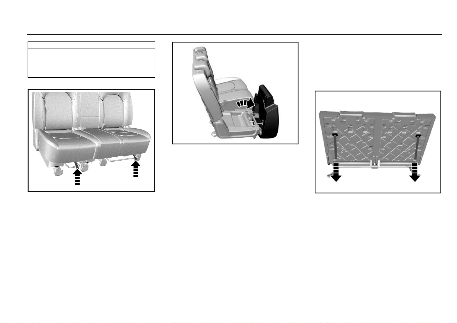
Seat Cushion Overturn
At the front lower position of the seat cushion, there are two
cushion unlock drawstrings; the seat cushion can be
unlocked by pulling the corresponding drawstrings.
As shown in the figure, after the cushion is unlocked, pull
out the cushion forward and lift up the rear part of the
cushion to overturn it. The two cushions can all be
overturned.
To recover, install the cushion back in opposite order, and
press down the cushion with force. Try to shake the seat
cushion to make sure that it is locked.
Rear Seat
Rear Seat (5-seat Model)
Refer to the adjustment method for the middle seat of 7-seat
models for that of the rear seat of 5-seat models. The
difference is that the rear seat cannot be adjusted forward
or backward.
Rear Seat (7-seat Model)
Foldable Seat Backrest
The rear seat backrest is foldable. Pull the drawstring
behind the backrest to unlock the backrest, and then fold the
backrest forward.
To recover, pull the drawstring to unfold the backrest.
Try to shake the seat backrest to check whether it is fixed.
Seats and Protective Devices 29
2
Seats and Protective Devices
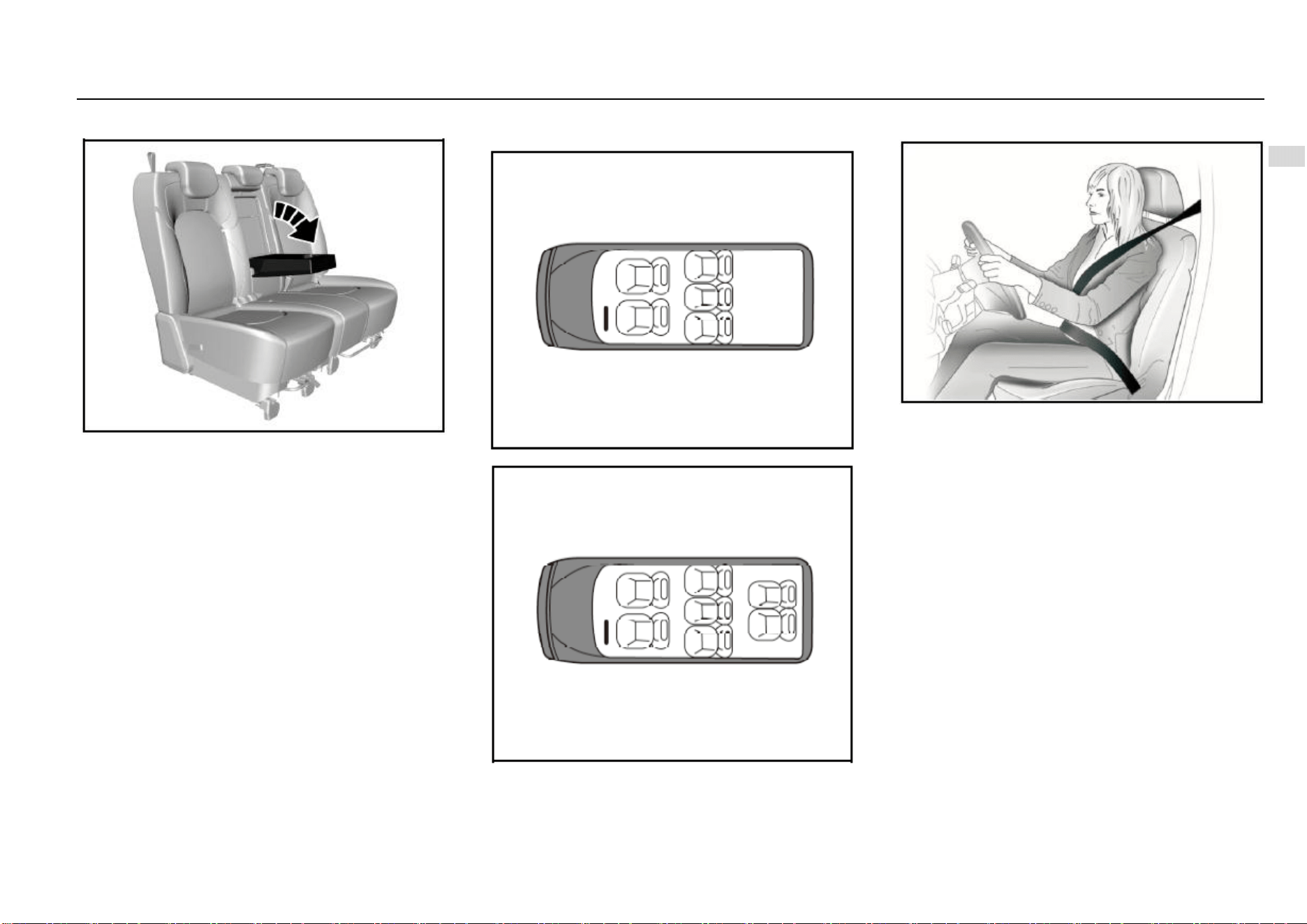
Armrest
As shown in the figure, the second row seat is configured
with an armrest. Deploy the armrest for use. There is a cup
holder on the armrest. After use, please put back the
armrest.
Seat Position and Backrest Angle for Measurement of
Seat Cushion Thickness
For measurement of the seat cushion thickness, the seat
can be in any position.
The seat backrest shall incline backward for a certain angle
from the vertical position. The angle is 23°, 25° and 20°
respectively for the 1st, 2nd and 3rd row.
Seat Layout Diagram
5-seat
7-seat
Seat Belt
The seat belt is designed only for one passenger each time.
It is not applicable to a passenger under 12 years old or
under 150 cm high. Check all parts of the seat belt system
for damage and abnormal function regularly. Please replace
the damaged parts and components. It is strongly
recommended to have the seat belt or deployed seat belt
tensioner at the Aftersales Service Center replaced after an
accident.
Seat Belt Force Limiter*
It is configured on the seat belts for the driver’s seat and the
left seat of second row. For some models, the front
passenger’s seat belt is also configured with a force limiter.
The force limiter can reduce the stress applied on the body
through the seat belt damping release in case of a collision
accident.
30 Seats and Protective Devices
Seat Belt Pretensioner*
Depending on different models, it is configured on the seat
belt for the driver’s seat, front passenger’s seat of the left
seat of the second row. In case of a severe head-on or rear-
end collision, the front part of the seat belt will be tensioned.
The deployed seat belt pretensioner must be replaced by
the Aftersales Service Center. The seat belt pretensioner
can only be deployed once.
Note
Make sure that the seat belt is not damaged or
clamped by a sharp object. Prevent dust from getting
in the seat belt recoiler.
Warnings
Improper operation (for example removal or
installation of seat belt or seat belt anchor buckle) will
trigger the seat belt tensioner, leading to injury risks.
Warnings
Buckle the seat belt each time before driving the
vehicle. In case of an accident, a passenger who does
not buckle the seat belt may be at risk.
Note
It is not allowed to add any accessory or other object
that may interference with the operation of the seat
belt. Do not change any seat belt component.
Warnings
The seat belt shall not be buckled against a hard or
fragile object in your pocket. Otherwise, the hard
object will hurt you and the fragile object may be
damaged in case of emergencies.
Note
Pay attention to prevent foreign matters from getting
in the seat belt buckle (such as sunflower seed shell
and button); otherwise the seat belt buckle will fail.
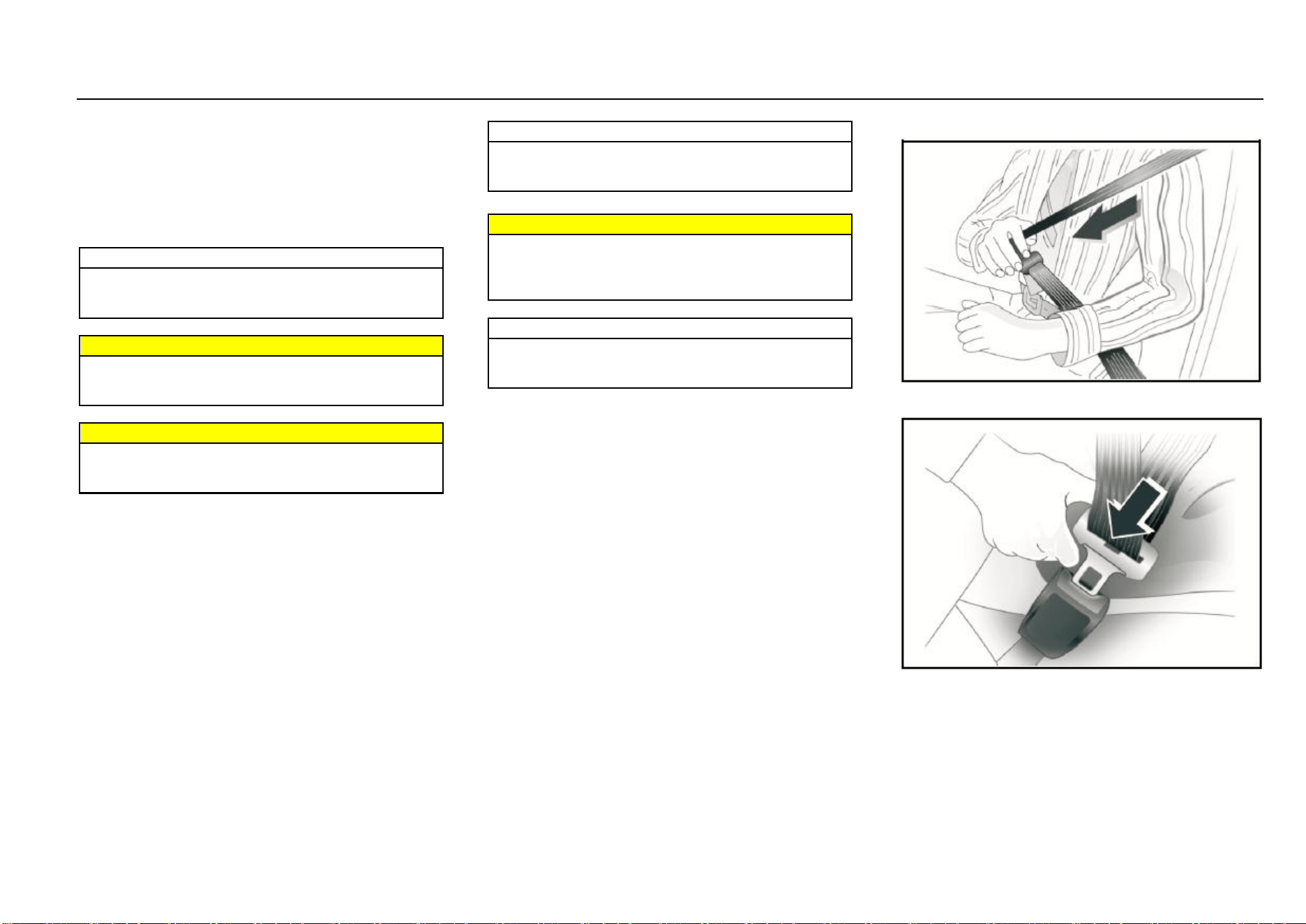
Wearing
1. Pull out the seat belt from the recoiler, and fasten it
across the body without twisting.
2. Put the latch plate in the buckle for fixing. Pull the
shoulder belt forcibly to adjust the tightness degree of
hip belt.
Loose or heavy clothing will hamper close wearing the seat
belt. Do not place any object (such as hand bag and mobile
phone) between the seat belt and your body.
Seats and Protective Devices 31
2
Seats and Protective Devices
Height Adjustment*
Depending on different models, the front row seat belt of
some models can be adjusted in height. Press the height
adjuster of the seat belt upper fixing point and move it
upward or downward. Release the adjuster after
adjustment.
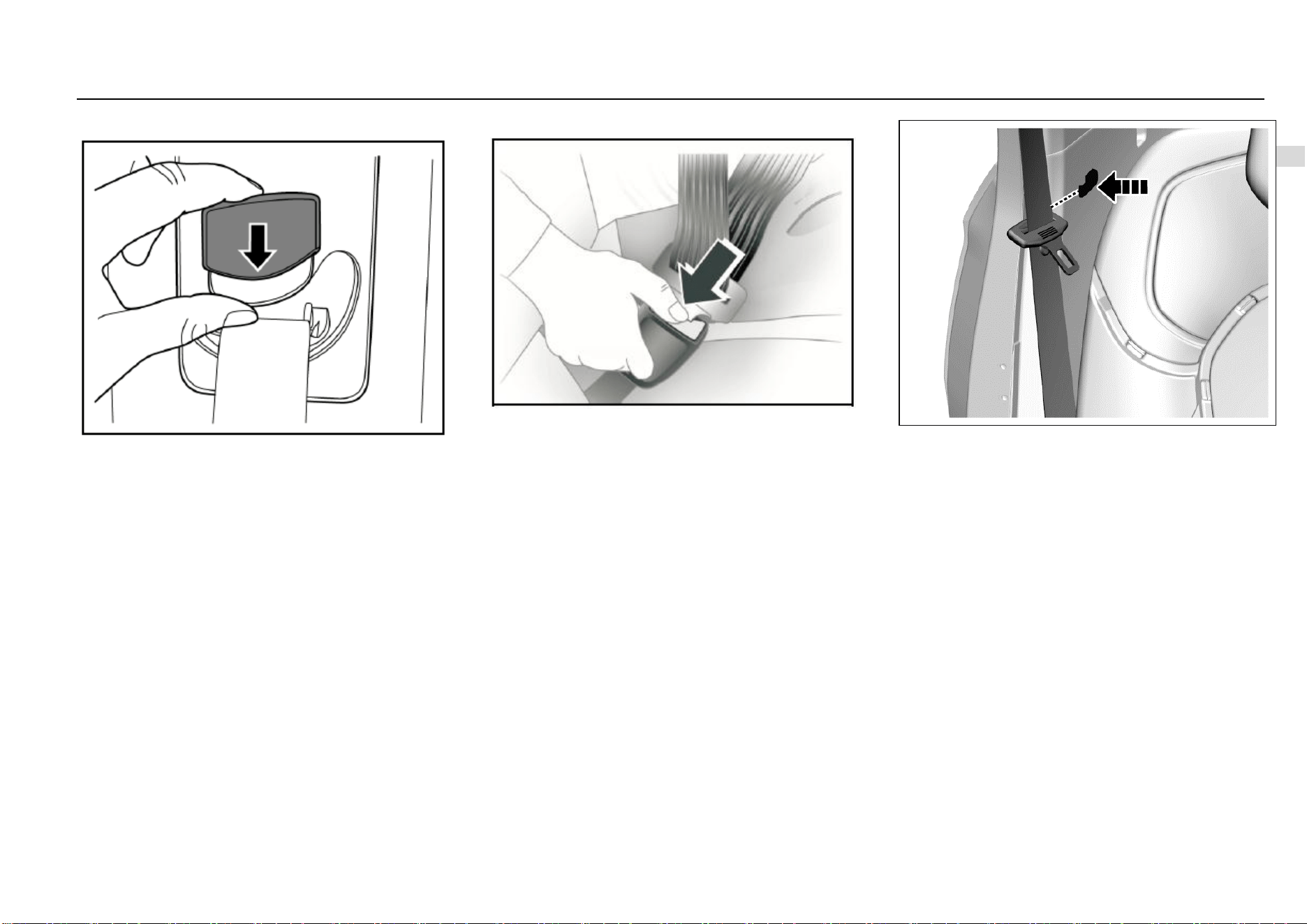
Unbuckle
To unbuckle the seat belt, please press the red button on
the buckle.
Middle Row/Rear Row Seat Belt
Left and Right Seat Belt
For buckling and unbuckling of the left and right seat belts
of the middle row, please refer to that of the front seat belt.
As shown in the figure, there is a clip on the trim panel near
the second row seat backrest. Please hang the seat belt to
the clip for fixing each time after use.
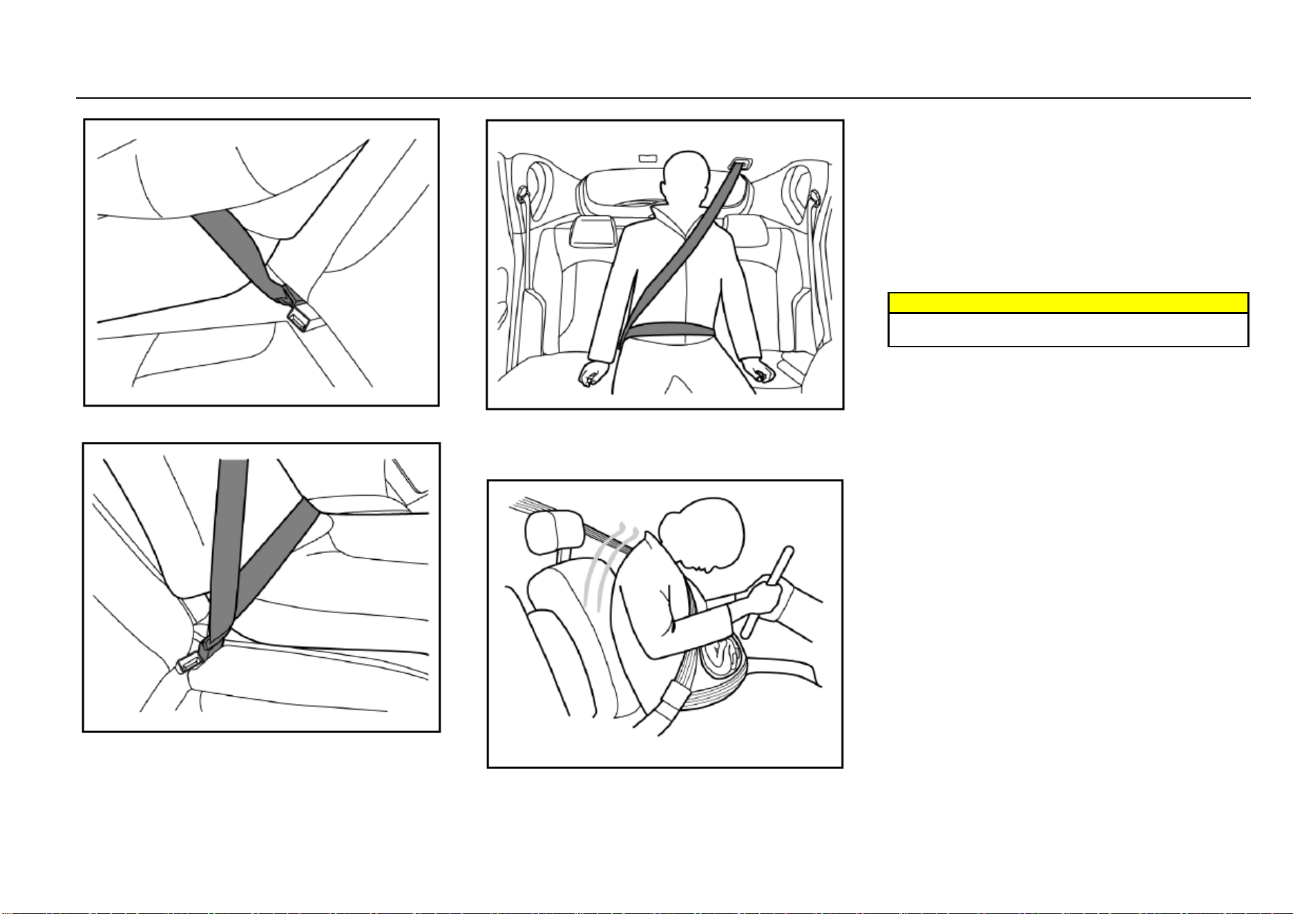
Middle Seat Belt of Second Row
Wearing:
1. Pull out the seat belt from the recoiler on the roof (5-
seat models) or backrest (7-seat models) first and sit
well.
32 Seats and Protective Devices
2. Plug the latch plate at the seat belt end into the small
buckle on the left side of the seat.
3. Plug the other latch plate (movable) into the buckle on
the right side of the seat.
4. Check as shown in the figure above, and make sure
that the seat belt goes across the occupant’s body
without twisting.
Seat Belt Use during Pregnancy
The seat belt provides protection for everybody, including a
pregnant woman. Like all passengers, if pregnant women
do not wear the seat belt, severe personal injuries are more
likely to be caused to them. The pregnant woman shall wear
the hip/shoulder seat belt during the whole pregnancy, and
the hip belt shall be fastened as low as possible. The best
way to protect a fetus is to provide safety protection to its
mother. If the seat belt is fastened correctly, the fetus is not
vulnerable to injury in case of a collision. For a pregnant
woman or any person, correct wearing is the key to exert
the best protection effect of the seat belt.
Warnings
The hip belt shall be placed as low as possible to go
across the pelvis, so as avoid force on the belly.
Seats and Protective Devices 33
2
Seats and Protective Devices
Child Seat
The vehicle is not equipped with a child seat. If you want to
add one, a child seat that is applicable to ISOFIX “general”
type can be selected. The child seat can only be placed on
the second row seat. The front seat is not equipped with the
anchor system bracket. The statistical data of accidents
show that placing the child seat on the second row seat can
largely improve the child safety.
Caution
For a little child, a child seat shall always be used.
Never hold a child with arms while riding in the
vehicle. Never allow a child to stand or kneel on a seat
or in the luggage compartment when the vehicle is
running.
Caution
An unfixed child seat may be thrown out of the vehicle
in case of a collision or emergency stop. The child seat
must be correctly and securely fixed even it is not
used.
Caution
If the child seat is put in a closed compartment in hot
weather, the child seat temperature will be very high.
Make sure that the child seat temperature is not very
high before putting a child in the seat. If the child is
too small and the seat belt cannot provide the best
protection for it, please make sure that a proper child
seat is used to provide safety protection.
Caution
The size and configuration range of the child seat is
very wide. Not all child seats are applicable to your
vehicle due to the effects of the vehicle trim as well as
the seat shape and size. You have responsibility to
ensure that the child seat installed matches with your
vehicle and that the child seat can be connected
correctly to the vehicle with the child seat anchor
system. If the child seat does not match with your
vehicle size and the child body figure or the
connection to your vehicle is incorrect, severe
personal injuries will be caused to the child and other
passengers in the vehicle in case of a collision.
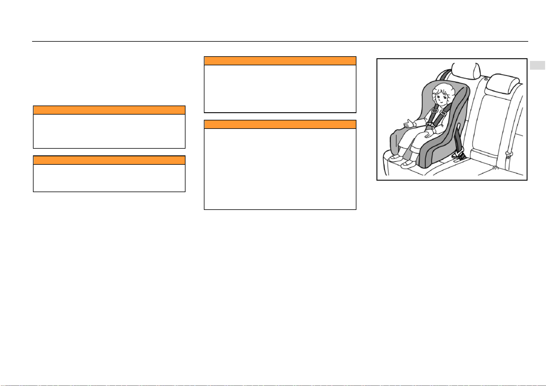
Child Restraint System Type
According to GB27887-2011, the child restraint system can
be classified as the following 5 groups:
Group 0: for child with body weight less than 10 kg.
Group 0+: for child with body weight less than 13 kg.
Group I: for child with body weight more than 9 kg and less
than 13 kg.
Group II: for child with body weight more than 15 kg and less
than 25 kg.
Group III: for child with body weight more than 22 kg and
less than 36 kg.
Please select a suitable child seat according to the child
body weight and body figure.
For infants under one year old, their bones are very fragile,
and a backward-facing child seat shall be used.
34 Seats and Protective Devices
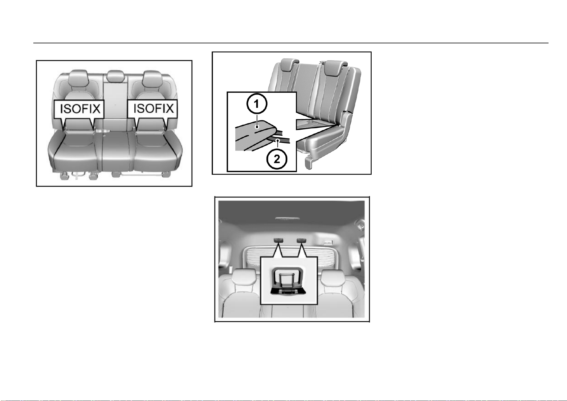
ISOFIX
To fix the child seat:
1. The ISOFIX lower fixing point is on the joint between
the second row set backrest and the seat cushion
back. Its position can be identified through the label
on the lower edge of the backrest. The left and right
seats are equipped with a set of ISOFIX respectively.
2. Clear up the objects on the seat. Note to remove the
seat belt and seat belt buckle to avoid affecting
accurate fixing of the child seat.
3. Put the child seat on the second row seat.
4. Connect the fixing caliper on the child seat to the on-
vehicle fixing device. Operate according to the child
seat instructions.
5. Connect the upper strap of the child seat to the
corresponding fixing point of the vehicle. Refer to the
child seat instructions to get to know when and how
to strain the upper strap. As shown in the figure, the
ISOFIX upper fixing point is on the roof above the rear
seat. Open the outer cover from the upper edge. The
child seat upper fixing point of 7-seat models is
located on backside of the second row seat backrest.
6. Push and pull the child seat in all directions to make
sure it is safely secured.
7. Make sure that the child seat temperature is not very
high before putting a child in the seat.
In case of a serious collision accident, the ISOFIX may be
damaged. It may be necessary to repair and replace some
parts. Please check the ISOFIX after a collision.
Seats and Protective Devices 35
2
Seats and Protective Devices
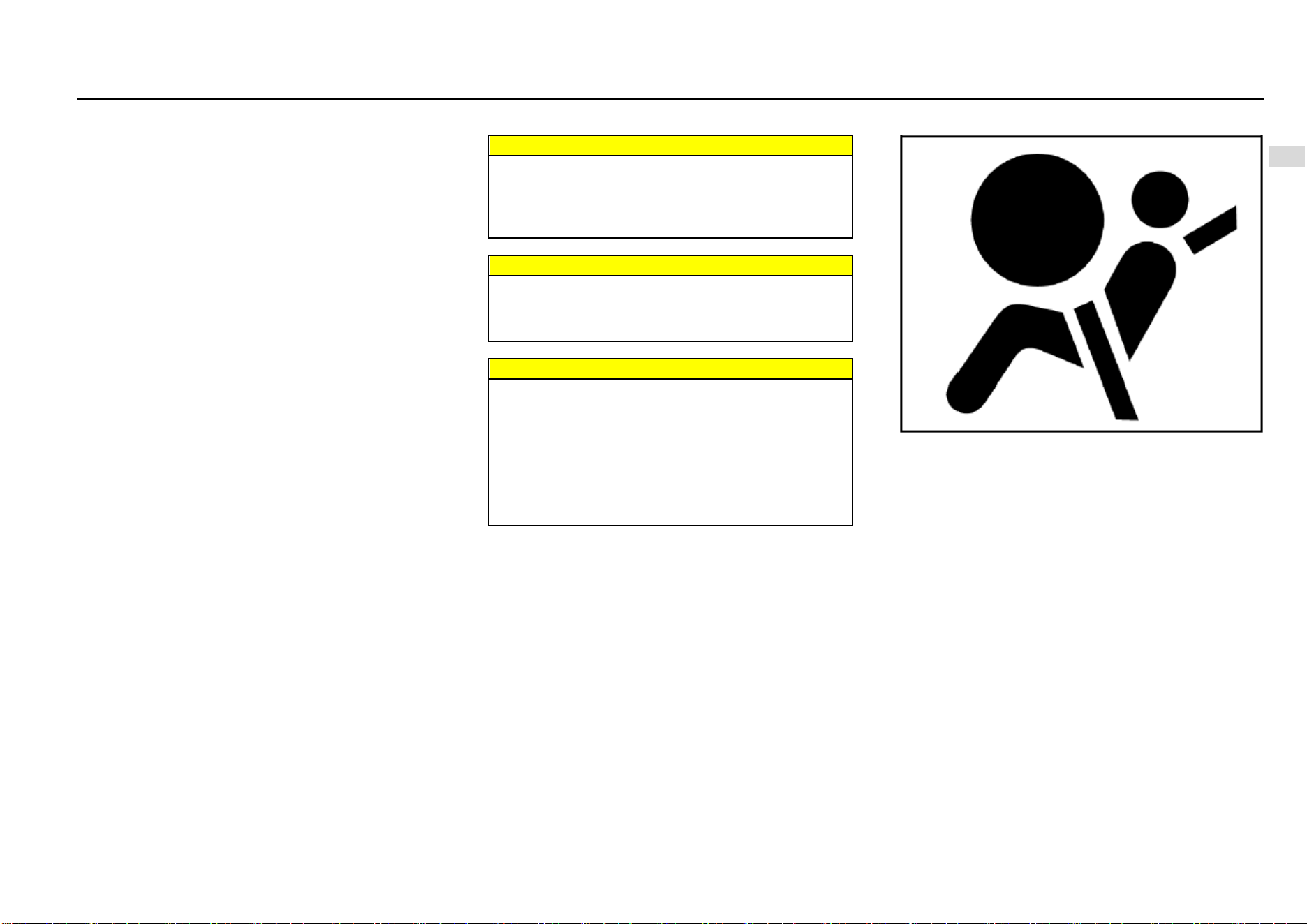
Air Bag System
Depending on the vehicle configuration, the system includes
the following air bags:
Driver frontal air bag.
Front passenger frontal air bag. (If equipped)
Front side air bag. (If equipped)
For all air bags, the letter “AIRBAG” is marked on the trim
panel or the label near to its deployment opening. For frontal
air bags, the letter “AIRBAG” for the driver is located in the
middle of the steering wheel, and that for the front
passenger is located on the instrument panel. For lateral-
impact air bags, the letter “AIRBAG” is located on the
backrest side, near to the door. The letter “AIRBAG” for side
curtain air bags is located on the roof lining trim panel.
The air bag can supplement protection on the basis of
correcting wearing the seat belt. Although nowadays the air
bags are designed to reduce the injury risks caused by the
impact force when the air bag is inflated, all air bags must
be inflated rapidly to exert its effect.
The important notes about the air bag system are as follows:
Warnings
Even if an air bag is equipped, you may also be injured
seriously or lose your life in a collision accident if you
do no use the seat belt. The air bag is designed to be
used along with the seat belt but not to replace the
seat belt.
Warnings
If an occupant sits next to or get too close to the air
bag, he/she may be injured seriously or lose life due
to inflating of the air bag. Therefore, never sit too close
to the air bag.
Warnings
It is forbidden to let a child, infant, pregnant woman
and the sick and weak sit on the front seat equipped
with air bag. Never install a backward-facing child seat
on the front seat for the child may be injured seriously
or lose life when the air bag is inflated. The seat belt
and air bag can protect adults and adolescents but not
children and infants. Children and infants need special
child protection devices (such as child seat) to get
corresponding protection.
Air Bag Indicator
On the instrument panel, there is an air bag indicator which
displays the air bag shape symbol. The system will check
whether the air bag circuit system has a fault and give
corresponding prompt through the indicator. Refer to the
Chapter “Instruments and Controls” for detailed information.
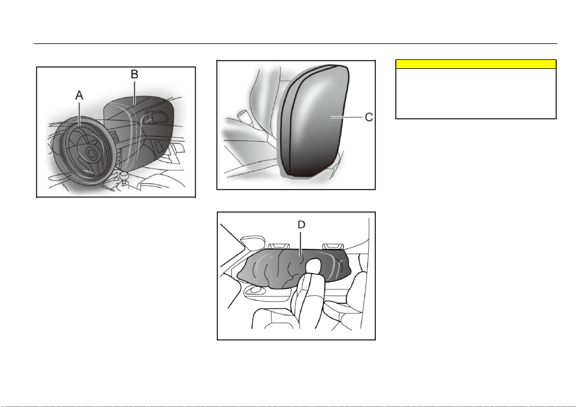
36 Seats and Protective Devices
Air Bag Position
Frontal Air Bag
As shown in the Figure A above, the driver frontal air bag is
located in the middle of the steering wheel.
As shown in the Figure B above, the front passenger frontal
air bag is located in the passenger’s side instrument panel.
Side Air Bag*
As shown in the Figure C, the front seat side air bag is
installed on the backrest side near to the door.
Side Curtain Air Bag*
Warnings
If there is any other object between the occupant and
the air bag, the air bag may not be able to be inflated
normally or the air bag may cause the object to
squeeze the occupant’s body when it is inflated,
leading to severe injuries or even death. Please never
use a seat accessory (such as seat jacket) that may
hinder the inflating of the lateral-impact air bag.
When Shall the Air Bag Be Inflated?
The frontal air bag is designed to be inflated in moderate to
severe head-on collision or almost head-on collision to
reduce severe injury risks of the driver’s and the front
passenger’s head and chest.
Whether the frontal air bag is inflated do not mainly depends
on the vehicle running speed. It depends on the impacted
object, impact direction and vehicle deceleration within unit
time during collision.
The frontal air bag may be inflated in different collision
speed. The air bag inflation depends on the impact direction
(straight or in certain angle) at the moment of collision and
whether the impacted object is fixed or movable, deformable
or not and narrow or wide. Due to different design of each
vehicle, the collision inflation conditions of the frontal air bag
may vary. The frontal air bag will not be inflated in case of
vehicle overturn, rear-end collisions and most lateral-impact
collisions. The frontal air bag may not be inflated in slight
head-on or nearly head-on collisions, lateral or diagonal
collisions, collisions to cylindrical objects (such as telegraph
pole and tree trunk), rear-end collisions under large vehicle
(trucks, etc.) breast board and lateral glancing collisions. As
per the design, the seat lateral-impact air bag and the side
curtain air bag will be inflated according to the impact
position in case of the moderate to severe lateral collisions.

Seats and Protective Devices 37
2
Seats and Protective Devices
The seat lateral-impact air bag will not be inflated in case of
head-on collisions, nearly head-on collisions, vehicle
overturn or rear-end collisions. The seat lateral-impact air
bag \ may not be inflated in slight side collisions and lateral-
frontal or diagonal collisions.
As per the design, the seat lateral-impact air bag and the
side curtain air bag will be inflated on the side to which the
vehicle is collided. The air bag will not be triggered in all
collision accidents. For a particular accident, it shall not
simply judge whether the air bag should be inflated
according to the causalities, vehicle damage or repair and
maintenance expenses. Your vehicle is equipped with a
collision sensing and diagnosis module. If a collision
accident reaches certain strength, the module may record
relevant collision information after the collision. If you have
any doubt on the working situation of your air bag in a
collision accident, please contact the Aftersales Service
Center timely to provide professional analysis and diagnosis
for you.
How Is the Air Bag Inflated?
In the inflation process, the sensing system will send an
electronic signal to trigger the gas generator; the generator
will release gas to inflate the air bag and to make the air bag
pops up from the cover plate. The gas generator, air bag
and relevant members are all components of the air bag
module.
How Does the Air Bag Provide Protection?
The air bag supplements protection provided by the seat
belt by distributing the impact force more evenly to the
occupant’s body. However, some occupants’ bodies do not
move toward the air bags in collisions where an external
object intrudes into the vehicle. The air bag cannot provide
corresponding protection. The air bag shall only be deemed
as a supplementary device of the seat belt.
What Will Your See After the Air Bag is Inflated?
After the air bag is inflated, it will be deflated quickly.
Somebody may not note that the air bag is ever inflated
because the bleeding speed is very fast. For deflated air
bag, some smoke and dust may come out from its air event.
Warnings
When the air bag is inflated, there may be dust spread
in the air. All persons in the vehicle shall get off the
vehicle as soon as possible. If you have a breathing
problem and cannot get off the vehicle, open windows
or doors to get fresh air. If you have a breathing
problem after the air bag is inflated, please see a
doctor as soon as possible.
If the vehicle power supply system can still function normally
after a collision, the vehicle has the functions of unlocking
doors automatically, turning on the hazard warning lamp
and cutting off the fuel system after the air bag is inflated.
The driver can use corresponding function switch to lock
doors, turn off indoors lamps and turn off the hazard warning
lamp.
The deployment of the front passenger air bag may also
cause damage to the windshield.
The air bag can only be inflated once as per its design.
After the air bag is inflated, some parts of the air bag
system need to be replaced. If you do not have these
parts replaced, the air bag system will unable to
provide protection in next collision accident. The air
bag system parts that shall be replaced include the air
bag module, air bag control module, seat belt
pretensioner and other parts.
Work related to the air bag system can only be done
by technicians with corresponding qualification.
Improper repair and maintenance may cause that the
air bag system cannot function normally. Please drive
to the Aftersales Service Center for repair and
maintenance.
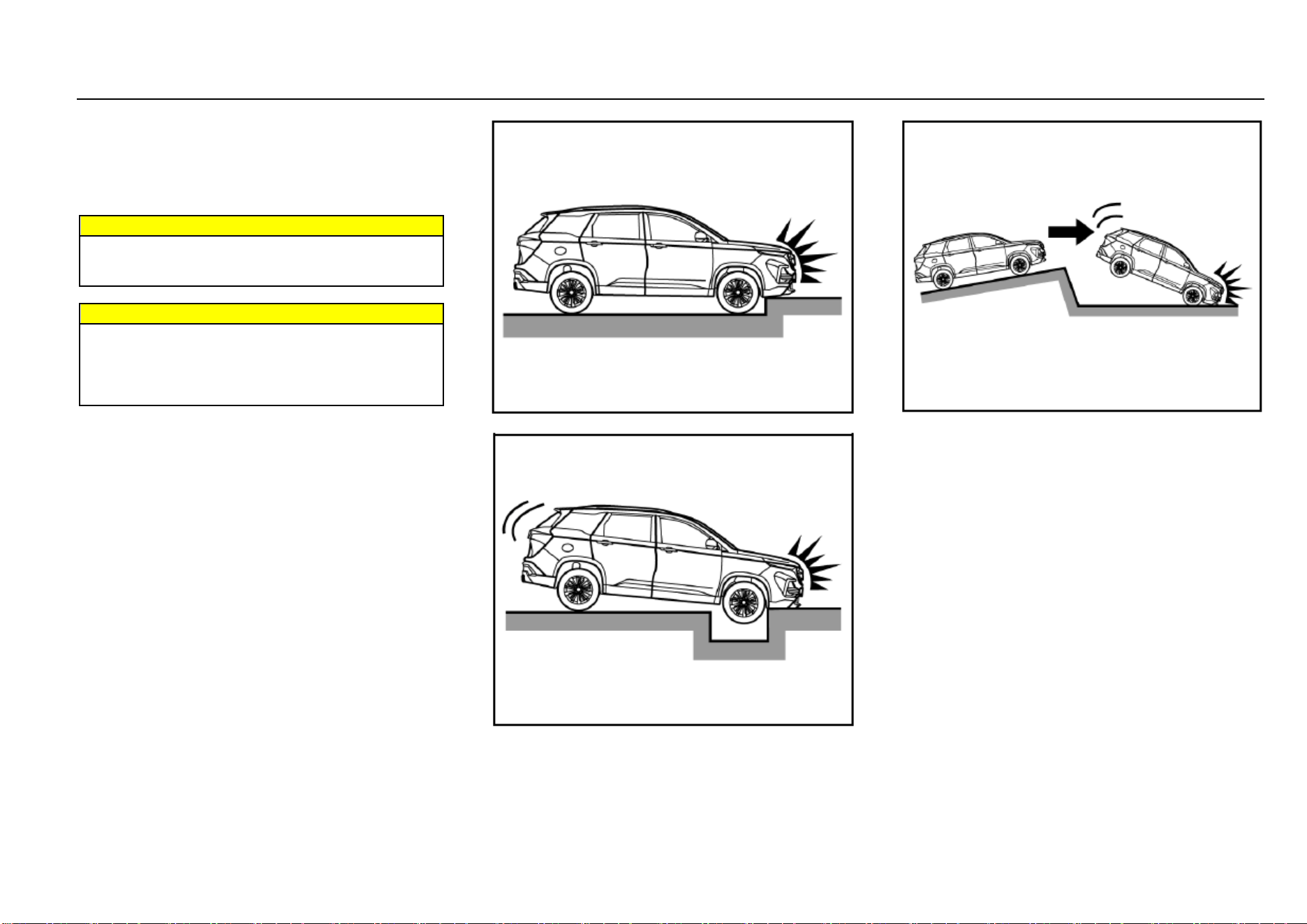
38 Seats and Protective Devices
Air Bag System Repair, Maintenance and Replacement
The air bag system must be maintained by qualified and
professional technicians. Improper maintenance will cause
that the air bag system cannot function normally. Please
drive to the Aftersales Service Center for repair and
maintenance of the air bag system.
Warnings
If the air bag cover is damaged, opened or broken, the
air bag may not function normally. It shall be repaired
as soon as possible.
Warnings
Never stick or cover any object on the air bag cover
surface or refit the air bag cover; never try to repair,
adjust or remove or install any air bag system
component; never try to refit the front bumper of the
vehicle body by yourself.
Other Situations Where the Air Bag May Be Inflated
(Deployed) Except for Collision
If the vehicle bottom is impacted seriously, the air bag may
also be inflated. Refer to the following examples.
Hit a road shoulder, sidewalk edge or hard surface.
Fall into or drive into a deep pit
Wheel hard landing or vehicle fall
The Frontal Air Bag May not Be Inflated in the Following
Collisions
The frontal air bag will usually not be inflated in case of side
collisions, rear-end collisions, turnover or low-speed head-
on collisions. No matter what kind of collision, only when the
vehicle generates sufficient forward deceleration, will the
frontal air bag be inflated.
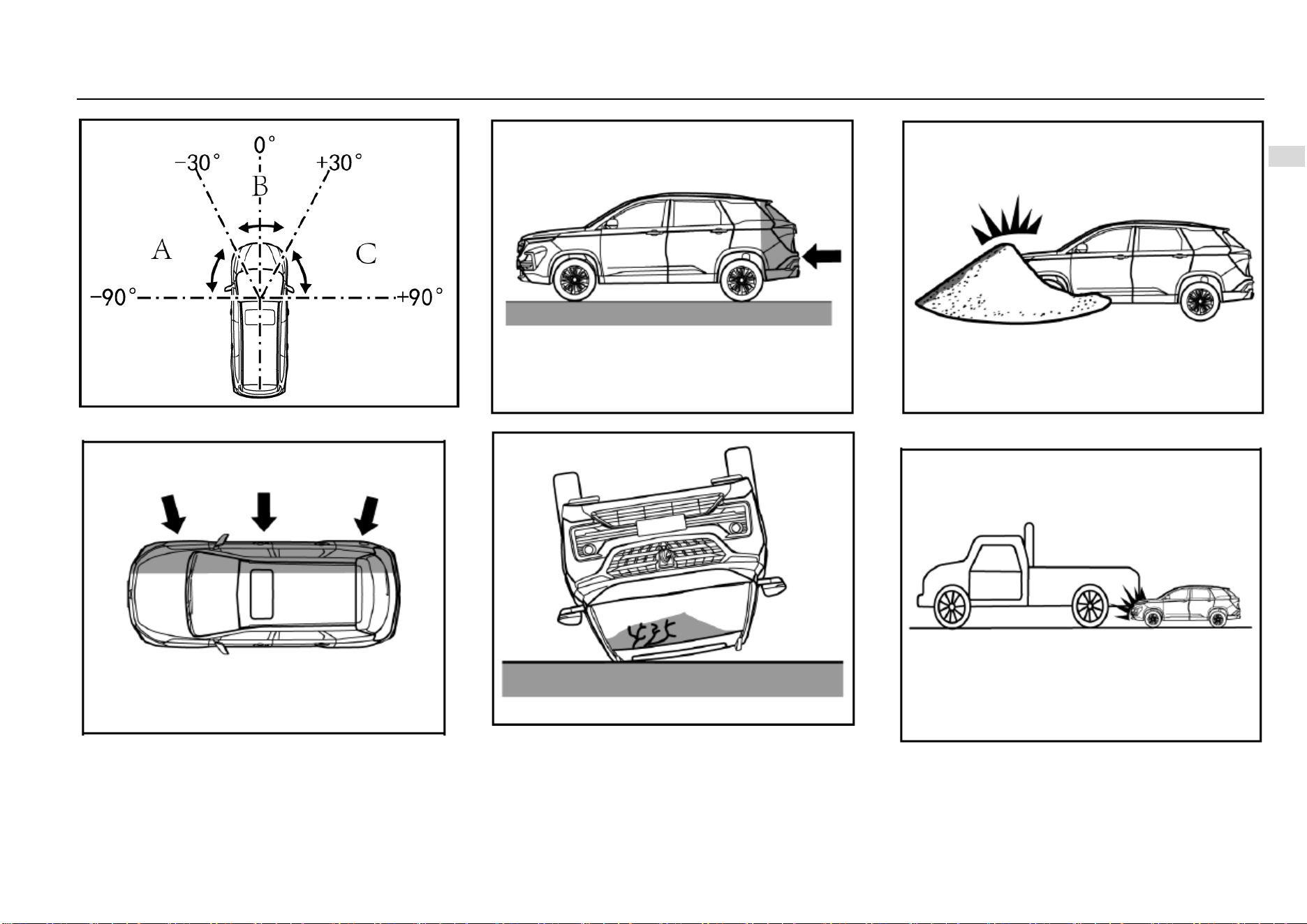
Seats and Protective Devices 39
2
Seats and Protective Devices
Head-on collision angle over 30° from vehicle
longitudinal direction
Side collision
Rear-end collision
Overturn, falling from high place, rolling
Hit deformable objects, such as sandpile, guard bar,
column and tree
Hit into front vehicle bottom, especially truck bottom
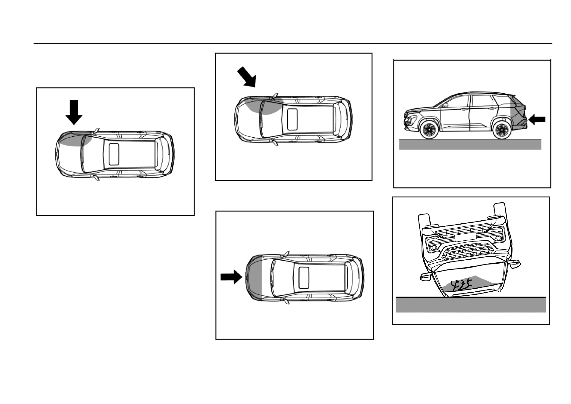
40 Seats and Protective Devices
Side Air Bag/Side Curtain Air Bag (If Equipped) May not
Be Inflated in the Following Collisions
In case of side collisions with certain angle or collisions to
vehicle body side (not passenger compartment), the side air
bag/side curtain air bag system may not be activated.
Vehicle body side (not passenger compartment)
collision
Off-vertical side collision
The side air bag/side curtain air bag will usually not be
inflated in case of head-on collision, rear-end collisions,
overturn or low-speed side collisions.
Head-on collision
Rear-end collision
Overturn, falling from high place, rolling
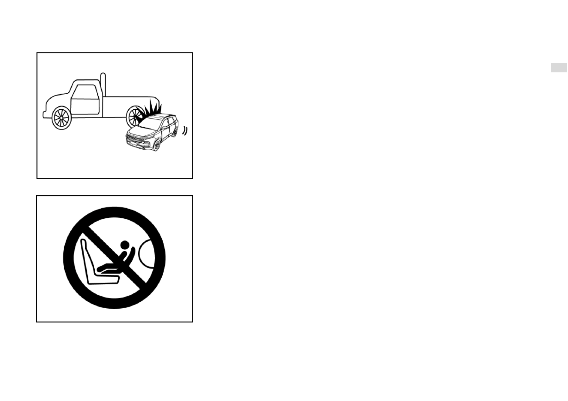
Seats and Protective Devices 41
2
Seats and Protective Devices
Side collision to truck during drifting
Important Note
Do not use a backward-facing child restraint system on a
seat (front seat) protected by a frontal air bag (in activated
state). Otherwise, severe injuries or even death may be
caused to the child when the air bag is deployed.

42 Storage
Storage
Storage Box ..................................................................... 43
Instrument Panel Left Storage Box ........................ 43
Instrument Panel Central Storage Box ................... 43
Armrest Storage Box .............................................. 43
Glasses Box* ......................................................... 43
Console Storage Box* ............................................ 44
Glove Box .............................................................. 44
Map Pocket ..................................................................... 44
Cup Holder ...................................................................... 45
Door Storage Groove and Armrest .................................. 45
Rear Side Wall Storage Groove and Armrest .................. 45
Backrest Hook ................................................................. 46
Card Slot ......................................................................... 46
Ashtray* ........................................................................... 46
Luggage Compartment Cargo Cover* ............................. 47
Roof Rack ........................................................................ 48
Load Information ............................................................. 48
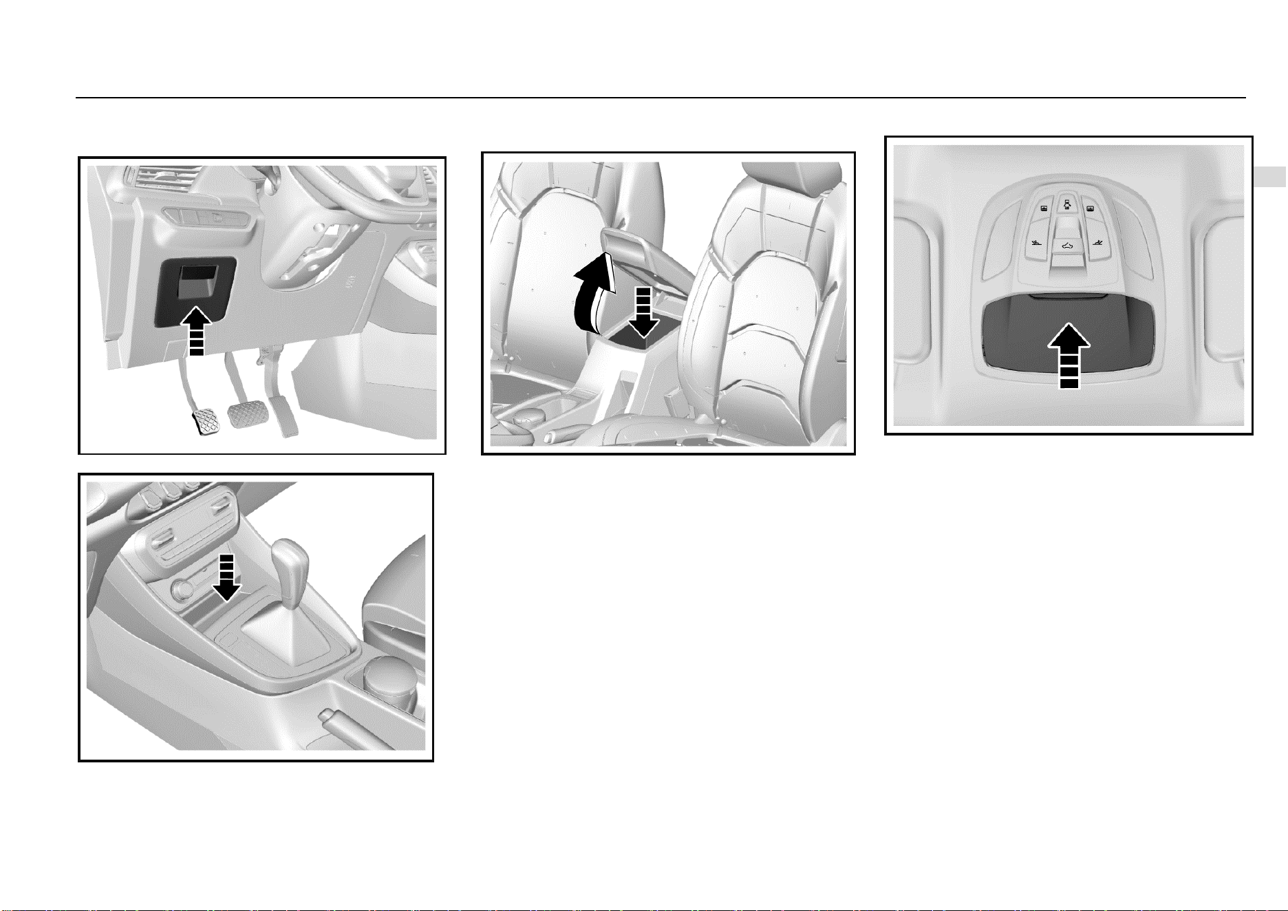
Storage 43
3
Storage
Storage Box
Instrument Panel Left Storage Box
Instrument Panel Central Storage Box
The storage box is under the air-conditioning control panel.
Armrest Storage Box
It is located between the front seats. Pull up the storage box
cover to open it.
Close the storage box cover after using the box.
Glasses Box*
If equipped, the glasses box is located on the roof.
As shown in the figure, press the outer cover, and the
glasses box will pop up automatically. Close the glasses box
after use.
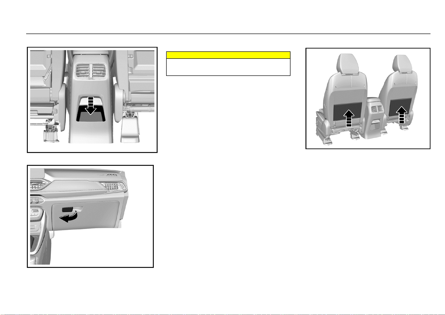
44 Storage
Console Storage Box*
It is behind the armrest box.
Glove Box
Pull the handle outward to open it. To close, push and fasten
the glove box door inward.
Warnings
Keep the glove box door closed when the vehicle is
running to reduce the injury risks in case of accidents
or emergency braking.
Map Pocket
The map pocket is located on the backside of the front seat
backrest.
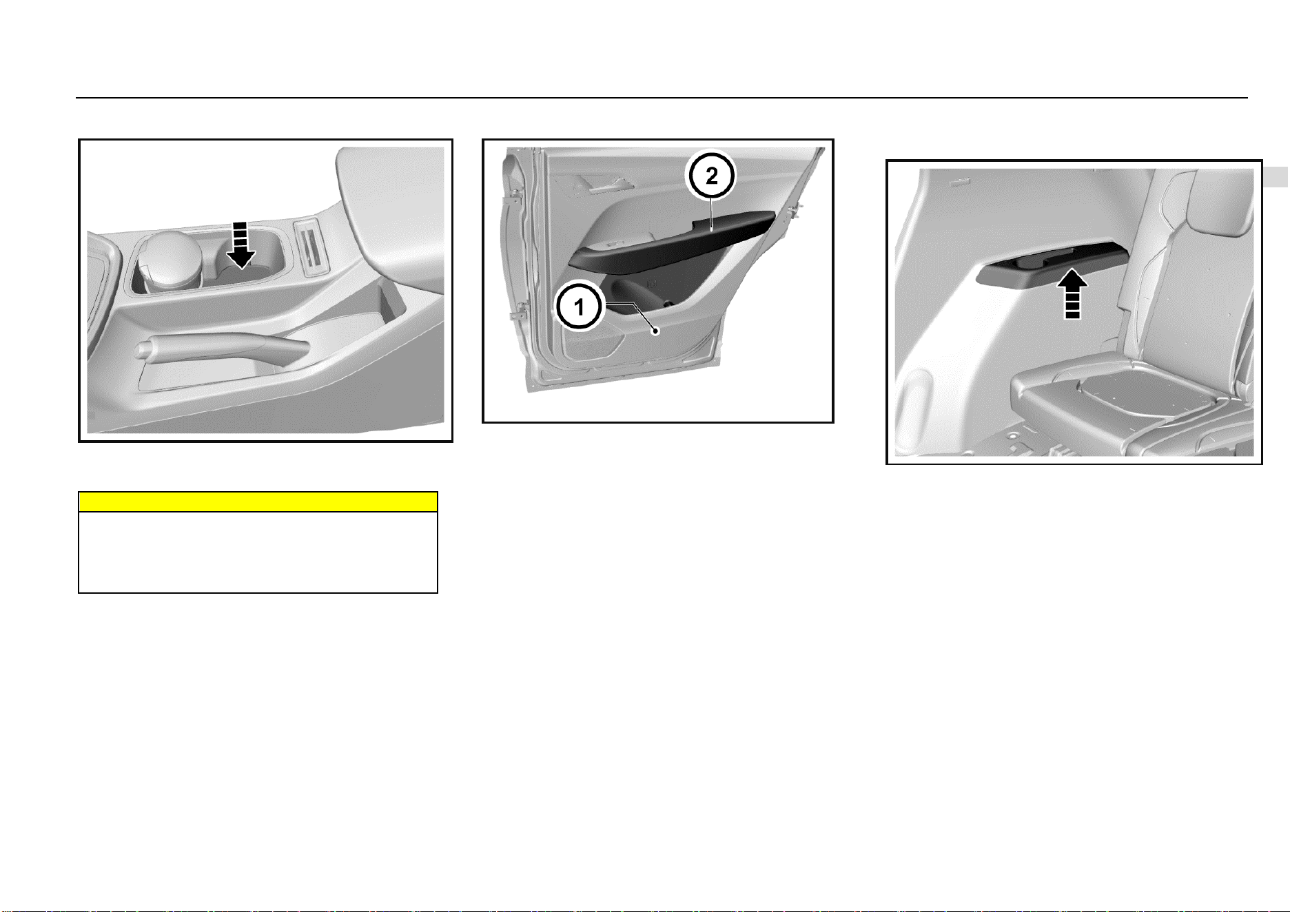
Storage 45
3
Storage
Cup Holder
The cup holder is located on the console between the front
seats. There are 2 cup holders on the rear row seat middle
armrest.
Warnings
When the vehicle is running, it is forbidden to place a
container that contains fluid but is not covered in the
cup holder. If the fluid spills out, scald may be caused,
or you may lose control on the vehicle due to
distraction, leading to an accident.
Door Storage Groove and Armrest
The door storage groove and armrest are located on inner
side of the door panel.
Rear Side Wall Storage Groove and
Armrest
They are located on the left and right rear side walls of 7-
seat models.
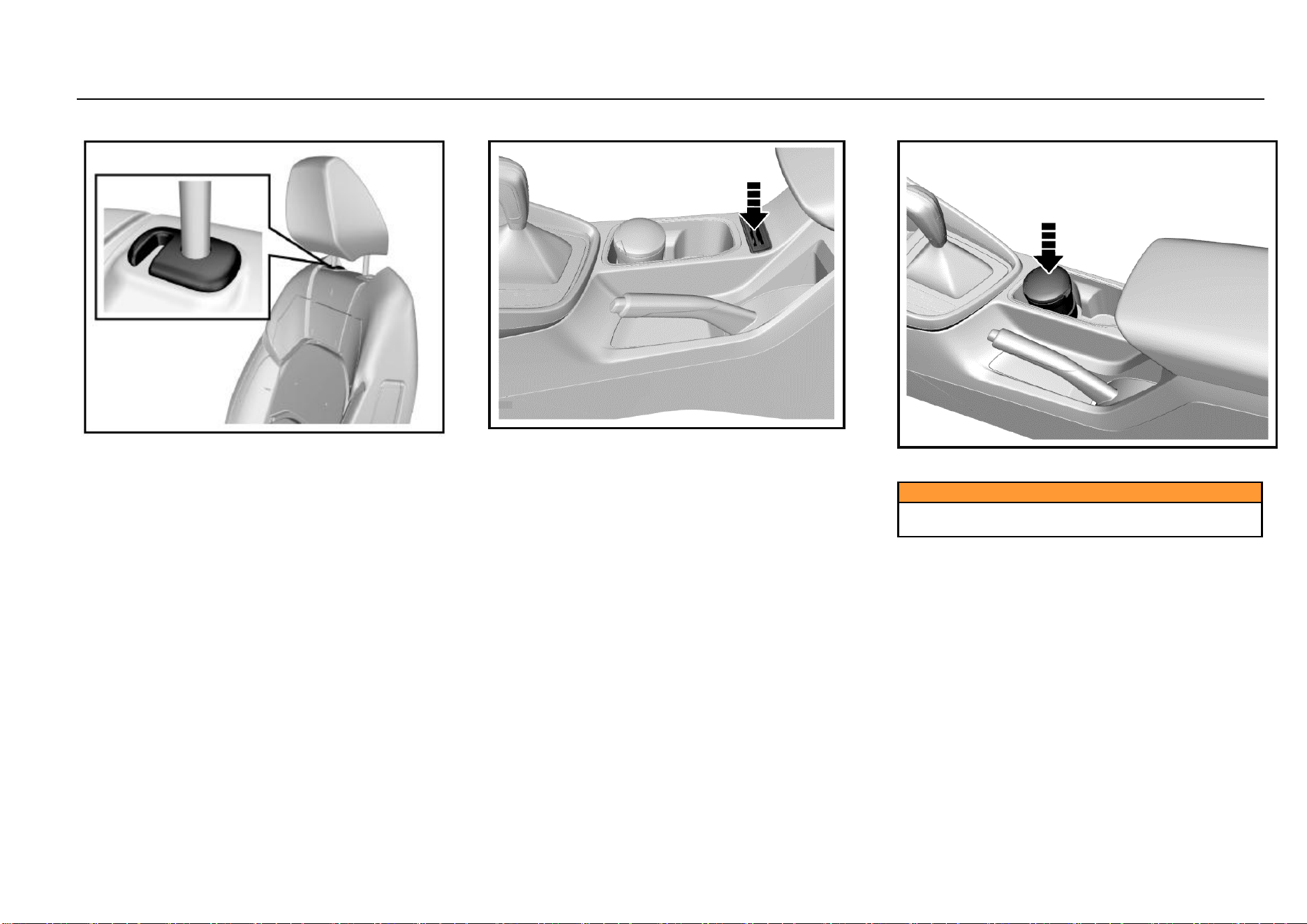
46 Storage
Backrest Hook
On the junction of each seat backrest and headrest, there is
a hook. You can hang a shopping bag or other suitable
object on the hook according to the demand.
Card Slot
On the console, there is a card slot for card placing.
Ashtray*
The ashtray can be moved for use. You can put it in the cup
holder. Open its cover for use.
Caution
The ashtray can only be used for containing cigarette
ash not combustible rubbish.
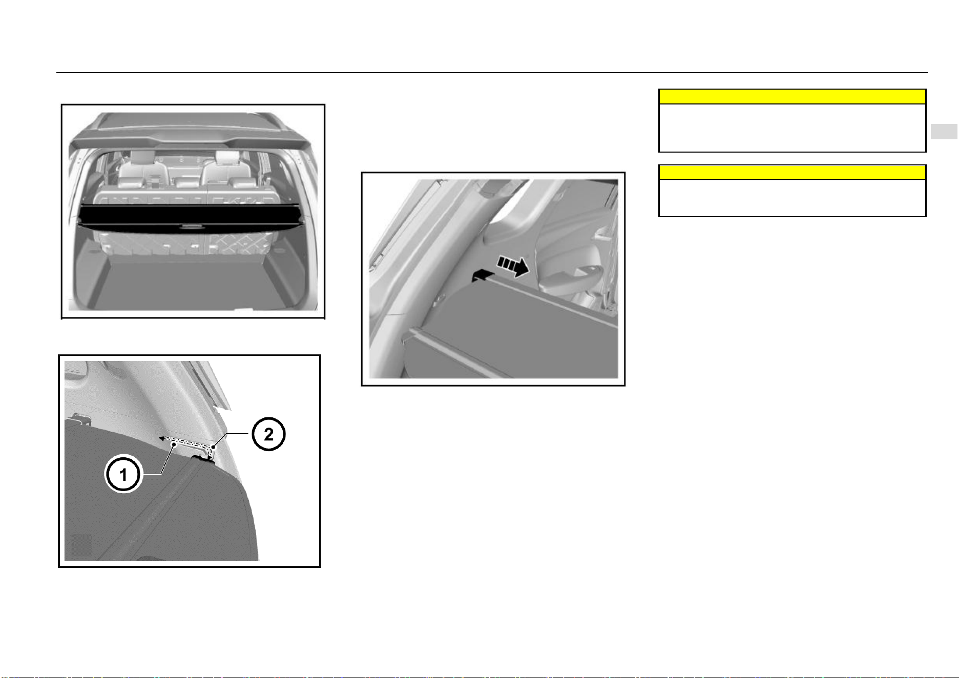
Storage 47
3
Storage
Luggage Compartment Cargo Cover*
The cover is used to shield the objects in the luggage
compartment.
Packing Up Luggage Cover
As shown in the figure, release the luggage cover plates
from the guide slots on both sides of the luggage
compartment, and the cover will retract automatically. To
deploy the luggage cover, pull the luggage cover from the
recoiler, and clamp the two ends of cover plate into the
guide slots on both sides of the luggage compartment.
Luggage Cover Removal
As shown in the figure, press the caps on both ends of the
luggage cover recoiler toward the middle to remove the
luggage cover from the vehicle.
To install the cover, press the caps on both ends toward to
the middle, and align the caps to the slots and then release
the caps to fix the recoiler in the slots.
Warnings
Do not place any object on the luggage compartment
cargo cover. On one hand, the luggage cover cannot
bear loads; on the other hand, the object may hurt
occupants under emergencies.
Warnings
Please place and fix the removed luggage cover
properly; otherwise, the removed luggage cover may
hurt occupants under emergencies.
48 Storage
Roof Rack
The roof rack is an external trim item. To avoid damaging
the vehicle, please do not use the rack to load heavy
objects.
Load Information
The heavy objects inside the luggage compartment
shall be placed close to the backrest. Make sure that
the backrest is fastened. If objects need to be piled in
layers, heavy ones shall be placed in the bottom.
Objects scattered in the luggage compartment shall
be fixed to prevent them from sliding.
The loaded object shall not be higher than the upper
edge of the backrest.
Any object shall not be placed on the luggage cover
or the instrument panel. It is forbidden to cover the air
bag or other parts on the instrument panel.
The objects loaded shall neither hinder the operation
of pedals, parking brake and shift lever nor limit the
free movement of the driver. Do not put any object not
fixed in the vehicle.
Do not drive the vehicle when the liftgate open.
Warnings
It is forbidden to place a cigarette lighter, propane gas
cylinder, perfume or other combustible/explosive
materials in the vehicle. These articles may be on fire
or explode when the vehicle is under high temperature
for a long time.

Instruments and Controls 49
4
Instruments and Controls
Instruments and Controls
Instrument Panel ............................................................. 50
Controls ........................................................................... 51
Horn ....................................................................... 51
Steering Wheel Adjustment ................................... 52
Front Windshield Wiper and Washer ..................... 52
Rear Windshield Wiper and Washer* ..................... 53
Cigar Lighter .......................................................... 53
Exterior Entertainment Power Outlet* .................... 54
Warning Lamps, Gauges and Indicators ......................... 55
Speedometer ......................................................... 55
Tachometer ............................................................ 55
Fuel Gauge ............................................................ 55
General Odometer ................................................. 55
Small Odometer ..................................................... 56
Engine Coolant Temperature Gauge ..................... 56
Type-I Trip Computer Display Screen .................... 56
Average Fuel Consumption ................................... 57
Instantaneous Fuel Consumption .......................... 57
Fuel Range ............................................................ 57
Adjustment Lever ................................................... 58
Type-II Trip Computer Display Screen ................... 59
Door Ajar Warning Lamp ....................................... 65
Instrument Cluster Display Brightness Adjustment 65
Type-I Trip Computer Display Screen Switch ........ 67
Control Indicators ............................................................ 68
Type-I Instrument Cluster ...................................... 68
Type-II Instrument Cluster ..................................... 70
Turn Signal Lamp/Hazard Warning Indicator ......... 71
Engine Oil Pressure Too Low Warning Lamp ........ 72
Charging System Warning Lamp ........................... 72
Coolant Temperature Too High Warning Lamp ..... 73
Front Fog Lamp Indicator* ..................................... 73
Rear Fog Lamp Indicator ....................................... 73
Headlamp High Beam Indicator ............................. 73
Position Lamp Indicator ......................................... 74
Engine Malfunction Indicator Lamp (MIL) .............. 74
ABS Fault Warning Lamp ...................................... 74
EPS Fault Warning Lamp ...................................... 75
Airbag Fault Warning Lamp ................................... 75
Brake System/EBD Warning Lamp ........................ 76
Engine Immobilizer System Indicator ..................... 77
Driver Fasten-Seat-Belt Warning Lamp ................. 77
Front Passenger Fasten-Seat-Belt Warning Lamp*78
ESC Fault Warning Lamp ....................................... 80
ESC OFF Indicator ................................................. 80
Transmission Fault Warning Lamp* ....................... 80
Cruise Control System Working Condition Indicator*
............................................................................... 81
TPMS Fault Indicator* ............................................ 81
Reverse Sensor* .............................................................. 82
Reverse Video Display* .......................................... 82
Parking Assist System* .................................................... 84
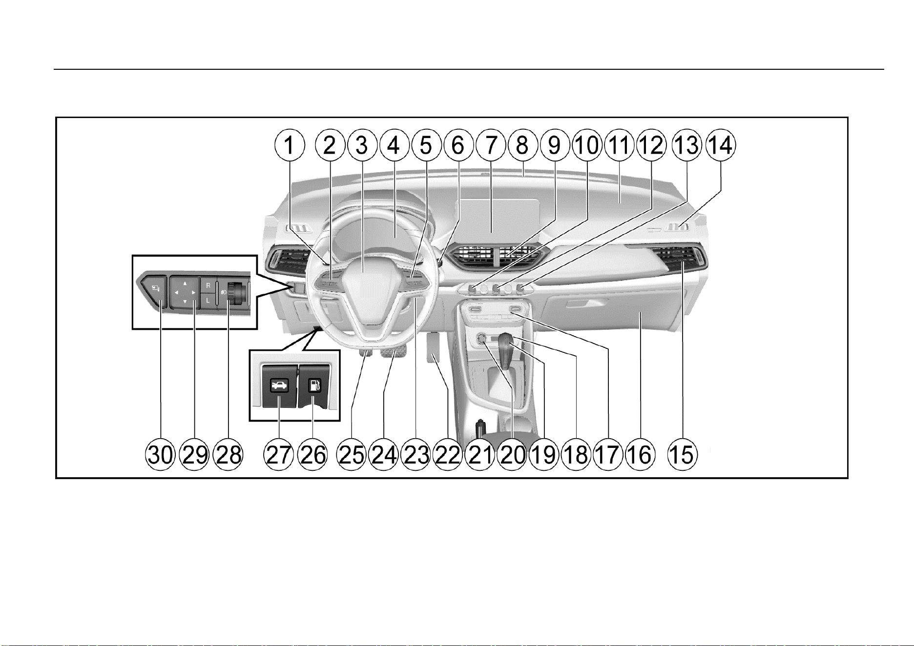
50 Instruments and Controls
Instrument Panel
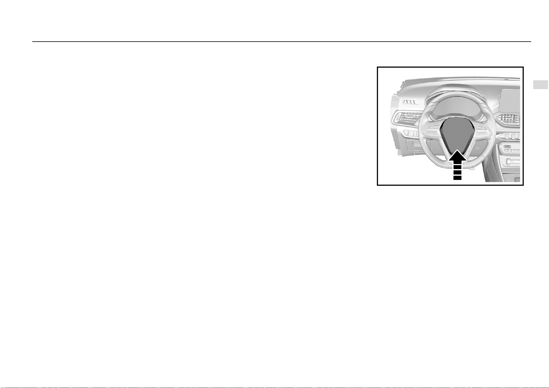
Instruments and Controls 51
4
Instruments and Controls
1. Vehicle lamp and turn signal lamp switch
2. Cruise control system control button*
3. Airbag - driver/horn switch
4. Instrument cluster
5. Audio system control button*
6. Wiper and washer switch
7. Vehicle audio
8. Front air outlet
9. Central air outlet
10, Central door lock switch
11. Front airbag - passenger*
12. Hazard warning lamp switch
13. ESC OFF switch
14. Defrost air outlet for front
15. Side air outlet
16. Glove box
17. Air conditioner control panel
18. Exterior entertainment power outlet*
19. Shift lever
20. Cigar lighter
21. Parking brake lever
22. Accelerator pedal
23. Ignition switch*
24. Brake pedal
25. Clutch pedal
26. Fuel filler cap release lever
27. Hood release lever
28. Headlamp adjustment knob
29. Electrically operated outside rearview mirror adjustment
switch
30. Outside rearview mirror electric folding switch*
Controls
Horn
Press the switch on the steering wheel to blow the horn.
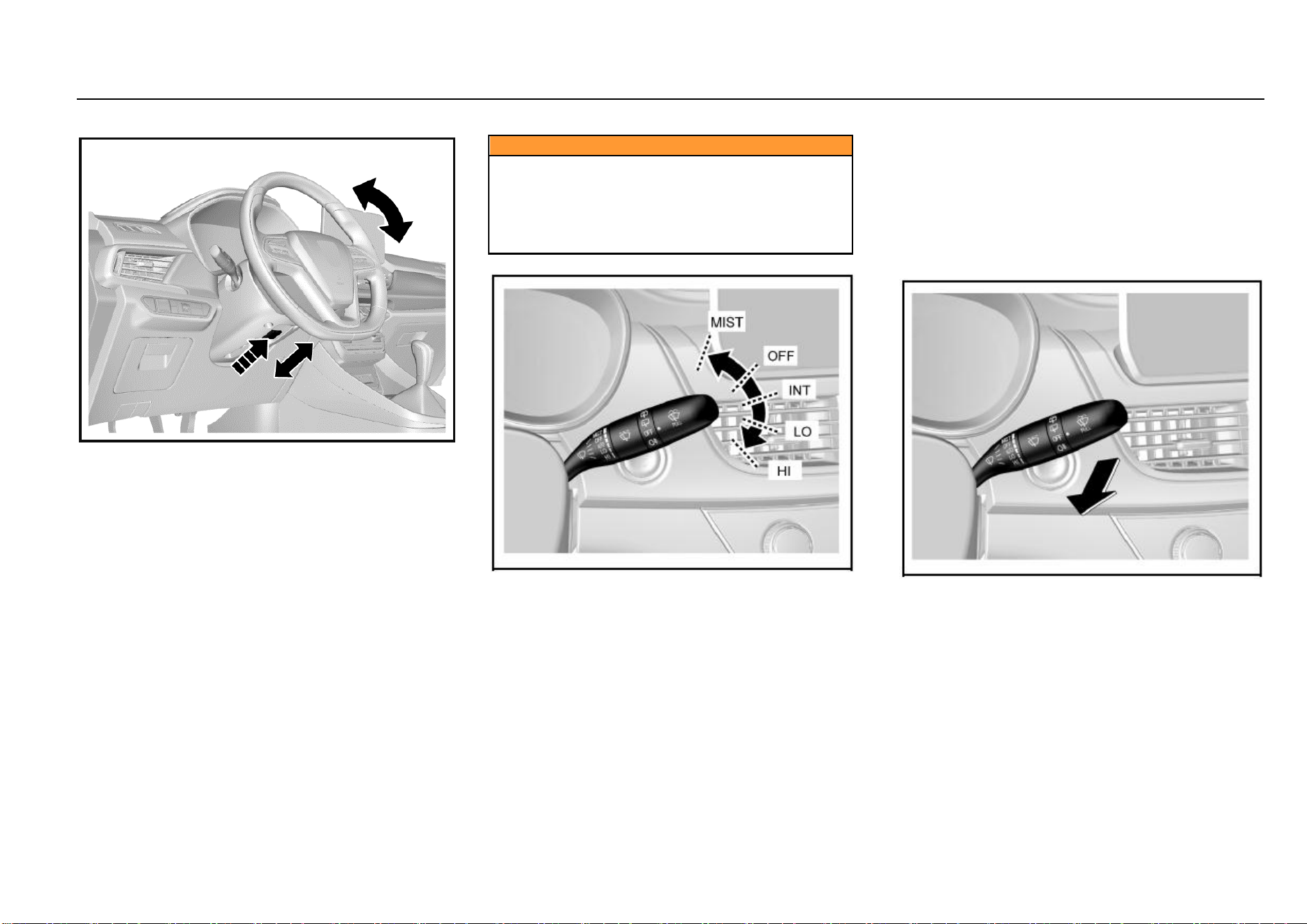
52 Instruments and Controls
Steering Wheel Adjustment
It is only allowed to adjust the steering wheel after the
vehicle has fully stopped. The steering wheel can tilt
upwards/downwards.
If you need to adjust the steering wheel:
1. As is shown in the figure, push the steering wheel
adjustment lever outward first;
2. Adjust the steering wheel to the desired position and then
pull back the adjustment lever to lock the steering
wheel;
3. Check and confirm that the steering wheel has been
locked firmly.
Caution
The driver must keep absolute control of the steering
wheel during driving.
It is not allowed to adjust the steering wheel while the
vehicle is running.
Adjusting the steering wheel during driving can cause
the vehicle out of control.
Front Windshield Wiper and Washer
To use the front windshield wiper, turn on the ignition switch
first and then push the windshield wiper/washer control
lever. The front windshield wiper has the following 5 working
positions:
MIST: Push the control lever up once and the wiper wipes
once.
OFF: Turn the system off.
INT: Push the control lever down to this position and the
wiper wipes intermittently.
LO: Push the control lever down to this position and the
wiper wipes continuously at a low speed.
HI: Push the control lever down to this position and the wiper
wipes continuously at a high speed.
The intermittent wiping (INT) speed is adjustable and to
select the desired speed, just turn the circular knob in the
middle of the control lever.
To spray cleaning fluid on the front windshield:
Turn the ignition switch to “ON (connected)” position;
Pull the windshield wiper/washer control lever
towards the steering wheel.
Keep pulling the control lever for more than 1s or so—the
washer sprays cleaning fluid to the windshield and works for
3 cycles or until the control lever is released.
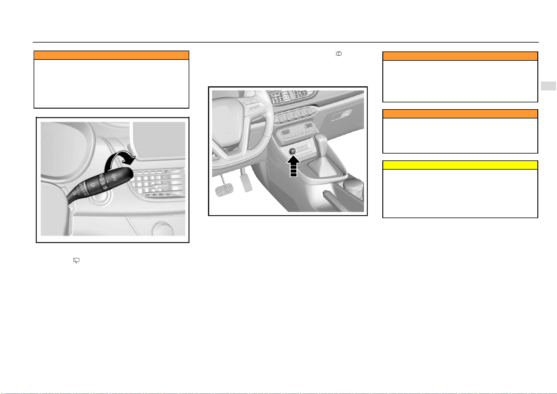
Instruments and Controls 53
4
Instruments and Controls
Caution
● Blurred view of the driver can lead to accident and
cause personal injuries and damage to the vehicle or
other properties.
● In cold weather, if the wiper gets frozen, before using
the wiper, please spray warm water on the frozen area
to deice and then wipe off the water immediately to
prevent icing.
Rear Windshield Wiper and Washer*
To use the rear windshield washer, turn the ignition switch
to “ON” position first and then turn the rear wiper and washer
switch knob to .
Turn the rear wiper and washer switch knob to and the
water pump sprays water to the rear windshield
immediately. Release the knob and the pump stops
spraying.
Cigar Lighter
The cigar lither is installed in the instrument panel central
storage box. To use the cigar lighter, turn the ignition switch
to ACC (electrical accessories) or ON (connected) position
and then fully push the cigar lighter in. The cigar lighter will
pop out automatically as it is well prepared.
Caution
The cigar lighter barrel becomes very hot while
working.
Do not touch the cigar lighter or allow the child to
operate or play with it.
Hot metal can cause personal injuries or damage to
the vehicle or other properties.
Caution
An overheated cigar lighter can damage the heating
element as well as the lighter itself. Do not press the
cigar lighter while it is heated, otherwise the lighter
can become overheated. Do not use the cigar lighter
receptacle for power supply purpose.
Warning
If you leave flammables or explosives in the vehicle,
for example, leaving a lighter in the vehicle on a
summer day, the temperature in the passenger
compartment and the luggage compartment will
increase, causing explosion or fire accident as a
result. Therefore, please ensure that no flammables or
explosives are left in the vehicle.
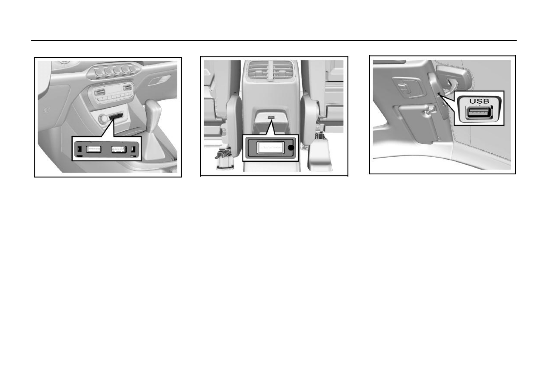
54 Instruments and Controls
Exterior Entertainment Power Outlet*
The entertainment power outlet is located below the air
conditioner control panel.
The USB interface can be used for cellphone charging and
connection of audio files.
The charging power outlet is unavailable if the ignition
switch is turned off.
For other information about the USB interface, please refer
to the Audio System Specifications provided together with
the vehicle.
Rear Accessory USB Power Outlet*
The second-row USB power outlet (5V/2A) is located at the
rear end of the console and it can be used for cellphone
charging. The power outlet is unavailable if the ignition
switch is turned off.
If equipped, the third-row USB power outlet is located at the
third-row seat right armrest.
Driving Recorder USB Power Outlet
The driving recorder is located at the bottom of the inside
rearview mirror and it can provide power supply for your
driving recorder.
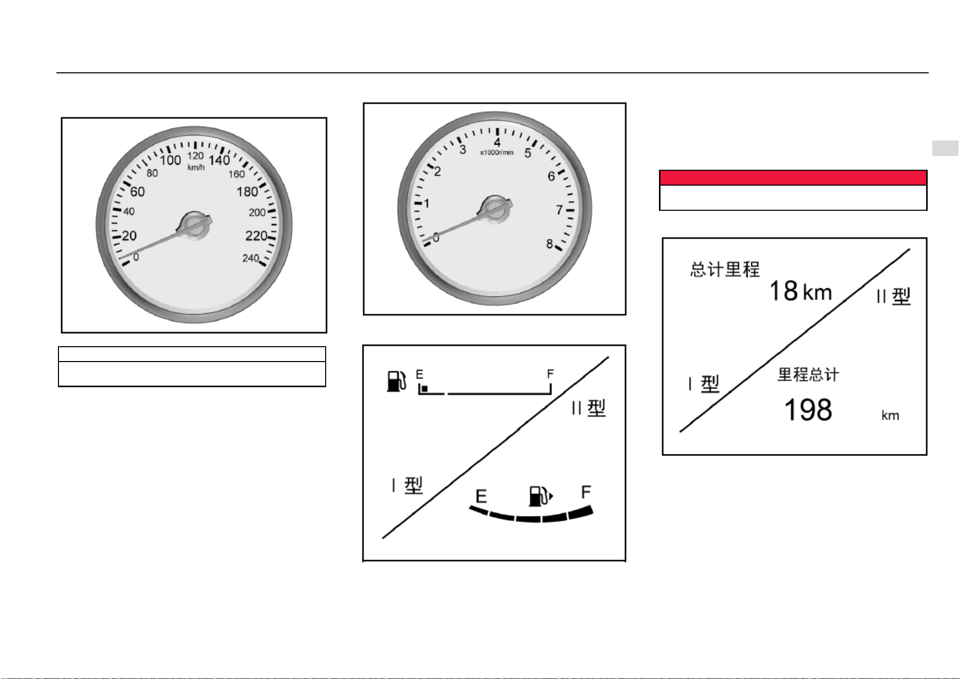
Instruments and Controls 55
4
Instruments and Controls
Warning Lamps, Gauges and Indicators
Speedometer
It displays the vehicle speed.
Note
Please keep the speed within the limit when driving in
a speed limit zone.
Tachometer
It displays the engine crankshaft revolutions per minute.
Fuel Gauge
It displays the fuel level in the fuel tank.
If the fuel level in the fuel tank is too low, the control indicator
will illuminate. Please add fuel immediately. It is strictly
prohibited to use up the fuel in the fuel tank.
As some fuel remains in the fuel tank, the adding amount
can be less than the fuel tank capacity. During braking,
acceleration or cornering, as the fuel in the fuel tank shakes,
indication on the fuel gauge fluctuates.
Danger
Before adding fuel, please do stop the vehicle and
shut down the engine.
General Odometer
It displays the total accumulated kilometers of the vehicle.
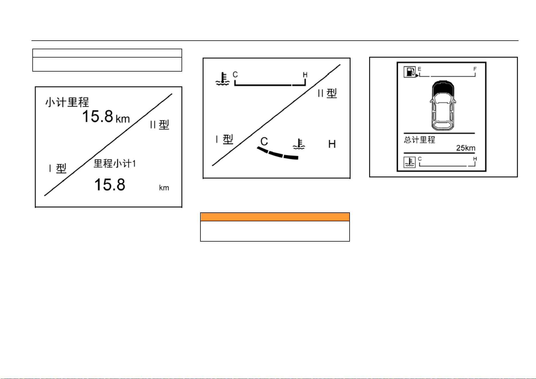
56 Instruments and Controls
Note
It is lawfully forbidden to adjust the odometer for
illegal purpose.
Small Odometer
It shows vehicle kilometers for a driving trip
after it has been reset to zero. In this mode, long press the
adjustment lever to clear the trip distance.
You can clear the trip distance when it is displayed on the
small odometer. To do this, long press “OK” button on the
steering wheel if the vehicle is of high configuration; long
press the instrument cluster adjustment lever if the vehicle
is of low configuration.
Engine Coolant Temperature Gauge
It displays the temperature of the engine coolant.
“C” means “cold state” and “H” means “hot temperature”;
when the coolant temperature gauge indicates within the
red area, it indicates the engine is overheated. Please shut
down the engine immediately for inspection.
Caution
If the engine coolant temperature is too high, please
stop the vehicle, shut down the engine and inspect the
coolant level.
Type-I Trip Computer Display Screen
The trip computer monitor is located between the
tachometer and the speedometer. It can display fuel gauge,
engine coolant temperature gauge, general odometer, small
odometer, fuel range, instantaneous fuel consumption,
average fuel consumption, etc., depending on the vehicle
configuration.
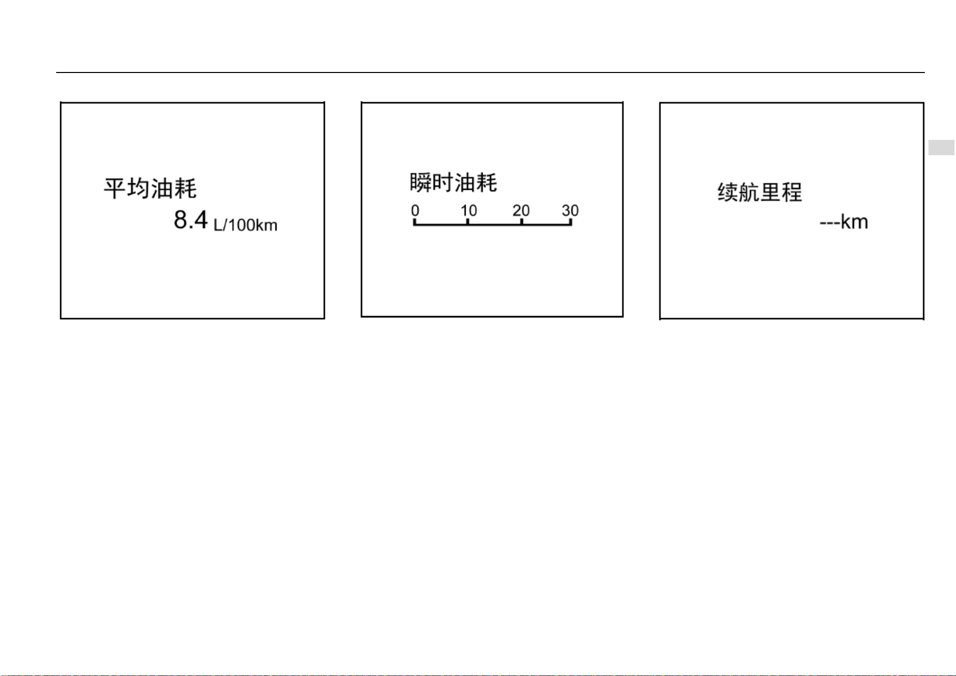
Instruments and Controls 57
4
Instruments and Controls
Average Fuel Consumption
It indicates the average fuel consumption given for
reference by the driver in the current driving mode, under
the current driving cycle. Average fuel consumption can
help the driver develop a good driving habit and it indicates
in L/100 km.
In different driving modes, the reference average fuel
consumption is different.
Driving mode: driving conditions such as driving in urban
area, high-speed driving, driving at different constant
speeds, acceleration/deceleration condition, driving at the
same speed and with different gears engaged, etc.
when driving on a slope (up or down) for a long distance, or
in case of traffic jam lasting for a long time, the fuel
consumption shown on the average fuel consumption
gauge may be higher or lower than normal. This depends
on the current driving condition and it is a normal
phenomenon.
Instantaneous Fuel Consumption
It indicates the reference fuel consumption (in L/100 km) in
the current accelerator control state and under the current
driving cycle.
Driving cycle: The period from starting the engine to shutting
it down represents a driving cycle.
The instantaneous fuel consumption changes real-time as
the throttle valve opening, revolution speed and vehicle load
change.
Fuel Range
It indicates the reference mileage the vehicle can
continuously run for with the current remaining fuel amount.
It changes as the fuel consumption under the current driving
condition changes.
Fuel range is for reference only. Please add fuel as soon as
possible the fuel level low indicator illuminates.
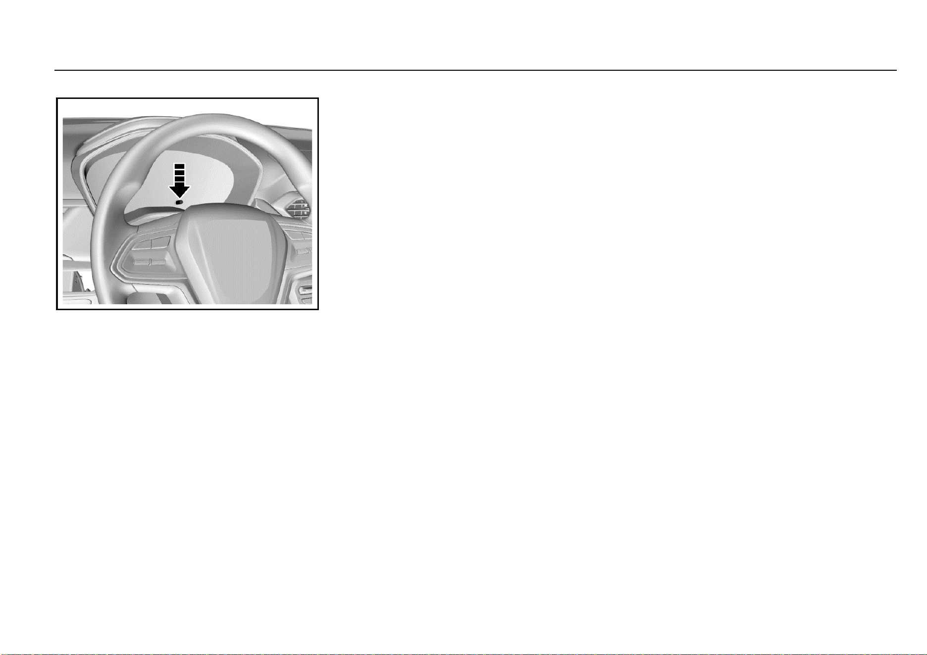
58 Instruments and Controls
Adjustment Lever
Short press or long press the adjustment lever to switch
among different screens or carry out zeroing.
Long press means press for over 2s and short press means
press for 2s or less.
Rotate the adjustment lever to adjust the display brightness
of the instrument cluster.
For more details, please refer to “Display Screen Mode
Switch”.
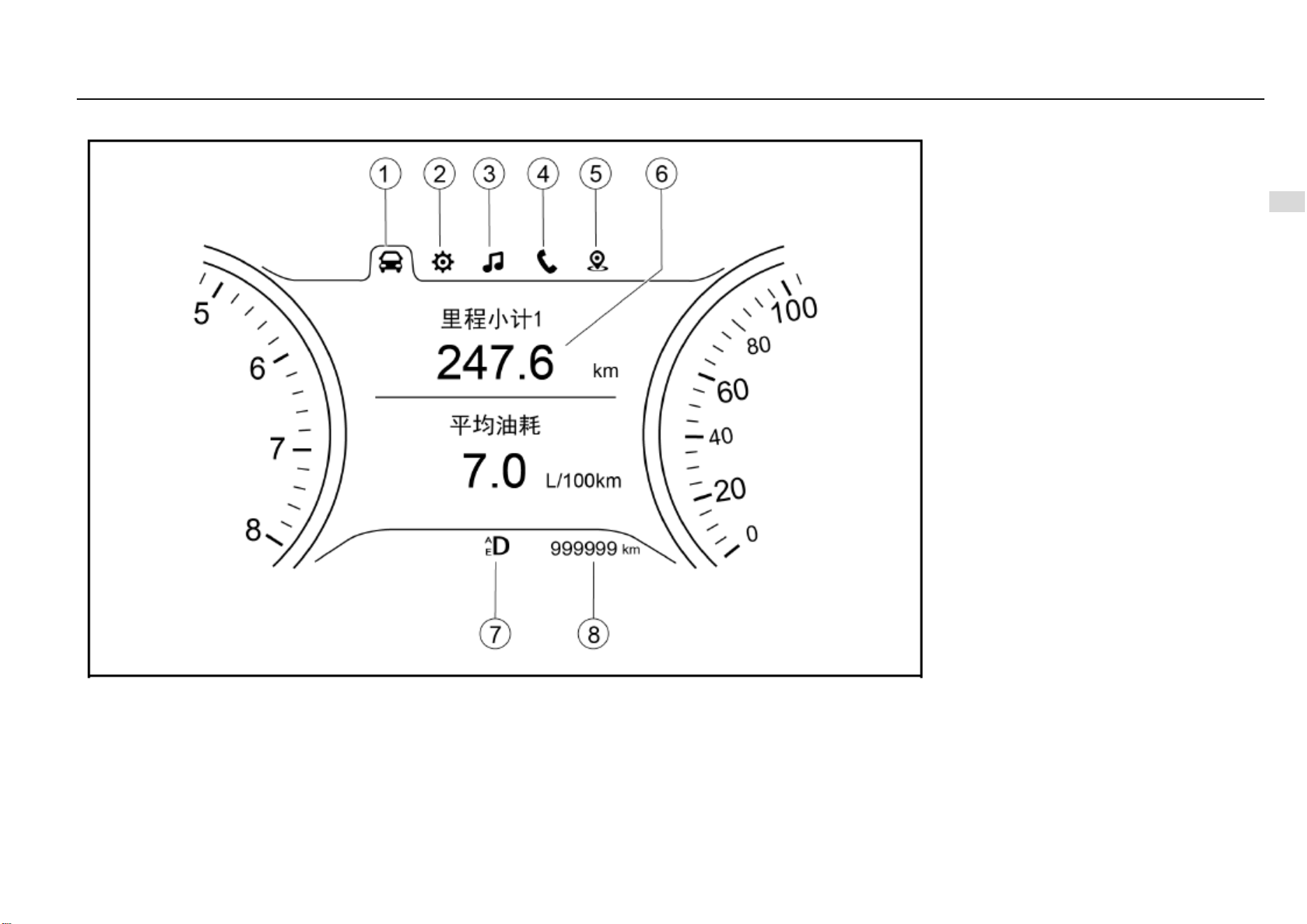
Instruments and Controls 59
4
Instruments and Controls
Type-II Trip Computer Display Screen
1. Trip computer information option
2. Vehicle information setup option
3. Multimedia information display option
4. Bluetooth telephone information display option
5. Navigation information display option
6. Display zone
8. General odometer
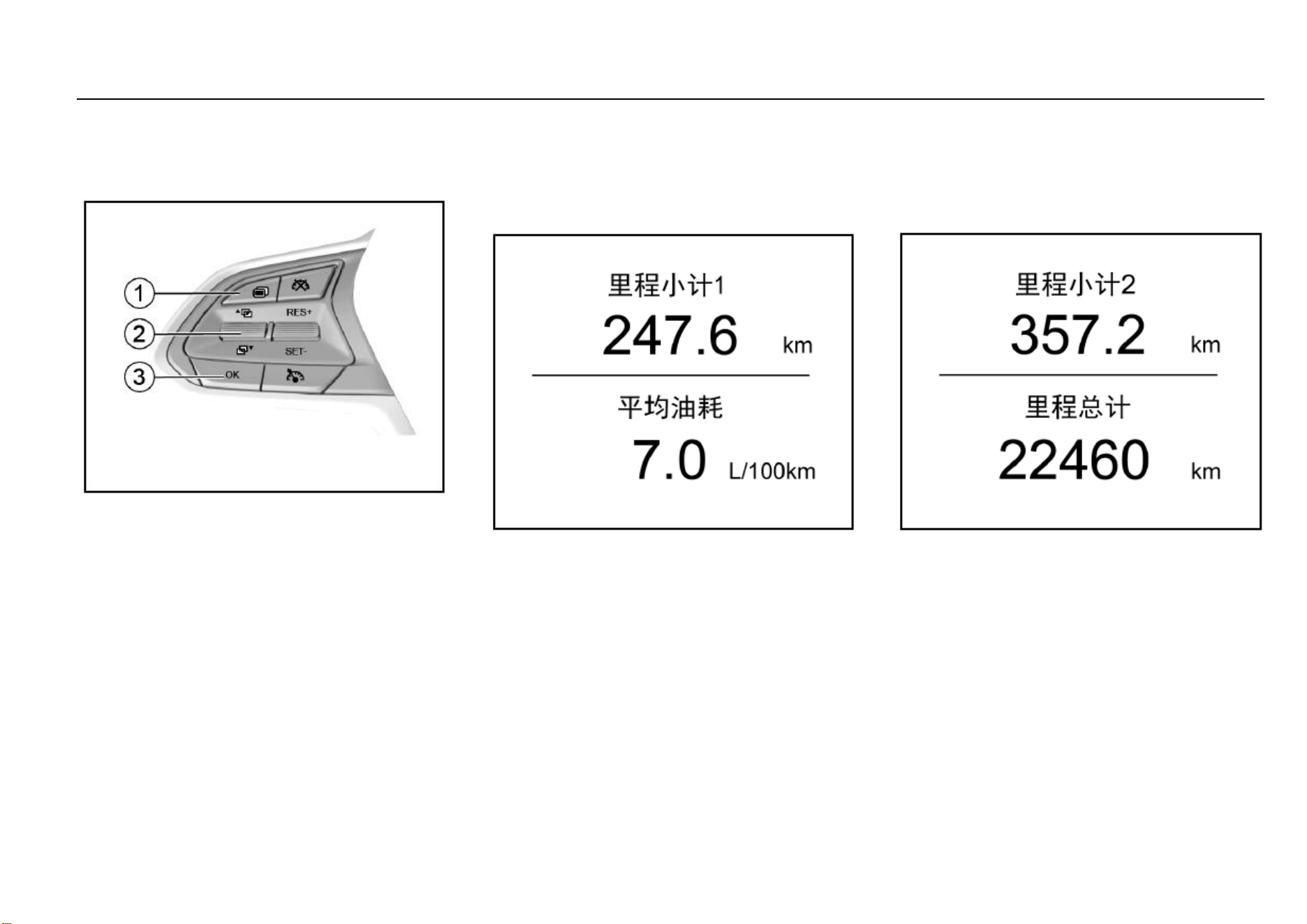
60 Instruments and Controls
Instrument Cluster Control Button*
Type-II trip computer display screen can be controlled with
the control button on the steering wheel. Only when the
ignition switch is turned to ON can the instrument cluster be
controlled.
1. Option switch button
It is used to switch among different display screens.
2. Up/down selection button
Pull it up or down to make selection or adjustment.
3. Confirm button (OK)
It is used to confirm the setup or to clear the trip
mileage or the average fuel consumption. The confirm
button can be operated in two ways: short press (<2S)
and long press (≥2S).
Trip Computer Information Option
Choose this option to indicate driving information such as
odometer, average fuel consumption, current vehicle
speed, instantaneous fuel consumption, driving time, fuel
range, tire pressure, etc. Pull the up/down selection button
to switch among the following interfaces:
Interface 1—Trip Mileage 1/Average Fuel Consumption
The first trip mileage and the average fuel consumption
within the recent driving distance are shown.
Average fuel consumption is shown in L/100 km and it can
help the driver develop a good driving habit.
In different driving modes, the reference average fuel
consumption is different. These driving modes include
driving in urban area, high-speed driving, driving at different
constant speeds, acceleration/deceleration condition,
driving at the same speed and with different gears engaged,
etc.
On the current operation interface, if you long press “OK”,
the trip mileage 1 and the average fuel consumption will be
cleared. After clearing, no average fuel consumption will be
shown until the vehicle has run for 0.1 km.
Fuel consumed as the vehicle is idling is not included in
calculation of the average fuel consumption.
Interface 2—Trip Mileage 2/Total Mileage
The second trip mileage and the total mileage are shown.
On the current operation interface, if you long press “OK”,
the trip mileage 2 will be cleared.
The total mileage cannot be cleared. The total mileage
keeps identical to general odometer indication shown at the
lower half of the LCD.
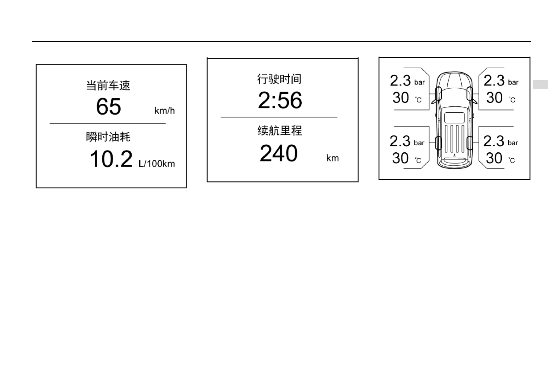
Instruments and Controls 61
4
Instruments and Controls
Interface 3—Current Vehicle Speed/Instantaneous Fuel
Consumption
The current vehicle speed indicates the speed at which the
vehicle is currently running.
Instantaneous fuel consumption indicates the reference fuel
consumption (in L/100 km) in the current accelerator control
state and under the current driving cycle. If the current
vehicle speed is extremely low, the instantaneous fuel
consumption will show in L/h (liter per hour).
The instantaneous fuel consumption changes real-time as
the throttle valve opening, revolution speed and vehicle load
change.
Interface 4—Driving Time/Fuel Range
Calculation of the driving time starts as the vehicle starts
running and ends as the vehicle stops. The indication can
be 23 hours plus 59 minutes at maximum.
After the driving time reaches the maximum record value, or
when the battery gets disconnected, or the engine flameout
condition lasts for 2 hours, the driving time will clear
automatically and calculation starts anew.
The displayed fuel range is calculated based on the current
fuel consumption and the fuel amount left in the fuel tank. It
changes as the driving condition changes. When the fuel
level low warning indicator illuminates, “fuel insufficient, add
fuel” will appear in the fuel range indication area. If you long
press “OK” on the current interface, the driving time will be
cleared, while the fuel range cannot be cleared.
Interface 5—Tire Pressure Indication
The tire pressure monitor system (TPMS) displays the
current pressure and temperature of the four tires
respectively.
When the system detects tire pressure low or high, it gives
a prompt, asking you to adjust the tire pressure in time. For
the standard tire pressures, please refer to “Technical
Data”.
If the tire temperature value becomes extremely great, for
example, when you are driving down a slope and applies
the brake frequently, please stop the vehicle to cool down
the tires. If the shown tire temperature value becomes
abnormal, please contact the Service Center as soon as
possible for inspection and repair.
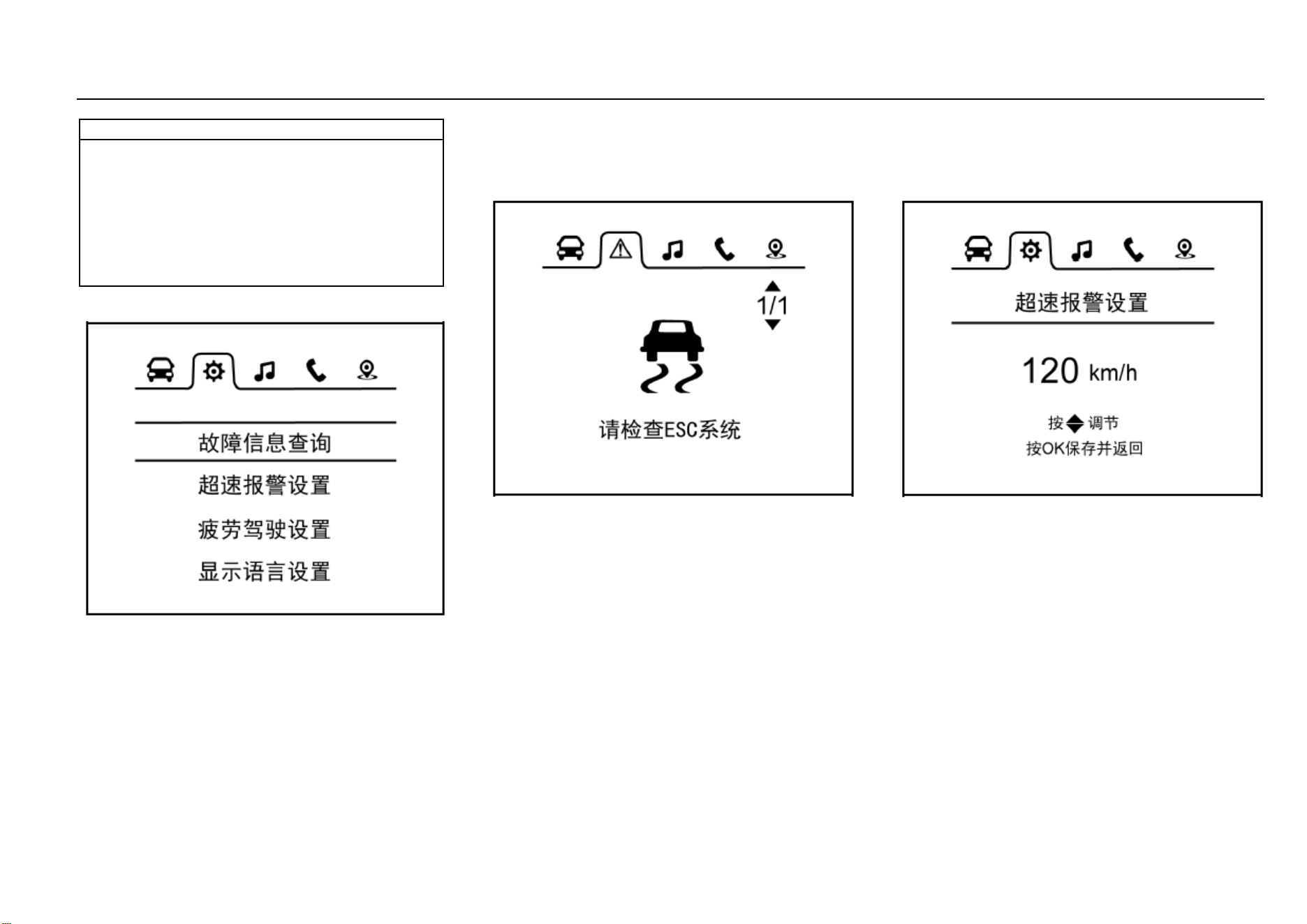
62 Instruments and Controls
Note
Please keep the tire pressure within the reference
range, otherwise the tire service life and vehicle
controllability can be reduced, or flat tire can happen
which is very dangerous. Please do not continue
driving if the tire temperature is extremely high. Once
overheated, the brake may fail to provide sufficient
braking force and the tire may become flat. Please
stop the vehicle as soon as possible to cool down the
tire and carry out inspection.
Vehicle Information Setup Option
This option allows access to fault information inquiry,
overspeed warning setup, fatigue driving setup and display
language setup.
Pull the up/down selection button and then press “OK” to
enter the interface under this option.
The control button on the steering wheel will be shielded as
a warning message pops out on the display screen. The
control button will give no response even though it is
pressed until the warning message disappears.
Interface 1—Fault Information Inquiry
Press “OK” and you will enter the fault information inquiry
interface. If no fault information is shown, a prompt saying
no fault information exists will appear on the LCD; if any fault
information is shown, you can check it one by one by
pushing the up/down selection button.
Press “OK” to return to the parent directory.
If any fault exists at the time of vehicle start, a fault warning
will appear and last for 5s. Please contact the Service
Center for inspection and repair.
When the icon under this option changes to what is shown
above, it indicates a vehicle fault to which you should keep
alert. Please contact the Service Center in time for
inspection and repair so as to eliminate the safety hazard.
Interface 2—Overspeed Warning Setup
Enter the overspeed warning setup interface and you can
set the overspeed warning speed value. Once the driving
speed exceeds the set value, a text warning message will
appear on the LCD, accompanied by a sound alarm. The
system reminds you that the speed is too high for driving
safety in this way. You can also disable the overspeed
warning function by selecting the corresponding option on
this interface. The overspeed warning function gets disabled
by fault once the battery power is cut off.
Set range of overspeed warning: 30 km/h~ 130 km/h at an
increment/decrement of 5 km/h.
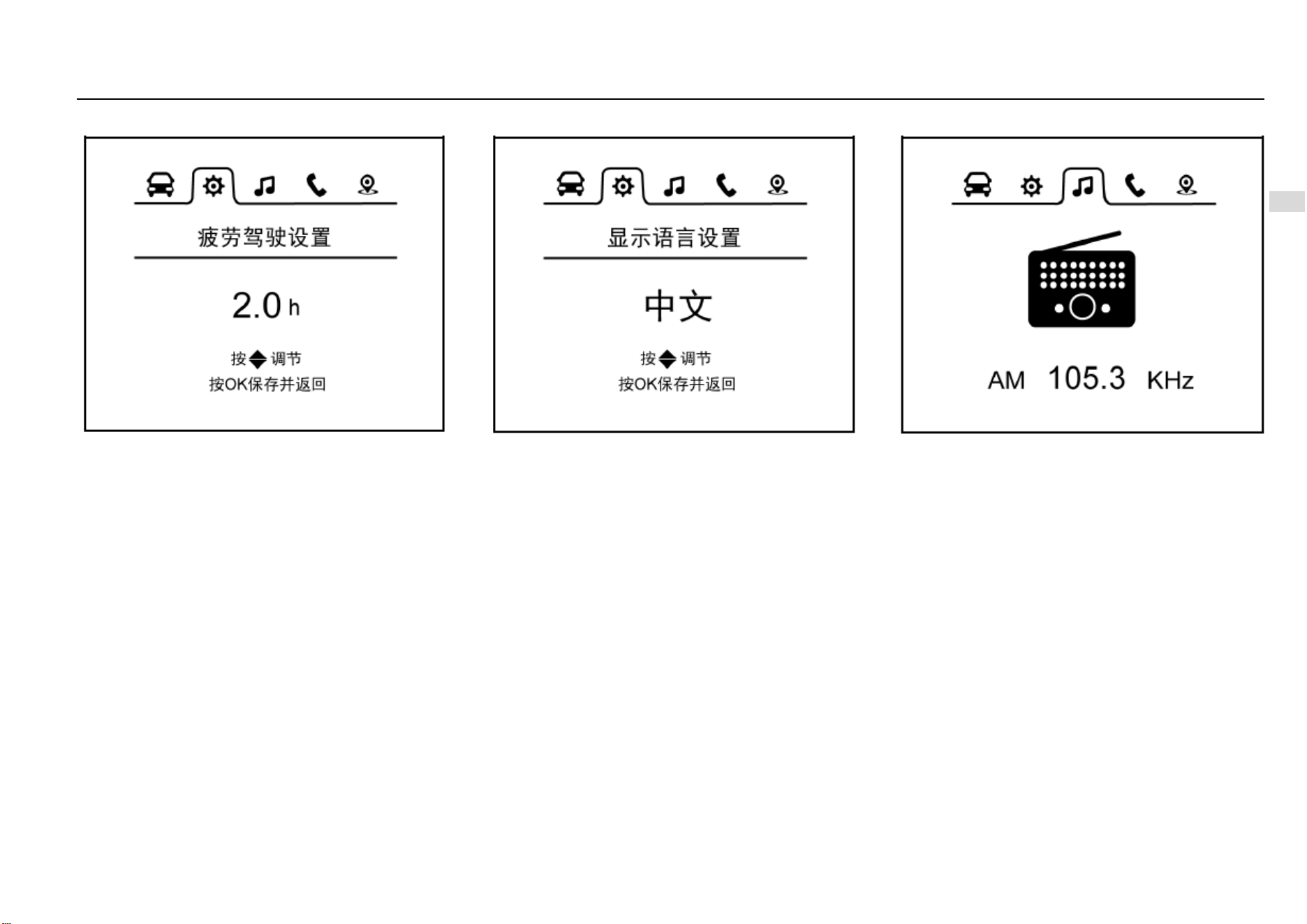
Instruments and Controls 63
4
Instruments and Controls
Interface 3—Fatigue Driving Warning Setup
Enter the fatigue driving function setup interface and you
can make fatigue driving function setup. Once the driving
time reaches or exceeds the set value, a text warning
message will appear on the LCD, accompanied by a sound
alarm. The system reminds you to have a rest if necessary
in this way. You can also disable the fatigue driving function
by selecting the corresponding option on this interface. The
fatigue driving function gets disabled by fault once the
battery power is cut off.
Set range of fatigue driving warning: 1 h~ 4 h at an
increment/decrement of 0.5 h.
Interface 4—Display Language Setup
Enter the display language setup interface and you can set
Chinese or English as the current display language.
Multimedia Information Option
Choose this option and the instrument cluster will show AM,
FM or audio information real-time on the screen. If the
instrument cluster has not connected to the relevant system,
“Connecting Multimedia” will appear on the screen.
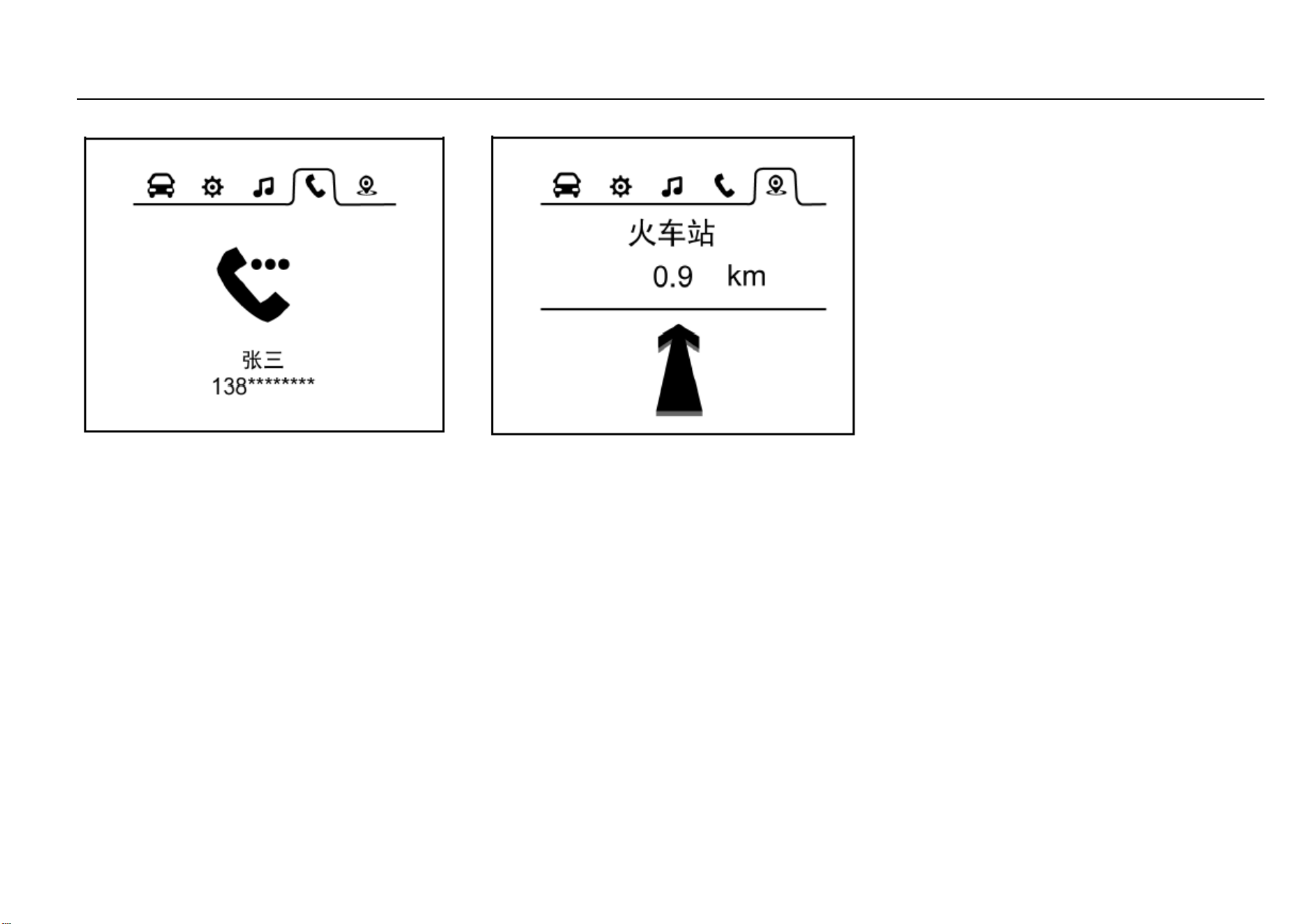
64 Instruments and Controls
Bluetooth Telephone Information Option
Choose this option and the Bluetooth telephone interface
will appear. If the instrument cluster has not connected to
Bluetooth telephone, “Telephone Not Connected” will
appear on the screen. After successful connection,
“Telephone Connected” will appear on the screen.
The instrument cluster will show the current state of
Bluetooth telephone on the screen: “incoming call”,
“outgoing call” and “on the line”.
In addition, the instrument cluster will also show the current
telephone number and name of the contact on the screen.
Navigation Information Option
Choose this option and the instrument cluster will show
“road name”, “destination” “distance information” or
indication icon on the screen, depending on the current
state of the navigation system.
If the instrument cluster has not connected to the navigation
system, “Connecting Navigation” will appear on the screen.
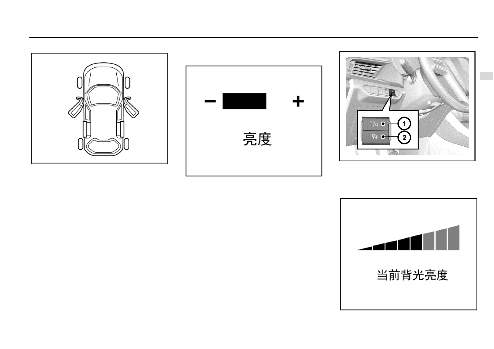
Instruments and Controls 65
4
Instruments and Controls
Door Ajar Warning Lamp
If any door in the front or rear row is ajar or not fully closed,
a warning lamp shaped like the door ajar will illuminate; if
the liftgate is ajar or not fully closed, a warning lamp shaped
like a liftgate ajar will illuminate or flash.
If any door is not fully closed while the vehicle is running at
a speed of ≥10 km/h, a door ajar alarm sound will be issued.
Instrument Cluster Display Brightness
Adjustment
Type-I Instrument Cluster*
Turn the adjustment lever to set the desired display
brightness. After adjustment, if no operation is conducted
within 2s, the system will turn back to the previous interface.
Type-II Instrument Cluster*
For high-configuration models, a backlight brightness
adjustment button is set at the left side of the instrument
panel.
Turn the ignition switch to ON position and then press the
backlight adjustment button to set backlight brightness of
the instrument cluster.

66 Instruments and Controls
As it is shown in the figure, the current backlight brightness
will be shown on the LCD as you make the adjustment. If no
operation is conducted within several seconds, the system
will save the setup and turn back to the previous interface.
When the position lamp is switched on, the backlight
brightness will decrease automatically.
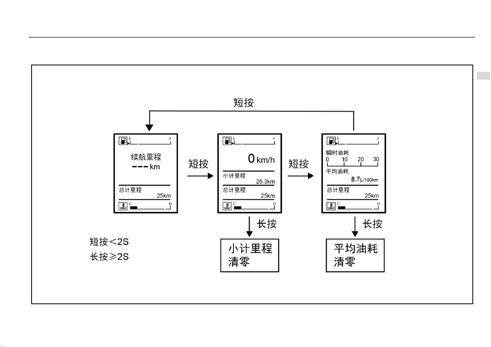
Instruments and Controls 67
4
Instruments and Controls
Type-I Trip Computer Display Screen Switch
If the vehicle is equipped with a Type-I trip computer display screen, you can short press or long press the adjustment lever on the instrument cluster to switch the display modes or conduct
clearing. As it is shown in the figure:
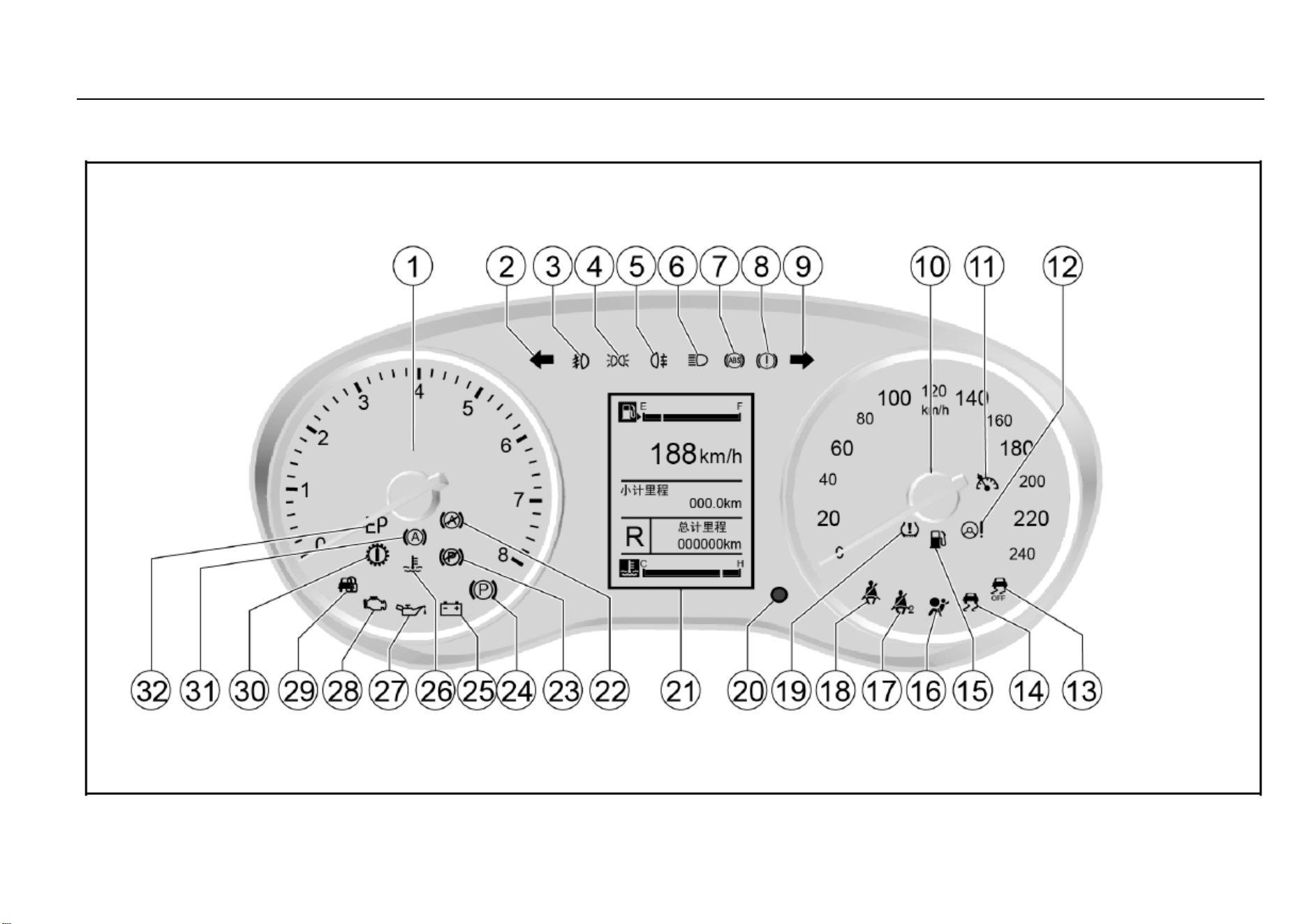
68 Instruments and Controls
Control Indicators
Type-I Instrument Cluster

Instruments and Controls 69
4
Instruments and Controls
1. Engine tachometer
2. Left turn signal lamp/hazard warning indicator
3. Front fog lamp indicator*
4. Position lamp indicator
5. Rear fog lamp indicator
6. Headlamp high beam indicator
7. ABS fault warning lamp
8. Brake system/hand brake indicator/EBD warning lamp
9. Right turn signal lamp/hazard warning indicator
10. Speedometer:
11. Cruise control system working condition indicator*
12. Electronic power steering (EPS) fault warning lamp
13. Electronic stability control (ESC) OFF indicator
14. Electronic stability control (ESC) fault warming lamp
15. Fuel level low warning lamp
16. Airbag fault warning lamp
17. Front passenger fasten-seat-belt warning lamp*
18. Driver fasten-seat-belt warning lamp
19. Tire pressure monitor system (TPMS) fault warning
lamp*
20. Display adjustment lever
21. Trip computer display screen
25. Charging system fault warning lamp
26. Coolant temperature too high warning lamp
27. Engine oil pressure too low warning lamp
28. Engine malfunction indicator lamp (MIL)
29. Engine immobilizer system indicator
30. Transmission fault warning lamp*
After the ignition switch is turned on, as a functional test,
most of the control indicators will illuminate for a short while.
Colors of the control indicators mean:
Red = danger, important reminder
Yellow = warning, information, fault.
Green = activation confirmed.
Blue = activation confirmed.
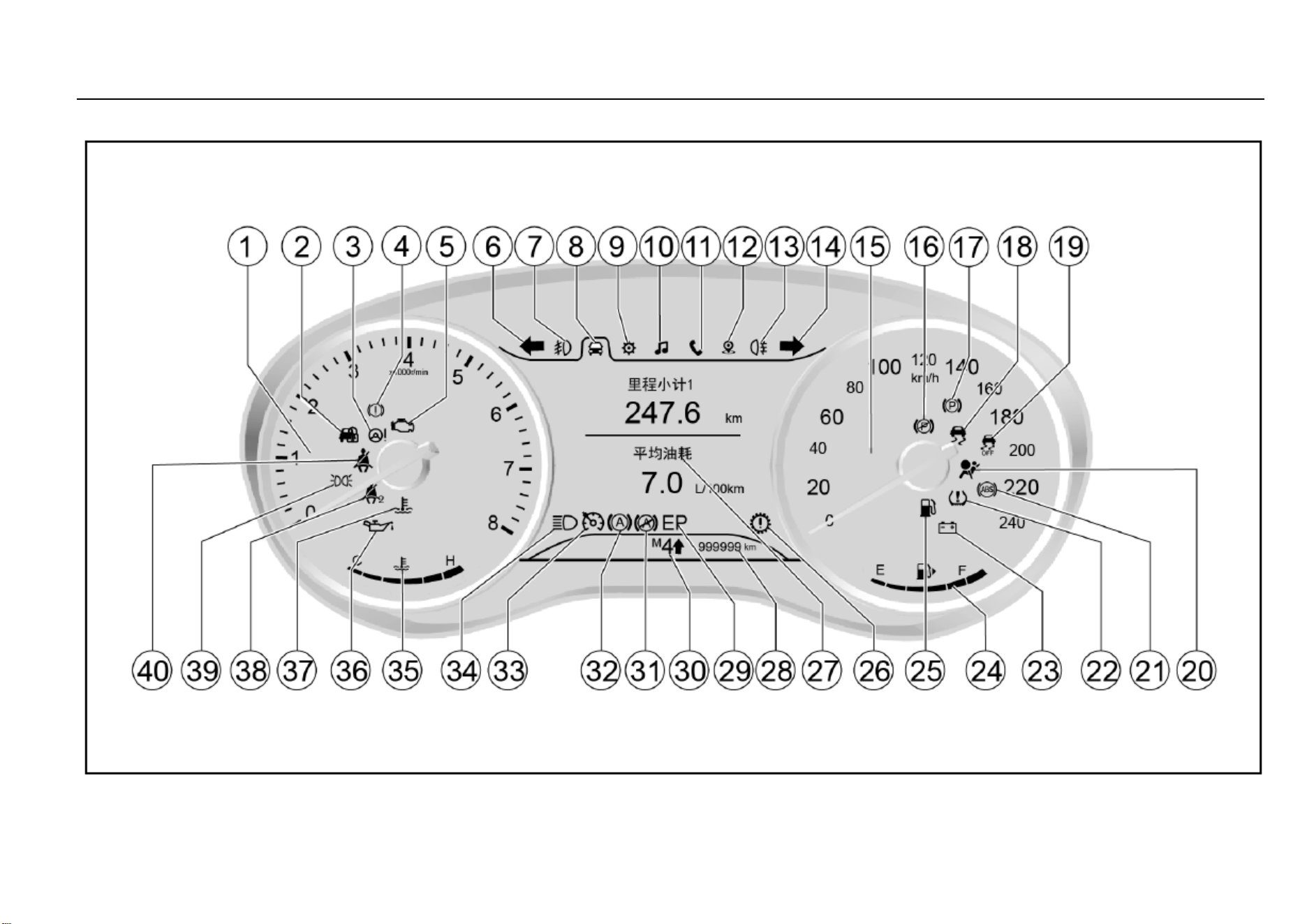
70 Instruments and Controls
Type-II Instrument Cluster
Instruments and Controls 71
4
Instruments and Controls
1. Engine tachometer
2. Engine immobilizer system indicator
3. Electronic power steering (EPS) warning lamp
4. Brake system/hand brake indicator/EBD warning lamp
5. Engine malfunction indicator
6. Left turn signal lamp/hazard warning indicator
7. Front fog lamp indicator*
8. Trip computer information option
9. Vehicle information setup option
10. Multimedia information display option
11. Bluetooth telephone information display option
12. Navigation information display option
13. Rear fog lamp indicator
14. Right turn signal lamp/hazard warning indicator
15. Speedometer:
18. Electronic stability control (ESC) fault warming lamp*
19. Electronic stability control (ESC) OFF indicator*
20. Airbag warning lamp
21. ABS warning lamp
22. Tire pressure monitor system (TPMS) fault indicator*
23. Charging system warning lamp
24. Fuel gauge
25. Fuel level low warning lamp
26. Transmission fault warning lamp*
27. Display
28. General odometer
33. Cruise control system working condition indicator*
34. Headlamp high beam indicator
35. Coolant temperature gauge
36. Engine oil pressure low warning lamp
37. Coolant temperature too high warning lamp
38. Front passenger fasten-seat-belt warning lamp
39. Position lamp indicator
40. Driver fasten-seat-belt warning lamp
After the ignition switch is turned on, as a functional test,
most of the control indicators will illuminate for a short while.
Colors of the control indicators mean:
Red = danger, important reminder
Yellow = warning, information, fault.
Green = activation confirmed.
Blue = activation confirmed.
Turn Signal Lamp/Hazard Warning Indicator
The turn signal lamp/hazard warning lamp indicator is used
to confirm whether the outside turn signal lamp/hazard
flasher can work normally. If you find that the green arrow
does not flash as you send a turning signal or press the
hazard warning button, please inspect the fuse and bulb and
if necessary, replace them.
72 Instruments and Controls
Caution
These indicators are essential for assurance of driving
safety. If the turn signal lamp or the hazard flasher
indicator bulb has burnt out, please replace it
immediately. If you fail to keep these indicators in an
agreeable working condition, accident may happen
and as a result, personal injuries, and damage to the
vehicle or other properties can occur.
Note
If the flashing time is shorter than normal, it indicates
that the turn signal lamp bulb has burnt out and must
be replaced.
Engine Oil Pressure Too Low Warning Lamp
As you turn on the ignition switch, the engine oil pressure
too low warning lamp illuminates and it goes out after the
engine gets started. This indicates that the indicator bulb
can work normally.
If this warning lamp illuminates while the engine is running,
it indicates that the engine oil pressure may have dropped
to a dangerous level. Please stop the engine and check the
oil level immediately.
If the oil level is too low, please add the specified engine oil
to the appropriate level. Please refer to the information
about engine oil level check provided in “Vehicle
Maintenance”. If the oil level is normal, please go to the
nearest Aftersales Service Center to check the lubrication
system.
Caution
When the engine oil pressure too low warning lamp
illuminates, it indicates that the engine oil pressure
may have dropped to a dangerous level. Please do not
drive the vehicle when the warning lamp has
illuminated. Otherwise, the repair charge will be
expensive.
Charging System Warning Lamp
This warning lamp illuminates as you turn on the ignition
switch. It goes out as the engine gets started. If the charging
system warning lamp illuminates during driving:
1. Drive the vehicle off the lane in a safe manner.
2. Stop the vehicle.
3. Check and confirm that the drive belt has not loosened or
broken.
4. If the drive belt is normal but the charging system warning
lamp keeps illuminated, it can indicate a charging
system fault. We advise you to go to the nearest
Aftersales Service Center for vehicle repair as soon
as possible.
Instruments and Controls 73
4
Instruments and Controls
Note
If the charging system warning lamp illuminates, it
may indicate a charging system fault.
Please do not drive the vehicle when the charging
system warning lamp has illuminated, otherwise the
vehicle can be damaged.
Note
If you often drive the vehicle for short trips, the battery
capacity consumes more quickly, so it is necessary to
replenish the electric energy by charging the battery
or having a long trip.
Coolant Temperature Too High Warning Lamp
This warning lamp illuminates as you turn on the ignition
switch and it goes out several seconds later. It indicates that
both the system and the indicator bulb can work normally.
This indicator illuminates when the coolant temperature
becomes excessively high. It indicates that the engine has
over heated. Please do not continue driving the vehicle.
Front Fog Lamp Indicator*
This indicator illuminates when the front fog lamp is turned
on. Refer to “Front Fog Lamp” in the lighting section.
Rear Fog Lamp Indicator
This indicator illuminates when the rear fog lamp is turned
on. Refer to “Rear Fog Lamp” in the lighting section.
Headlamp High Beam Indicator
74 Instruments and Controls
The high beam indicator illuminates when the headlamp
high beam is turned on.
Position Lamp Indicator
This indicator illuminates when the position lamp is turned
on.
Engine Malfunction Indicator Lamp (MIL)
This indicator lamp illuminates when the ignition switch is
turned on but the engine has not started. This indicates that
the indicator lamp bulb can work normally. The lamp goes
out after the engine is started. This malfunction indicator
lamp (MIL) illuminates upon occurrence of any component
or subsystem fault related to the emission system. Once the
electronic control module (ECM) detects any fault, the
malfunction indicator lamp will keep illuminated. In case that
serious misfire is detected, the malfunction indicator lamp
will flash constantly. Serious misfire can cause damage to
the catalytic converter. In case of this, the electronic system
of the vehicle will switch to an emergency running procedure
so that you can continue the trip. However, we advise you
to go to the nearest Aftersales Service Center for fault
removal as soon as possible. If MIL illuminates for a while
and then goes out, it is normal, not indicating any system
fault.
Caution
If MIL illuminates, it indicates a fault that must be
noted. Continuous driving after MIL has illuminated
can cause damage to the emission control system,
and reduce fuel economy and vehicle controllability.
We advise you to go to the nearest Aftersales Service
Center for vehicle repair as soon as possible.
ABS Fault Warning Lamp
The ABS warning lamp will illuminate immediately the
ignition switch is turned on. It indicates that the system is
conducting self-inspection and the warning lamp bulb can
work normally. The warning lamp goes out several seconds
later.
When the ABS warning lamp gets into the following states,
please consult the nearest Aftersales Service Center.
Not illuminated as the ignition switch is turned on
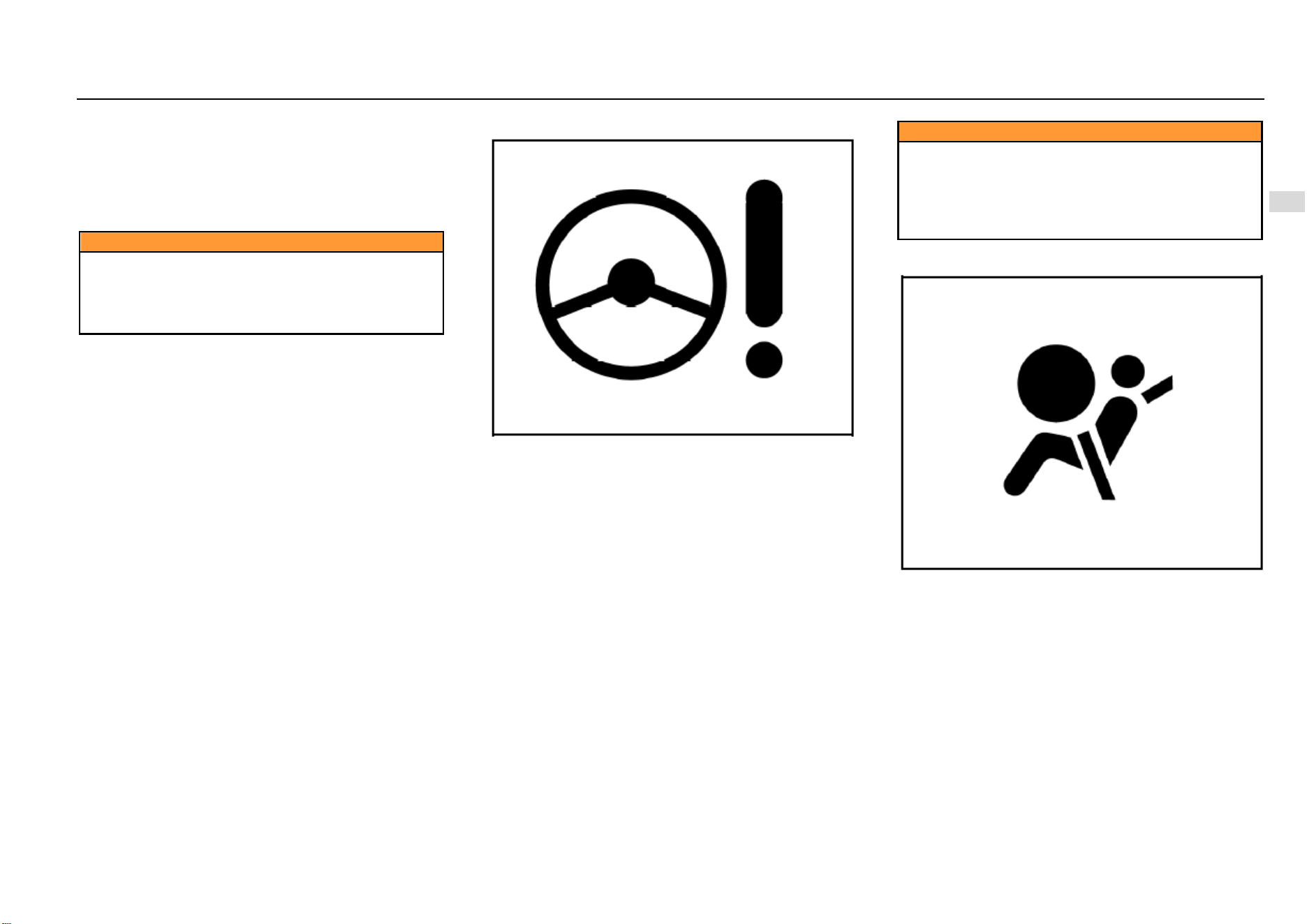
Instruments and Controls 75
4
Instruments and Controls
Always illuminated
Illuminated during driving
If the ABS warning lamp illuminates during driving, it
indicates possibility of an ABS fault. Though the vehicle can
run normally without ABS function, but we strongly advise
you to go to the nearest Aftersales Service Center for ABS
inspection and necessary repair.
Caution
Illuminated ABS warning lamp can also indicate that
the brake cannot work normally. If you fail to keep the
brake in an agreeable working condition, collision may
happen and as a result, personal injuries, and damage
to the vehicle or other properties can occur.
EPS Fault Warning Lamp
This warning lamp will illuminate immediately the ignition
switch is turned on. It indicates that the system is conducting
self-inspection and the warning lamp bulb can work
normally. The warning lamp goes out several seconds later.
When the electronic power steering (EPS) system detects a
fault, the warning lamp will give out an indication. The
vehicle can still steer even the steering system has a fault,
but it demands much greater effort. In case of the following
circumstances, please consult the nearest Aftersales
Service Center.
The lamp does not illuminate when the ignition switch
is turned on.
The lamp does not go out after it illuminates.
The lamp Illuminates during driving.
Caution
Illuminated ABS warning lamp can indicate that the
electronic power steering column cannot work
normally. If you fail to keep the steering column in an
agreeable working condition, collision may happen
and as a result, personal injuries, and damage to the
vehicle or other properties can occur.
Airbag Fault Warning Lamp
The airbag warning lamp illuminates when the ignition
switch is turned on and it goes out several seconds later.
This indicates that both the warning lamp bulb and the
airbag system can work normally.
In case of an airbag fault, the warning lamp will give out
indication in any of the following ways:
The lamp does not illuminate when the ignition switch
is turned on.
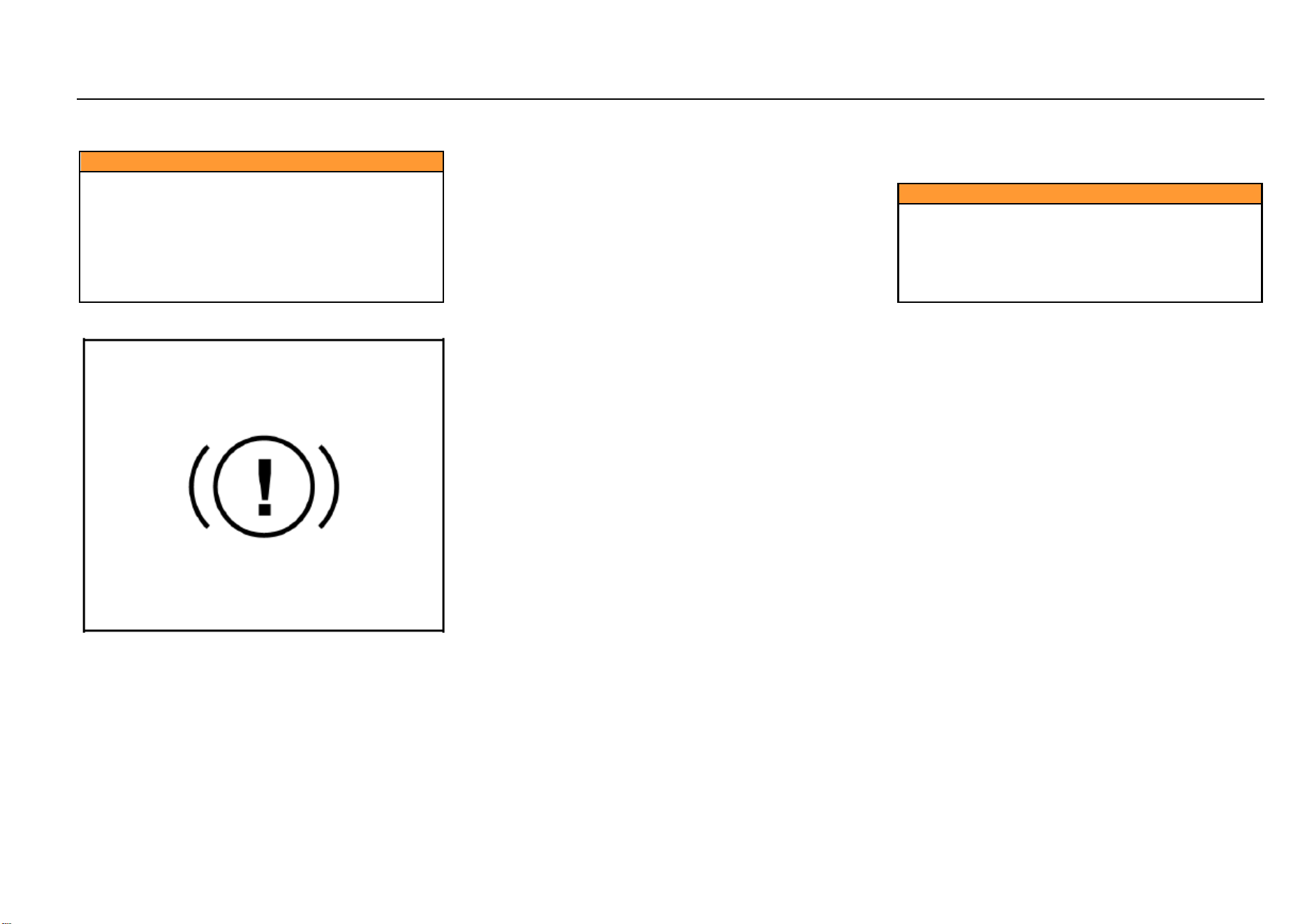
76 Instruments and Controls
The lamp does not go out after it illuminates.
Flashing or keeping illuminated during driving.
Caution
If the airbag warning lamp flashes or keeps illuminated
during driving, it indicates an airbag system fault. The
airbag system will get deactivated and thus fail to
trigger off in case of an accident. We strongly advise
you to drive the vehicle to the nearest Aftersales
Service Center for inspection. If an accident happens
after the airbag system fault has occurred, personal
injuries or even death can appear as a result.
Brake System/EBD Warning Lamp
Model with Mechanical Hand Brake
The brake system warning lamp illuminates after the ignition
switch is turned on and it goes out several seconds later (if
the parking brake has been released). This indicates that
the warning lamp can work normally.
The brake system/EBD warning lamp also illuminates when
the parking brake engages. The lamp goes out after the
parking brake is released. Please do fully release the
parking brake before starting the vehicle.
If the brake system warning lamp illuminates after the
parking brake is fully released, it indicates possibility that the
brake fluid level in the fluid reservoir is too low or an EBD
system fault has occurred.
In case of this, please operate in the following steps:
1. Carefully drive the vehicle off the lane and then stop the
vehicle.
2. Check the brake fluid level.
3. Add the recommended brake fluid until the fluid level
reaches MAX (highest) mark. Refer to “Adding
Brake/Clutch Fluid”.
4. In case of the following circumstances, we advise you to
drive the vehicle at a safe speed to the nearest
Aftersales Service Center to inspect the brake and
confirm that:
• The brake can work normally.
• You think the brake system is safe at your own
judgment.
5. In case of the following circumstances, we advise you to
tow the vehicle to the nearest Aftersales Service
Center for inspection and repair:
• You discovered brake system leakage.
• The brake system warning lamp keeps
illuminated.
• The brake cannot work normally.
Caution
Please do not drive the vehicle when the brake system
warning lamp has illuminated. This phenomenon
indicates possibility of brake failure to work normally.
Driving the vehicle after a brake fault has occurred can
lead to collision, causing personal injuries and
damage to the vehicle or other properties as a result.
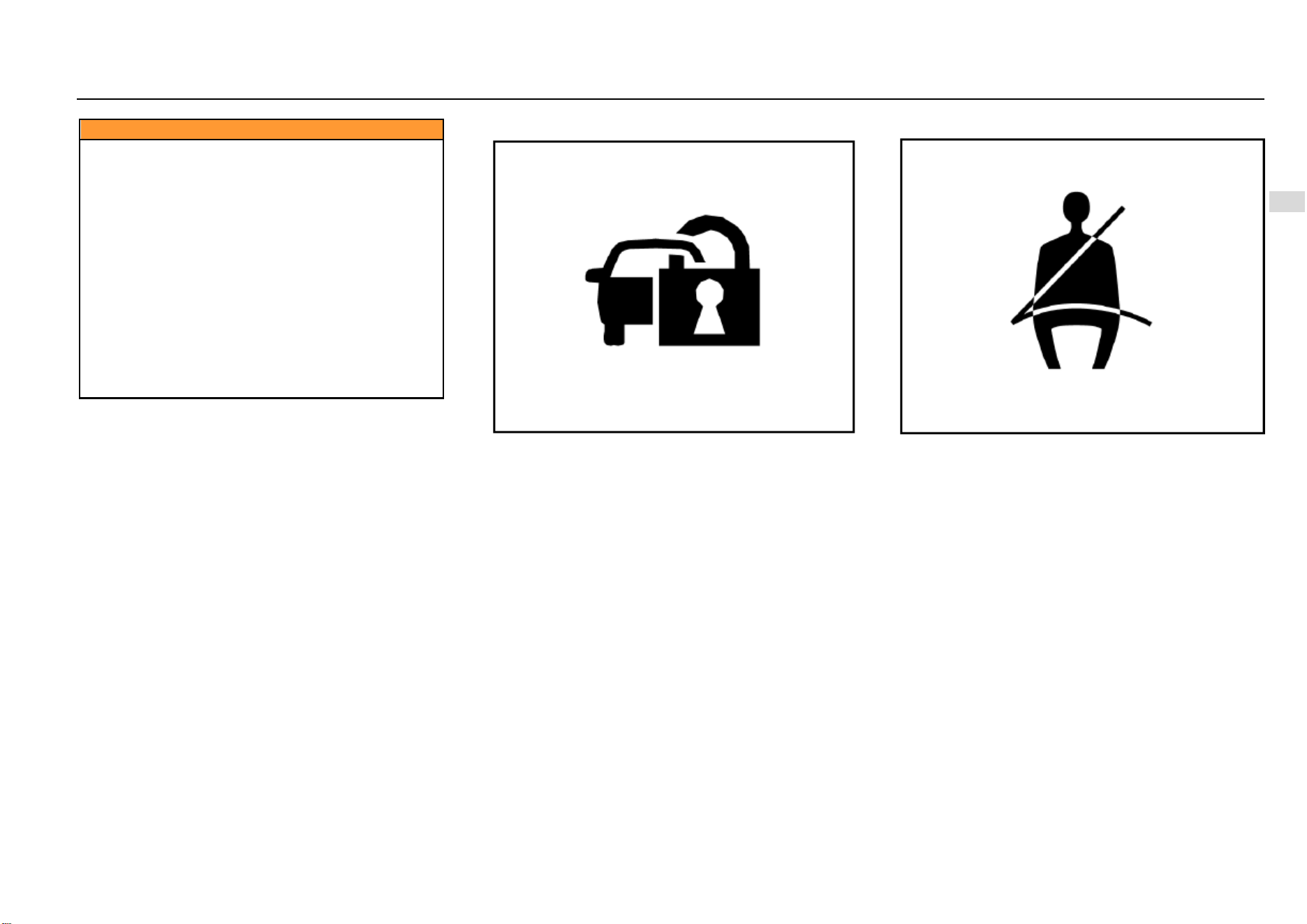
Instruments and Controls 77
4
Instruments and Controls
Caution
If the brake system warning lamp does not illuminate
after the parking brake engages with the ignition
switch turned on, please do not drive the vehicle.
Please ensure that light-emitting diode of the warning
lamp works normally. If the lamp does not illuminate
when the parking brake engages with the ignition
switch turned on, even though light-emitting diode of
the warning lamp works normally, we still advise you
to go to the nearest Aftersales Service Center to
inspect the brake system.
These phenomena indicate possibility of a brake
system fault.
If you fail to keep the brake in an agreeable working
condition, collision may happen and as a result,
personal injuries, and damage to the vehicle or other
properties can occur.
Engine Immobilizer System Indicator
This indicator illuminates when the door is opened. It goes
out after the engine is started. This indicates that the
indicator can work normally. Refer to information on engine
immobilizer system given in “Driving and Controls”.
Driver Fasten-Seat-Belt Warning Lamp
The seat belt warning lamp illuminates if the driver does not
fasten the seat belt properly after the ignition switch is
turned on. Following this, the following circumstances will
appear unless the driver fastens the seat belt properly:
The seat belt warning lamp keeps illuminated;
If the vehicle speed exceeds 20 km/h, the warning
lamp will flash and the warning buzzer will buzz for a
certain time.
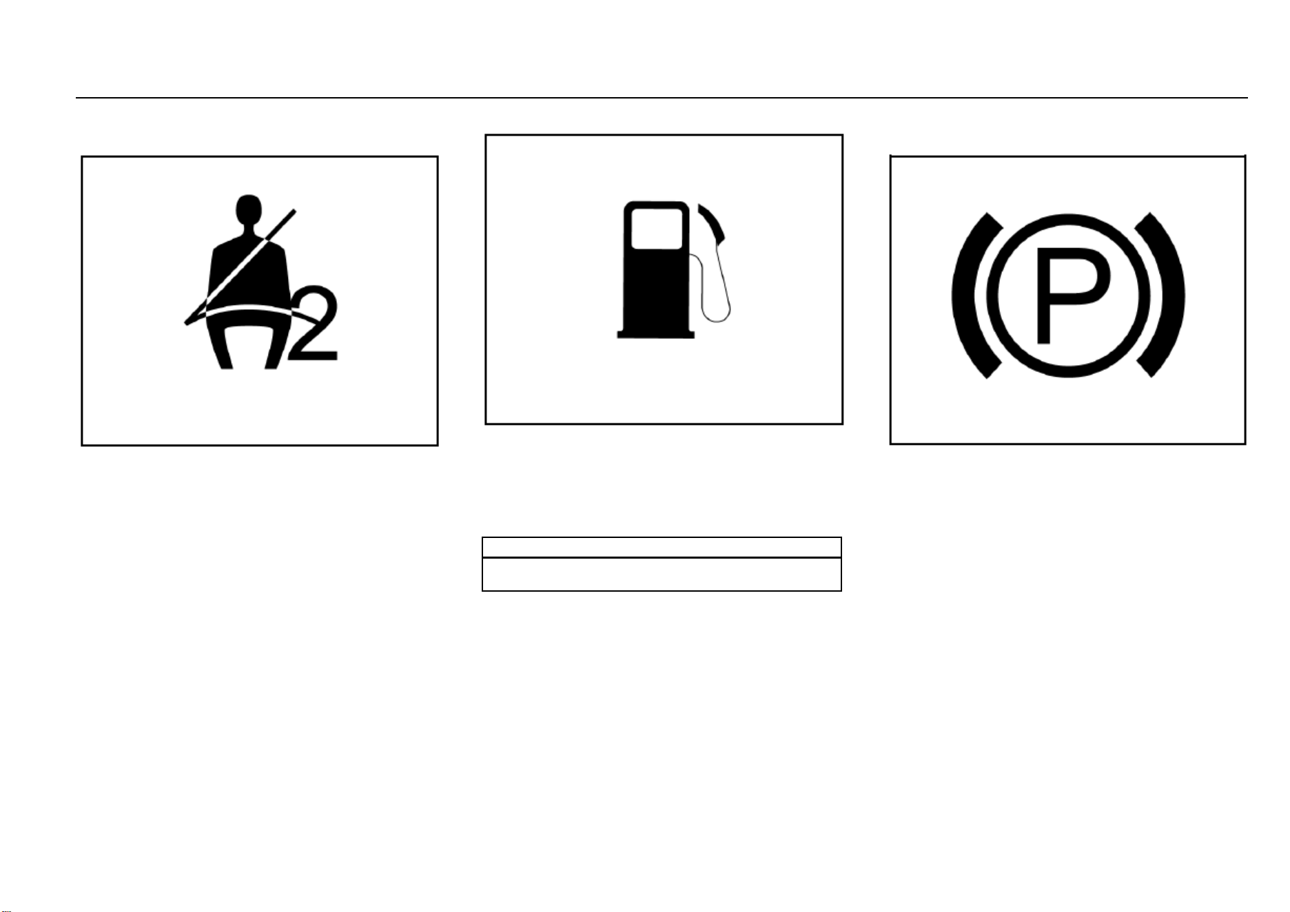
78 Instruments and Controls
Front Passenger Fasten-Seat-Belt Warning
Lamp*
The seat belt warning lamp illuminates if the front passenger
seat is occupied but the occupant does not fasten the seat
belt properly after the ignition switch is turned on. Following
this, the following circumstances will appear unless the front
passenger fastens the seat belt properly:
The seat belt warning lamp keeps illuminated;
If the vehicle speed exceeds 20 km/h, the warning
lamp will flash and the warning buzzer will buzz for a
certain time.
This warning lamp does not illuminate if the front passenger
seat is not occupied after the ignition switch is turned on.
Fuel Level Too Low Warning Lamp
This warning lamp will illuminate immediately the ignition
switch is turned on. It indicates that the system is conducting
self-inspection and the warning lamp bulb can work
normally. If this lamp keeps illuminated after the ignition
switch is turned on or it illuminates during driving, it indicates
that the fuel amount in the fuel tank is insufficient and you
should replenish the fuel in time.
Note
Do not exhaust the fuel, otherwise the catalytic
converter can be damaged.
Electronic Parking Brake (EPB) Working
Indicator*
The electronic parking brake (EPB) working indicator
illuminates as the electronic parking brake is pulled up. This
indicates that the vehicle is in a parking state.
This indicator goes out as the electronic parking brake is
released. This indicates that the vehicle is out of the parking
state.
This indicator keeps illuminated as long as the electronic
parking brake engages firmly.
For details about the electronic parking brake (EPB), please
refer to “Parking Brake” under “Driving and Controls”.

Instruments and Controls 79
4
Instruments and Controls
Electronic Parking Brake (EPB) Fault Warning
Lamp*
The electronic parking brake fault warning lamp illuminates
after the ignition switch is turned on and it goes out several
seconds later. This indicates that both the warning lamp and
the electronic parking brake function module can work
normally.
In case of an electronic parking brake fault or a warning
lamp fault, it will be indicated in any of the following ways:
The lamp does not illuminate when the ignition switch
is turned on.
The lamp does not go out after it illuminates.
The lamp Illuminates during driving.
Once the electronic parking brake (EPB) fault warning lamp
shows the above abnormalities, please contact the Service
Center in time. An electronic parking brake fault can cause
the vehicle to coast.
80 Instruments and Controls
ESC Fault Warning Lamp
The warning lamp illuminates after the ignition switch is
turned on and it goes out several seconds later. This
indicates that the warning lamp can work normally. The ESC
lamp flashes once the ESC function is triggered off. The
system informs the driver that ESC is working in this way. If
the ESC lamp keeps illuminated, it indicates an ESC fault.
Please refer to information given in “Electronic Stability
Control (ESC)” under “Driving and Controls”.
ESC OFF Indicator
The warning lamp illuminates after the ignition switch is
turned on and it goes out several seconds later. This
indicates that the warning lamp can work normally. If you
press “ESC OFF” switch when the vehicle speed has not
exceeded the threshold value, certain functions of ESC will
be deactivated. At this time, ESC OFF indicator illuminates.
Please refer to information given in “Electronic Stability
Control (ESC)” under “Driving and Controls”.
Note
Generally, it is not advised to turn ESC OFF switch off.
Transmission Fault Warning Lamp*
The transmission fault warning lamp illuminates when the
ignition switch is turned on and it goes out several seconds
later. This indicates that both the warning lamp bulb control
system can work normally.
For certain vehicle models, the warning lamp does not
illuminate when the ignition switch is turned on. It only
illuminates upon fault occurrence.
Instruments and Controls 81
4
Instruments and Controls
Cruise Control System Working Condition
Indicator*
This indicator illuminates when the cruise control function is
activated. Refer to information given in “Cruise Control
System” under “Driving and Controls”.
TPMS Fault Indicator*
The warning lamp illuminates after the ignition switch is
turned on and it goes out several seconds later. This
indicates that the warning lamp can work normally.
The TPMS fault indicator illuminates when the tire pressure
is too low or too high, or when a TPMS fault occurs.
For the correct tire pressures, please refer to “Technical
Data”.
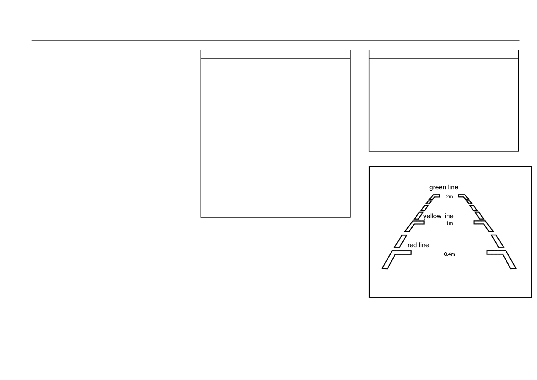
82 Instruments and Controls
Reverse Sensor*
The intelligent reverse sensor judges the distance between
rear end of the vehicle and the obstacle via the ultrasonic
transducer installed on the rear bumper.
If the buzzer buzzes once after you turn on the ignition
switch and shift to reverse gear, it indicates that the system
can work normally.
If the buzzer buzzes twice, it indicates that one transducer
fails to work; if it buzzes thrice, it indicates that 2 or more
transducers cannot work normally.
The intelligent reverse sensor starts to work immediately
every time you turn on the ignition switch and shift to reverse
gear.
When the distance between the vehicle and the obstacle
behind it is within about 1.5 m~1.0 m, the reverse buzzer
sends out alarm sound at long intervals.
When the distance between the vehicle and the obstacle
behind it is within about 1.0 m~0.6 m, the reverse buzzer
sends out alarm sound at short intervals.
When the distance between the vehicle and the obstacle
behind it is within about 0.6 m~0.4 m, the reverse buzzer
sends out alarm sound at shorter intervals.
When the distance between the vehicle and the obstacle
behind it is within about 0.4 m, the reverse buzzer sends out
alarm sound constantly.
Note
● To ensure reversing safety and to leave enough time
for the system to detect, please drive at a speed of 5
km/h or lower during reversing.
● Please stop the vehicle immediately a constant
alarm sound is heard in case that the vehicle bumps
onto the obstacle behind it.
● Please do not knock the transducers hard or wash
them directly with a high-pressure water gun,
otherwise the transducers can be damaged.
● Sundries on the transducers such as snow, mud and
water drops can lead to misoperation.
● Please note that the system is likely to fail to detect
the following obstacles: those of a conical shape or
acute angle reflectors; objects which are prone to
absorb sound wave, such as cotton and snow; fine
objects such as iron gauze and ropes; objects 30 cm
or lower to the ground or 1 m or higher than the
ground. The system may detect these obstacles first,
but as they become nearer and nearer to the vehicle,
they can get out of the effective detection range, not
detected as a result.
● When reversing down or up a slope, the system may
give out a wrong warning, reminding you to take great
care.
Note
● Please note that the system is likely to work
abnormally due to wrong induction under the
following circumstances: reversing the vehicle on an
uneven road, a road paved with round stones, an
uphill road or grassland; interference from ultrasonic
noise, metallic sound or high-pressure gas emission
sound of the same frequency; sundries on the
transducers; height change of vehicle rear end under
heavy load; other detecting equipment installed within
the effective detection range.
● If any nonstandard radio communication equipment
is installed on the vehicle, usage of such equipment
(not including mobile cellphone and audio system)
may affect the function of this system.
Reverse Video Display*
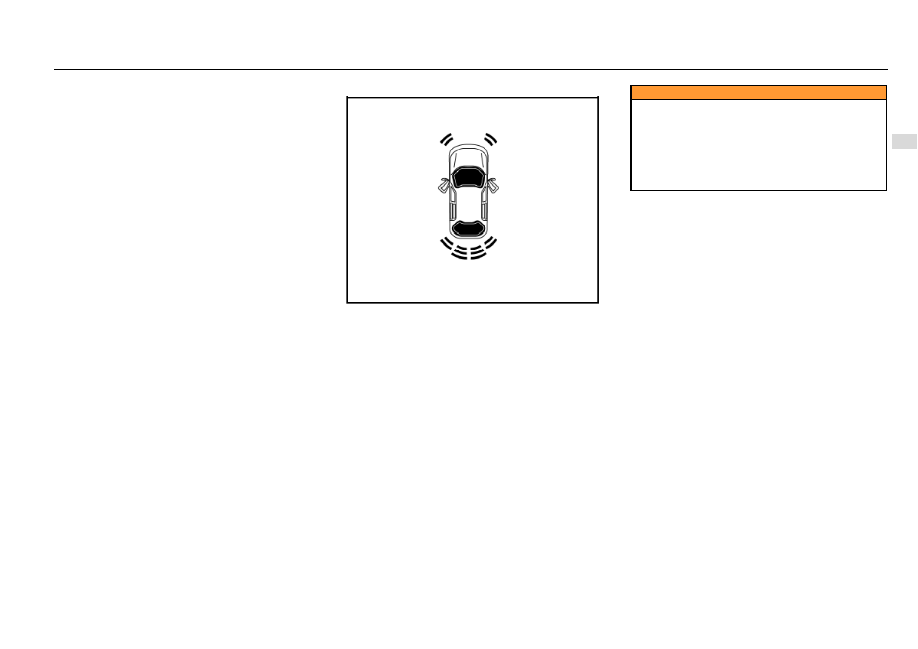
Instruments and Controls 83
4
Instruments and Controls
As is shown in the figure, if the vehicle is equipped with
reverse camera, images behind the vehicle, reverse
auxiliary lines and guide lines will appear on the multimedia
player screen after you turn on the ignition switch, release
the parking brake and shift to reverse gear “R”. If the vehicle
is of high configuration, a sector indication area will also
show on the screen.
Reverse Auxiliary Line
The auxiliary is divided into three sections: red, yellow and
green, based on the distance between the object and rear
end of the vehicle.
The bottom red line represents the warning line for a
distance front the obstacle to the vehicle rear end within 0.4
m; the middle yellow line represents the warning line for a
distance from the obstacle to the vehicle rear end within 1.0
m; the top green line represents the warning line for a
distance the obstacle to the vehicle rear end within 2.0 m;
the line on both sides is the vehicle width indication line.
Reverse Guide Line*
The yellow guide line can develop into a dynamic virtual
guiding line as you turn the steering wheel.
Sector Indication Area*
As is shown in the figure, a total of 6 sector indication areas
are shown on the screen, indicating the distance from the
obstacle to front left, front right, rear left, rear right, rear left
middle and rear right middle of the vehicle respectively.
For the front left, front right, rear left and rear right sector
indication areas:
When the distance from the vehicle to the obstacle is within
about 0.4 m~0.6 m, the sector indication area appears
yellow and the buzzer sends out alarm sound at short
intervals. When the distance is within 0.4 m, the sector
indication area appears red and the buzzer sends out alarm
sound constantly.
For the rear left middle and rear right middle sector
indication areas: When the distance from the vehicle to the
obstacle is within about 0.6 m~1.0 m, the sector indication
area appears green and the buzzer sends out alarm sound
intermittently. When the distance is within 0.4 m~0.6 m, the
sector indication area appears yellow and the buzzer sends
out alarm sound at short intervals. When the distance is
within 0.4 m, the sector indication area appears red and the
buzzer sends out alarm sound constantly.
Caution
The intelligent reverse camera can only help the driver
avoid accident during reversing. The driver should
always keep concentrated. SGMW shoulders no
responsibility for any personal injury or vehicle
damage resulting from careless driving with great
reliance on the on-board reverse camera. Before
reversing, please ensure that no child or animal is near
the vehicle.
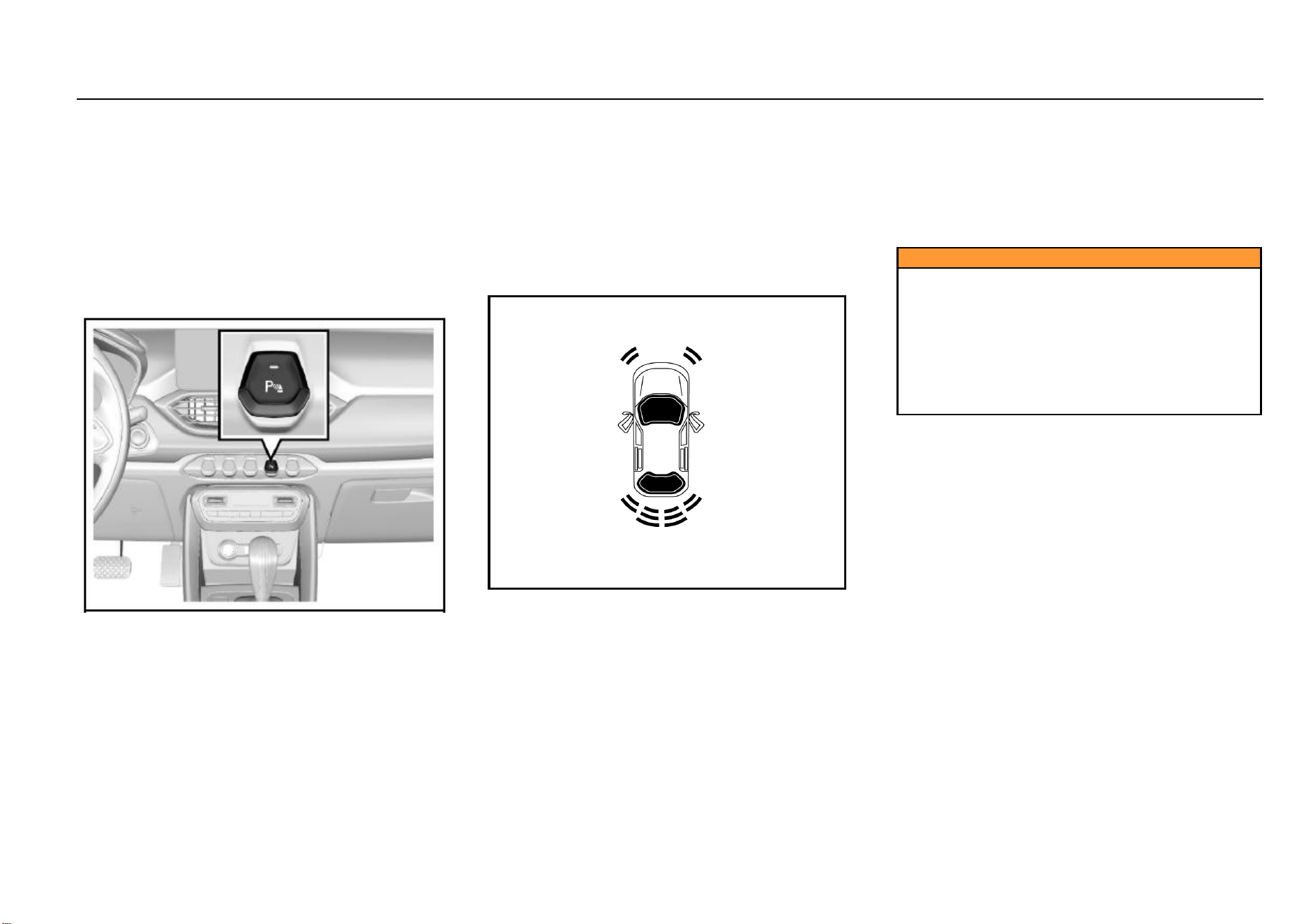
84 Instruments and Controls
Parking Assist System*
The parking assist system judges the distance between
front/rear end of the vehicle and the obstacle via the
ultrasonic transducer installed on the front/rear bumper. If
the buzzer buzzes once after you turn on the ignition switch,
it indicates that the system can work normally.
If the buzzer buzzes twice, it indicates that one transducer
fails to work; if it buzzes thrice, it indicates that 2 or more
transducers cannot work normally.
When a transducer fault is detected, the fault information will
appear on the audio system display screen.
Parking Assist System Switch*
If the vehicle is equipped with parking assist system switch,
the switch indicator will illuminate after the ignition switch is
turned on and the parking assist system switch is pressed;
if the parking brake is released at this time, the parking
assist system starts to work.
If front/rear end of the vehicle is within certain distance from
the obstacle, parking assist indication will appear on the
audio system display screen. Press the switch again and the
parking assist system turns off. The switch indicator also
goes out.
The parking assist system activates automatically (under
the precondition that the parking brake is released) as the
shift lever is turned to the reverse gear.
It exits when the vehicle speed exceeds 15 km/h. To
activate the system again, please press the switch.
Parking System Display*
As is shown in the figure, when the transmission is engaged
on the forward or the neutral gear, a prompt window will pop
up in the audio system display screen as front end of the
vehicle is within about 0.6 m from the obstacle or rear end
of the vehicle is within about 1.5 m from the obstacle.
Color of the front and rear sector areas will change as the
distance changes, accompanied by alarm sound. Please
refer to information given in “Sector Indication Area”.
The prompt window will disappear when the system detects
no obstacle.
The window will disappear immediately you press the
window off button (×). It will appear again if an obstacle is
detected.
Caution
The reverse camera and the parking assist system can
only help the driver avoid accident during reversing or
parking. The driver should always keep concentrated.
SGMW shoulders no responsibility for any personal
injury or vehicle damage resulting from careless
driving with great reliance on the on-board radar
system. Before reversing or parking, please ensure
that no child or animal is near the vehicle as the radar
system may fail to respond to them.

Lighting 85
5
Lighting
Lighting
Outside Lighting .............................................................. 86
Lighting Switches ................................................... 86
High Beam ............................................................. 86
Headlamp Flashing ................................................ 86
Hazard Flasher ...................................................... 86
Turn and Lane Change Signal Lamp ..................... 87
Front Fog Lamp* .................................................... 87
Rear Fog Lamp ...................................................... 88
Backup Lamp ......................................................... 88
Stop Lamp ............................................................. 88
Day Running Lamp* ............................................... 88
Headlamp Leveling ................................................ 88
Headlamp OFF Delay ............................................ 88
Lamp ON Reminder ............................................... 88
Inside Lighting ................................................................. 89
Front Reading Lamp .............................................. 89
Rear Reading Lamp ............................................... 90
Luggage Compartment Illumination Lamp ............. 90
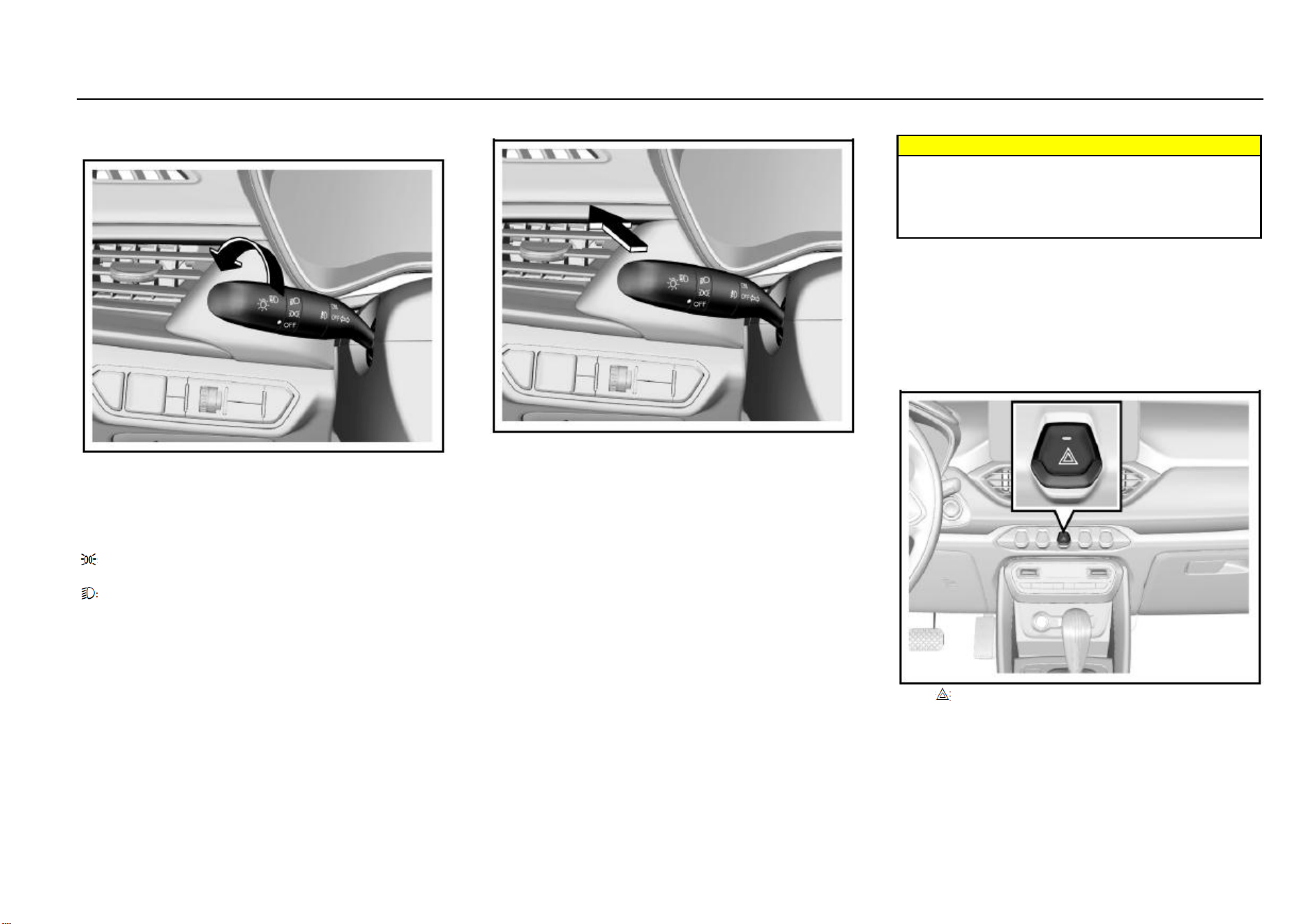
86 Lighting
Outside Lighting
Lighting Switches
To switch on or off the headlamp, tail lamp and parking
lamp, please turn the end of the combination switch control
lever.
The lighting switch has 3 positions and they represent
different lighting functions:
OFF= All the lamps are turned off.
= The position lamp, license plate lamp, instrument panel
lamp and backlight of all the panels illuminate.
= The low beam lamp and all lamps mentioned above
illuminate under the precondition that the ignition switch is
turned to ON position.
High Beam
To turn on headlamp high beam:
Ensure that the ignition switch is in ON position;
The headlamp is in a low beam state;
As is shown in the figure, push the combination switch
control lever towards the instrument panel.
The headlamp high beam indicator illuminates when the
headlamp high beam is turned on. To switch from headlamp
high beam to low beam, pull the control lever towards the
opposite direction until it returns to the normal position.
Warning
When approaching the on-coming vehicle or the
vehicle ahead, please do switch the high beam to low
beam. This is because headlamp high beam can make
other drivers feel temporarily blind and cause collision
as a result.
Headlamp Flashing
To activate headlamp high beam flashing, please pull the
combination switch control lever toward yourself and then
release it. The control lever will return to the normal position
as you release it.
Before you release the control lever, the headlamp high
beam keeps illuminated.
Hazard Flasher
Press to turn on/off the hazard flasher.
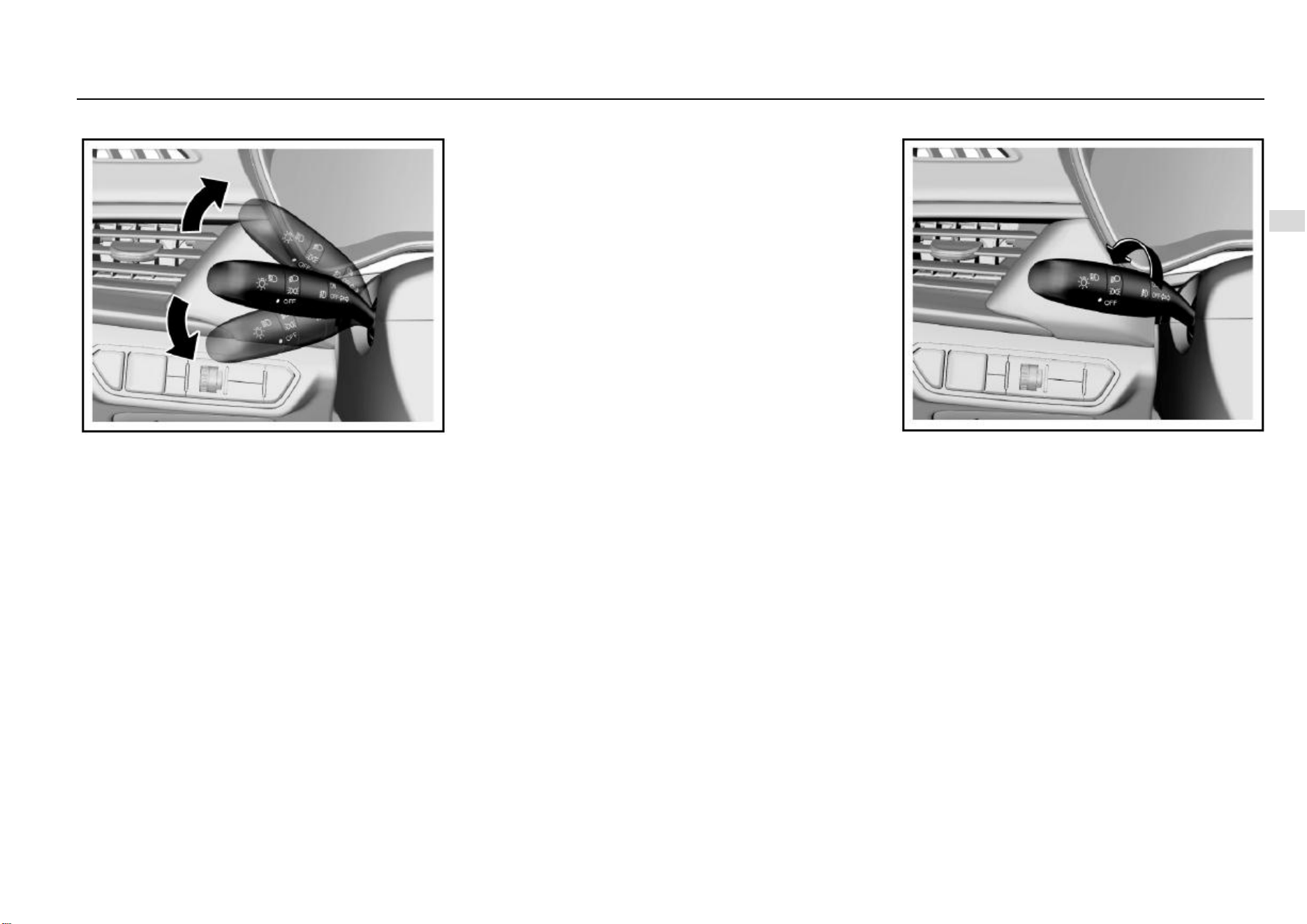
Lighting 87
5
Lighting
Turn and Lane Change Signal Lamp
To turn on the turn and lane change signal lamp, the ignition
switch must be in ON position.
Control lever upward = right turn signal lamp
Control lever downward = left turn signal lamp
After cornering, the turn signal interrupts automatically and
the control lever returns to the normal position.
To change the lane, you can pull the control lever to halfway
position (not reaching the turn signal lamp position) and
keep pulling it. After lane change, release the control lever
and it will return to the normal position automatically.
A rear turn signal lamp is integrated on the rear combination
lamp and the rear bumper of your vehicle respectively. If you
turn on the turn signal lamp with the liftgate open, the turn
signal lamp on the rear bumper will illuminate. This ensures
that a turn signal is sent to the drivers behind even when the
liftgate is open.
Steering Assist Lighting Function*
During steering, the two front fog lamp will illuminate to
provide auxiliary lighting if certain conditions are satisfied.
These conditions are:
1. The engine is running;
2. The vehicle speed is ≤ 35 Km/h;
3. The low beam lamp is turned on;
4. The steering wheel angle is >60° or the turn signal lamp
switch is turned on.
As the front fog lamp illuminates, the front fog lamp indicator
on the instrument panel also illuminates.
The steering assist lighting function deactivates and the
front fog lamps go out after a while under any of the
following condition:
1. The steering wheel angle is ≤ 30° or the turn signal lamp
switch is turned off.
2. The ignition switch is turned to a position other than ON.
3. The vehicle speed is > 40 Km/h;
4. The low beam lamp is turned off.
Front Fog Lamp*
When the ignition switch is turned to ON position, and the
headlamp functions as a position lamp or in a low beam
state, turn the ring button in the middle of the combination
switch to ON (connected) position to turn on the front fog
lamp. Turn the ring switch to OFF (disconnected) position to
turn off the front fog lamp.
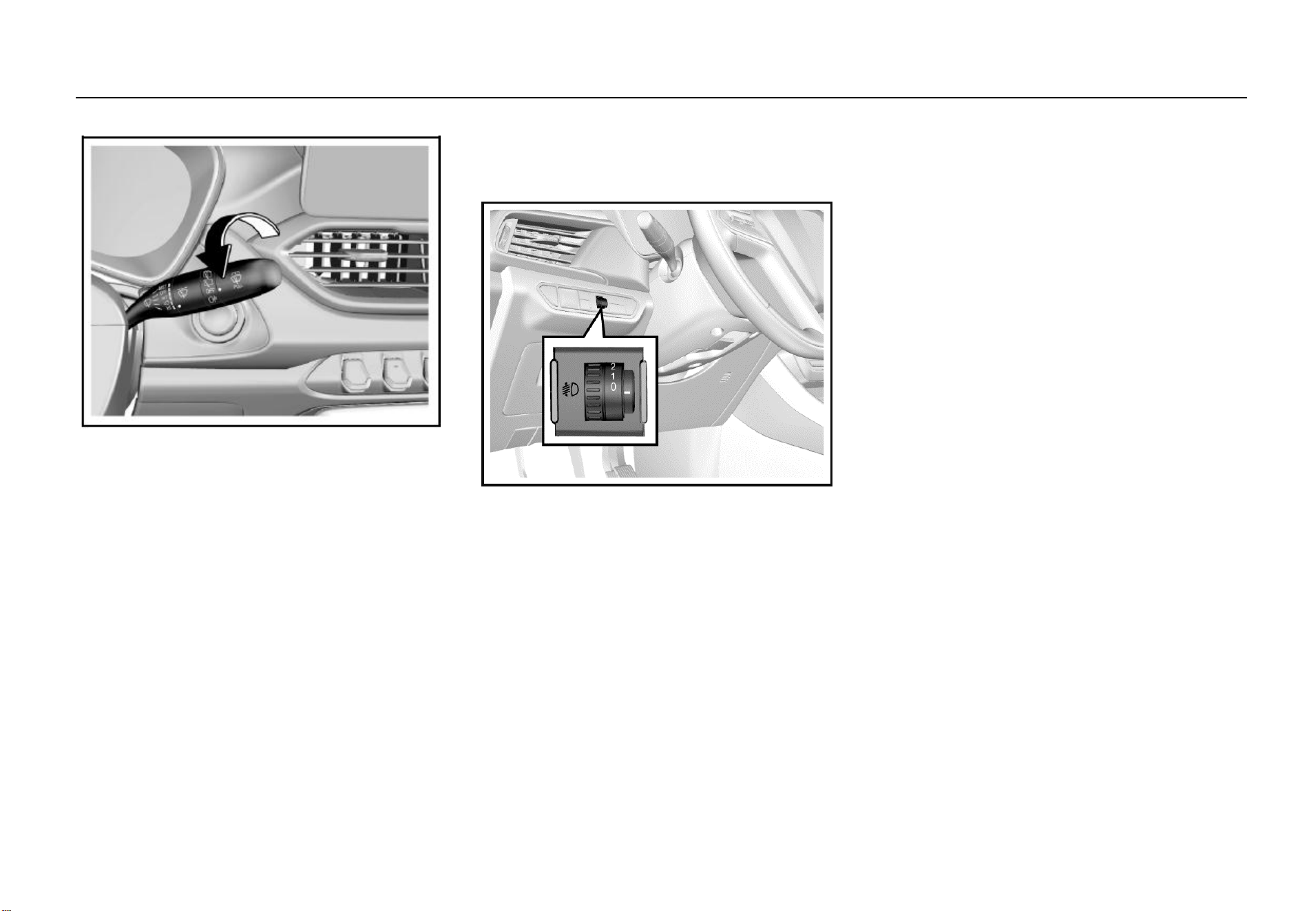
88 Lighting
Rear Fog Lamp
When the headlamp is in low beam state or the front fog
lamp is turned on, turn the rear wiper control knob to “s”
position and then release it to turn on the rear fog lamp. Turn
the knob again to turn off the rear fog lamp.
If the low beam lamp or front fog lamp is turned off with the
rear fog lamp turned on, the rear fog lamp keeps on.
Backup Lamp
The backup lamp illuminates after you turn on the ignition
switch and shift to reverse gear.
Stop Lamp
The stop lamp illuminates as you depress the brake pedal.
Day Running Lamp*
The day running lamp turns on automatically as the engine
starts; it goes out automatically as the position lamp is
turned on.
Headlamp Leveling
The headlamp leveling knob is located at the left side of the
instrument panel.
Please adapt the headlamp illuminate range to the vehicle
load so as to acquire the best lighting effect and avoid
dazzling. Turn the knob to the desired position:
0 = front seats occupied
1 = all seats occupied
2 = all seats occupied with the luggage compartment loaded
3 = driver’s seat occupied with the luggage compartment
loaded
Headlamp OFF Delay
To trigger off headlamp OFF delay function, turn off the
headlamp and pull the light control lever towards the
steering wheel within one second for twice after you shut
down the engine and turn the ignition switch to ACC or
LOCK position, or after you pull out the key. After remote
locking, the low beam lamp will turn off automatically 30s
later; if the vehicle is not remotely locked, the low beam
lamp will turn off automatically 10 minutes later.
Lamp ON Reminder
If any lamp switch is not turned to OFF position after you
turn the ignition switch to LOCK position or pull out the key,
the buzzer will send out alarm sound as the driver’s door is
opened. The alarm sound stops after the lamp is turned off.
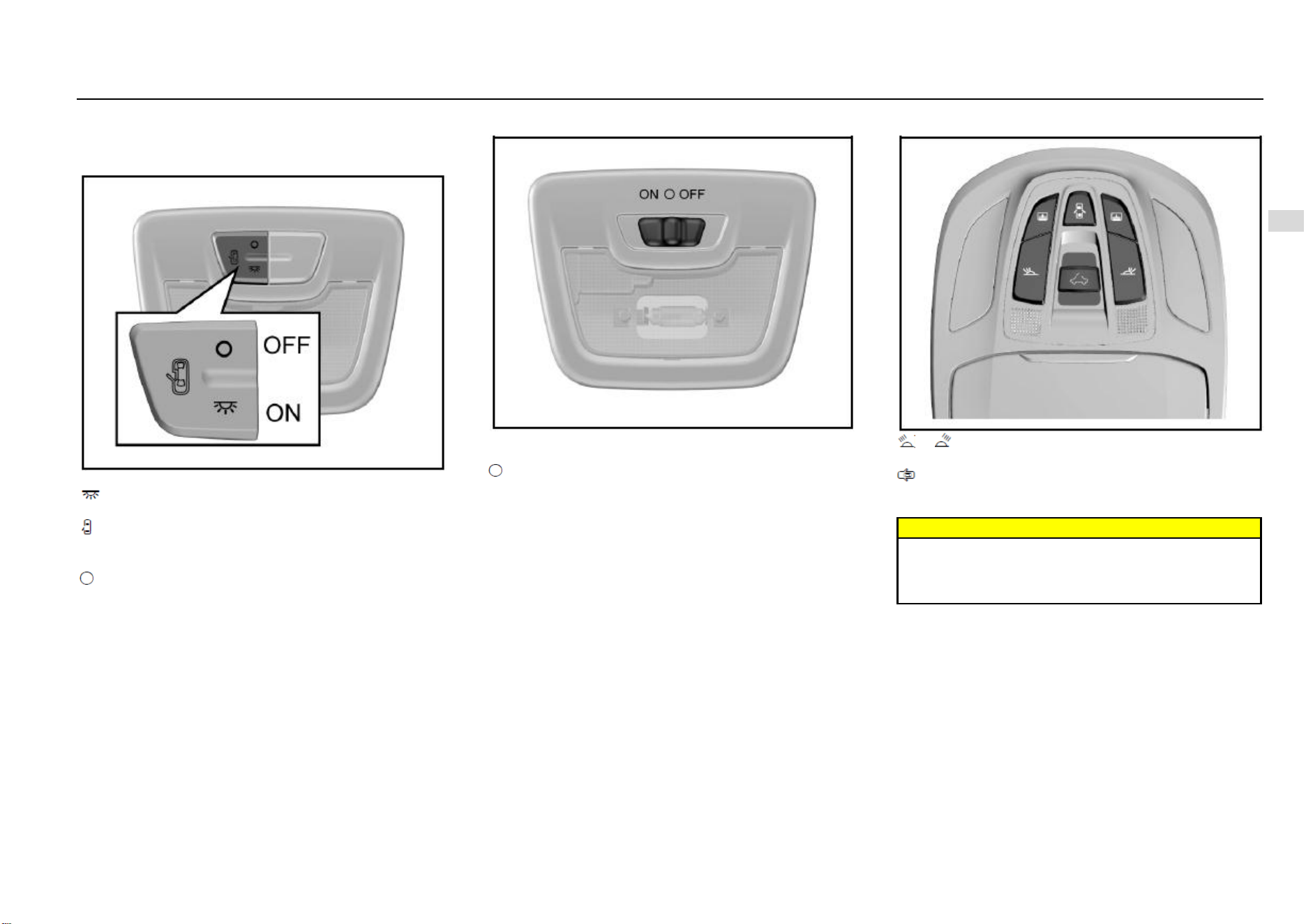
Lighting 89
5
Lighting
Inside Lighting
Front Reading Lamp
Type-I
The lamp has 3 working positions.
: The lamp illuminates and keeps illuminated until it is
manually turned off.
: The lamp gradually illuminates as any door is opened; it
works for a while and then gradually goes out after all the
doors (including liftgate) are closed.
: The lamp does not illuminate even a door is opened.
Type-II
ON: The lamp illuminates and keeps illuminated until it is
manually turned off.
(Intermediate position): The lamp illuminates as the door
(including the liftgate) is opened; it gradually goes out after
all the doors are closed.
OFF: The lamp does not illuminate even a door is opened.
Type-III
or : Press the button to turn on the left/right reading
lamp and press it again to turn the lamp off.
: The reading lamp gradually illuminates if any door is
opened (including liftgate) as the button is pressed. It
gradually goes out after all the doors are closed.
Warning
Please avoid usage of the inside lamps during driving
in darkness. A bright passenger compartment can
reduce the visibility outside and cause collision as a
result.
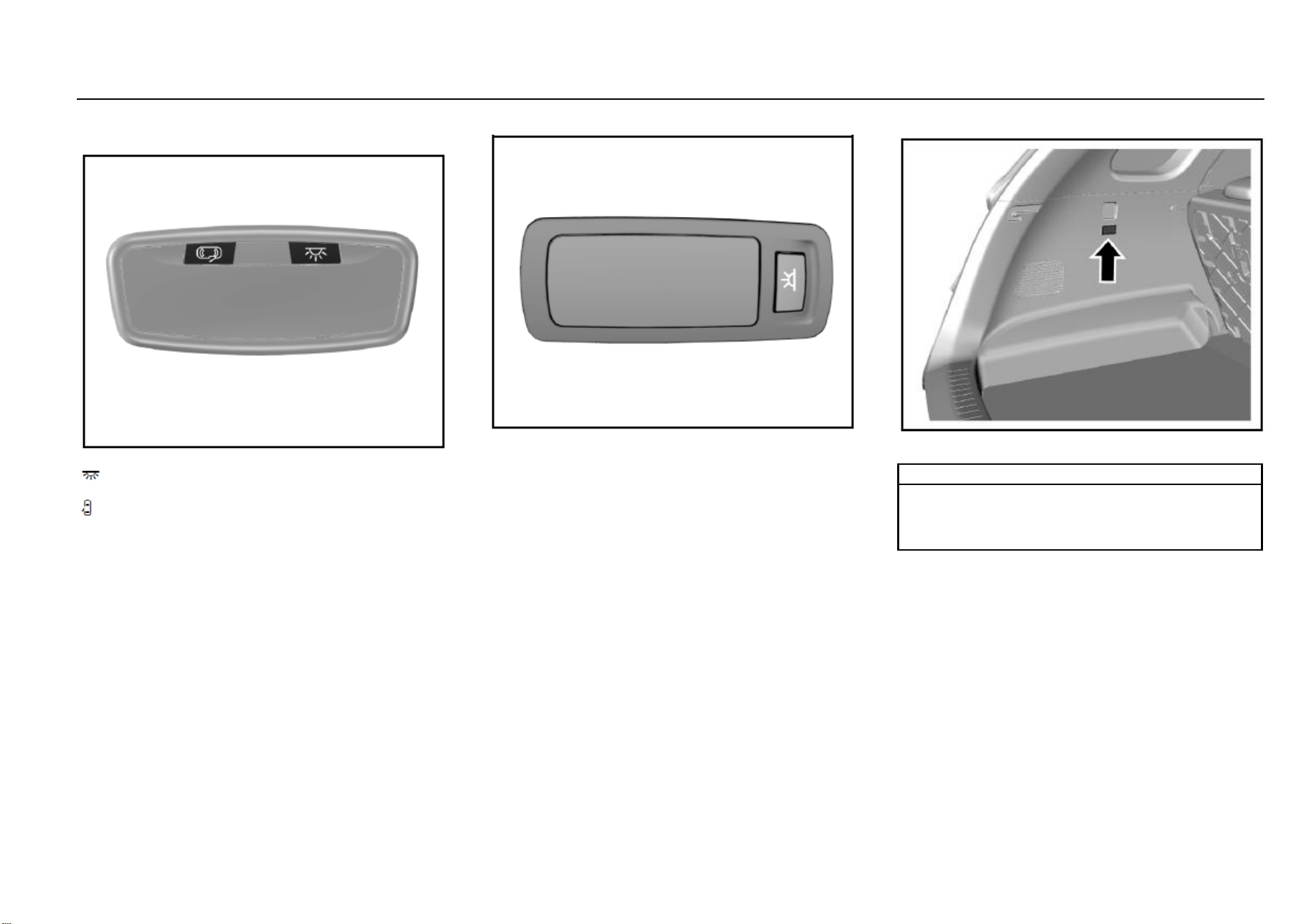
90 Lighting
Rear Reading Lamp
Type-I
The rear reading lamp has 2 working buttons:
: Press the switch and the lamp illuminates. It will not go
out until the switch is pressed again.
: The lamp gradually illuminates if the switch is pressed
and any door is opened; it works for a while and then
gradually goes out after all the doors (including liftgate) are
closed.
Type-II
For certain models, two reading lamps are installed on the
roof over the second row seats. You can press the reading
lamp switch to turn it on/off.
Luggage Compartment Illumination Lamp
The luggage compartment illumination lamp illuminates as
the liftgate is opened. It goes out after the liftgate is closed.
Note
Please do not replace with a high-power bulb (for
example, refit with a xenon headlamp) in case that the
lamp burns out or an accident arises from it.
Please turn off all lamps before you leave the vehicle.

Audio Entertainment System 91
6
Audio Entertainment System
Driver Information and
Entertainment
Audio Control Buttons on Steering Wheel* ...................... 92
Driver Information and Entertainment .............................. 93
Navigator Upgrading* ...................................................... 94
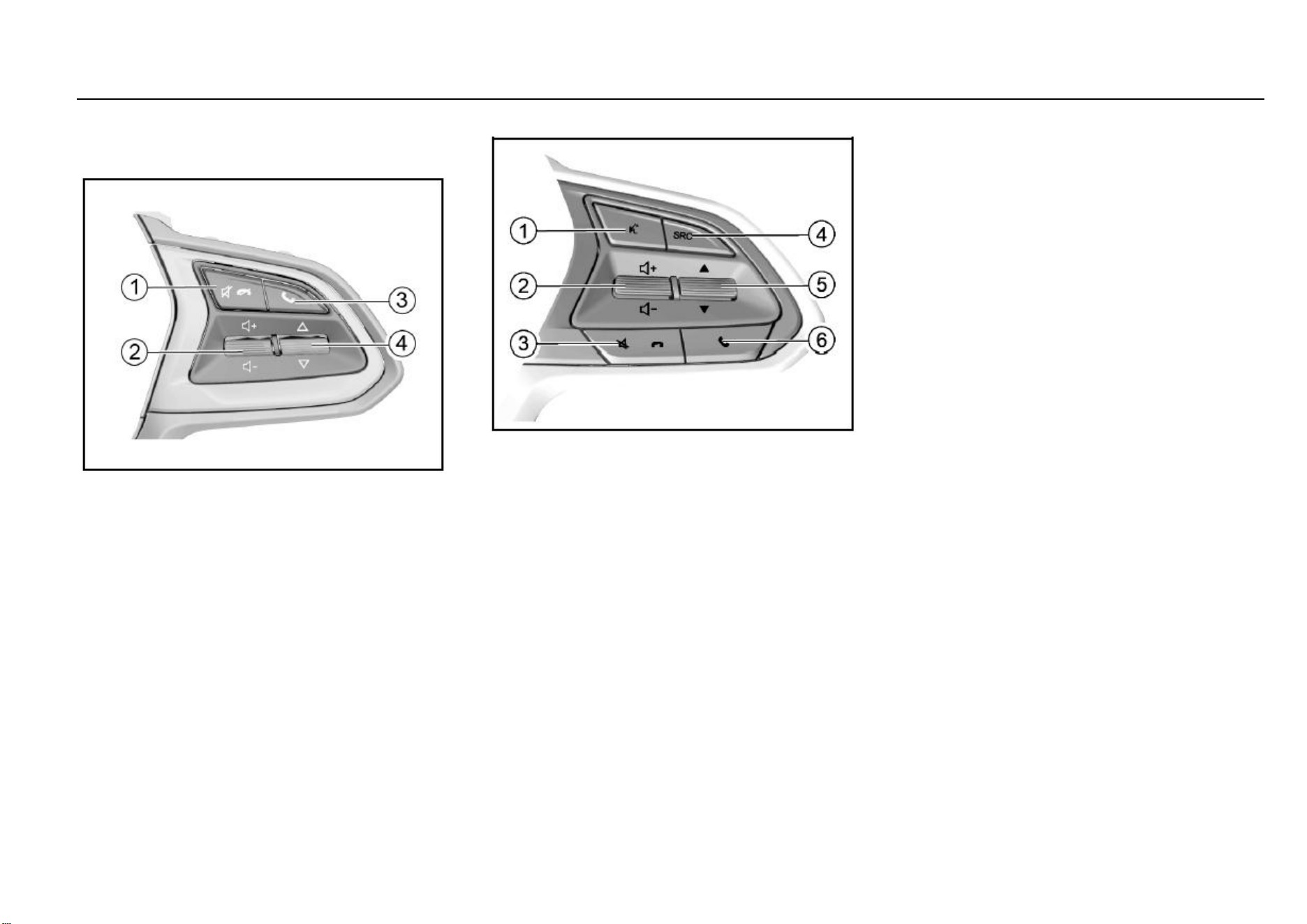
92 Audio Entertainment System
Audio Control Buttons on Steering
Wheel*
Type-I
1. Mute or Call Hangup Button
It is used to sound off or hang up a Bluetooth telephone call.
2. Volume Adjustment Thumbwheel
Pull the thumbwheel up and down to adjust the sound
volume.
3. Bluetooth Setup or Call Answer Button
Press the button to enter the Bluetooth interface or answer
the Bluetooth telephone call.
4. Song Selection/Station Switch Thumbwheel
Pull the thumbwheel up and down to select the station or
song.
Type-II
1. Reserved Button
It is reserved with no role to play for the time being.
2. Volume Adjustment Thumbwheel
Pull the thumbwheel up and down to adjust the sound
volume.
3. Mute or Call Hangup Button
It is used to sound off or hang up a Bluetooth telephone call.
4. Sound Source Selection Button
Press the button to switch among audio sources such as
radio/USB/Bluetooth music.
5. Song Selection/Station Switch Thumbwheel
Pull the thumbwheel up and down to select the station or
song.
6. Call Answer Button
Press the button to answer Bluetooth phone calls or enter
the Bluetooth interface.

Audio Entertainment System 93
6
Audio Entertainment System
Driver Information and Entertainment
As the model configuration or the supporting manufacturers are different, the audio entertainment system function, the display interface and the operation method may be different, such as video
and entertainment, navigation, reverse camera, Bluetooth and telephone calls. For details about functional introduction and description of the audio entertainment system, please refer to the
Vehicle Audio System Instructions placed in the glove box.
Inspection before Repair
If you feel a bit of misgiving about certain audio function, before driving the vehicle to the Service Center for repair, please first read the directions given in the product instructions carefully and
then check and operate according to the following table. This can help you remove the fault.
Symptom
Possible Causes and Solution
The host does not work and no information is shown on the screen.
Take out the host from the instrument panel, and then check the host fuse and connector to the vehicle.
The host works but no sound can be heard or the sound volume is very low.
Increase the sound volume and check the front/rear and left/right balance setup of the horn.
The device body is a little hot.
The device heats normally as it works.
The radio cannot search for the desired station.
Inspect whether the antenna is fully stretched and connected correctly.
Inspect whether the antenna amplifier in the vehicle has been damaged.
Signal of the desired station is too weak and please tune manually.
Certain audio files cannot be played via USB connection.
Please confirm whether the device supports such audio files. Refer to the vehicle audio system instructions.
The sound volume fluctuates as MP3 songs are played.
As MP3 songs are of wide sources and no uniform standard applies. The reason can be that the volumes of MP3 songs are different as they are compressed.
Please turn the volume knob to adjust in case of this.
The singer/track/song name cannot be displayed.
The device does not support text display of the audio file.
The music pauses intermittently as it is played.
The reason can be that the format of the music file is different as it is compressed.
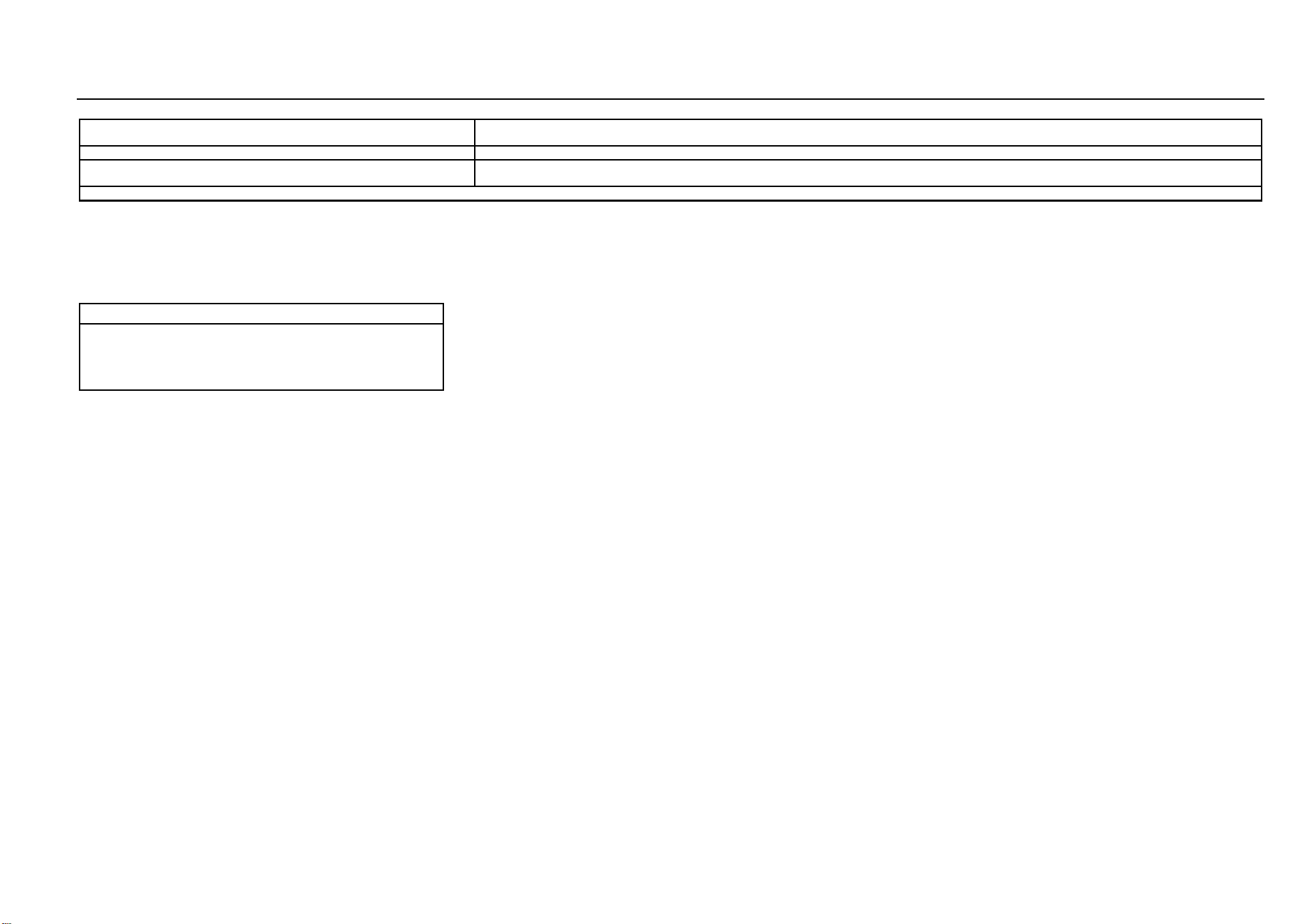
94 Audio Entertainment System
Songs stored in the memory device cannot be read.
Please confirm that the storage partition form of the memorizer is FAT16 or FAT32 as it is checked in the computer; if not, please make new setup on the computer
to change the format into a standard applicable to the device requirement.
MP3 songs cannot be read via an all-in-one USB adapter.
This device only supports song reading via an adapter with only one USB port.
Noise can be heard.
The noise can be produced by the device used to record the original audio file or it may be the noise existed at the time of recording. Please use other players to
play the file and then confirm whether the problem lies in this device.
If the fault still cannot be removed, please go to the Aftersales Service Center for inspection. Never disassemble the host to repair it on yourself.
Navigator Upgrading*
When the navigator cannot display comparatively new main
roads, it is time to update and upgrade the map data.
For details, please refer to the navigation system
instructions.
Note
After upgrading, the map may still fail to display all the
roads which are recently completed and open to
traffic. It is normal that certain roads can be displayed
only on an upgraded map of a followup version.

Temperature Control System 95
7
Temperature Control System
HVAC
Air Outlet ......................................................................... 96
Air Conditioning ............................................................... 98
Electronic Air Conditioning ..................................... 98
Temperature Control Thumbwheel ...................... 100
Fan Control Thumbwheel ..................................... 100
Air Distribution Mode Button ................................ 100
Internal Circulation Mode Button .......................... 102
Front Windshield Defroster Button ....................... 102
Rear Windshield Defroster Button ........................ 102
Manual Air Conditioning ....................................... 104
Air Conditioning System ....................................... 106
Air Conditioning (A/C) Button ............................... 107
Cool Air ................................................................ 107
Warm Air .............................................................. 107
Ventilation ............................................................ 108
Rapid Defrosting and Defogging .......................... 108
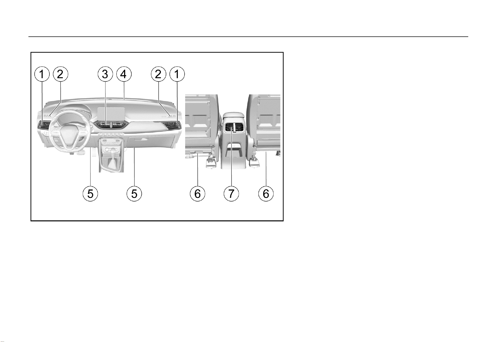
96 Temperature Control System
Air Outlet
1. Side air outlet
2. Front door window defogger air outlet
3. Central air outlet
4. Front windshield defogger air outlet
5. Floor air outlet
6. Front seat lower air outlet
7. Console air outlet*
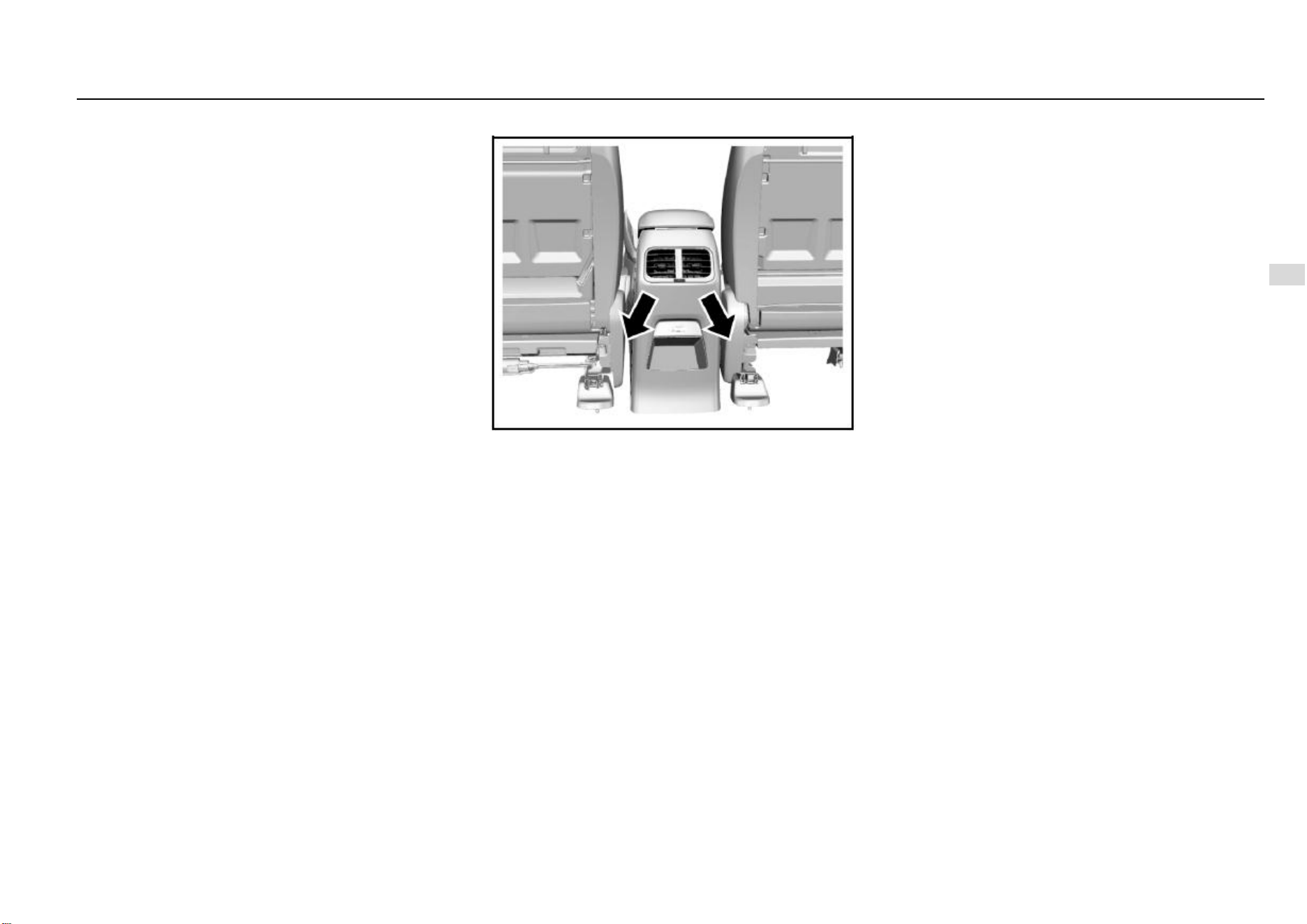
Temperature Control System 97
7
Temperature Control System
Side Air Outlet
You can divert the air to both sides of the front riding area
or the side door windows by operating the two adjustable
side air outlets. Beside each air outlet, an air volume
adjustment switch is located and you can operate the switch
to adjust the air volume.
Front Door Window Defogger Air Outlet
The front door window defogger air outlet is used to divert
the air to the side door window, mainly to the outside
rearview mirror area.
Central Air Outlet
You can decide the flow direction of the air from the two
adjustable central air outlets.
Front Windshield Defogger Air Outlet
The front windshield defogger air outlet is used to divert air
to the front windshield.
Floor Air Outlet
The floor air outlet is used to divert the air to the front foot
area.
Front Seat Lower Air Outlet
Air from the two front seat lower air outlets flows to the rear
foot area. Lower of the front seats shall be clear without
obstacles in case that air to the rear compartment is
blocked.
Console Air Outlet*
If equipped, the air outlets are located on the back of the
armrest between the two front seats. They can divert the air
to the rear passenger area.
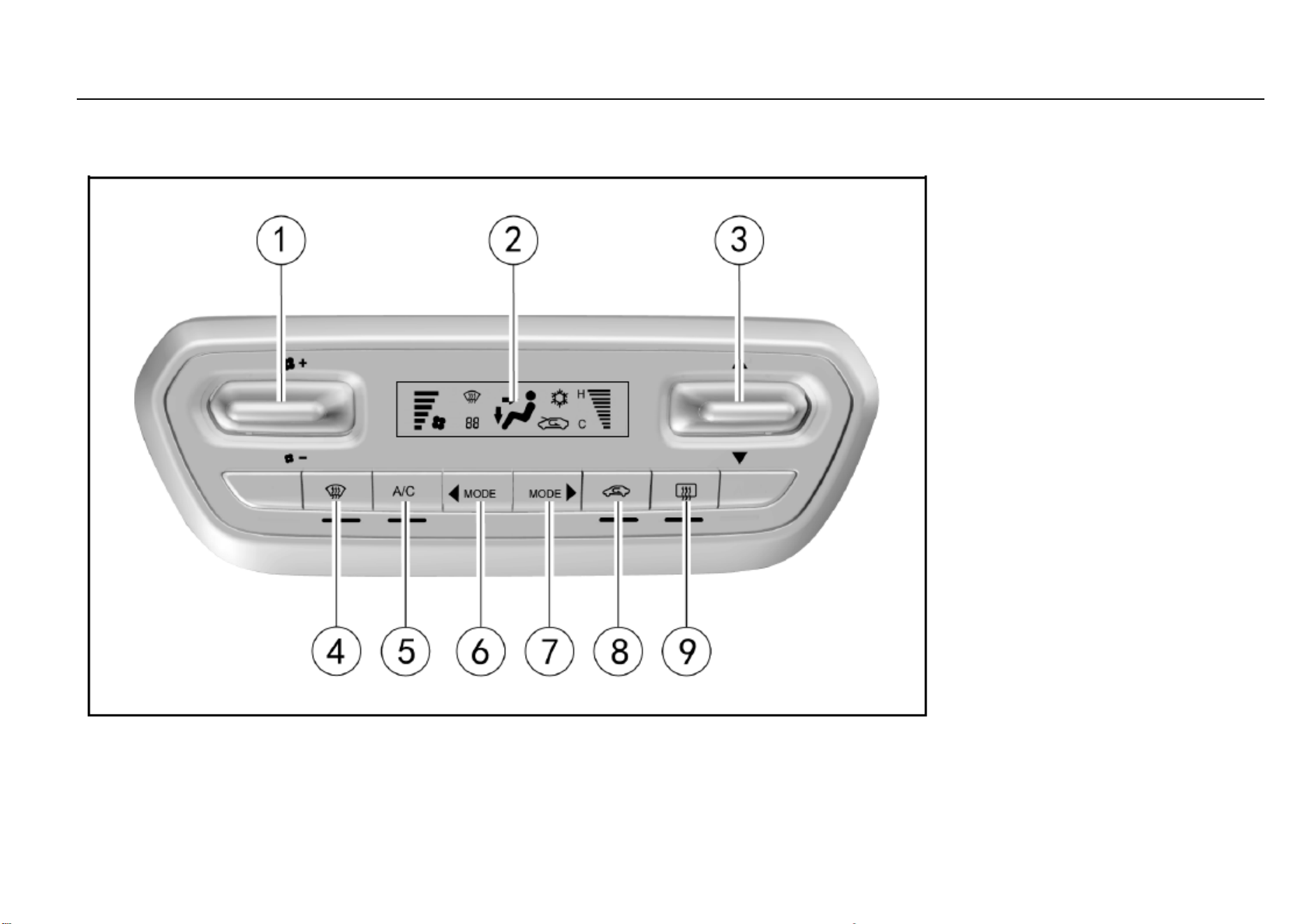
98 Temperature Control System
Air Conditioning
Electronic Air Conditioning
Air Conditioning Control Panel
1. Fan control thumbwheel
2. Display
3. Temperature control thumbwheel
4. Front windshield defroster button
5. Air conditioning (A/C) button
6. Mode selection button (backward)
7. Mode selection button (forward)
8. Internal circulation button
9. Rear windshield defroster button/outside rearview
mirror defroster button*
Note: Once the indicator below the button
illuminates, the corresponding function starts to
work.
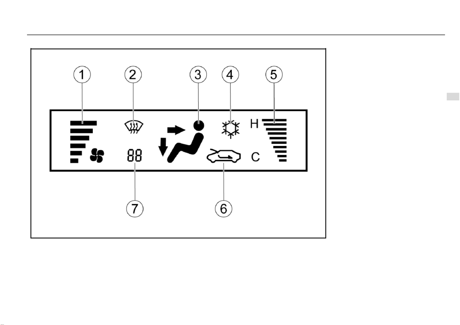
Temperature Control System 99
7
Temperature Control System
Display
1. Air volume
2. Front defrosting mode
3. Mode display (face blow, face blow/foot blow, foot
blow, foot blow/defroster, etc.)
4. Cooling mode
5. Temperature
6. Internal/external circulation mode
7. Fault code*
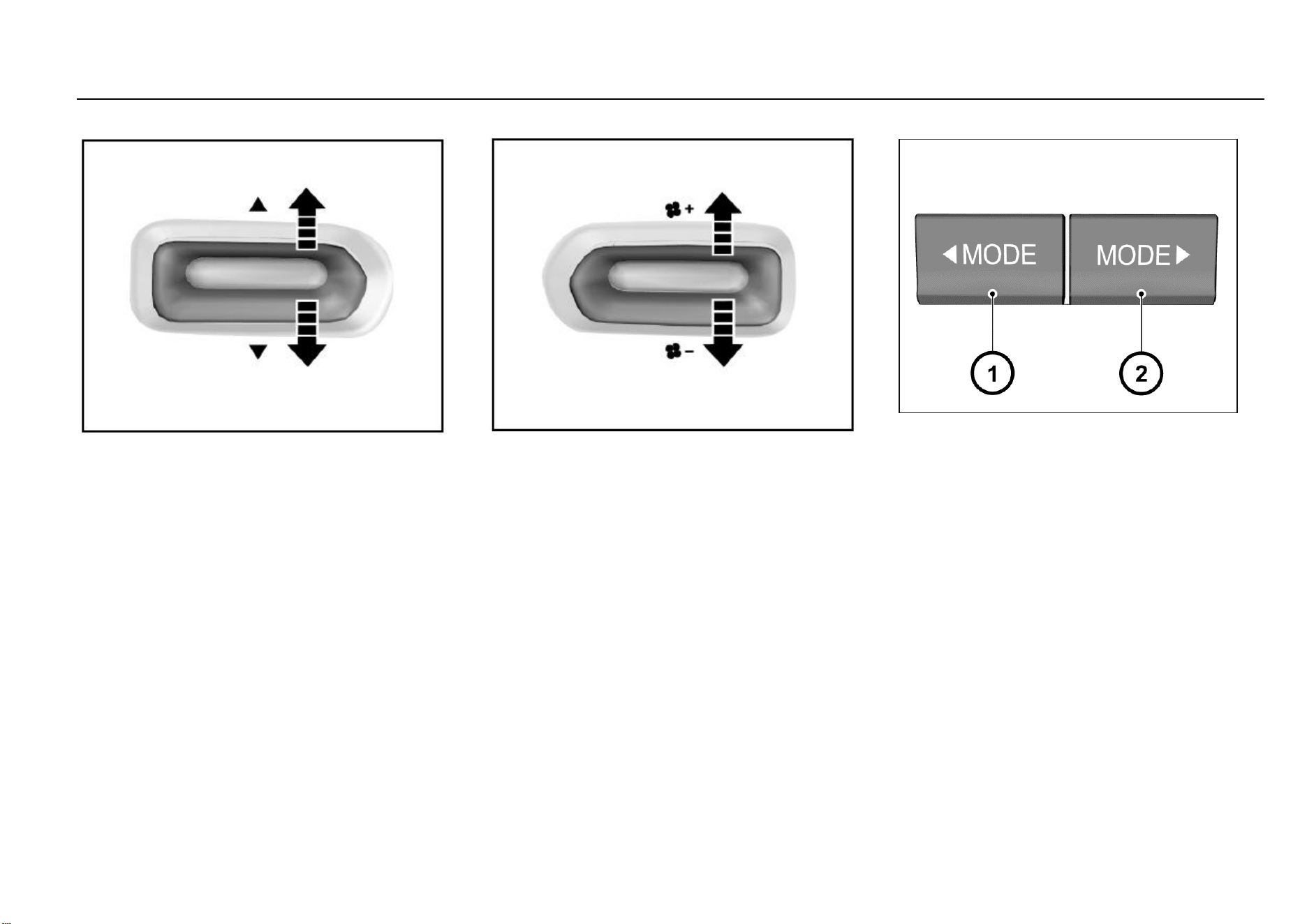
100 Temperature Control System
Temperature Control Thumbwheel
With the air volume switch is turned on, pull it
upwards/downwards to increase or decrease the
temperature. The temperature display bar on the display
screen displays the temperature accordingly. “H” represents
hot and “C” represents cool. Once the temperature reaches
the hottest (coolest) extent, if you pull the switch up again,
the temperature stays unchanged.
If you pull the temperature switch after the air conditioning
system has been turned off, the system starts again and the
start condition is shown on the display screen. At this time,
the air volume is set at Range 1 and other states restore to
the setups made before the system is turned off.
Fan Control Thumbwheel
Pull the thumbwheel upwards or downwards once to
increase or reduce the air volume by one range.
The air volume indication bar on the display screen displays
the corresponding range.
if the air volume is at Range 1, pull the thumbwheel
downwards once to turn off the air conditioning system.
If you pull upwards the fan switch after the air conditioning
system has been turned off, the air conditioning system
starts again and the start condition is shown on the display
screen. At this time, the air volume is set at Range 1 and
other states restore to the setups made before the system
is turned off.
Air Distribution Mode Button
Press the mode selection button to acquire the desired air
flow direction. You can set one of the four following air flow
directions by pressing the air distribution mode button:
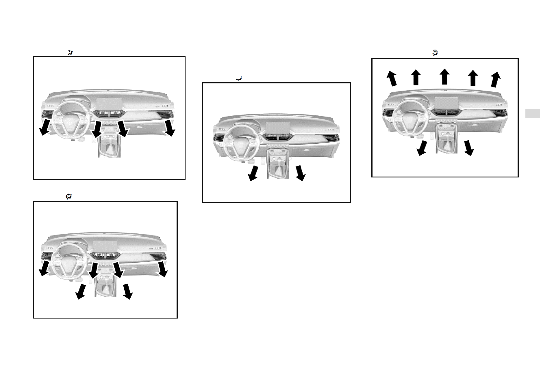
Temperature Control System 101
7
Temperature Control System
Face Mode ( )
In this mode, the air flows out from the central air outlet, the
side air outlet and the console air outlet*.
Dual Mode ( )
In this mode, the air flows in two directions. Half of the air
flows out from the floor air outlet and the front seat lower air
outlet; the remaining air flows out from the central air outlet,
side air outlet and console air outlet*.
Foot Mode ( )
Most of the air flows out from the floor air outlet and the front
seat lower air outlet; little amount of air flows out from the
windshield and front door window defroster air outlet and the
side air outlet.
Foot/Defroster Mode ( )
In this mode, air flows out from the front windshield defroster
air outlet, the front door window defroster air outlet, the floor
air outlet, the front seat lower air outlet and the side air
outlet.
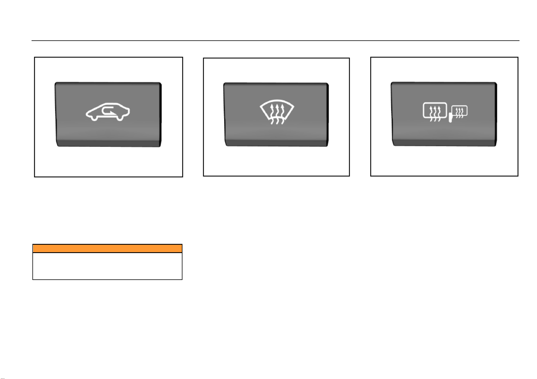
102 Temperature Control System
Internal Circulation Mode Button
You can press this button during driving on a dusty road, or
when you want to prevent the exhaust or outside smoke
entering inside, or when you want to quickly decrease or
increase temperature in the passenger area. The indicator
will illuminate and the inside air will start to circulate
internally. Press this button again to switch to the external
circulation mode and the indicator will go out. The system
memorizes the previously set air circulation mode the next
time you start the vehicle.
Caution
You may feel tired and sleepy after long-time driving
in the internal circulation mode.
Please switch to external circulation mode on a
regular basis to acquire fresh air.
Front Windshield Defroster Button
Press the button to select the front windshield defroster
mode.
Press the front windshield defroster button and the air
volume ascends to Range 4 automatically. If the air volume
is already higher than Range 4 before the button is pressed,
it will remain at the range.
As you switch from the air blow mode to the defroster mode,
the indicator below the button illuminates. As you turn on
A/C function, the indicator on the A/C button illuminates.
The air circulation mode switches to external circulation.
Press the button again to turn off the front defroster mode
and the system restore to the state before defrosting.
Rear Windshield Defroster Button
To turn on the defroster, first turn on the ignition switch and
then press the rear windshield defroster button. The
indicator on the button illuminates. Please turn off the
defroster after your view becomes clear.
After you press the button, the defroster will work for about
15 minutes and then turn off automatically.
If the vehicle is equipped with an outside rearview mirror
defroster, this defroster also works as the rear windshield
defroster works.
Temperature Control System 103
7
Temperature Control System
Caution
Lack of proper maintenance may cause damage to the
defroster or scratches on the glass.
It is not allowed to use any sharp cleaner or that prone
to cause glass wear to clean the rear windshield.
During vehicle cleaning or when operating near the
rear windshield, please take care not to shake or
damage the defroster wire.
If the driver’s view is affected, an accident can happen,
causing personal injuries, damage to the vehicle or
property loss.
Caution
Usage of the rear windshield defroster is prohibited
under the following circumstances:
● The engine is not running.
● Snow or ice has deposited on the rear windshield.
If you use the rear windshield defroster under these
circumstances, the vehicle battery can become under
voltage.
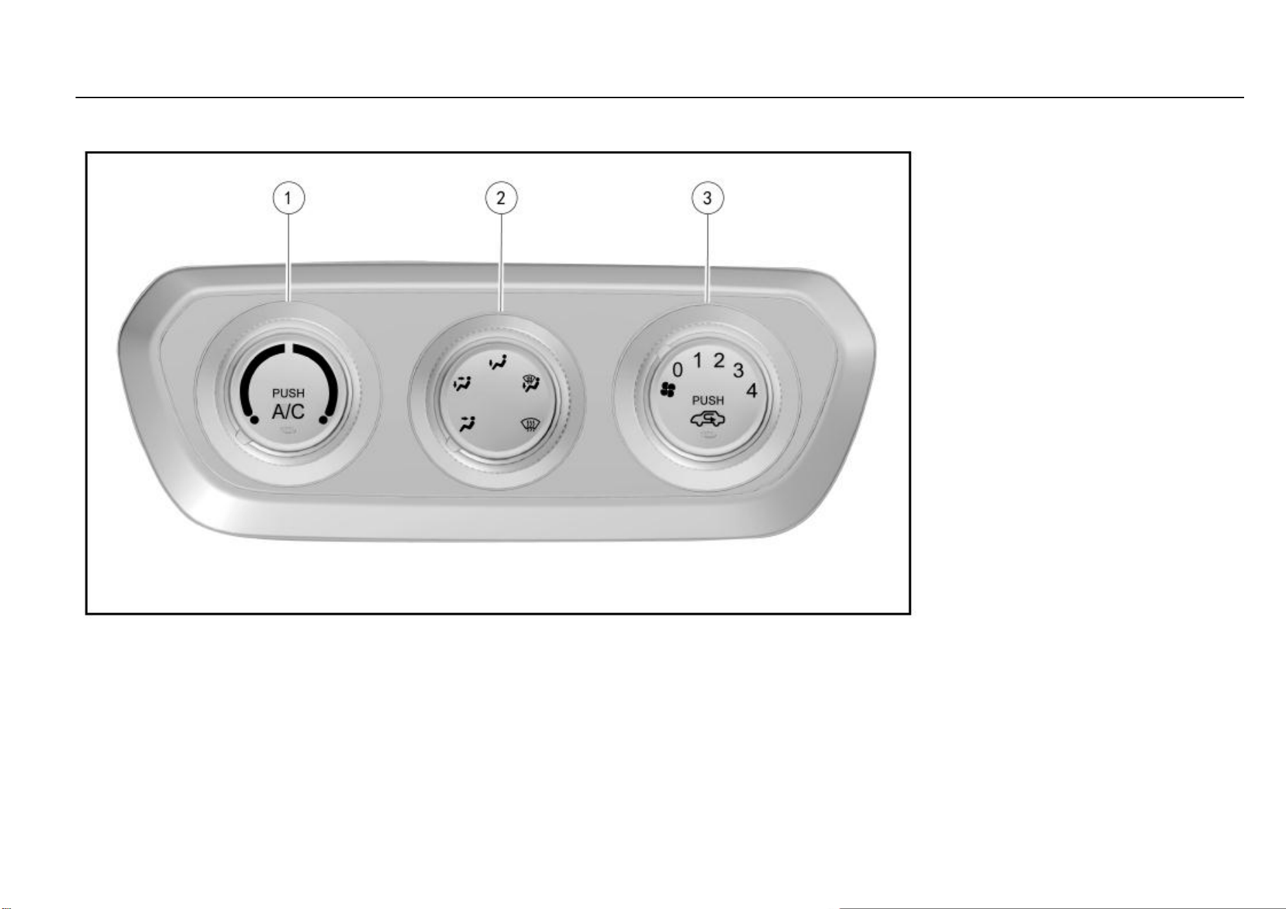
104 Temperature Control System
Manual Air Conditioning
Control Panel
1. Temperature control knob/air conditioning (A/C)
button
2. Air distribution mode button/rear windshield
defroster button*
3. Fan control knob/internal circulation button
Note: The position corresponding to the marker on
the button edge is just the selected function mode.
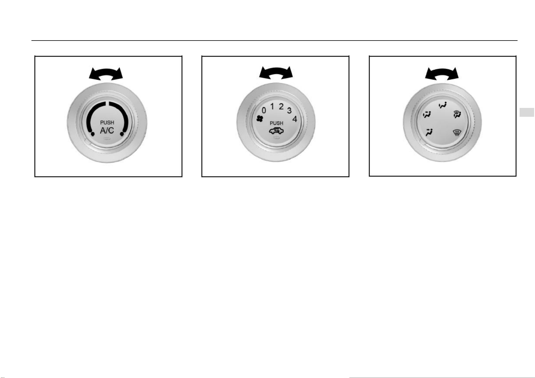
Temperature Control System 105
7
Temperature Control System
Temperature Control Knob
It is used to control temperature of the air flowing out from
the air outlet.
Turn the knob to the blue area and cool air comes out; to
the red area and warm air comes out.
Fan Control Knob
Turn the fan speed control knob to control the system air
flow.
A total of 4 ranges are available and the air volume is the
greatest at Range 4. Turn the knob to Range 0 and the air
conditioning system turns off.
Air Distribution Mode Knob
Adjust the air distribution knob to the desired mode so that
the air flows in the desired direction.
A total of 5 air blow modes are available and in each mode,
the air is controlled to flow out from the corresponding air
outlets. Please refer to the information provided above on
electronic air conditioning.

106 Temperature Control System
Internal Circulation Mode Button
You can press this button during driving on a dusty road, or
when you want to prevent the exhaust or outside smoke
entering inside, or when you want to quickly decrease or
increase temperature in the passenger area. The indicator
on the button illuminates and air starts to circulate inside the
vehicle.
Press this button again to switch to the external circulation
mode, the indicator will go out and outside fresh air enters
inside.
Caution
You may feel tired and sleepy after long-time driving
in the internal circulation mode, so please switch to
the external mode on a regular basis to acquire fresh
air.
Rear Windshield Defroster Button*
To turn on the rear windshield defroster, first turn on the
ignition switch and then press the rear windshield defroster
button. The instrument on the button will illuminate. Please
turn off the defroster after your view becomes clear. The
defroster will also turn off automatically after working for
about 15 minutes.
Caution
Lack of proper maintenance may cause damage to the
defroster or scratches on the glass.
It is not allowed to use any sharp cleaner or that prone
to cause glass wear to clean the rear windshield.
During vehicle cleaning or when operating near the
rear windshield, please take care not to shake or
damage the defroster wire.
If the driver’s view is affected, an accident can happen,
causing personal injuries, damage to the vehicle or
property loss.
Caution
Usage of the rear windshield defroster is prohibited
under the following circumstances:
● The engine is not running.
● Snow or ice has deposited on the rear windshield.
If you use the rear windshield defroster under these
circumstances, the vehicle battery can become under
voltage.
Air Conditioning System
Refrigerating device of the air conditioning system is used
to cool down the inside air and remove the moisture and
dust contained in the air.
If the temperature control knob is already set to a
comparatively high temperature, warm air will be generated
inside the vehicle even though the air conditioning
refrigeration (A/C) function is activated.
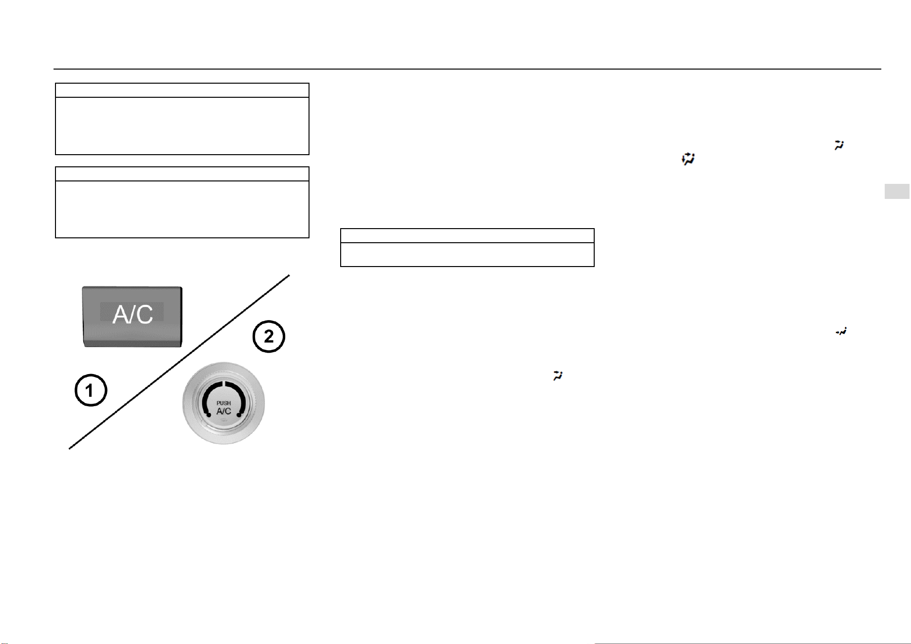
Temperature Control System 107
7
Temperature Control System
Note
After the air conditioning system is turned on, you can
find water drops in the lower area of the engine
compartment. The water drops are formed as moisture
in the air condenses on surface of the air conditioning
system component, which is a normal phenomenon.
Note
As the air conditioning compressor works, it
consumes certain engine power. This is the reason
why you may find that the vehicle power performance
decreases when the air conditioning refrigeration
function is activated.
Air Conditioning (A/C) Button
To turn on the air conditioning (A/C) system:
1. Start the engine.
2. Press the air conditioning (A/C) button. The button
indicator illuminates, indicating that the air
conditioning system is working.
3. Adjust the fan speed.
To turn off the air conditioning system:
Press the air conditioning (A/C) button again. The button
indicator goes out, indicating that the air conditioning
system has stopped refrigeration.
If the air conditioning system was kept on when the engine
was shut down the last time, the system will turn on
automatically as the vehicle is started next time.
Note
Note
The air conditioning system cannot work if the fan
control thumbwheel is turned to OFF position.
Cool Air
Fast Cooling
To cool down fast in scorching hot days or after the vehicle
is kept under the blazing sun for a long time:
1. Open the door windows a little to expel the hot air inside.
2. Turn on the air conditioning (A/C) system. (The indicator
illuminates at this time.)
3. Activate the internal circulation mode.
4. Switch the air distribution mode to face mode ( ).
5. Adjust the temperature to the maximum coolness.
6. Adjust the fan speed to the maximum.
Normal Cooling
1. Turn on the air conditioning (A/C) button. (The indicator
illuminates at this time.)
2. Activate the internal circulation mode.
3. Switch the air distribution mode to face mode ( ) or dual
mode ( ).
4. Adjust the temperature to the cool air area.
5. Adjust the fan speed to the desired value.
Warm Air
Rapid Heating
Activate the rapid heating mode to increase the passenger
area temperature quickly. It is prohibited to activate this
mode for a long time, otherwise the inside air quality will
decrease and fog can form on the windows. To clear up the
fog on the windows, turn off the internal circulation mode so
that fresh air enters inside.
To acquire the warmest air:
1. Turn off the air conditioning (A/C) system. (The indicator
goes out at this time.)
2. Activate the internal circulation mode.
3. Switch the air distribution mode to foot mode ( ).
4. Adjust the temperature to the maximum warmness.
5. Adjust the fan speed to the maximum.
108 Temperature Control System
Normal Heating
1. Turn off the air conditioning (A/C) system. (The indicator
goes out at this time.)
2. Activate the external circulation mode.
3. Switch the air distribution mode to foot mode ( ) or dual
mode ( ).
4. Adjust the temperature to the warm air area.
5. Adjust the fan speed to the desired value.
Ventilation
Dual Mode
This mode is applicable to cool and sunny days. Warm air
is controlled to flow to the floor area and outside cool air is
controlled to flow to upper portion of the compartment.
The method to use this setup is:
1. Activate the external circulation mode.
2. Switch the air distribution mode to dual mode ( ).
3. Adjust the temperature to the desired value.
4. Adjust the fan speed to the desired value.
Ventilation
To control the air to flow out from the central air outlet and
the side air outlet:
1. Turn off the air conditioning (A/C) system. (The indicator
goes out at this time.)
2. Activate the external circulation mode.
3. Switch the air distribution mode to face mode ( ) or dual
mode ( ).
4. Adjust the temperature to the cool air area.
5. Adjust the fan speed to the desired value.
Rapid Defrosting and Defogging
Please operate in the following steps in cold weather:
Air conditioning switch (A/C): ON (southern area) or
OFF (northern area)
Air inlet mode: to external circulation
Air distribution mode:
Temperature switch: to warm air
Air volume switch: to the maximum
To keep the front windshield clean and divert warm air
to the floor, please choose foot/defroster ( ) mode.
Please operate in the following steps if not in cold
weather:
Air conditioning switch (A/C): ON
Air inlet mode: internal circulation ( ); switch to
external circulation after the fog has lift.
Air distribution mode: or .
Temperature switch: to the area that ensures
passenger comfort.
Air volume switch: to the maximum
Note
At the beginning of defrosting and defogging with the
warm air, the fog can become thicker, please take care
to ensure driving safety.

Driving and Controls 109
8
Driving and Controls
Driving and Controls
Driving Instructions ................................................................ 110
Vehicle Control ............................................................ 110
Emergency Measures.................................................... 110
Start and Operation ................................................................. 111
Trial Run of New Vehicle ............................................ 111
Mechanical Ignition Switch Position* .......................... 112
ENGINE START STOP Switch Position* ................... 112
Electronic Steering Column Lock* .............................. 113
Engine Starting ............................................................. 113
ENGINE START STOP Function* .............................. 114
Cruise Control System * ............................................... 115
Engine Immobilizer System ......................................... 116
Parking ......................................................................... 116
MT Transmission * ................................................................. 117
Operation for Shifting Transmission with Six Drive Gears
to reverse (R) gear ........................................................ 117
Brake ....................................................................................... 118
Anti-lock Brake System (ABS) .................................... 118
Electric Brake Force Distribution (EBD) System ......... 120
Electronic Stability Control (ESC) System................... 120
ESC OFF Switch .......................................................... 120
Hill-start Hold Control (HHC) System * ...................... 121
Parking Brake ............................................................... 121
Electric Power Steering (EPS) System .................................... 122
Fuel ......................................................................................... 123
Fuel Suggestions........................................................... 123
Fuel Filling ................................................................... 124
110 Driving and Controls
Driving Instructions
Vehicle Control
Do not slide in case that the engine is out of operation.
In such case, many systems (such as brake booster) cannot
function. Driving in this way will form a danger to yourself
and others.
Pedal
To ensure that the pedal travel is unhampered, the floor mat
in the pedal area shall not be excessively thick, and no
article shall be placed in the pedal area.
Emergency Measures
Caution
The operation time of the starter motor shall not
exceed 10s once. Otherwise, the starter motor will get
damaged or discharge of battery will occur.
One Tire is Punctured When the Vehicle is Running
If one tire is punctured when the vehicle is running, the
driver shall hold the steering wheel tightly to control the
driving direction, slowly decelerate, turn on the hazard
flasher, and gently depress the brake pedal to park your
vehicle in a safe area.
Warning
Do not brake suddenly when one tire is punctured.
Braking suddenly will cause the vehicle to tilt towards
one side, and thus an accident may be caused.
One Fault Exists When the Vehicle is Running
If one fault exists when the vehicle is running, the driver shall
turn on the hazard flasher, slowly decelerate, and park the
vehicle in a safe area at the curb.
Place a warning triangle at a position 50 m behind the
vehicle in the daytime while placing it at a position 100 m
behind the vehicle at night. Please follow requirements of
traffic laws and regulations.
After inspection, send the vehicle to the Aftersales Service
Center for inspection and maintenance.
Place the warning triangle in the luggage compartment, or
have the customer give it to you when the vehicle is being
delivered.
If the Engine Does Not Work
In case that the ignition switch is at the START position, if
the starter motor does not work, please check whether the
battery is dead, whether the battery port is connected
correctly and whether relevant fuses get damaged.
If the starter motor works but the engine fails to be started,
please check fuel level, fuel filter, fuel pump, relevant wiring,
etc.
The operation condition of the fuel pump can be
preliminarily judged by hearing sounds made by the ignition
switch when it is being turned on.
Measures Taken in Case of Engine Overheat
When the vehicle is running, if the output power of the
engine reduces suddenly or the warning lamp on the
instrument indicating excessively high temperature
illuminates, park your vehicle in a safe area and take
following measures:
Have the engine run at idle, and turn the transmission
at the neutral position.
Pull the parking brake lever.
Turn off the A/C.
Open the bonnet to ventilate the engine bay.
If the level of the coolant reservoir does not drop, stop
the engine to cool it.
If the coolant level is very low, uncover the reservoir,
slowly fill water in the reservoir drop by drop till the
level reaches the MAX (maximum) level mark of the
coolant reservoir.
After taking provisional measures, immediately send
the vehicle to the Aftersales Service Center for
inspection.
Warning
Do not open the bonnet if steam or coolant overflows
from engine parts. Otherwise, you may be scalded by
steam or coolant.
Driving and Controls 111
8
Driving and Controls
Caution
Suddenly filling cold water in the overheated engine
will damage the engine.
The handling method above is taken in case of an
emergency. When the engine gets overheated, you are
suggested to contact the Aftersales Service Center for
solution.
Caution
When the engine gets heated, uncovering the coolant
reservoir will get steam or coolant overflowed, and
thus your face or other body parts may be scalded.
If you are to uncover the coolant reservoir, you can do
it after the engine cools down completely. Apply one
cloth to the cover, open it slightly at first (by 1/3-1/2),
and then open it fully after pressure in the reservoir is
released completely.
Operation in Heavy Snow
Decelerate when the vehicle turns a corner, upgrades
or crosses a bridge.
Please avoid parking on a hard road shoulder;
otherwise the snow shoveling work will be obstructed.
Please keep safe distance from other vehicles;
braking unnecessarily will be limited.
Clear the accumulated snow around the vehicle
frequently, for such measure can prevent the exhaust
pipe from being blocked.
Start and Operation
Trial Run of New Vehicle
Following measures can be taken within the initial mileage
of 500 km, which can improve the performance, promote the
vehicle economy and extend the service life:
Avoid starting the engine by depressing the
accelerator fully.
Do not keep the engine idling for a long time.
Avoid any emergency shutdown except in an
emergency. With this, the brake can run in well.
Do not quickly start, accelerate suddenly and
continuously keep the vehicle running at high speed if
possible, to avoid any damage to the engine and save
the fuel.
Avoid accelerating by depressing the accelerator fully
at a low gear and driving by depressing the
accelerator greatly.
Do not drag any other vehicle.
Note
Please do not use such electric equipment as audio
and head lamp for a long time under the condition that
the engine is off. When getting out of the vehicle,
please shut down the electric equipment for the
vehicle, to avoid the battery from running out; if the
battery runs out, the vehicle may fail to be started.
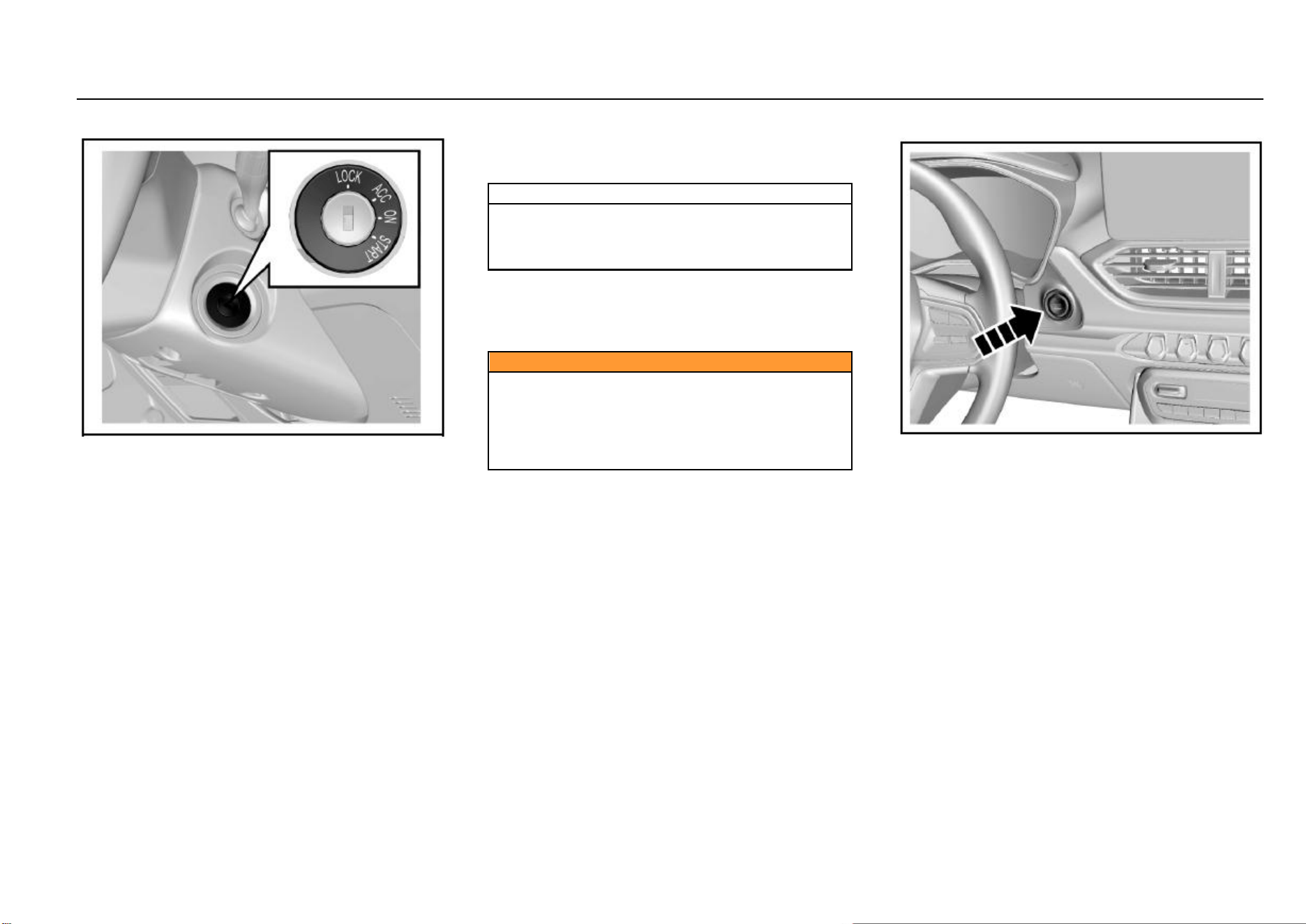
112 Driving and Controls
Mechanical Ignition Switch Position*
When the ignition switch is turned at the right side of the
steering column, the operating positions are as follows:
LOCK, ACC, ON and START.
● LOCK
Lock the steering wheel. Remove the key and turn the
steering wheel till the steering wheel is locked.
If you cannot turn the key when unlocking the steering
wheel, you can gently turn the steering wheel to right/left for
one thing and turn the key for another.
● ACC
The engine can be shut down when the ignition key is turned
to the ACC position without the need to lock the steering
wheel. If you are to turn the ignition key from the ACC
position to the LOCK position, you can gently press in the
key and turn the key to the LOCK position.
When the ignition key is at the ACC position, some electrical
accessories such as radio and cigar lighter can be used.
● ON
Connect the ignition system and electrical accessories.
Note
Do not keep the key at the ACC position and the ON
position for a long time when the engine is out of
operation; otherwise the battery will be in insufficient
voltage.
● START
Start the engine. After starting the engine, release the key;
the key will automatically return to the ON position.
Confirm that the engine does not operate before turning the
ignition key to the START position.
Caution
Never remove the key or turn the key switch when the
vehicle is running.
Otherwise, the brake assistance will disappear and the
steering wheel may be locked. Therefore, the driver
will lose control of the vehicle and thus the vehicle
damage and the casualty accident may be caused.
ENGINE START STOP Switch Position*
If equipped, the ENGINE START STOP switch is at the
lower right side of the instrument cluster.
Working indicator on ENGINE START STOP switch:
Orange: It indicates that the ignition switch is at the ACC or
ON position.
Green: It indicates that the start conditions are met.
When the working indicator turns green, if the transmission
is at the neutral position, press the start switch and then the
engine can be started.
When the power is switched from the low voltage to the high
voltage, the system must be able to detect the legal key.
Please place the key at one position near the ENGINE
START STOP switch inside the vehicle, such as driver’s
pocket or instrument panel storage box.

Driving and Controls 113
8
Driving and Controls
In the sequence from the low voltage to the high voltage of
power, the operating positions are as follows: LOCK, ACC,
ON and START.
● LOCK
Parking is carried out at the position. The working indicator
on the ENGINE START STOP switch does not illuminate
and the vehicle power is off.
● ACC
Press the ENGINE START STOP switch at the LOCK
position; the position can be switched to the ACC position.
The orange working indicator on the ENGINE START STOP
switch starts to illuminate. At the position, power supplies of
some electrical accessories such as audio and cigar lighter
are connected.
If no operation is conducted, the system will automatically
return to the LOCK position 1h later, so as to reduce the
consumed power.
● ON
Driving and start are conducted at the position.
Press the ENGINE START STOP switch at the ACC
position once; the position can be switched to the ON
position. The instrument cluster indicator illuminates, and
the orange indicator on the ENGINE START STOP switch
illuminates.
If you press the ENGINE START STOP switch once
(without other operations) at the ON position, the switch will
be turned to LOCK position.
● START
At the ON position, turn the transmission at the neutral
position, and depress the clutch pedal . Then the green
indicator on the ENGINE START STOP switch illuminates.
Press the ENGINE START STOP switch once, and the
engine will start. After the engine starts, the ignition switch
keeps at the ON position.
● OFF
Press the start switch once (vehicle speed < 2 Km/h).
Note
Never keep the engine idling at high speed for over 5
min.
Excess temperature will damage the exhaust system.
Note
If the transmission is not at the neutral position, the
engine cannot start.
Electronic Steering Column Lock*
As the electronic steering column lock is used to lock the
steering wheel, the vehicle having the ENGINE START
STOP function is equipped with the electronic steering
column lock at the same time. You can hear the operating
sound when the lock device is started or released.
If locking the steering wheel is required, following conditions
shall be met at the same time:
1. The vehicle is motionless;
2. The ignition switch is at the LOCK position.
When conditions above are met, the steering wheel will be
locked immediately if any one of following actions occur:
Open or close the left front door.
Remote locking
Wait 24s later
If unlocking the steering wheel is required, you can just
enter the vehicle with the legal key and press the ENGINE
START STOP switch.
In the case that the steering column lock may be unable to
be released when it is in the wheel-deviation forward
direction, the instrument cluster will display “Failure in
locking of electronic steering lock” and buzz for prompt. At
this time, align the steering wheel, turn the ignition switch at
the ON position, and then switch to the LOCK position, to
make efforts to unlock the steering wheel. If unlocking fails,
check the vehicle.
Engine Starting
Before starting the engine:
Ensure that no barriers exist around the vehicle.
Ensure that all windows and doors are clean and
transparent.
114 Driving and Controls
Check whether the tire conditions and the inflation
pressure are proper and whether foreign matters
exist.
Adjust the seat headrest to a proper position.
Adjust the rearview mirrors inside/outside the vehicle.
Fasten the safety belt and ask all passengers to
fasten safety belts.
When turning the key at the ON position, check the
operating conditions of the warning lamp and the
indicator on the instrument panel.
Regularly (e.g., when refueling) check the
maintenance items recorded in the Manual.
Engine Starting:
1. Apply the parking brake.
2. Ensure that seats and rearview mirrors are at proper
positions. Adjust them if necessary.
3. Turn the ignition switch at the ON position.
4. Ensure that the gearshift lever is at the neutral
position, and then depress the clutch pedal fully.
5. Do not depress the accelerator pedal, turn the
ignition-switch key to the ON position, and release the
clutch (or brake) pedal after the engine starts. For one
model having the ENGINE START STOP function,
click the ENGINE START STOP switch once to start
the engine. If the engine starts temporarily and fails to
operate, you can wait for 10s and then try again.
6. Keep the engine idling for more than 30s to heat the
engine.
7. Release the parking brake.
8. Do not drive the vehicle at high speed before the
engine temperature reaches the normal operating
temperature.
Note
Keep the engine idling for 3-5 min before the vehicle
with the turbocharged engine starts to run, especially
in winter or after storage for a long time, and after the
engine oil is changed or the engine is maintained.
Note
● Do not keep the starter running continuously for
over 10s.
● It may be difficult to start the vehicle in extremely low
temperature.
● It may be difficult to start the vehicle in one high-
altitude area.
● If the engine fails to start, please wait for 10s and
then restart so as to avoid any damage to the starter.
Turbocharged Engine Shutdown
After keeping the turbocharged engine operating at high
speed for a long time, please firstly keep it idling for 3-5 min
and then kill it, so as to cool the turbocharger. Otherwise,
the turbocharger may get damaged due to overheat.
Note
Avoid the turbocharged engine from idling for a long
time; the idling time shall not exceed 20 min.
ENGINE START STOP Function*
Start Condition
Following conditions shall be met for engine start:
1. The legal key is inside the vehicle;
2. Depress the clutch pedal.
If conditions above are met, the green indicator on the
ENGINE START STOP switch will illuminate. In this case, if
the gear is at the neutral, press the start switch and the
engine will immediately start.
Other Control Instructions
1. Emergency start
The brake or clutch switch failure will make the start
conditions unable to be met, and thus the engine
cannot start in the normal procedures. You can firstly
turn the ignition switch at the ACC position, confirm
that the transmission is at the neutral, and then long
press the ENGINE START STOP switch for 15s. In
this case, emergency start of the engine succeeds.
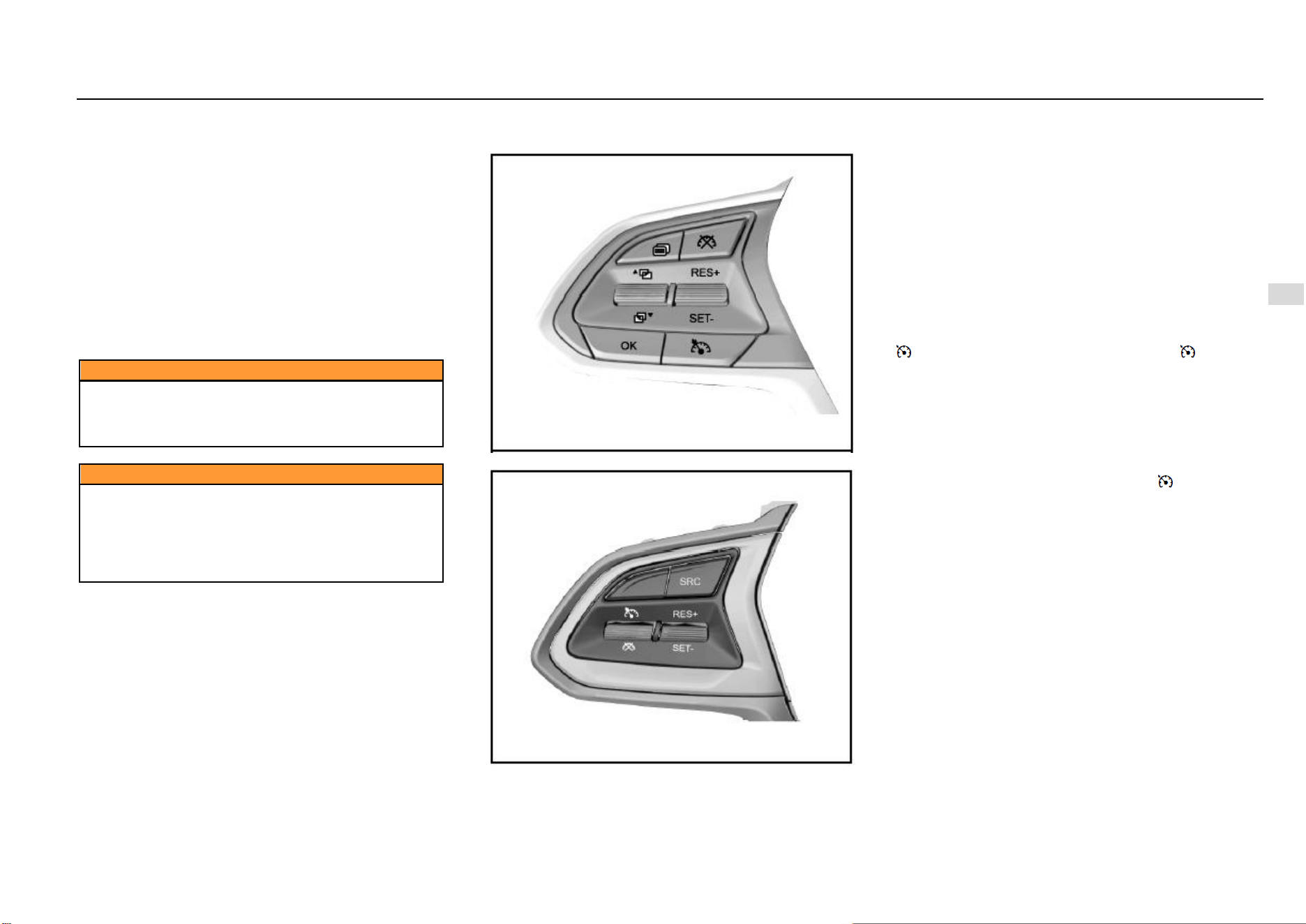
Driving and Controls 115
8
Driving and Controls
Insufficient battery of the remote key may cause the
system to fail to search for the key and thus the engine
fails to start. In this case, you can firstly depress the
clutch pedal, and at the same time attach the side of
remote key with the Baojun emblem close to the
ENGINE START STOP switch. When the green
indicator on the ENGINE START STOP switch
illuminates, press the switch to start the engine.
Please try again if you fail. You shall replace the
battery of the remote key.
2. Emergency flameout
If emergency flameout of the engine is required when the
vehicle is running, you can long press the ENGINE START
STOP switch for 2s or continuously press for 3 times within
3s.
Caution
Never have a kid operate the ENGINE START STOP
switch in any case; otherwise unexpected start or
flameout of the vehicle, and the vehicle damage and
the casualty accident may be caused.
Caution
Never operate the ENGINE START STOP switch when
the vehicle is running. Accidental vehicle flameout
may suspend braking and assistance of the steering
system. In this case, the driver will lose control of the
vehicle and thus the vehicle damage and the casualty
accident may be caused.
Cruise Control System *
Type I Switch
Type II Switch
As the switch of cruise control system is at the steering
wheel, when the cruise control system is started, the vehicle
can run at such speed. Depress the brake pedal, and the
function will be immediately disabled. Except that the brake
pedal is used to disable the function, operating switches
such as parking brake switch and clutch switch can also be
used to disable the function of the cruise control system.
The system can be used at 3, 4, 5 and 6 gears with the
speed range of 40 Km/h - 120 Km/h when the engine speed
is lower than 4800 rpm. For the AT model, the minimum
speed for starting the cruise control system is 48 Km/h.
Specific application method:
First Step: Cruise Start
Based on the cruise control system switch type, press the “
” button or pull the toggle button towards “ ” direction,
and then the cruise indicator on the instrument cluster starts
flickering, indicating that the cruise control system enters
the activated state; pull the toggle button towards the “SET/-
” direction, and the cruise start succeeds and the cruise
indicator of instrument is normally on. (For example, when
the driver intends to stabilize the speed at 100 km/h, the
driver must firstly speed up to 100 km/h. When the speed
reaches 100 km/h, he/she shall press the “ ” toggle button
and then pull the toggle button towards the “SET/-” direction.
At this time, release the accelerator pedal, and the vehicle
will continuously run at the speed of 100 km/h). After setting
the cruising speed, you can also use the accelerator pedal
to accelerate in the normal method; after the accelerator
pedal is released, the system will recover the speed to the
original cruising speed.
116 Driving and Controls
Second Step: How to Deactivate Cruise
If you are to immediately decelerate in case of any
emergency in front during cruise control, you can depress
the brake pedal or clutch pedal, or press the cruise
deactivation button “ ” or pull the toggle button towards “
” direction. In this case, the vehicle exits from the current
cruise state and enters the cruise activation state, and the
cruise indicator of instrument flickers; if you press the “ ”
button or pull the toggle button towards “ ” button in the
cruise state, the whole cruise system will be deactivated and
the instrument indicator will go out.
Third Step: Operation for Cruise Recovery
When the vehicle exits from the cruise state and enters the
cruise activation state, if you are to carry out the cruise
control at the previous cruising speed, you just need pull the
toggle button once towards the “RES/+” direction. Then
cruise control is carried out at the previously-saved speed
recovered. For example, the cruising speed is 60 Km/h
before braking and becomes 50 Km/h after braking, and at
the time the cruise indicator of instrument flickers. Pull the
toggle button once towards the “RES/+” direction; the cruise
indicator will be normally on, and the vehicle will
automatically speed up to 60 Km/h and enter the cruise
control state.
Fourth Step: How to Promote Cruise Control Speed
Pull the toggle button towards the “RES/+” direction and the
set cruising speed will rise without the need to depress the
accelerator pedal. The speed will rise by 2 km/h every time
you pull up the switch once. If the toggle button is kept
pressed, the vehicle speed will continuously rise. Once the
switch is released, the then running speed will be saved into
the memory and the vehicle will cruise at the speed.
Fifth Step: How to Reduce Cruise Control Speed
Pull the toggle button towards the “SET/-” direction to
reduce the cruising speed. The speed will reduce by 2 km/h
every time you pull down the switch once. If the toggle
button is kept pressed, the vehicle speed will continuously
reduce. Once the control lever is released, the then running
speed will be saved into the memory and the vehicle will
cruise at the speed. If the toggle button is released when
the vehicle speed reduces to about 40 km/h (less than 40
km/h), the saved value will be deleted. If you are to
continuously drive at the cruise control speed, you need
reset the cruising speed.
Caution
In principle, the cruise control system can be used on
one expressway or one totally-closed road.
It is not allowed to use the cruise control system in
rainy, icy and snowy weather, and on one densely-
hillside road or densely-crooked road.
Cruise control is also not proper on a rugged
pavement and when too many vehicles run on one
road.
Note
For the MT model, after the cruise control system is
started, if you intend to shift the transmission to the
neutral position, always depress the clutch pedal
firstly. Otherwise, it may cause the engine to
overspeed and thus get damaged.
Engine Immobilizer System
The vehicle with the engine immobilizer system has the
extra anti-theft capacity, for the system can prevent any
unauthorized person from starting the vehicle. The matching
key of the engine immobilizer system has been encoded
electronically. The electronic transceiver is concealed in the
ignition key. Only a valid key can be used to start the engine.
However, an invalid key can also be used to open doors.
The engine immobilizer system isolates the power supply
from the ignition system, the fuel pump and the fuel injector.
When any unauthorized person turns the invalid key to the
START position, the engine immobilizer system fails to
identify the electronic code. Therefore, the engine cannot
start and the immobilizer system indicator will be flickering.
Note
If the vehicle is equipped with one steering wheel
mechanical lock again, a better anti-theft result will be
realized.
Parking
When the parking brake is used for parking, the button
shall be released after parking. When parking on a
ramp, tension the parking brake as tightly as possible
and depress the brake pedal at the same time.
Shut down the engine and turn off the ignition switch.
Turn the steering wheel till the steering wheel is
locked by the steering wheel lock.
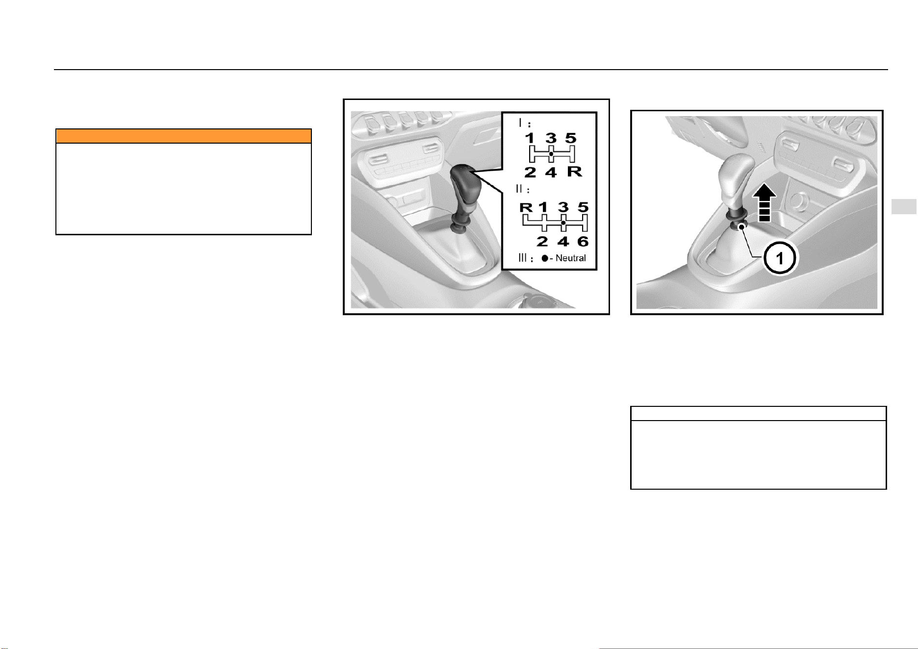
Driving and Controls 117
8
Driving and Controls
When parking the vehicle on one uphill ramp, turn the
front wheels away from the road shoulder.
When parking the vehicle on one downhill ramp, turn
the front wheels towards the road shoulder.
Caution
Do not park and drive the vehicle on inflammables
such as straw and hay. If such inflammables cannot
be avoided, park the vehicle to check and confirm that
these inflammables are not attached at the chassis
after the vehicle passes the inflammables.
Otherwise, these inflammables may be ignited by
high-temperature components on the chassis, and
thus a fire accident is caused.
MT Transmission *
Shift the gear as per gear positions marked on the gearshift
lever ball after the clutch is released. If you have to shift to
the reverse gear, you must firstly stop the vehicle,
completely depress the clutch pedal, and then shift the
gearshift lever from the neutral (N) gear to the reverse (R)
gear.
1: First drive gear 2: Second drive gear
3: Third drive gear 4: Fourth drive gear
5: Fifth drive gear 6: Sixth drive gear (if any)
R: Reverse gear
Depress the clutch pedal completely when shifting gear. Do
not always put your foot on the clutch pedal during driving.
Operation for Shifting Transmission with Six
Drive Gears to reverse (R) gear
As shown in the figure above, when shifting the
transmission with six drive gears to the reverse (R) gear,
pull up the reverse gear lock ring firstly and then turn the
gearshift lever from the neutral (N) gear to the reverse (R)
gear.
Take care not to pull the reverse gear lock ring when shifting
to the drive gear, so as to avoid from shifting to the reverse
gear accidentally.
Note
When shifting between the drive gear and the reverse
gear, be sure to ensure that the vehicle comes to a
complete stop. After completely depressing the
clutch, wait for a moment and engage a gear.
Otherwise, the transmission may get damaged or the
transmission service life may be shortened.
118 Driving and Controls
Note
When reversing your vehicle, please slowly start and
confirm that the vehicle is shifted to the reverse (R)
gear, for engaging a wrong gear may cause an
accident.
Warning
Always putting your foot on the clutch pedal during
driving will damage the engine and the clutch system
and increase the consumed fuel volume.
Brake
The brake system is designed for the braking performance
under the driving conditions in wide range. In the braking
process, the vehicle speed is reduced through the braking
friction and the friction between tires and ground. It is normal
that small braking friction sounds and friction sounds
between tires and ground are given with no need for special
treatment; it is also normal that occasional squeals are
given in braking. Squeals may be produced for such causes
that other matters may adhere to the friction faces during
operation of the vehicle, the vehicle is out of operation for a
long time, or friction faces get rusted after raining. If squeals
are produced at a lower frequency, there is no need for
special treatment.
To avoid the pedal travel from being influenced, do not lay
a thick carpet in the brake pedal area.
If you find that the brake pedal fails to return or the brake
pedal travel becomes longer, we strongly advise you to
have your vehicle inspected at the Aftersales Service
Center. This may indicate a faulty brake system.
Note
When you drive your vehicle in one high-altitude area,
continuously braking may cause the brake pedal force
to increase.
Note
To run in the friction plate and the brake disc and
confirm the performance and the service life, after
purchasing a vehicle and installing new friction plates,
you had better avoid emergency braking or braking for
a long time within millage of 200 km.
Warning
Please check whether the stop lamp is normal before
driving your vehicle. Keep the vehicle running at low
speed after starting the vehicle, and check the braking
performance. You shall do more like this especially
after your vehicle is just washed. The wet brake may
cause an accident. In case the brake is wet, the brake
fails to function well and thus the vehicle may be out
of control due to lateral deviation. As a result, after
driving through water or having your vehicle cleaned,
keep the vehicle running at low speed and depress the
brake pedal intermittently and gently, so as to dry the
brake.
If the brake is unable to brake temporarily due to overheat.
Engage a lower gear when driving downhill and use the
engine to brake.
If the brake is unable to brake temporarily due to wet
components, the normal performance can be recovered
with the help of following procedures:
1. Check whether there are vehicles behind your
vehicle.
2. Keep safe driving speed to ensure there is sufficient
space behind your vehicle and at both sides of your
vehicle.
3. Carefully depress the brake till the normal
performance is recovered.
Anti-lock Brake System (ABS)
As one advanced electric braking system, the anti-lock
brake system (ABS) is helpful in avoiding the vehicle from
slipping and losing control, and this system can also provide
the maximum braking capability on the slipped pavement.
Driving and Controls 119
8
Driving and Controls
When the ignition switch is connected, the ABS warning
lamp illuminates momentarily. The ABS warning lamp does
not go out or illuminates when the vehicle is running,
indicating the ABS is faulted. Please immediately contact
the Aftersales Service Center. Refer to “ABS Warning
Lamp” under Chapter “Instrument and Control Device”.
The ABS will monitor the speed of each wheel during
braking. If one wheel tends to be locked, the system will
control brakes of two front wheels and two rear wheels
respectively. When the ABS works, the brake pedal often
vibrates slightly with noise.
Warning
If the ABS gets faulted, it may be unable to function,
wheels may be locked in case of emergency brake,
and the vehicle may be unable to steer or may steer
suddenly.
Note
The ABS will neither change the time required for
brake engagement, nor shorten the braking distance.
Sufficient braking distance must be kept even the ABS
is equipped.
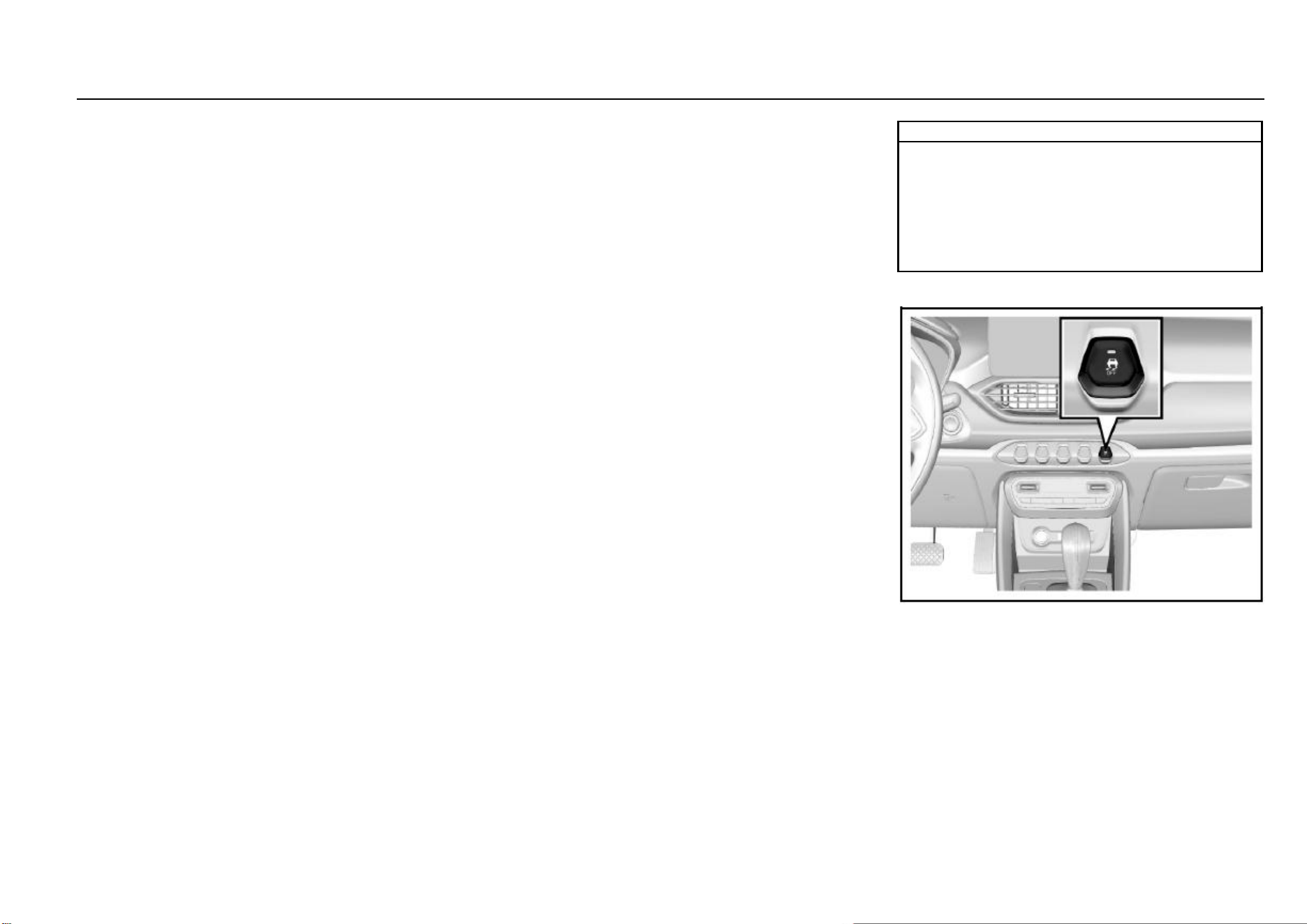
120 Driving and Controls
Electric Brake Force Distribution (EBD) System
The EBD system uses the high-speed computer to
respectively induce and calculate different ground to which
four wheels are attached, and thus calculate different friction
values at the moment the vehicle brakes. Therefore, four
wheels can be able to brake in different ways and force
based on different conditions, and can be adjusted fast
during movement, so as to ensure that the vehicle is stable
and safe.
Electronic Stability Control (ESC) System
The ESC system is a new-type active safety system,
representing the further development of the functions of
anti-lock brake system (ABS) and traction control system
(TCS). In addition, the yaw rate sensor, lateral acceleration
sensor and steering wheel turn angle sensor are added. The
driving force and braking force of front and rear, left and right
wheels are controlled through the ECU, which ensures the
lateral stability of the vehicle. When the driver operates the
vehicle beyond the limit values, in case of turning at high
speed, the ESC system automatically intervenes to ensure
that the vehicle returns to be controllable and ensure the
safety. Indicators relevant to the ESC system consist of ABS
MIL, EBD MIL, ESC MIL and ESC OFF indicator.
1. Indicators illuminate for self-check when the ignition
switch is connected. The 4 indicators are normally on
for 3s, indicating that the ESC system is conducting
self-check and indicators work normally. The 4
indicators go out 3s later under the normal condition.
When faults (such as neglected installation, loosened
connector, abnormal CAN communication) exist on
the ESC system, only the ESC OFF lamp will go out
3s later, and other 3 lamps are normally on.
2. In the process of driving the vehicle, if the ESC
function is activated, the ESC lamp will flicker, telling
the Owner that the ESC system is working. If the ESC
system functions abnormally but the ABS+EBD
system functions normally, the ESC lamp is normally
on, indicating that the ESC system gets faulted. If the
ESC system and the ABS function abnormally and the
EBD system functions normally, the ESC lamp and
the ABS lamp are normally on. If the ESC system, the
ABS and the EBD system function abnormally, the
ESC lamp, the ABS lamp and the EBD lamp are
normally on.
3. The ESC OFF lamp is used to indicate that the ESC
function is disabled (the lamp will be normally on so
long as the ESC function is disabled; the lamp will go
out if the function is enabled). If the Owner presses
the ESC OFF switch, some ESC functions will be
disabled, and the ESC OFF lamp illuminates. When
the switch is pressed, the ESC system is working, and
the ESC function will not be disabled immediately and
will be disabled after the work is over. If the Owner
presses the ESC switch again, all functions will be
enabled again. If the pressed time of ESC switch
exceeds 10s, the ESC system will consider it as one
incorrect operation (for example, the switch is pressed
by one unknown article incautiously), the ESC
function will not be disabled.
4. The ESC system will be activated automatically after
every re-ignition.
Note
The ESC system may not be able to help you escape
from out-of-control in the ultimate state for sure.
Therefore, take care during daily driving. You had
better disable the ESC system when crossing country
on a sandy and rocky pavement. As it is time for the
ESC system to function on an icy, snowy and slippery
pavement, the ESC system shall not be disabled.
ESC OFF Switch
Press the ESC OFF switch after starting the vehicle, and the
ESC OFF lamp on the instrument cluster illuminates and
some ESC functions are disabled. Press the ESC switch
again, the ESC function is enabled again and the ESC OFF
lamp on the instrument cluster goes out.
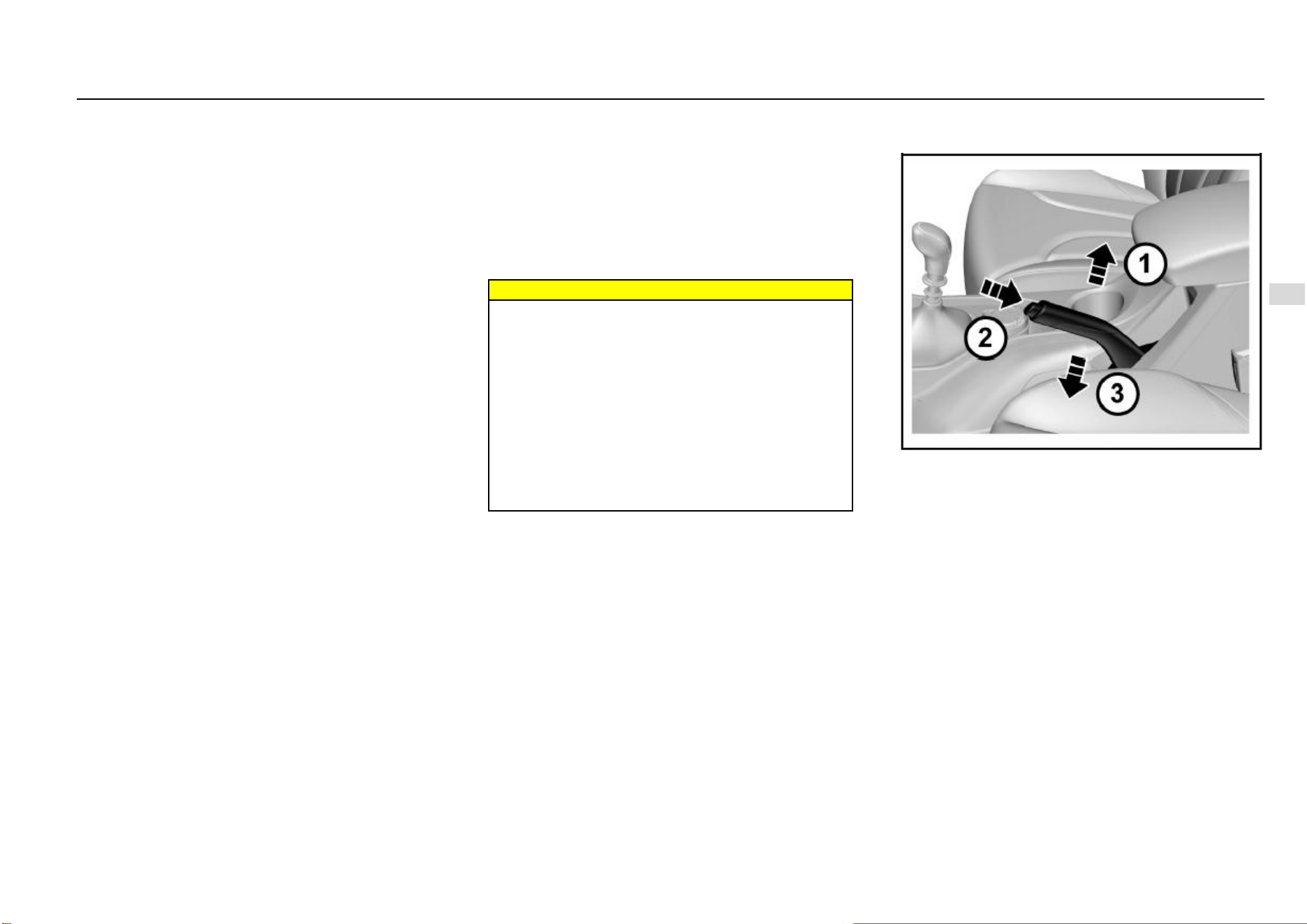
Driving and Controls 121
8
Driving and Controls
Normally, it is not recommended to disable the ESC system.
The system should be disabled temporarily only when the
vehicle gets out of the mire or the vehicle climbs on a
snowfield, etc.
Hill-start Hold Control (HHC) System *
The ESC system has the HHC function. The function can
help the vehicle to start easily on a slope without using the
parking brake.
Whether the driver is driving or reversing onto a hill, the start
assistant is provided through the function. Therefore,
engage gear before starting, please.
When the hill-start hold control functions, after the brake
pedal is released, the vehicle still keeps the braking force
for 1-2s. In this case, the vehicle will not slide backwards.
For one MT vehicle, the driver can focus on engagement of
accelerator and clutch in 2s, so as to deal with the tense hill-
start with ease.
In 2s, if the driving force applied by the driver is greater than
the resistance which the vehicle is subject to when running
onto a hill, the system will gradually reduce the braking force
and the vehicle starts running smoothly. If the vehicle fails
to start running in 2s, or the driving force applied by the
driver is insufficient, the pressure of the brake system is
released automatically and the vehicle may start sliding a
slope. At the time, you can depress the brake pedal to make
the vehicle come to a complete stop, and the system will still
help you to conduct the next start (when conditions are met).
Conditions for the HHC system to function:
1. No fault exists on the system, and the engine has
been operating;
2. The vehicle is motionless and the brake pedal has
been depressed;
3. The drive gear or reverse gear has been engaged;
4. The system detects that the gradient value is met. (In
theory, when the slope is > 4%, the vehicle will nod
during braking, and the nodding angle will offset the
slope. As a result, the system may fail to be started
on a ramp whose slope is > 4%.)
Warning
The HHC function may fail to prevent the vehicle from
sliding a slope on a very slippery or steep hillside.
Only as one driver-assistance measure, the HHC
function cannot supersede the parking brake function.
Always conduct the parking brake when getting out of
the vehicle. If there is no sufficient driving force
provided after the brake pedal is released, the vehicle
will slide backwards. At this time, please immediately
draw back the parking brake and depress the park
pedal.
If the engine flames out during the process, please
immediately draw back the parking brake and depress
the park pedal.
Parking Brake
Mechanical Hand Brake *
The parking brake impacts rear wheels.
The parking brake lever is between two front-row seats. If
you are to conduct the parking brake, you should stop the
vehicle, depress the brake pedal and tension the parking
brake lever.
When you are to release the parking brake, depress the
brake pedal and take following measures:
1. Draw back the parking brake lever slightly.
2. Press the button on the parking brake lever joint.
3. Release the parking brake lever when holding the
button pressed.
When parking on a downhill or uphill pavement, tension the
parking brake as tightly as possible.
122 Driving and Controls
When parking the vehicle on one uphill ramp, turn the
front wheels away from the road shoulder.
When parking the vehicle on one downhill ramp, turn
the front wheels towards the road shoulder.
Vehicle equipped with a manual transmission:
1. Turn the gearshift lever to the neutral gear when
parking the vehicle on the horizontal ground.
2. Turn the gearshift lever to the reverse (R) gear when
parking the vehicle towards the downhill direction.
3. Turn the gearshift lever to Gear 1 when parking the
vehicle
When parking one automatic model with dual clutch
transmission, engage Gear P on all pavements.
Caution
If the parking brake is not engaged correctly, the
vehicle may move automatically due to out-of-control
in some cases (such as in case of parking on a ramp)
and thus a danger may be caused. When necessary,
please have the Aftersales Service Center adjust.
Note
Do not drive the vehicle with the parking brake not
released; otherwise the rear wheel brake may get
overheated or be subject to premature wear. As a
result, you must replace the rear wheel brake;
otherwise, other components of the vehicle may get
damaged.
Electric Power Steering (EPS) System
The EPS system provides the steering assist for the vehicle.
The power steering fluid is not required for the system,
which brings great convenience for the daily vehicle
maintenance.
When the ignition switch is connected, the EPS MIL
illuminates momentarily. The EPS MIL does not go out or
illuminates when the vehicle is running, indicating the EPS
system is faulted. In case of such condition, you need
immediately go to Aftersales Service Center to check.
When the EPS system is under extreme conditions of high
load work for a long time (For example, the steering wheel
is “turned to the end” for a long time, or the vehicle is moved
into the garage at low speed repeatedly to a wide angle),
the thermal protection function may be activated due to
excessively high temperature of electrical elements.
The system will reduce the power assist after it enters the
thermal protection state, and at the time you have to steer
the wheel with great force. If the normal power assist need
be recovered, you can steer the wheel at a smaller angle or
promote the vehicle speed. You can restart the vehicle
when necessary.
Note
The EPS system will adjust the power assist according
to the vehicle speed. As a result, the steering wheel
can be turned easily at low speed and be turned
relatively steady at high speed.
Driving and Controls 123
8
Driving and Controls
Fuel
Fuel Suggestions
Fill GB 92# gasoline for vehicle or gasoline with the
equivalent standard No., or gasoline with a higher standard
No. Using the fuel with an extremely low octane value will
reduce power and torque of the engine, and increase the
consumed fuel volume.
Do not Use Methyl Alcohol
Do not use the fuel containing methyl alcohol on the vehicle.
This fuel will reduce the vehicle performance and damage
the fuel system components.
Driving in Other Countries
When driving your vehicle in other countries:
Please follow all registration and insurance
regulations.
Confirm that the country can provide proper fuel.
Caution
If you use any incorrect fuel, the engine and the
catalytic converter will get seriously damaged. Always
use the fuel suitable for your vehicle.
For the purpose of safety, the fuel tank, pump and pipe
must be grounded correctly. The static electricity will
ignite vapor included in the gasoline. You will get
burnt and the vehicle will get damaged.
Dangers
The fuel is one of flammables or explosives.
Smoking is prohibited. Keep away from open flames,
sparks and smoking materials. If gasoline catches fire,
serious burns will be caused and your vehicle will get
damaged.
If you smell fuel odors, please immediately ask
Aftersales Service Center to repair according to the
fault cause.
Caution
Using the fuel with an extremely low octane value will
lead to uncontrolled burning and cause the engine to
be damaged. Using the fuel containing methyl alcohol
is not allowed for the vehicle design. Therefore, do not
use the fuel containing methyl alcohol. As the methyl
alcohol will corrode the metal parts in the fuel system
and damage the plastic and rubber parts. The damage
caused due to use of the fuel containing methyl
alcohol does not belong to the warranty scope. If
contents of manganese and iron exceed the standard,
the three-way catalytic converter may be blocked, and
the spark plug misfires, etc. Therefore, please use the
gasoline meeting requirements of the national
standard.
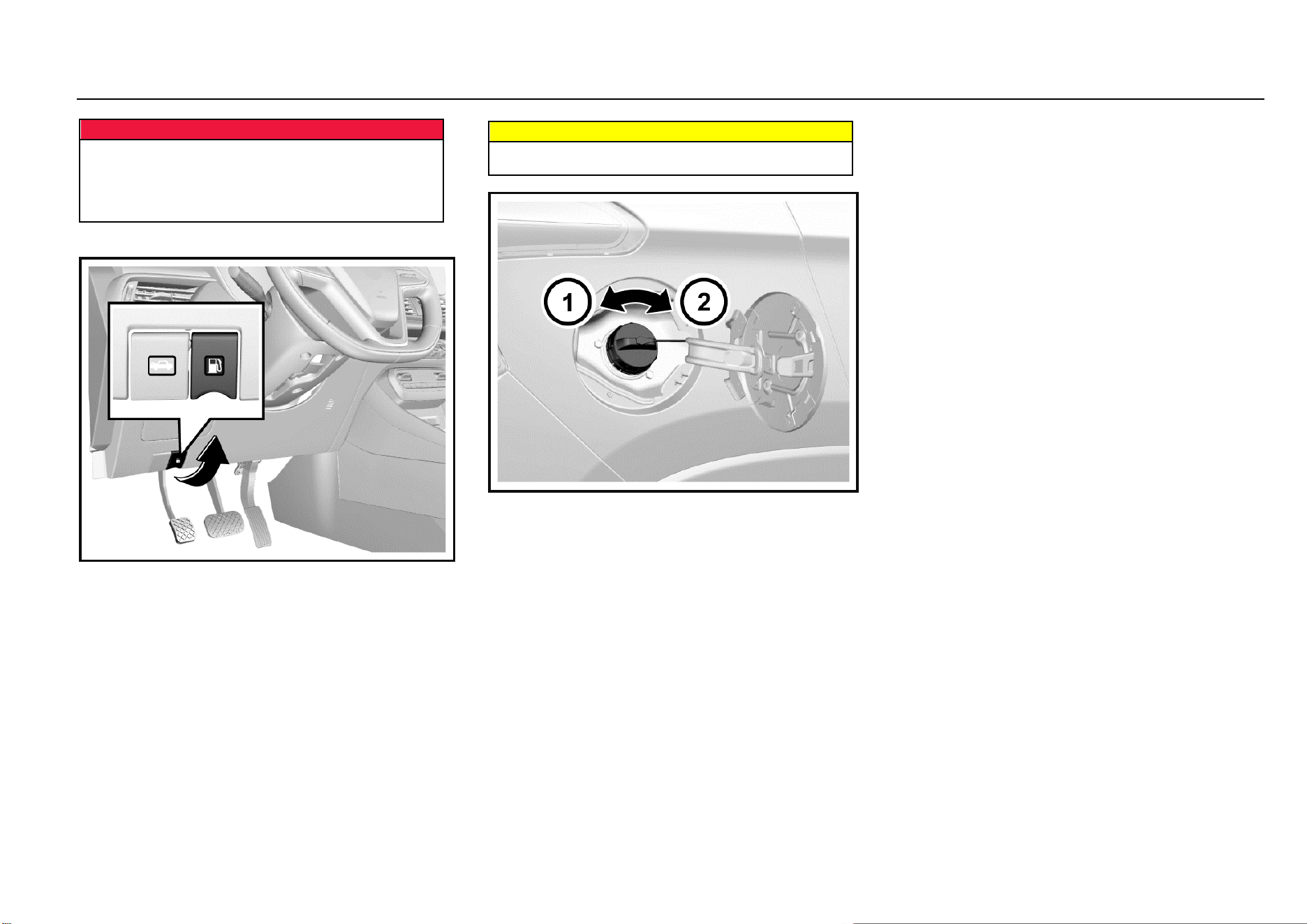
124 Driving and Controls
Dangers
Shut down the engine and any heating devices
provided outside the combustion chamber before
refueling. Turn off all mobile phones.
Follow operation and safety instructions of gasoline
station when refueling.
Fuel Filling
1. Stop the engine from running.
2. Pull up the filler flap release handle at the left lower
side of the instrument panel to open the filler flap.
Warning
If you fail to open the filler flap in the cold weather, you
can gently tap the filler flap. Then, try again.
3. Slowly turn the filler cap anticlockwise. If you hear the
hissing sound, wait till the sound stops, and then
unscrew the cap.
4. Unscrew the filler cap. The filler cap is connected to
the filler flap with the chain. Hang the chain to the
hanger on the filler flap to secure the filler cap.
5. Reinstall the filler cap after refueling. Turn the filler
cap clockwise till clicks are heard.
6. Tightly close the filler flap.

Driving and Controls 125
8
Driving and Controls
Vehicle Service & Maintenance
General Information ....................................................... 126
Accessories and Vehicle Retrofitting .................... 126
Vehicle Storage.................................................... 126
Driver Checklist ............................................................. 127
Exterior ................................................................ 127
Interior .................................................................. 127
Engine Compartment..................................................... 128
Engine Oil ...................................................................... 130
Engine Oil Level Check ........................................ 130
Engine Oil and Oil Filter Replacement ................. 130
Coolant .......................................................................... 131
Brake and Clutch Fluid .................................................. 132
Brake/Clutch Fluid Adding ................................... 132
Transmission Fluid ........................................................ 134
Transmission fluid leakage check ........................ 134
Windshield Washer Solvent ........................................... 134
Windshield Wiper .......................................................... 135
Air Filter ......................................................................... 135
Air Filter Cleaning ................................................ 135
Drive Belt ....................................................................... 136
Brake Pedal ................................................................... 136
Brake Pedal Travel Check ................................... 136
Fuse .............................................................................. 136
Indoor Fuse Box ................................................... 137
Engine Compartment Fuse Box ........................... 137
Indoor Fuse Box Layout ....................................... 138
Engine Compartment Fuse Box Layout ............... 139
Lamp Bulb Replacement ............................................... 140
Bulb Specifications ............................................... 141
Wheels and Tires .......................................................... 147
Maintenance ........................................................ 147
Internal Tread Wear Indicator .............................. 148
Tire Rotation ........................................................ 148
Winter Tire ........................................................... 149
Tire Chain ............................................................ 149
Spare Tire, Jack and Tools ............................................ 149
Tool Kit ................................................................. 149
Spare Tire ............................................................ 150
Jack Lifting Point .................................................. 151
Tire Replacement ................................................. 152
Jump Start (Dead Battery) ............................................. 154
Vehicle Traction ............................................................. 155
Emergency Trailer ................................................ 156
Getting Vehicle out of Trap ............................................ 158
Vehicle Maintenance...................................................... 158
Cleaning Agent ..................................................... 158
Vehicle Interior Maintenance and Cleaning .......... 159
Glass Surface ....................................................... 159
Vehicle Exterior Maintenance and Cleaning ......... 160
Corrosion Prevention ............................................ 160

126 Vehicle Service & Maintenance
General Information
Accessories and Vehicle Retrofitting
We recommend using original spare and accessory parts
and parts and components that are approved by the
company to be particularly suitable for the vehicle. We may
not able to guarantee the compatibility of other products with
this vehicle, even if these products meet the specified
requirements or are otherwise approved.
For parts of environmental protection, including the engine,
transmission, coating, fuel evaporation control device,
crankcase emission control device, OBD, ECU, catalytic
converter, muffler, EGR (if any), supercharger (if any) and
intercooler (if any), it is preferable to use original spare and
accessory parts. Otherwise, vehicle emissions may not
meet the standard.
The Company is not responsible for any problem caused by
the use of non-original parts and components (including but
not limited to the non-compliance of environmental
emissions due to the use of non-original parts and
components or other violations of laws and regulations).
Without the approval of SGMW, do not retrofit the electrical
system.
Tips for Glass Filming
During the process of glass filming, the cleaning solution
may easily enter electronic components around the
instrument panel, causing electrical faults. Please complete
waterproofing work before filming.
Caution
Do not retrofit the vehicle. Otherwise, the
performance, durability and safety of the vehicle may
be affected; problems caused by retrofitting are not
within the scope of warranty.
Vehicle Storage
Long-term Storage
Several months of storage of the vehicle:
Clean the vehicle for waxing.
Check the wax coating of engine compartment and
the underbody.
Clean and protect the rubber seal.
Replace the engine oil.
Drain the washer fluid reservoir.
Check coolant antifreezing agent and corrosion
protection.
Adjust the tire pressure according to the specified
value under full load.
Park the vehicle in a dry and well-ventilated area. Shift
to Gear 1 or reverse gear to prevent the vehicle from
sliding.
Close all doors and lock the vehicle.
Disconnect the clip from the vehicle battery negative
terminal. Pay attention to that all systems are out of
service at this time, e.g. theft deterrent system.
Vehicle being Put into Operation again:
Connect the clip to the vehicle battery negative
terminal. Enable the electronic device of power
window.
Check the tire pressure.
Fill the washer fluid reservoir.
Check the engine oil level.
Check the coolant level.

Driving and Controls 127
8
Driving and Controls
Driver Checklist
Check the interior, exterior and engine compartment
regularly to keep the vehicle safe and reliable.
Exterior
Tire
Inflate tires correctly. (Refer to “Wheels and Tires” in
this chapter).
There is no crack on tire wall or tire tread.
There is no foreign matter in tread pattern.
Lamp
It includes all driving lamps, headlamps, tail lamps,
turn signal lamps, brake lamps and fog lamps.
Oil Tank
Check whether the level of fluid containers under
engine hood is appropriate.
Windshield Wiper
Check the state of wiper arms and blades.
Interior
Steering
Check whether the steering wheel is too loose (free
travel).
Parking Brake
Ensure the travel of parking brake lever is
appropriate.
Instrument Panel
Check whether all instruments, control buttons and
warning lamps are functioning normally.
Rearview Mirror
Ensure the reflecting surface of rearview mirror is in
good state and clean.
Check whether all rearview mirrors can be readjusted.
Control
Check the brake pedal and clutch pedal for
appropriate travel.
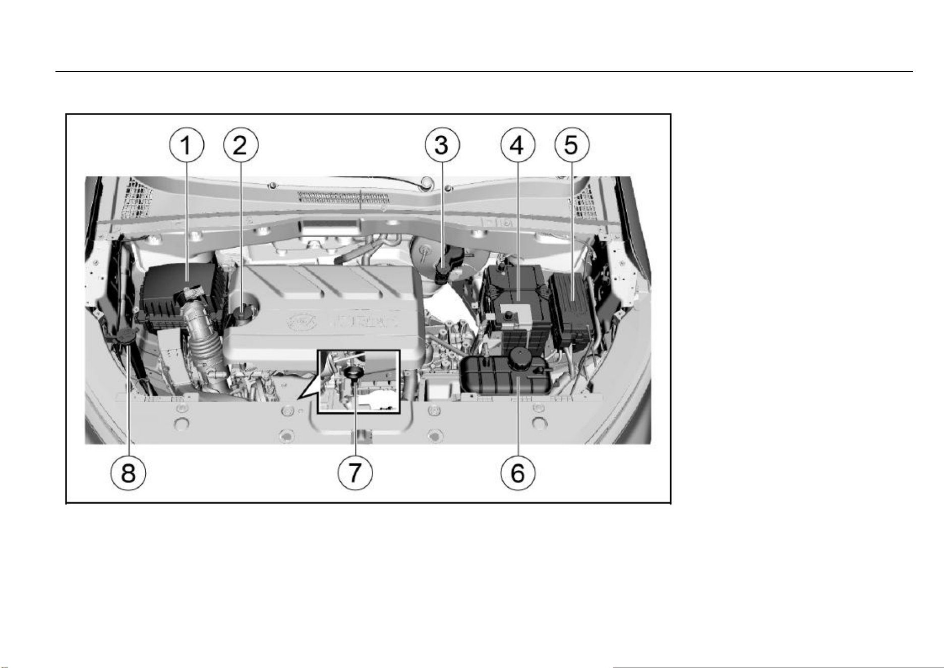
128 Vehicle Service & Maintenance
Engine Compartment
1.5T Engine
1. Air filter
2. Engine oil filler cap
3. Brake/clutch fluid reservoir
4. Battery
5. Fuse and relay box
6. Coolant pot
7. Engine oil dipstick
8. Windshield washer solvent container

Driving and Controls 129
8
Driving and Controls
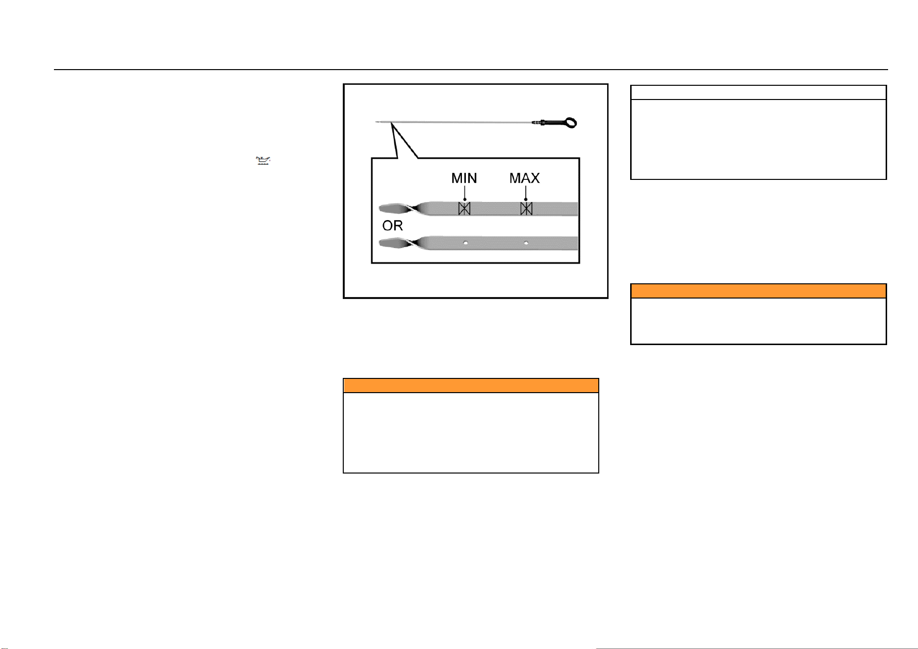
130 Vehicle Service & Maintenance
Engine Oil
Maintain the engine oil at a proper level to ensure correct
lubrication of engine.
It is normal that the engine consumes some oil.
Check the engine oil level regularly, e.g. every time parking
for refueling.
If the engine oil pressure warning lamp “ ” on the
instrument panel is on, check the engine oil level
immediately.
Engine Oil Level Check
1. Park the vehicle on a horizontal ground.
2. After the engine stops running, wait for a few minutes
to have the oil back to the oil pan. For cold engine, the
time for the oil returning to the oil pan will be relatively
long.
3. Pull out the oil dipstick and clean it.
4. Insert the oil dipstick completely.
5. Pull out the oil dipstick again.
6. Check the engine oil on the dipstick to ensure that the
oil is free of contamination.
7. Observe the oil level via the oil dipstick. The oil level
should be between the lower limit and the upper limit.
8. If the oil level is lower than the lower limit, add engine
oil of the same grade to have the oil level approaching
to but not higher than the upper limit. The engine oil
filler cap is on the cylinder head cover. Refer to the
diagram of “Engine Compartment”.
Caution
Engine oil is irritating and can cause illness or fatal
danger in case of swallowing.
● Keep it out of reach of children.
● Avoid repeated or prolonged skin contact with
engine oil.
● Wash the part in contact with engine oil with
soap water or hand sanitizer.
Note
Prohibit the engine oil level from being higher than the
upper limit mark on the oil dipstick. Excessive engine
oil may have adverse effect on the engine, including:
● Increased engine oil consumption.
● Oil spilling of spark plug.
● A large amount of carbon deposits accumulated
on the engine.
Engine Oil and Oil Filter Replacement
The engine oil will lose the lubricating capacity after being
contaminated. Be sure to replace the engine oil in
accordance with maintenance procedures. The oil filter
must be replaced at the same time of engine oil replacement
every time. Under harsh conditions, the replacement
interval of engine oil and oil filter must be shorter than the
interval specified in standard maintenance procedures.
Caution
This work requires professional skills, tools and
equipment; therefore, please go to the Aftersales
Service Center for help. Otherwise, it may cause
personal injury or damage to the vehicle.
Harsh conditions include but not limited to:
Frequent cold start.
Frequent starting and stopping in case of traffic jam.
Frequent driving for short trips.
Driving and Controls 131
8
Driving and Controls
Frequent driving at an outside temperature of below 0
°C.
Long time idling.
Frequent driving at low speed.
Frequent driving under dusty conditions.
Caution
The engine oil and oil drum are harmful to human
health.
Avoid repeated or prolonged exposure to engine oil. In
case of contact with engine oil, wash the skin with
soap water or hand sanitizer. Keep this kind of toxic
substance out of reach of children.
Engine oil is irritating to the skin and can cause illness
or fatal danger in case of swallowing.
Note
It is prohibited to dispose of old engine oil and filters
together with household garbage.
It shall make use of local legal waste management
facilities.
Old engine oil and filters contain harmful substances
that are harmful to human health and threaten the
environment.
Note
The use of non-specified or poor quality engine oil or
additives will cause damage to the engine. Please
consult the Aftersales Service Center before
attempting to use additives.
Coolant
The vehicle cooling system is filled with ethylene glycol
coolant.
This kind of coolant in right mixing ratio can provide
excellent anti-corrosion and antifreezing performance for
the cooling and heating systems.
When the engine is in a cold state, the coolant level shall be
between MIN (minimum) and MAX (maximum) marked on
the coolant tank. The coolant level rises with the engine
temperature rise and drops as the engine cools.
If the coolant level is lower than the MIN (minimum) mark,
please go to the Aftersales Service Center for coolant filling
or replacement.
Note
Ordinary water or coolant in wrong mixing ratio will
cause damage to the cooling system.
It is prohibited to use ordinary water, alcohol or
methanol on the vehicle to prevent freezing.
Caution
Under pressure, hot coolant and steam may spray out,
causing serious personal injury.
It is prohibited to open the coolant tank cover before
the engine and radiator cool down.
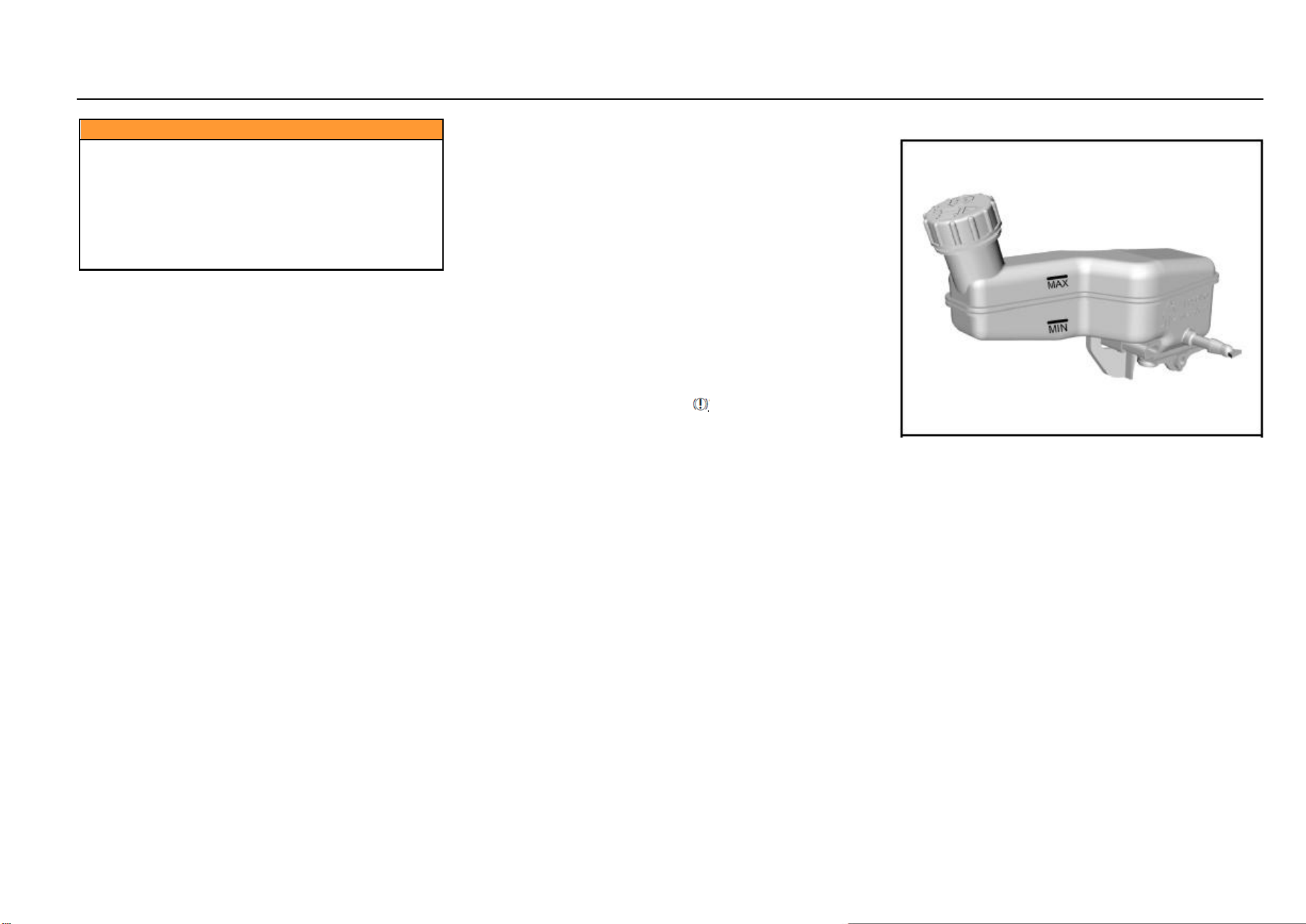
132 Vehicle Service & Maintenance
Caution
The coolant is a dangerous substance.
● Avoid repeated or prolonged exposure to
coolant.
● In case of contact with coolant, wash the skin
and fingernail with soap water.
● Keep it out of reach of children.
● Coolant is irritating to the skin and can cause
illness or fatal danger in case of swallowing.
Brake and Clutch Fluid
There is a brake and clutch fluid reservoir on the vehicle.
The brake and clutch fluid is moisture-absorbing, and the
fluid with excessive water content will reduce the efficiency
of the hydraulic brake/clutch system. Replace the fluid as
per the instruction in the Manual to avoid corrosion of the
hydraulic system.
Be sure to use the brake/clutch fluid recommended by
SGMW. Add fluid into the reservoir to reach a proper level.
The fluid level shall not be lower than the MIN (minimum)
mark or higher than the MAX (maximum) mark.
The cause of excessive low brake fluid level may be leakage
of brake system or normal wear of brake pad/lining. Please
contact the Aftersales Service Center to ensure that
whether the system needs to be repaired. If repairs are
necessary, add fluid after repair of hydraulic braking system.
When the brake fluid level is lower than the lower limit, the
braking system warning lamp “ ” will be on. Refer to
“Braking System Warning Lamp” in Chapter “Instrument and
Control Device”.
Brake/Clutch Fluid Adding
1. Thoroughly wipe off the dirt around the reservoir filler
cap.
2. Open the filler cap.
3. Add the brake/clutch fluid recommended by SGMW to
reach the MAX (maximum) mark. Be careful not to
spill the fluid on the paint surface. In case of spilling
on the paint surface, wash the area with cold water
immediately.
4. Re-install the reservoir filler cap.
Driving and Controls 133
8
Driving and Controls
Note
Before opening the filler cap, clean the area around the
brake/clutch fluid reservoir filler cap.
Contamination of the brake/clutch fluid system will
affect the system performance, resulting in costly
repairs.
Caution
The brake/clutch fluid is irritating to the skin and eyes.
Keep the skin or eyes from contact with the
brake/clutch fluid. In case of contact, wash the part in
contact with the brake/clutch fluid with soap water or
hand sanitizer thoroughly.
Caution
It is prohibited to dispose of the old brake/clutch fluid
as household garbage. It shall make use of local legal
waste management organization.
The old brake/clutch fluid and containers are
dangerous and may be harmful to human health and
the environment.
Caution
The brake/clutch fluid spilling over the engine may
cause a fire.
An overfull fluid reservoir is not allowed.
Engine fire may cause personal injury and damage the
vehicle and other properties.
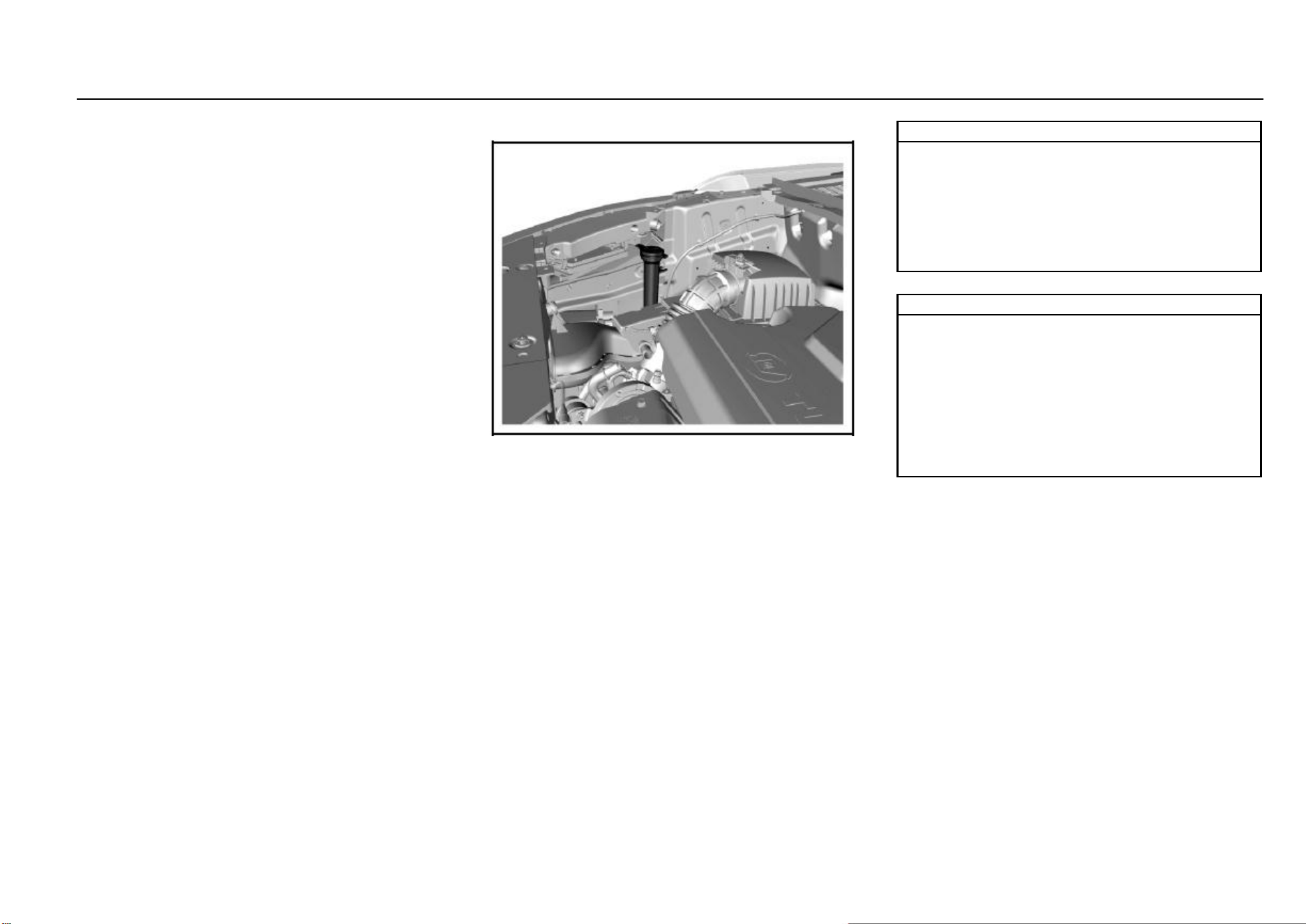
134 Vehicle Service & Maintenance
Transmission Fluid
Transmission fluid leakage check
This work requires professional skills and equipment. To
avoid personal injury or vehicle damage, it is suggested to
go to the Aftersales Service Center for help.
Windshield Washer Solvent
Before driving, be sure that the fluid reservoir contains
sufficient specified washer solvent.
In cold weather, the windshield washer solvent container
cannot be overfilled.
Washer solvent will swell under low temperature due to
freezing. An overfull container has no enough space for
expansion, thus resulting in damages.
Note
Please go to the Aftersales Service Center for filling of
the correct washer solvent.
Do not fill water or radiator antifreezing agent into the
windshield washer solvent container. The water will
lead the solution to freeze, and the frozen solution will
damage the windshield washing system. The radiator
antifreezing agent will damage the windshield washing
system and vehicle paint.
Note
Add windshield washer solvent:
It is suggested to use the ready-to-use special washer
solvent. If concentrated washer solvent is used,
please add water to dilute it according to the
manufacturer’s instructions.
Do not use tap water. Minerals or impurities contained
in tap water may block lines of the windshield washer.
If the temperature is likely to fall below freezing point,
use windshield washer solvent with good antifreezing
performance.
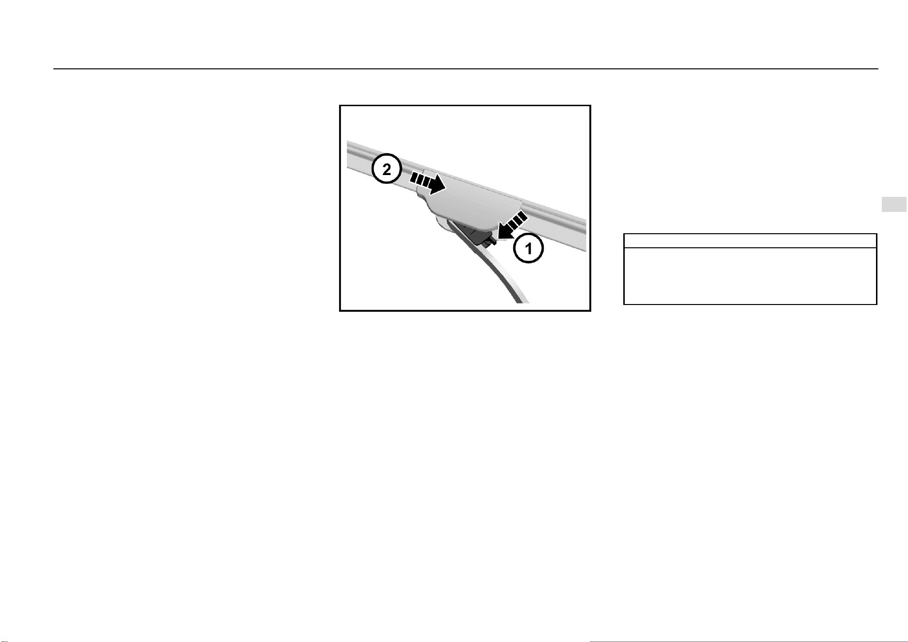
Driving and Controls 135
8
Driving and Controls
Windshield Wiper
Foreign objects on the windshield and blade will reduce the
effectiveness of the wiper. If the blade does not work
properly, wipe the windshield and the blade with special or
neutral washer solvent. Flush with water thoroughly. If
necessary, repeat the above operation. Do not wipe the
windshield with corrosive substances or materials that
cannot be removed from the glass (e.g. silicone).
The strips have a layer of graphite on the surface for
lubrication and protection. It should be protected from
excessive wiping and undue polishing.
Do not start the wiper when the windshield surface is dry.
Park the vehicle in a cool place as far as possible to prevent
exposure to high-temperature, which will accelerate the
aging and deformation of strips.
Remove foreign matters such as bird droppings, dust and
leaves from the windshield surface before starting the wiper;
otherwise, the service life of strips will be reduced.
Notes on Front Wiper Blade Replacement:
The front wiper is of semi-concealed design. Before
replacing the blade, operate the wiper to the maintenance
position and then fold the wiper arm. Otherwise, the right
wiper arm will contact the engine hood and damage the
paint when being folded.
Method: Turn the ignition switch to ON position and then to
LOCK position. Raise the wiper lever towards the steering
wheel and release it (single-point contact) within 30s, and
the wiper arm will swing to the maintenance position. After
replacing the blade, lower the wiper arm and turn the ignition
switch to ON position, and then the wiper will return to the
original position.
Wiper Blade Removal and Installation
Fold the wiper arm on the windshield for operation.
As shown in the figure, firstly press the release switch of the
wiper blade in the direction of arrow 1. Then hold the joint
part between the wiper blade and the wiper arm with the
other hand. Pull the wiper blade down slightly in the
direction of arrow 2 to separate the wiper blade from the
wiper arm.
During installation, insert and clamp the new wiper blade
into the U-slot of the wiper arm.
During the rear wiper blade removal, pull out the wiper blade
from the installation point on wiper arm. For installation,
align the blade with the installation point and press it into the
point.
Air Filter
Check and replace the air filter element regularly according
to the maintenance instructions in the Manual.
Air Filter Cleaning
If the air filter element is too dirty, clean it according to the
following procedures:
1. Shake the air filter element to remove floating dust.
2. Clean the interior of air filter housing.
3. Cover the filter housing with a wet cloth when cleaning
the filter element.
4. Clean the filter element with compressed air in the
opposite direction of the engine intake.
Note
Clean air is necessary for the normal operation of
engine.
It is prohibited to drive the vehicle without the air filter
element being installed. Otherwise, the engine will be
damaged.
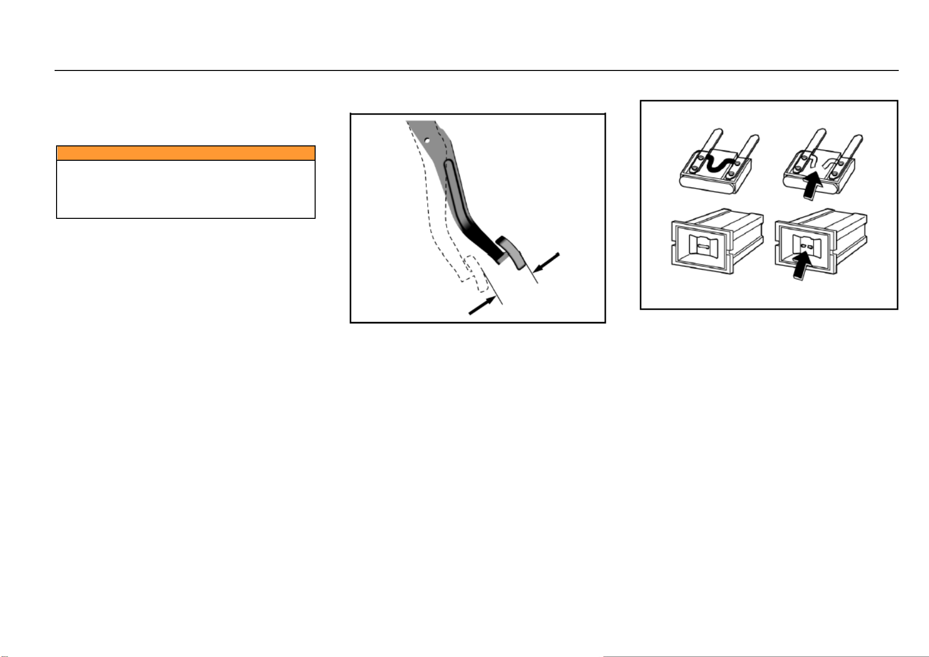
136 Vehicle Service & Maintenance
Drive Belt
For normal operation of engine and air compressor, the
drive belt should be adjusted to a good state. In case of
damage, break or wear, please replace the drive belt.
Caution
If the key is not pulled out, the engine may be start
unintentionally during check. Do not leave the key in
the ignition switch when checking the drive belt.
Sudden running parts may cause serious personal
injury when the engine is in operation.
Brake Pedal
Brake Pedal Travel Check
Brake pedal travel:
To avoid affecting the pedal travel, do not lay a thick carpet
in the brake pedal area.
The reasonable range of brake pedal free travel is 0~30
mm.
If the brake pedal fails to return or the brake pedal travel
becomes longer, please go to the Aftersales Service Center
for inspection. This may indicate faults of the brake system.
Fuse
Fuse replacement:
1. Open the fuse box cover.
2. Identify damaged fuses by finding out blown fuses.
3. Use a fuse extractor to remove the blown fuses. The
fuse extractor is in the engine compartment fuse box.
4. Figure out the cause of fusing and remove the fault.
5. Install new fuses with rated current meeting the
requirements.
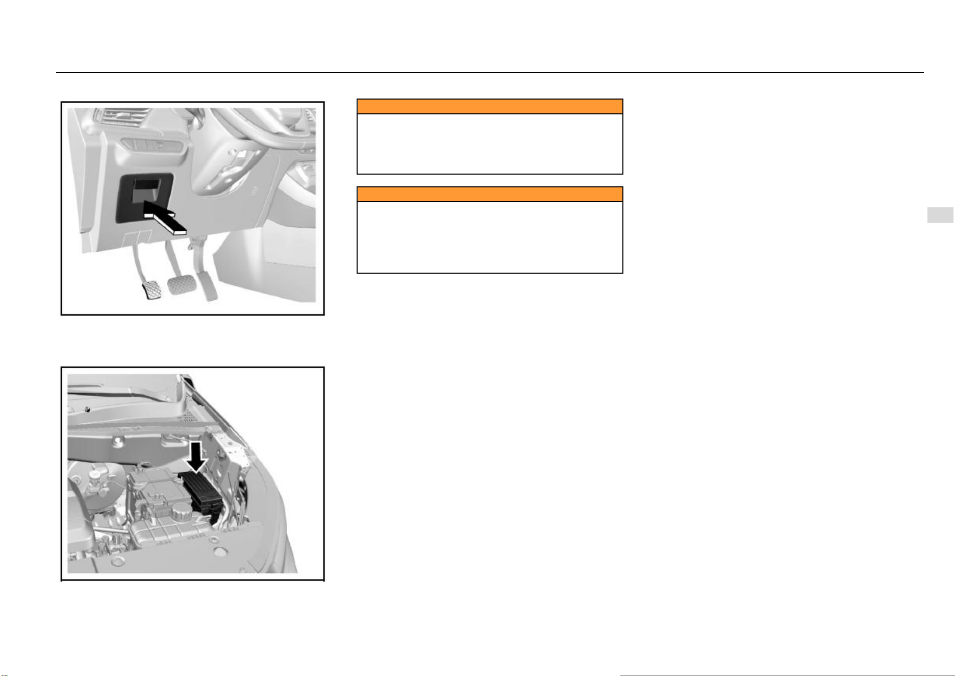
Driving and Controls 137
8
Driving and Controls
Indoor Fuse Box
The indoor fuse box is on the lower left side of the
instrument panel and it can be seen after pulling out the
storage box.
Engine Compartment Fuse Box
The engine compartment fuse box is next to the battery.
Caution
Do not use a conductive tool to remove the blown fuse.
The fuse extractor must be used. The use of metal and
other electric conductors may cause a short circuit,
damage the electrical system or cause a fire, resulting
in serious personal injury.
Caution
The use of fuse substitutes or the fuse with an
incorrect type and current rating may damage the
electrical system or cause a fire. Be sure to use a fuse
of the type and current rating that meets the
requirements. Otherwise, it may cause personal injury
and damage the vehicle and other properties.
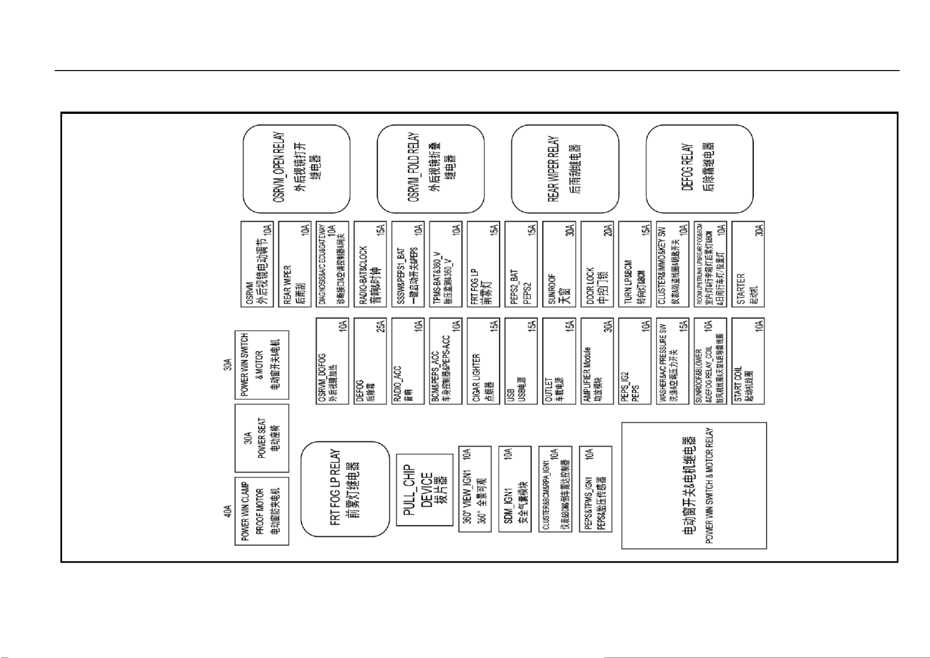
138 Vehicle Service & Maintenance
Indoor Fuse Box Layout
For vehicles with different models or configurations, the layout of fuse box internal components may be different. The owner’s actual vehicle shall prevail.
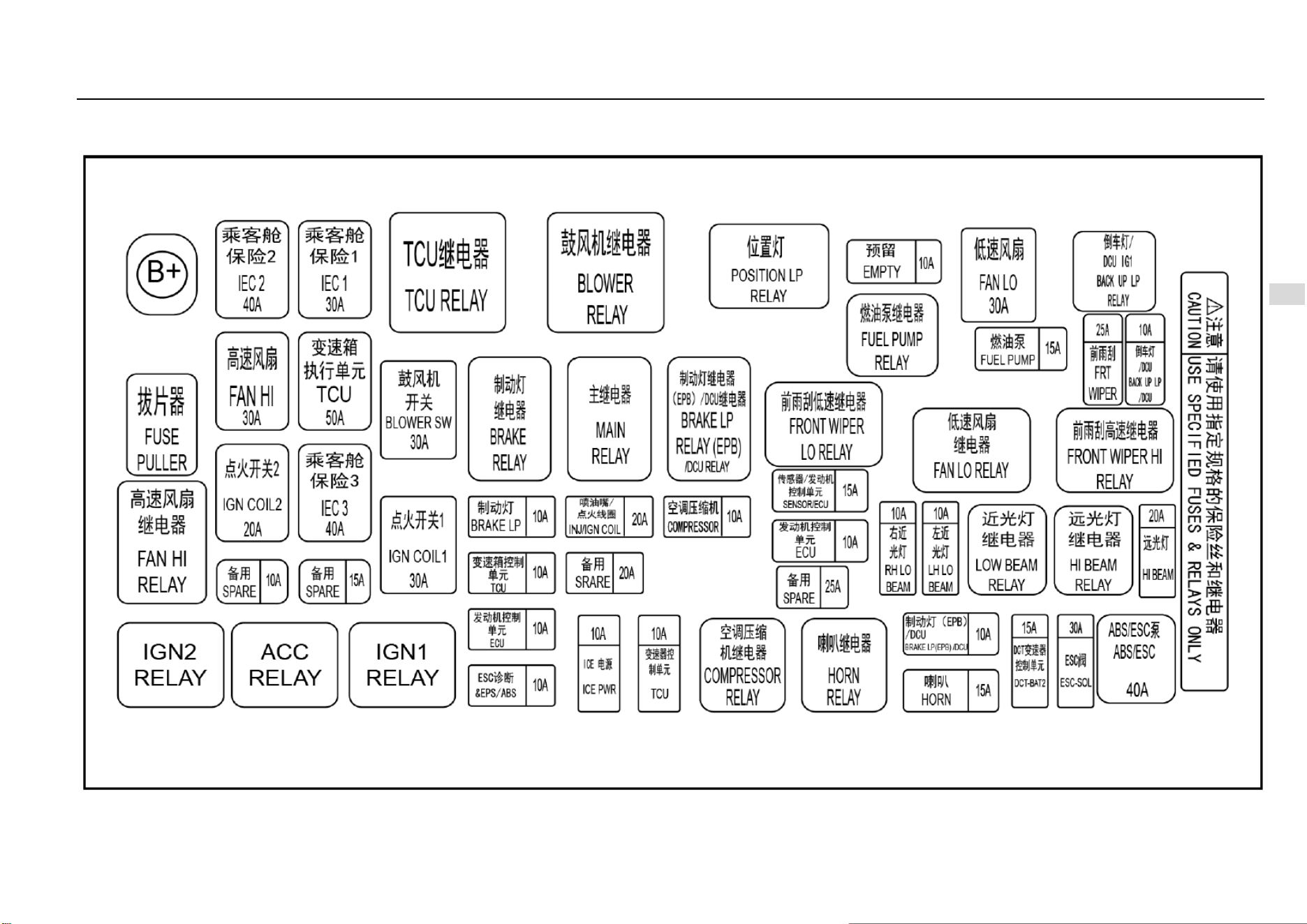
Driving and Controls 139
8
Driving and Controls
Engine Compartment Fuse Box Layout
For vehicles with different models or configurations, the layout of fuse box internal components may be different. The owner’s actual vehicle shall prevail.
140 Vehicle Service & Maintenance
Lamp Bulb Replacement
Caution
The gas in the halogen bulb is under pressure. Handle
with care and properly dispose of halogen bulbs.
● Wear safety glasses when removing or installing
the lamp.
● Take care to prevent bulbs from wear and
scratches.
● When the lamp lights up without being
packaged, prevent the bulb from contacting liquids.
● Light up the lamp for test after the bulb being
installed.
● Replace the cracked or damaged headlamp in
time.
● Do not touch the glass portion with ungloved
fingers when replacing the halogen bulb.
● Keep the bulb out of reach of children.
● Dispose of the old bulb carefully to prevent
personal injury due to bulb explosion.
Caution
Clean the halogen bulb with alcohol or mineral spirits
and non-woven fabrics. Do not touch the bulb with
hands directly.
Fingerprints may significantly shorten the effective
service life of halogen bulbs.
Caution
Professional skills and special equipment are required
for replacement of bulbs. It is suggested to go to the
Aftersales Service Center for help. Otherwise, it may
cause personal injury or damage the vehicle.
Lamp Fogging
When the temperature is low or the air is humid, there may
be water mist inside the lamp. Turn on the lamp, and the
water mist will dissipate after a while. If it is resulted from
the weather, repair is not necessary.
If the water mist does not dissipate after the lamp is turned
on and there is more and more water vapor, please contact
the Aftersales Service Center for inspection.
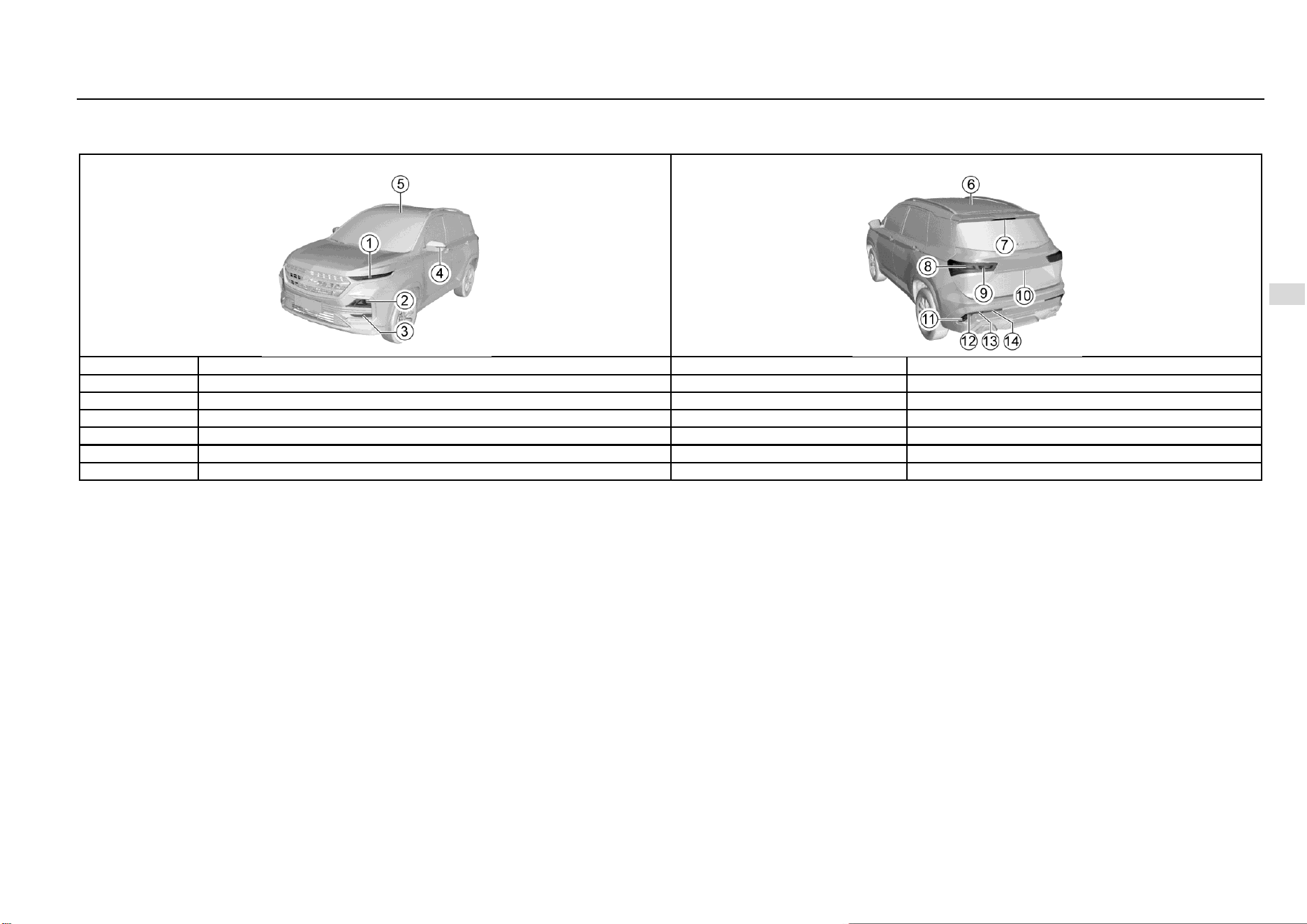
Driving and Controls 141
8
Driving and Controls
Bulb Specifications
High-end Configuration Model
S/N
Lamp bulb
Power x quantity
Remarks
1
Front turn signal lamp/front position lamp/daytime running lamp
LED
2
Low-beam lamp/high-beam lamp
LED
3
Front fog lamp
55W×2
H7
4
Side turn signal lamp
LED
5
Front Reading Lamp
LED
6
Rear Reading Lamp
LED
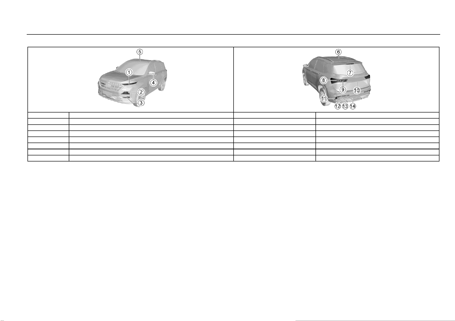
142 Vehicle Service & Maintenance
High-end Configuration Model (Continued)
S/N
Lamp bulb
Power x quantity
Remarks
7
High mount stop lamp
LED
8
Rear brake lamp/position lamp
21W/5W×2
P21W/W5W
9
Rear turn signal lamp
LED
10
Rear license plate lamp
LED
11
Rear turn signal lamp
LED
12
Backup Lamp
16W×2
W16W
13
Rear Fog Lamp
21W×2
P21W
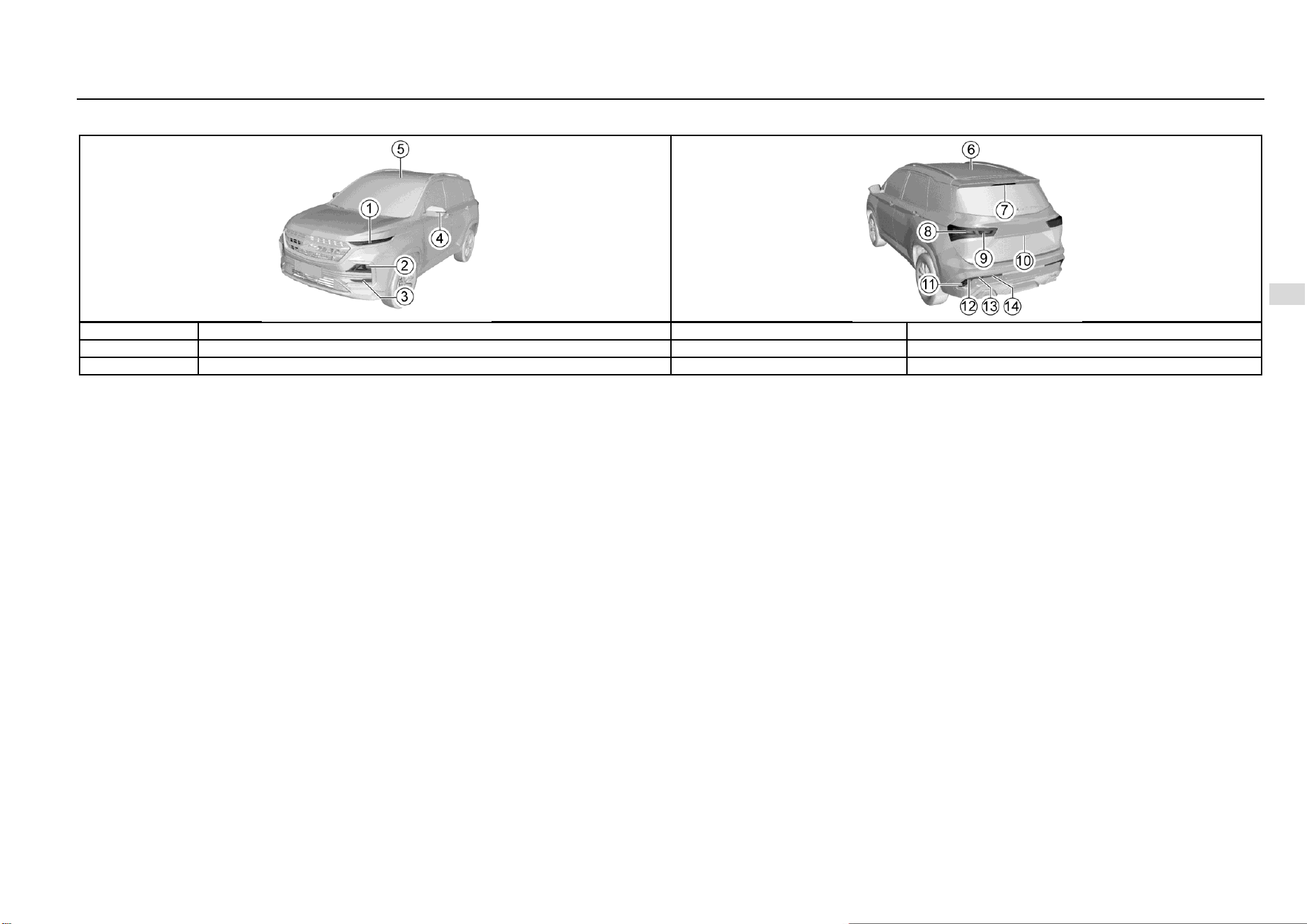
Driving and Controls 143
8
Driving and Controls
High-end Configuration Model (Continued)
S/N
Lamp bulb
Power x quantity
Remarks
14
Rear position lamp
5W×2
W5W
15
Luggage compartment lamp
LED
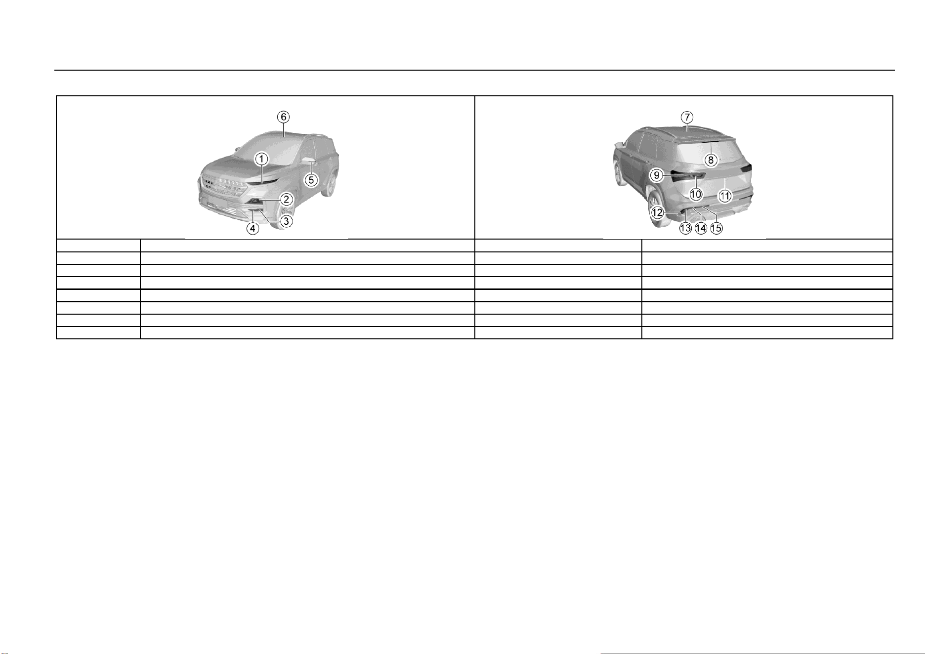
144 Vehicle Service & Maintenance
Low-end Configuration Model
S/N
Lamp bulb
Power x quantity
Remarks
1
Trim
Non-luminance
2
Low-beam lamp/high-beam lamp
60W×2
HB3
3
Front turn signal lamp
21W×2
PY21W
4
Front position lamp
5W×2
W5W
5
Side turn signal lamp
LED
6
Front Reading Lamp
5W×1
C5W
7
Rear Reading Lamp
5W×1
C5W
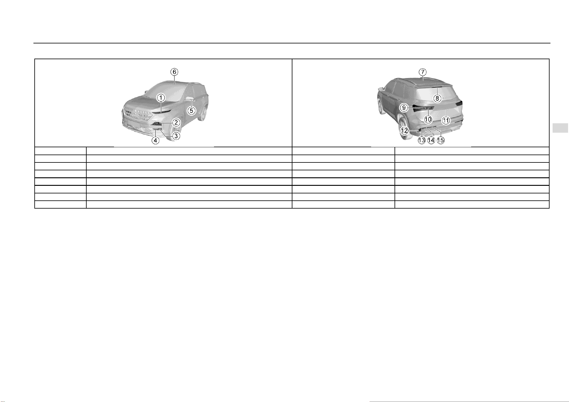
Driving and Controls 145
8
Driving and Controls
Low-end Configuration Model (Continued)
S/N
Lamp bulb
Power x quantity
Remarks
8
High mount stop lamp
LED
9
Rear brake lamp/position lamp
21W/5W×2
P21W/W5W
10
Rear turn signal lamp
LED
11
Rear license plate lamp
LED
12
Rear turn signal lamp
LED
13
Backup Lamp
16W×2
W16W
14
Rear Fog Lamp
21W×2
P21W
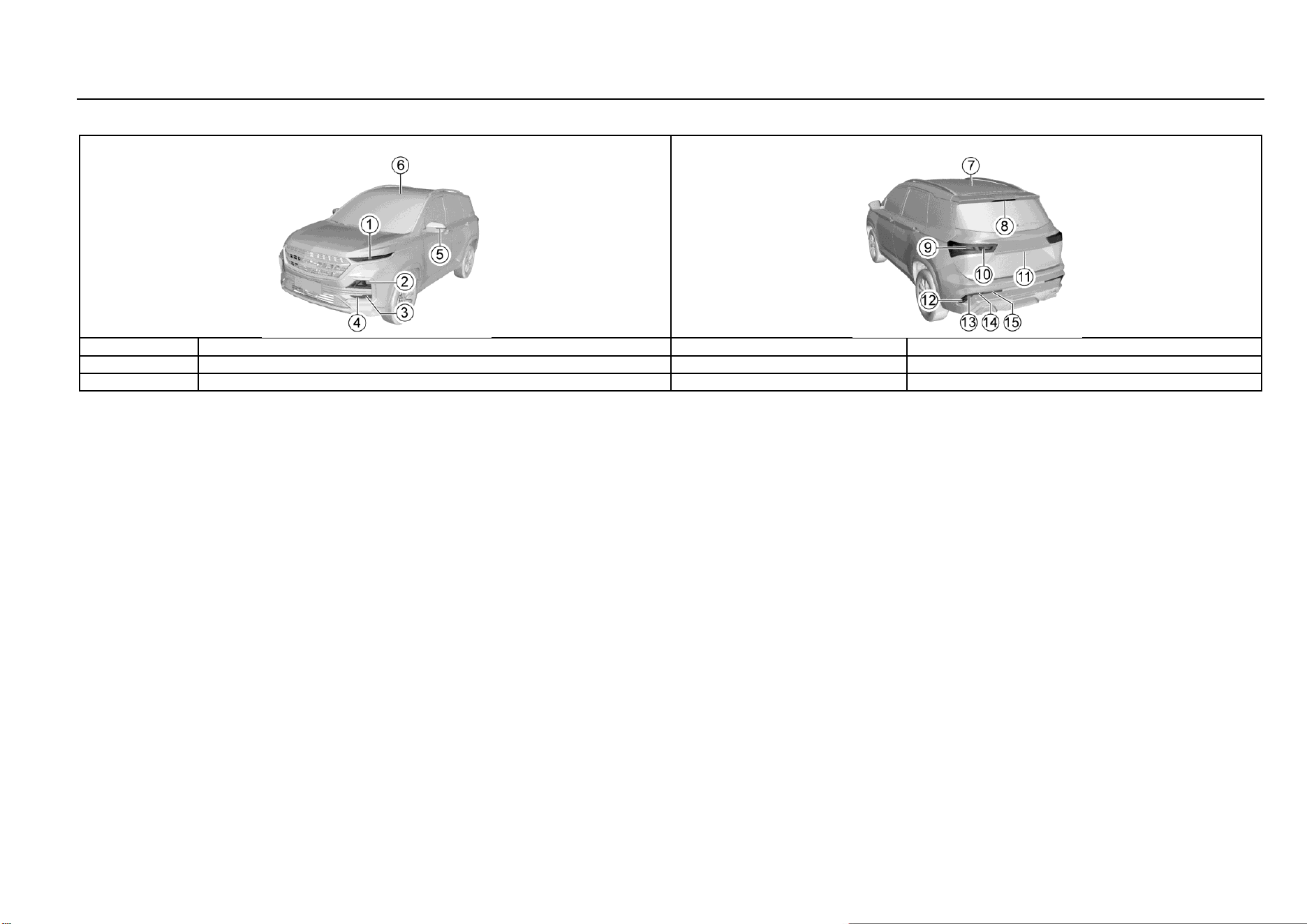
146 Vehicle Service & Maintenance
Low-end Configuration Model (Continued)
S/N
Lamp bulb
Power x quantity
Remarks
15
Rear position lamp
5W×2
W5W
16
Luggage compartment lamp
LED
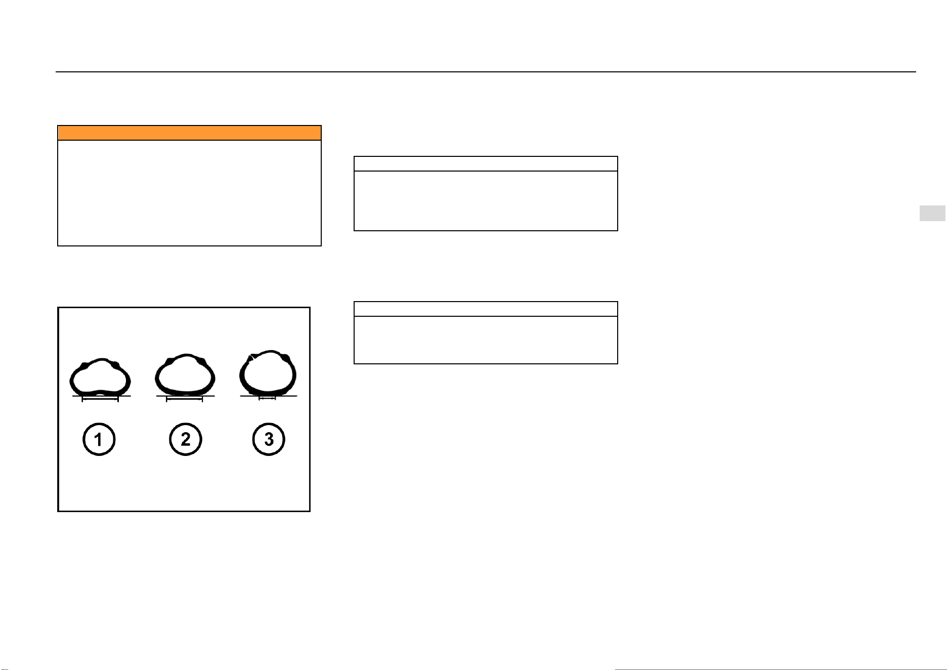
Driving and Controls 147
8
Driving and Controls
Wheels and Tires
Original tires guarantee optimum matching of riding comfort,
tread life and performance.
Caution
Be sure to use wheels and tires of specified
specifications. The use of wheels and/or tires of other
specifications may result in abnormal operation of
ABS and other relevant components and even cause
collision accidents.
Please consult the Aftersales Service Center before
replacing original tires or wheels.
Otherwise, it may cause personal injury and damage
the vehicle or other properties.
Maintenance
The tire pressure shall meet provisions of the Manual so as
to ensure optimum matching of driving comfort, safety and
driveability.
Refer to the tire load information label for the correct tire
pressure. The label is on the sill plate below the driver's
door.
At the time of cold start, check the tire pressure with an
accurate tire pressure gauge. After check of tire pressure,
tighten the valve core cap.
Note
Make sure to check the tire pressure at the time of cold
start. The reading measured after the tire temperature
has increased shall not prevail. Tires will become hot
after traveling for 1.6 Km and will not cool down
completely within 3h after stopping.
Check the tire pressure each time when refueling or at least
every month. Incorrect tire pressure may:
Increase tire wear.
Affect the vehicle manoeuvrability and safety.
Affect the riding comfort.
Reduce the fuel economy.
Note
● Vehicle overload is prohibited.
● Be sure to keep a proper tire inflation pressure.
● Be sure to check the tire inflation pressure at the
time of cold start (ambient temperature).
Excessively low tire pressure will cause overheat of the tire,
leading to internal damage and layered tread and even tire
burst when driving at a high speed. Even if the tire pressure
was restored later, driving under too low pressure may have
damaged the tire.
Tire and Wheel Maintenance
Running over sharp objects may damage tires and wheels.
If you have to run over these objects, please slow down.
Do not touch the curb when parking.
Regular Tire Check
Appearance damage.
Foreign material.
Piercing.
Cut.
Crack.
Protruding on side wall.
It shall also inspect the wheel for damage.
Tire defects including the above defects may lead to vehicle
out of control, causing personal injury.
In case of damage or abnormal wear of tire or wheel, please
consult the Aftersales Service Center for help.
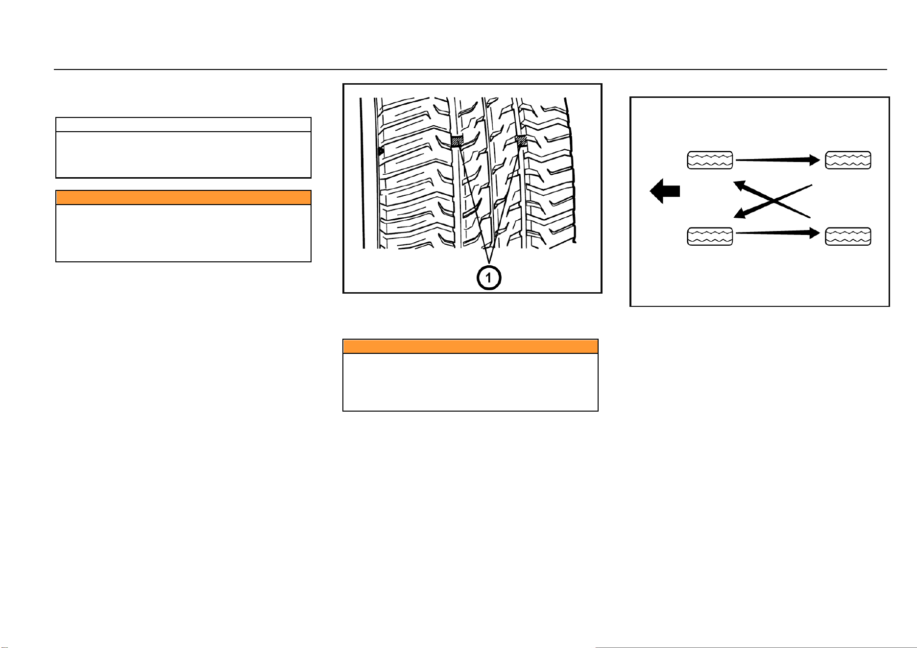
148 Vehicle Service & Maintenance
The vehicle is equipped with radial tires. SGMW suggests
replacing with radial tires of the same size, pattern, tread
wear, temperature and rated speed.
Note
The use of tires with different size than the original
tires may cause the tire and the vehicle component to
interfere with each other, thus causing damage to the
tire and vehicle.
Caution
If the vehicle is equipped with tire pressure monitoring
system, the tire repairing liquid for tire repair may
result in the failure of the tire pressure monitoring
system sensor. It is suggested to go the Aftersales
Service Center for inquiries and repair.
Internal Tread Wear Indicator
Check the tire tread depth as per the tread wear indicator
regularly. The mark on the tire wall indicates the position of
the tread wear indicator.
The tire must be replaced when the tread wear indicator
appears. When the tread depth is equal to or less than 1.6
mm due to wear, the tread wear indicator will appear
between the tread grooves.
Caution
Do not drive the vehicle in case of tire wear or damage.
The worn or damaged tires may lead to the vehicle out
of control and cause collision accidents, resulting in
personal injury and damage of vehicle or other
properties.
Tire Rotation
The front tires and the rear tires have different functions and
therefore have different levels of wear. The front tires wear
faster than the rear tires. In order to prolong the tire life and
avoid uneven tread wear:
1. Conduct tire rotation as per maintenance regulations
in the Manual.
2. Keep a proper tire pressure.
3. Check nuts/bolts for tightening.
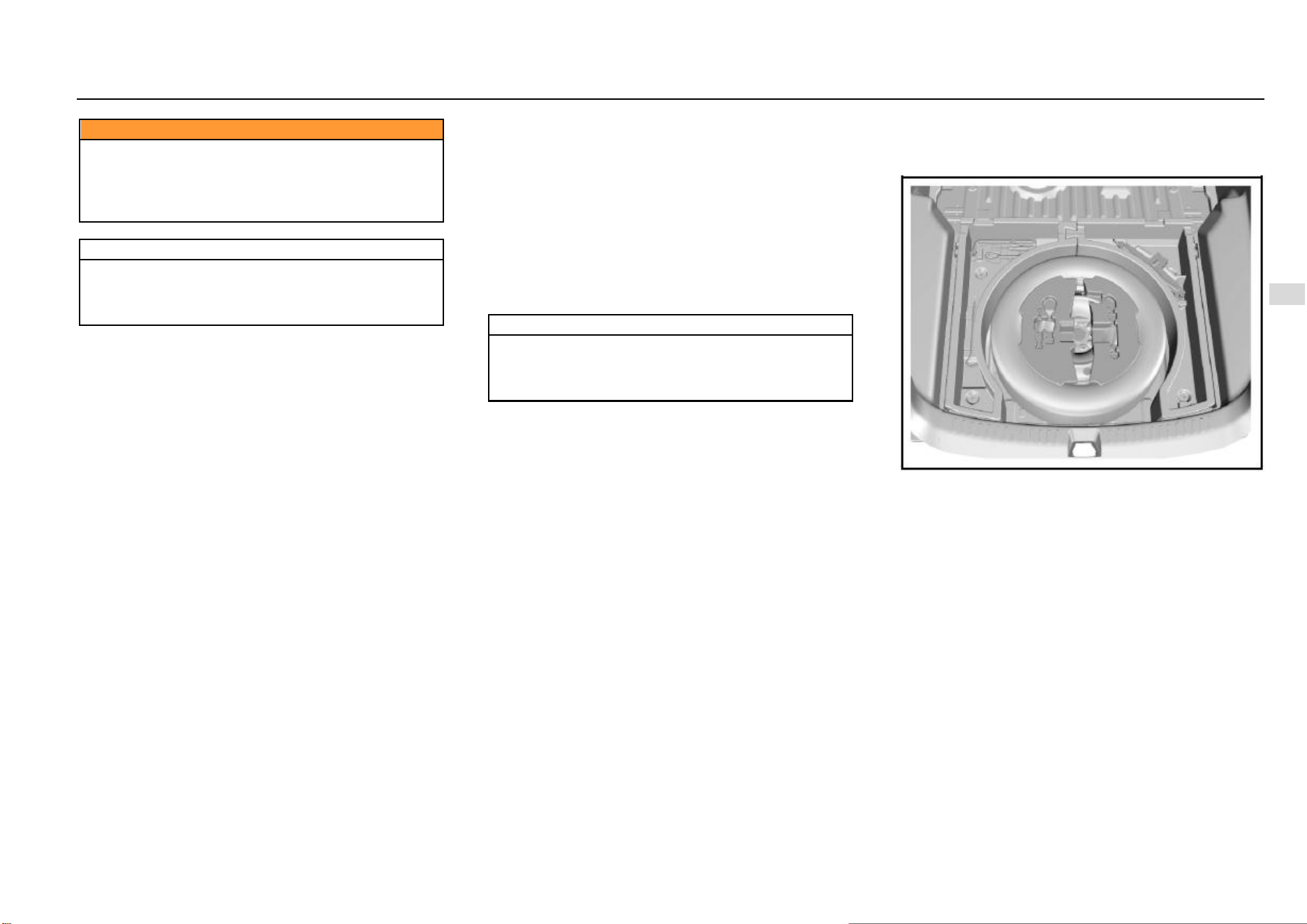
Driving and Controls 149
8
Driving and Controls
Caution
Please use the recommended wheels and wheel
nuts/bolts.
Otherwise, it may lead to the vehicle out of control and
cause collision accidents, resulting in personal injury
and damage of vehicle or other properties.
Note
If the vehicle is equipped with tire pressure monitoring
system, after tire rotation or tire replacement, please
go to the Aftersales Service Center to relearn the tire
pressure.
Winter Tire
The use of winter tires while driving on icy and snowy roads
can improve driving safety. It is suggested to replace with
winter tires when the temperature is below 7 °C. Please
select winter tires with radial tire structure and use such
winter tires on all four wheels. Please use the specified tire
pressure. Do not drive the vehicle at a speed exceeding the
maximum speed specified by the tire manufacturer. All-
weather tires can be used except winter tires.
Tire Chain
Tire chains are only used for emergencies or in areas clearly
defined by law and should be installed on the drive wheels.
Be especially careful when driving the vehicle equipped with
tire chains. Compared with tires without tire chains, when
tires are installed with tire chains, the maneuverability of the
vehicle is poor, and the tire chain may damage the vehicle
tire, suspension or vehicle body. Therefore, use cable tire
chains as far as possible to ensure enough space between
the tire and other parts in the wheel casing. When using tire
chains, carefully read the installation and other related
instructions of the tire chain manufacturer.
Note
After installation of tire chains, it is suggested to drive
the vehicle at the speed of below 30 km/h or the limited
speed recommended by the tire chain manufacturer
(whichever is smaller).
Spare Tire, Jack and Tools
Tool Kit
5-seat Model
The spare tire, jack and tools are under the luggage
compartment and can be seen after raising the luggage
compartment floor. In-vehicle tools include the jack rocker,
socket wrenches, traction hooks and screwdrivers.
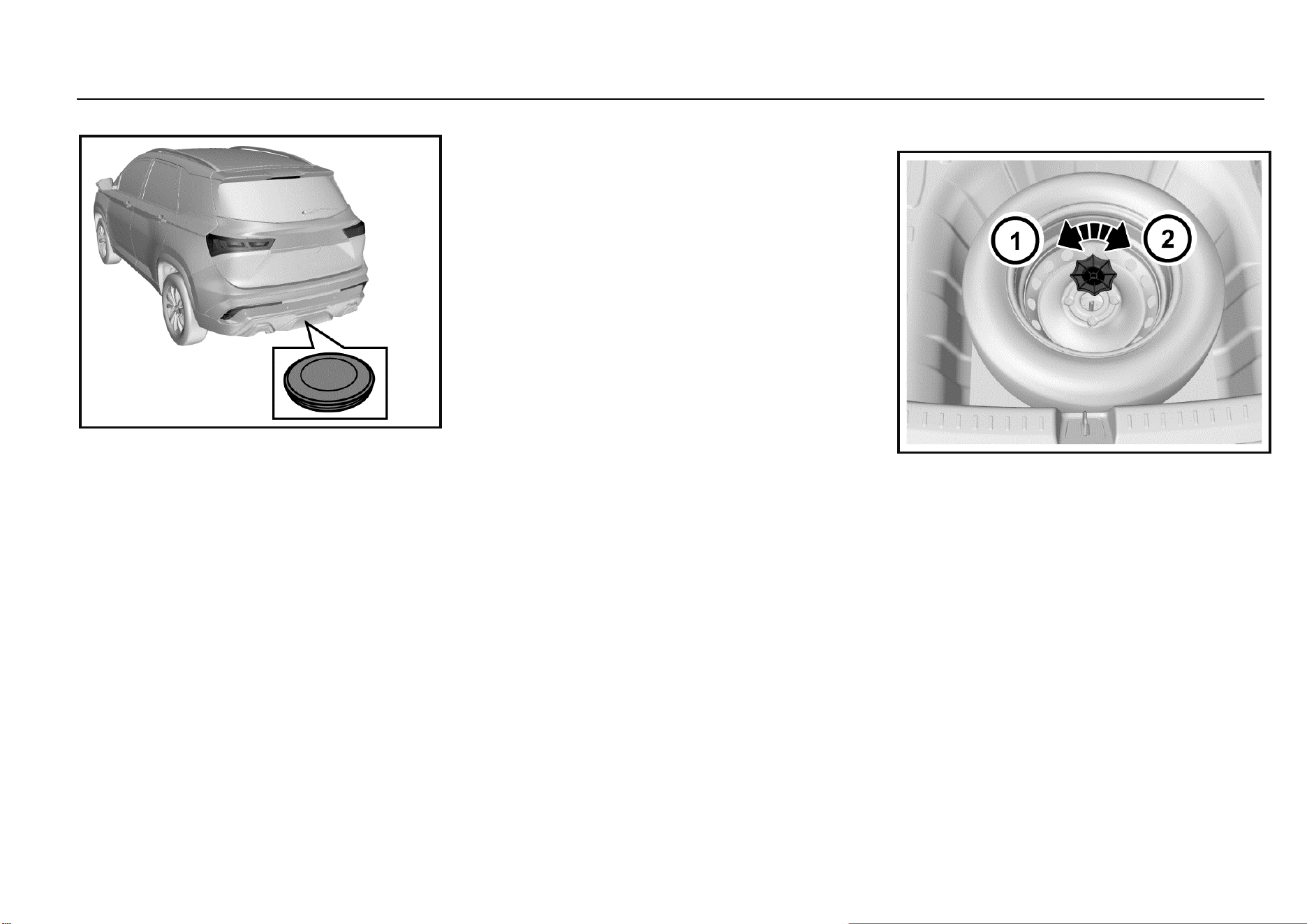
150 Vehicle Service & Maintenance
7-seat Model
The spare tire of 7-seat model is at the bottom of the vehicle
rear floor. The jack and tools are in the luggage
compartment.
Spare Tire
Although the spare tire has been inflated, it will leak after a
period of time. It shall check the inflation pressure regularly.
Refer to the tire load information label for the correct
inflation pressure.
Do not use the spare tire for other vehicles. Do not mix spare
tires or wheels with wheels or tires of other vehicles since
they are not matched. The spare tire should be put together
with its wheel.
Safety Precaution of Tire Replacement:
1. Turn on hazard warning lamp.
2. Drive off the highway to a safe place without traffic.
3. Park the vehicle on a flat and hard surface where the
vehicle will not slip. Take out the warning triangle and
place it at a proper position behind the vehicle (please
comply with traffic rules).
4. Turn off the engine and remove the key.
5. Place the gearshift lever at Gear 1 or reverse gear.
Pull up the parking brake.
6. Have all passengers leave the vehicle and stand in a
safe place.
7. Secure the tire that is diagonal to the tire that need to
be replaced with wedges, blocks or stones.
Failure to comply with these safety precautions may cause
your vehicle to slip off the jack, thus causing serious injury.
Take out the Spare Tires
5-seat Model
1. Open the liftgate and raise the luggage compartment
floor.
2. Take out the tool bracket on the spare tire. If the audio
is equipped, disconnect its cable.
3. Rotate the butterfly nut in the center of the spare tire
counterclockwise to remove it, and then place it
properly.
4. Take out the spare tire.
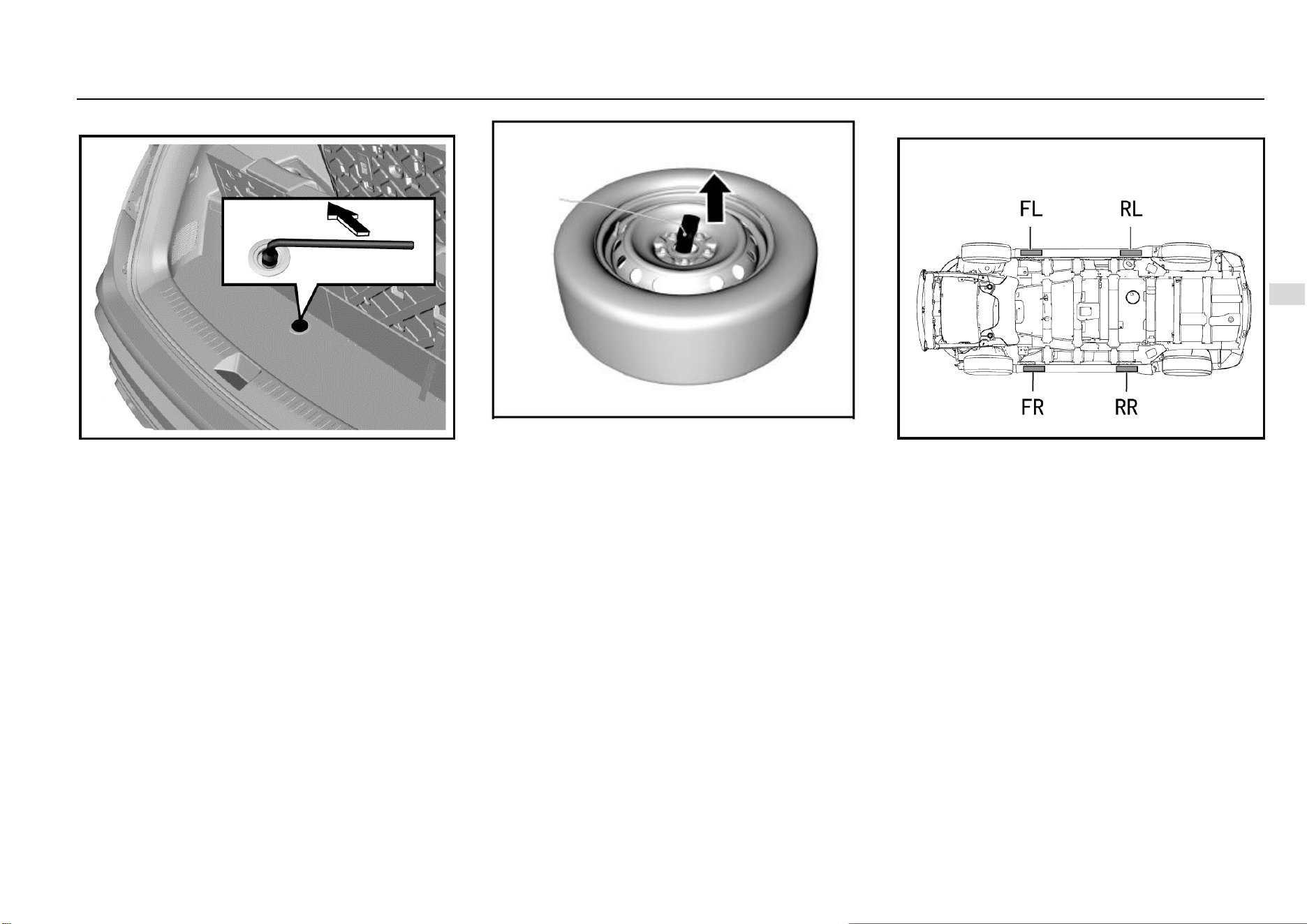
Driving and Controls 151
8
Driving and Controls
7-seat Model
1. Open the liftgate and remove luggage compartment
floor mat. As shown in the figure, there is one bolt on
the storage box bottom board that serves as the shaft
of spare tire lifter.
2. Use a wheel nut wrench to rotate the shaft
counterclockwise until the spare wheel lowers to the
ground.
3. Tilt the holding plate at the end of wire rope and pull it
out of the center hole of the wheel.
Spare tire reassembling procedures:
1. Have the spare tire valve to face upwards and then tilt
the holding plate at the end of wire rope to make it
pass the center hole of the wheel.
2. Use a wheel nut wrench to rotate the shaft clockwise
until the spare tire is lifted off the ground.
3. Check whether the holding plate holds the spare tire
securely.
4. Continue to raise the spare tire until it is tight against
the lower part of the vehicle. The wire rope is
tensioned moderately but not too tightly to guarantee
that it can hold the spare tire firmly.
5. Try to turn the spare tire to check that it is secured. If
the tire is movable, it is necessary to further tighten
the lifter shaft.
6. Put tools and the jack back into the tool kit.
Jack Lifting Point
As shown in the figure above, the jack lifting points are
around the side wall skirt, and there are triangle marks in
corresponding parts for the convenience of searching.
These lifting points are also lifting points of the lifter, and the
lifter tray should be aligned with the triangle mark. The lifting
points have been specifically strengthened. Please be sure
to align them.
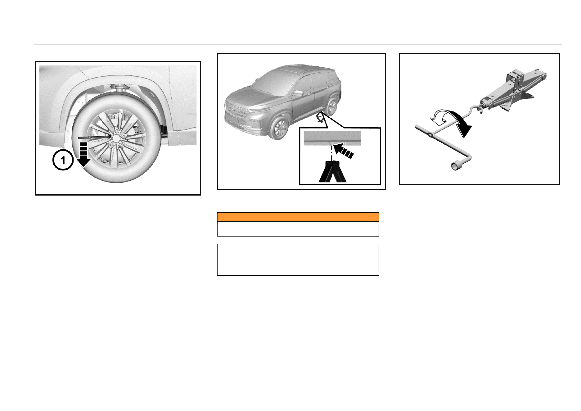
152 Vehicle Service & Maintenance
Tire Replacement
1. Take out tools, the jack and spare tire. Check and
confirm that the tire on the diagonal is secured with
blocks or stones.
2. Use a socket spanner to unscrew the wheel nut by
one turn.
3. Place the jack just below the lifting point closest to the
tire that needs to be replaced. Align the slot on the
jack head with the edgefold.
Caution
Do not remove any nut before wheels are lifted off the
ground.
Warning
Do not attempt to lift the vehicle before the jack is put
into a proper position. The jack should be firmly
secured between the vehicle and the ground.
4. As shown in the figure above, connect the jack rocker
to the jack.
5. Rotate the rocker clockwise to allow the jack to rise
slowly and ensure that the jack head is firmly pushed
into the lifting position.
6. After ensuring that the jack is in the correct position,
continue turning the rocker until the tire is about 3 cm
off the ground.
7. Place the spare tire at the vehicle bottom near the
wheel to be replaced so as to prevent the vehicle from
suddenly slipping.
8. Remove wheel nuts completely.
9. Remove the wheel to be replaced.
10. Install the spare tire on wheel hub.
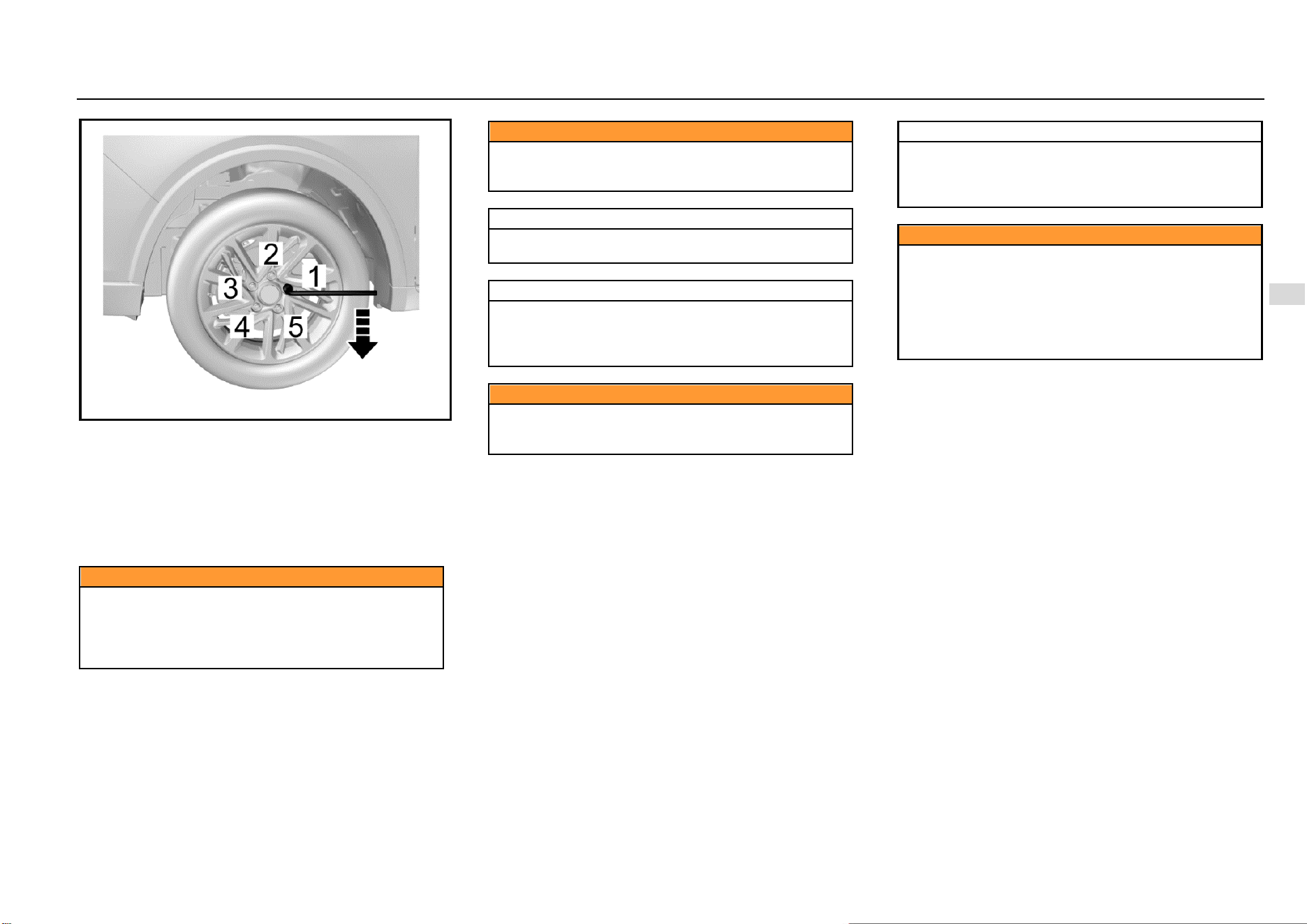
Driving and Controls 153
8
Driving and Controls
11. Install all wheel nuts and tighten them preliminarily.
12. Rotate the jack rocker counterclockwise to lower the
vehicle to the ground stably.
13. Tighten the wheel nuts in the order 1-4-2-5-3 as
shown in the figure above with the torque of 100~130
N·m.
14. Put the leaky tire in the spare tire storage location and
secure it properly. Put tools back to the tool kit and
secure them.
Caution
Make sure to use appropriate nuts and bolts, and
tighten to the proper torque.
The use of incorrect parts or improper tightening of
vehicle nuts may cause damage to the vehicle or
wheel falling off.
Caution
During the entire process the vehicle being lifted by
the jack, ensure that the jack is placed vertically and
no slipping occurs.
Note
Do not lift the vehicle to a height that exceeds the
necessary height for wheel replacement.
Note
Please replace the leaky tire as far as possible for
further use. It shall check the spare tires regularly to
ensure that they can be used safely in case of
emergency.
Caution
Do not work under the vehicle or start the engine when
the vehicle is supported by a jack. The vehicle may slip
off the jack, resulting in serious injury or death.
Note
When the vehicle jacking condition is unsatisfactory
or if you do not have the confidence to safely complete
this work, please contact the Aftersales Service Center
for help.
Caution
Do not apply oil or grease on the wheel nuts or bolts.
Please use correct wheel nuts or bolts.
Use a socket wrench to tighten nuts or bolts firmly.
Please go to the Aftersales Service Center as soon as
possible and tighten wheel nuts or bolts according to
specification. In case of improper tightening, nuts or
bolts may be loose, resulting in accidents.
154 Vehicle Service & Maintenance
Caution
When using the jack, the vehicle may become unstable
and move, causing damage and personal injury.
Please use the correct jack in normal state.
Before lifting, have all passengers leave the vehicle
and stay away from traffic.
The jack is used for wheel replacement only.
Do not jack up the vehicle on a sloped or sliding
ground.
Use the jack at the jack lifting point closest to the
wheel that needs to be replaced.
Stop the wheel on the diagonal with wedges, blocks or
stones so as to avoid vehicle moving.
Caution
Before using the jack, make sure that the parking
brake is pulled up, the transmission is at Gear 1 or
reverse gear.
Avoid replacing wheels at traffic-intensive locations.
Jump Start (Dead Battery)
The vehicle with a low battery can be started by using the
battery of other vehicles by the means of jump start.
If the battery is dead, please contact the Aftersales Service
Center for handling unless you confirm that you have
enough electrical knowledge and you can safely complete
this work.
Caution
Do not start the vehicle by the means of pushing or
dragging. Otherwise, it may damage the catalytic
converter and the transmission and even personal
injury.
Preparation before Jump Start
1. Pull up the parking brake.
2. Ensure that the gearshift lever is at the neutral.
3. Turn off all electrical accessories.
Note
Turn off the audio system before jump start of the
vehicle. Otherwise, the audio system will be damaged.
Please turn off unnecessary electrical devices when
the vehicle is running at low speed for long time (in
case of traffic jam).
Jumper Cable Connection
In case of jump start of the vehicle, connect the jumper cable
in the following order:
1. Clip one end of the first jumper cable to the positive
terminal of the powered battery. (There is a “+” mark
on the battery housing or the terminal)
2. Clip the other end of the jumper cable to the positive
terminal of the dead battery. (There is a “+” mark on
the terminal)
3. Clip one end of the second jumper cable to the
negative terminal of the powered battery. (There is a
“-” mark on the battery housing or the terminal)
4. Connect the other end of the cable to the body ground
of the vehicle that has no electricity.
5. While jump start, it is allowed to start the engine of the
vehicle providing jump start power supply. Try to start
the engine of the vehicle that has no electricity within
one minute, and do not turn the ignition key more than
5s each time. After start, keep the rotation speed at
2000 (r/min) for several minutes.
6. To remove the jumper cable carefully in reverse order,
remove the negative cable first and then the positive
cable.
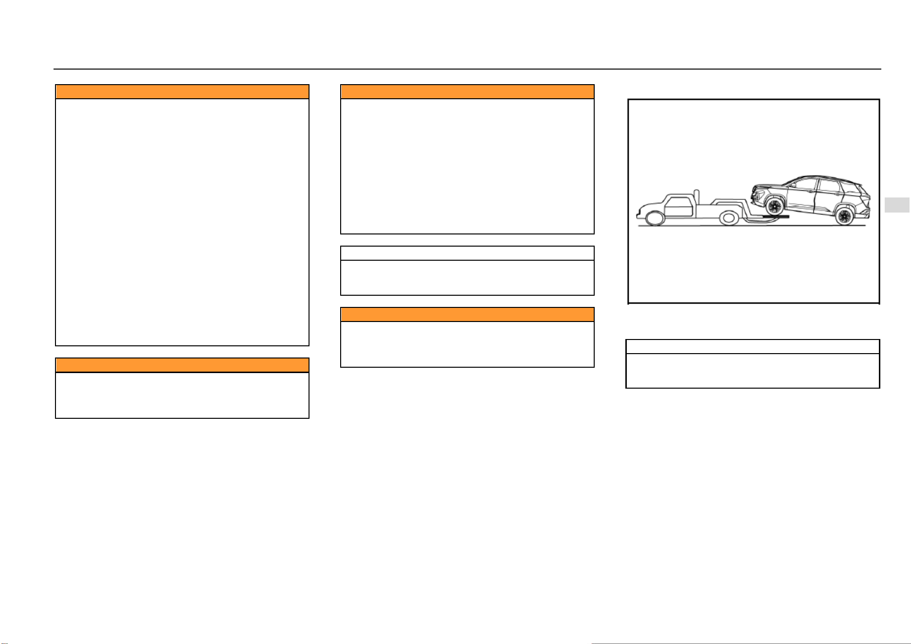
Driving and Controls 155
8
Driving and Controls
Caution
There is the risk of battery explosion. You may be
burned by the battery acid, and an electrical short
circuit can also cause personal injury or damage to the
vehicle.
Do not place the battery near an open flame or
sparks. Do not tilt the vehicle body over the battery in
case of jump start.
Do not allow cable terminals to contact with each
other.
Wear safety goggles when working nearby the
battery.
Do not allow battery acid to come into contact with
eyes, skin, fabric or painted surfaces.
Ensure that the battery used for jump start has the
same voltage as the voltage of original vehicle battery.
Do not disconnect a dead battery from the vehicle.
When starting the engine with jumper cables, violation
of the above precautions or the following instructions
can cause the battery to explode, resulting in people
being burned by battery acid or causing a short circuit.
This may damage the electrical system of both
vehicles and cause serious personal injury.
Caution
Position the jumper cable properly and do not wrap it
around rotating parts of the engine compartment.
Otherwise, it may damage the vehicle and cause
personal injury.
Caution
It shall not be connected to the negative (-) terminal of
the battery when it is finally connected to the vehicle
that needs to be charged.
Connect the last connected clip to the bolt on the
engine cylinder block steel bracket. The last
connection point should be away from the battery as
far as possible.
If the jumper cable is connected to the negative
terminal of an uncharged battery, it may produce
electric arc and cause the battery to explode.
It will cause serious personal injury or damage the
vehicle.
Note
It shall start the engine of the vehicle with a
discharged battery at an interval of about 1 minute,
and the time for each start cannot exceed 15s.
Caution
Do not use the battery as a jump source for other
appliances for a long time. Otherwise, it is easy to
make the battery lose electricity and may even cause
safety accidents.
Vehicle Traction
If vehicle traction is necessary, please contact the
Aftersales Service Center or a professional traction service
company.
Note
Do not tow the vehicle with lifting chain type
equipment. It must use plates or wheel lifting
equipment.
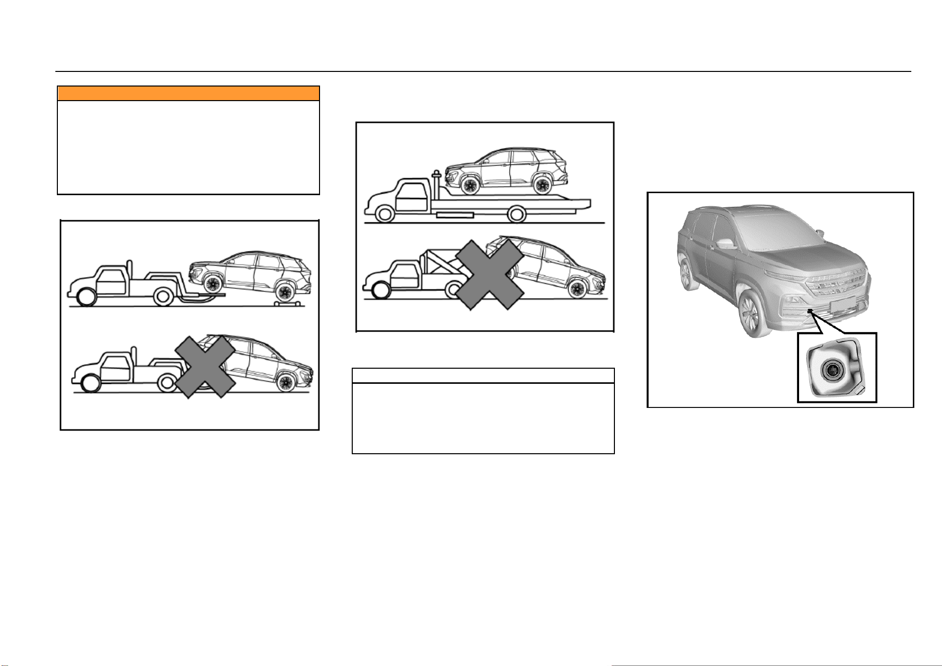
156 Vehicle Service & Maintenance
Caution
● It is prohibited to allow passengers to be seated
in the towed vehicles.
● The towing speed is not allowed to exceed the
safe speed or the indicated road speed limit.
● It is prohibited to use damaged parts that are not
firmly secured onto the vehicle for traction. Failure to
comply with the above precautions may result in
personal injury.
Vehicle Traction with Wheel Lifter
1. Turn on the hazard warning flasher.
2. Turn the ignition switch to ACC position.
3. The transmission must be in neutral gear.
4. Release the parking brake.
5. Front wheels must be off the ground when towing.
Vehicle Traction with Platform Trailer
When towing the vehicle with a platform trailer, turn off the
ignition switch and check that the vehicle is firmly attached
to the trailer.
Note
If the vehicle must be towed from the rear, please use
traction device supporting wheels under the front
wheels. The front wheels should not be on the ground
when the vehicle is towed from the rear. Otherwise, it
may cause serious damage to the vehicle
transmission.
Emergency Trailer
If the tractor is not available in case of an emergency, it can
secure the rope on the front towing hook under the vehicle
for temporary vehicle traction. When the vehicle is towed via
the front towing hook, only traction rope can be used. Do
not use a rigid tow bar.
No matter MT or AT model, engage the neutral (N) gear and
release the hand brake when the vehicle is towed.
Front Towing Hook
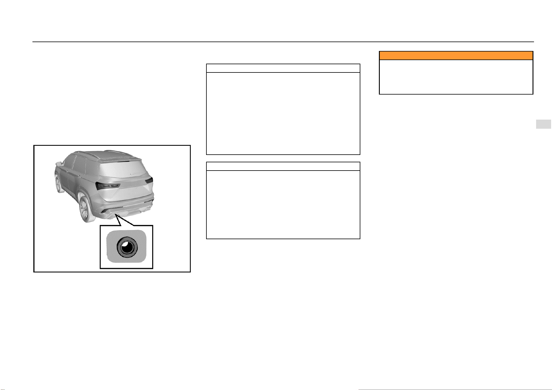
Driving and Controls 157
8
Driving and Controls
There is a hole cover on the right side of the front bumper
of the vehicle. Open it and the fixing hole for hook
installation can be seen.
The towing hook is on the tool bracket under the luggage
compartment floor. Take out the towing hook and install it
into the fixing hole. Rotate the towing hook clockwise to
tighten it completely and insert a socket wrench into the
hook hole to assist tightening. Be sure that the towing hook
is installed firmly before towing the vehicle. When towing the
vehicle, the driver must control steering and braking in the
vehicle. After completion of traction, remove the towing
hook and close the hole cover, and then put the towing hook
back into the tool kit.
Rear Towing Hook
There is a hole cover on the left side of the rear bumper of
the vehicle. Open it and the fixing hole for hook installation
can be seen.
Take out the towing hook and install it into the fixing hole.
Rotate the towing hook clockwise to tighten it completely
and insert a socket wrench into the hook hole to assist
tightening. Be sure that the towing hook is installed firmly
before towing the vehicle.
Do not tow vehicles that are heavier than this vehicle;
otherwise, it may damage the vehicle or cause accidents.
Note
The vehicle may be damaged when it is towed by
ropes. To reduce damage:
The towing hook must be used when other traction
devices are not available.
The vehicle shall be towed from the front only.
Keep the traction rope out of contact with the
bumper.
Make sure that both ends of the traction rope are
firmly secured on the towing hook. Pull the traction
rope for inspection.
Drive the vehicle at a low speed and avoid sharp
turning.
Note
The vehicle may be out of control when it is towed by
ropes.
To reduce damage:
The towing distance shall not be too long, and the
vehicle should be towed at a low speed.
Do not tow the vehicle if the wheel, transmission,
axle, steering or brake damage is damaged.
Do not remove the key from the ignition switch;
otherwise, the steering will be locked so that the
vehicle cannot turn.
Caution
The towing speed shall not exceed 30 Km/h, and the
towing distance shall not exceed 40 Km. When long-
distance towing is required, it is suggested to contact
the Aftersales Service Center or a professional towing
service company for help.

158 Vehicle Service & Maintenance
Getting Vehicle out of Trap
When the vehicle is caught in snow, puddle or other
unstable ground, please follow the procedures below to get
the vehicle out of trap.
1. Turn the steering wheel to the ultimate left and then
turn it to the ultimate right. This will create a vacant
area around the front wheels.
2. Engage the reverse gear and drive gear back and
forth.
3. Reduce wheel idling as far as possible.
4. Release the accelerator pedal when shifting gear.
5. After engaging the gear, depress the accelerator
pedal gently.
If it fails to get the vehicle out of trap, it is necessary to tow
the vehicle.
Caution
When the vehicle is caught in snow, puddle or sandy
soil, you need to get the vehicle out of the trap as soon
as possible.
First, check whether there are obstructions or people
around the vehicle.
During operation, the vehicle may suddenly move
forward or backward, hitting the person or object next
to it.
Note
In order to avoid damage to the transmission and
other parts, the following precautions must be
observed when getting the vehicle out of the trap.
Do not depress the accelerator pedal during gear
shifting or when the transmission is not in a proper
gear position.
High engine speed is not allowed, and wheel idling
shall be avoided.
If it fails to get the vehicle out of trap after several
efforts, consider other methods, such as traction.
Vehicle Maintenance
Cleaning Agent
The manufacturer's suggestions must be observed when
using cleaning agent or other chemical products inside or
outside the vehicle.
Do not use dangerous cleaning agent when cleaning the
interior and exterior of the vehicle. For example:
Acetone
Paint diluent
Porcelain glaze reducing agent
Nail polish remover
When cleaning the interior and exterior of the vehicle, the
following cleaning agents are prohibited unless special
instructions for cleaning stains are included in the fabric
cleaning tips:
Laundry soap
Bleaching powder
Reducing agent
Caution
Some cleaning agents are toxic, corrosive or
flammable. Improper use is very dangerous and may
easily cause personal injury or vehicle damage.
Do not use the following materials for cleaning:
Driving and Controls 159
8
Driving and Controls
Carbon tetrachloride
Gasoline
Benzene
Naphtha
When using any cleaning agent or other chemical products
inside the vehicle, please open the doors for proper
ventilation.
To avoid permanent color change of light-colored interior
trims, do not allow the easy-to-discolor fabrics to come into
contact with the seat liner unless both materials are
completely dry. Fabrics with easy-to-discolor materials are:
Casual clothes
Dyed denim
Leather
Kidskin
Newspapers and decorative paper
Caution
Avoid prolonged exposure to cleaning agents and
other chemical vapors. Such chemical vapor is
extremely dangerous and harmful to the health,
especially in limited space without ventilation.
Vehicle Interior Maintenance and Cleaning
Clean the interior and exterior of the vehicle with proper
cleaning methods and materials.
Use a vacuum cleaner or a banister brush to remove dust
and scum that accumulate on the fabric inside the vehicle
frequently.
Wipe the vinyl plastics and leather trims regularly with a
clean wet cloth.
Remove dust, spots or stains on trims with a suitable
cleaning agent.
Note
Clean the interior trims of the vehicle with proper
cleaning methods and materials.
Otherwise, it will produce water spots, watermarks
and permanent spots, especially during the first
washing. These substances will permanently damage
the vehicle.
Seat Belt Maintenance
Keep the seat belts clean and dry. Prevent seat belts from
being contaminated by polishing agents, oils and chemical
products, especially battery fluid, bleaching powder or
dyestuff. These contaminants will reduce the strength of the
seat belt material. Check all seat belt parts regularly.
Replace any damaged seat belt or part immediately.
The seat belt or related parts that are stretched during the
accident must be replaced, even if the damage is not
obvious or is not visible. The seat belt for replacement must
be new.
SGMW suggests replacing the whole seat belt assembly
after collision. It is not necessary to replace the seat belt
after it is checked to be undamaged and normal by the
Aftersales Service Center for solution.
Note
The seat belt must be kept in good working condition
to maintain its normal function.
Glass Surface
Make sure that the window glass is clean, which helps
reduce glare and improve vision.
Front Windshield Outside Cleaning
Waxes or other materials on the front windshield and blade
may cause the blade to shake when working. Moreover,
such foreign matters are not conducive to keeping the front
windshield clean. Clean the outside of the front windshield
regularly with a non-abrasive cleaning agent.
Water does not form water droplets on the clean front
windshield.
Note
The non-abrasive cleaning agent will scratch the glass
and damage the rear windshield defroster grid lines.
Do not use abrasive cleaning agent on vehicle glass.
Otherwise, it will affect the driver's vision.

160 Vehicle Service & Maintenance
Note
Decals will affect the rear windshield defroster.
Do not paste decals on the inner side of the rear
windshield. Otherwise, it will affect the driver's vision.
Vehicle Exterior Maintenance and Cleaning
Vehicle Washing
The best way to maintain the finish paint of vehicles is to
wash it regularly and keep it clean.
Park the vehicle in the place where is not directly
exposed to sunlight.
Wash the vehicle with the specified neutral soap liquid
and cold or warm water.
Be sure to remove the soap liquid and cleaning agent
from the surface by the means of flushing.
SGMW vehicles are designed to operate under normal
environmental conditions and natural factors.
Note
Do not use household dishwashing detergent to wash
the vehicle. The dishwashing detergent can wash off
paint and wax.
Avoid excessive vehicle washing pressure. Water may
enter the vehicle and damage the interior.
Polishing and Waxing
Regular polishing can remove residues from the surface of
the vehicle. After polishing, use high-quality car wax for
protection.
Note
It is forbidden to clean or polish aluminum trims with
automotive or chrome polishing agent, steam or
alkaline soap liquids. These substances are abrasive
and may damage trims and wheels.
Exterior Bright Metal Parts Protection
Clean the bright metal trims regularly. They are usually
washed with water. When waxing the vehicle, please also
wax these bright metal parts.
Aluminum Wheels and Wheel Trim Cover Cleaning
To maintain the original appearance of the wheel and wheel
trim cover (if any), do not allow them to collect dust or brake
dust.
Clean the wheel/wheel trim cover regularly. Do not use
abrasive cleaning agent or brush that may damage the
finish paint.
Note
Do not use abrasive cleaning agent or brush to clean
aluminum wheels or wheel trim covers.
Corrosion Prevention
SGMW vehicles are designed to have anti-corrosion
capabilities. The use of special materials and protective
paint on most vehicle parts helps maintain satisfactory
appearance, strength and reliability.
Although the surfaces of certain parts inside the engine
compartment or of the underbody may rust, the reliability or
performance of these parts will not be affected.
Metal Plate Damage
If the body needs to be repaired or replaced, ensure that the
repair shop uses proper anti-corrosion materials to restore
the anti-corrosion protection performance.
Foreign Matter Deposition
The following substances may damage the paint surface:
Calcium chloride and other salts
Ice melting agent
Road surface oil and asphalt
Sap
Bird droppings
Industrial dust
Remove harmful substances on the vehicle in time. If
residues cannot be removed with soap liquid, a special
cleaning agent can be used.

Driving and Controls 161
8
Driving and Controls
Finish Paint Damage
Repair the gravel scratches, cracks or deep scratches on
the finish paint as soon as possible. Exposed metal is prone
to corrosion. Quick-drying products can be used to repair
tiny cracks and scratches. Body and paint repair shops can
complete large-scale repairs.
Note
Only safe cleaning agents that are harmless to the
paint surface can be used.
Other cleaning agents may permanently damage the
paint.
Underbody Maintenance
Corrosive substances used for ice and snow melting and
dust prevention may accumulate at the underbody. Failure
to remove these substances will accelerate corrosion and
rusting.
Flush the underbody with clean water regularly. Clean the
part where the mud is prone to accumulate carefully.
Loosen the accumulated dirt in the enclosed area before
flushing with water.
When necessary, please contact the Aftersales Service
Center for service.

162 Vehicle Service & Maintenance
Technical Data
Vehicle Identification...................................................... 163
Vehicle Identification Number (VIN) ..................... 163
VIN on Instrument Panel ...................................... 163
VIN Rubbing Seal under Engine Hood ................. 163
Vehicle Identification Plate ................................... 163
VIN Label under Liftgate ...................................... 163
Seal Engine Number ............................................ 164
Method for Reading Vehicle Identification Number
Information from ECU .......................................... 164
Vehicle Data .................................................................. 165
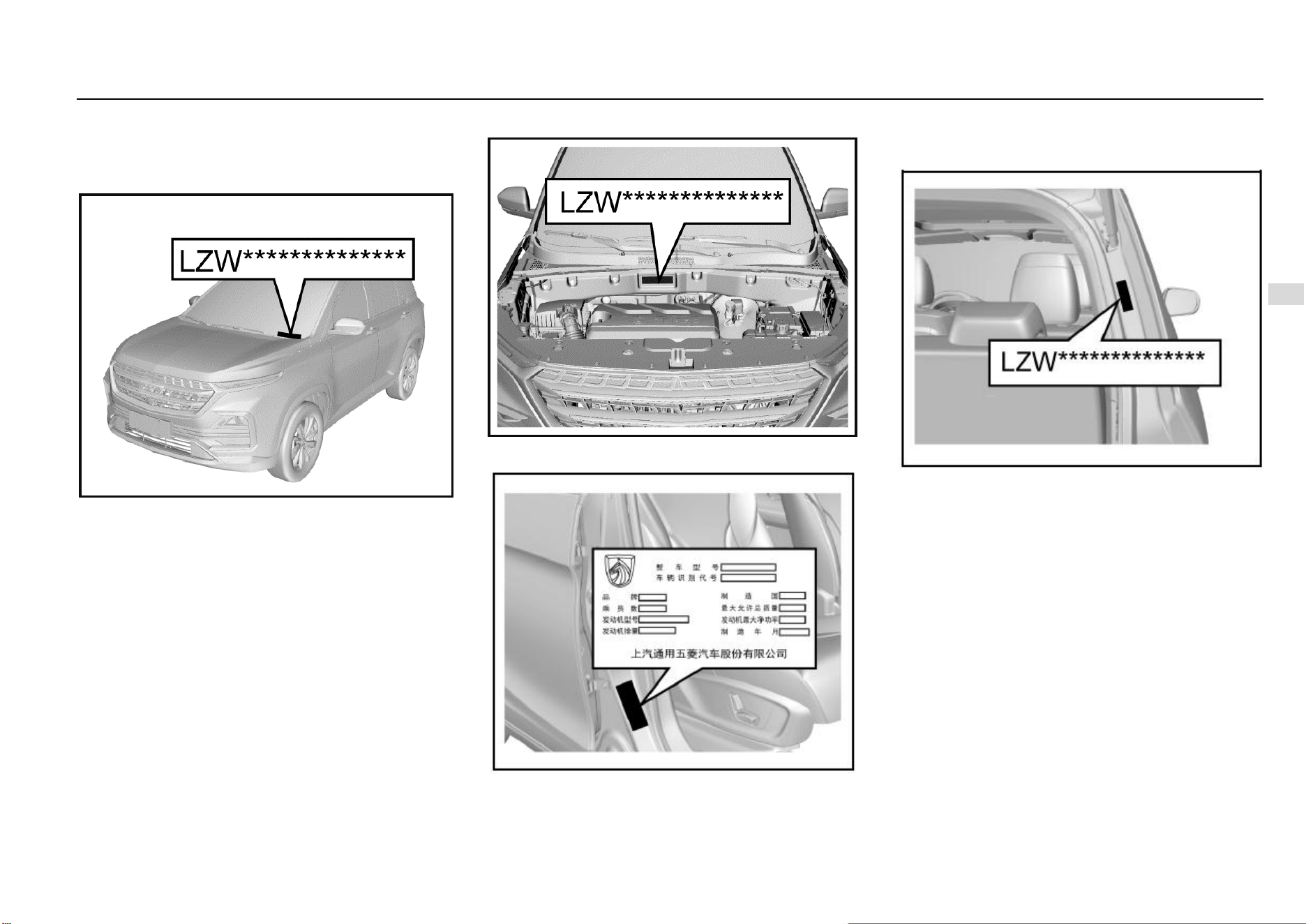
Driving and Controls 163
8
Driving and Controls
Vehicle Identification
Vehicle Identification Number (VIN)
There are 4 commonly used VIN marks on the vehicle.
VIN on Instrument Panel
It is the legal identification mark of the vehicle. The VIN is at
the front corner of instrument panel at the driver’s side. It
can be seen from the outside via the front windshield.
VIN Rubbing Seal under Engine Hood
It is located under the engine hood below the wiper.
Vehicle Identification Plate
This plate is a paper plate and is located on the door frame
at the front passenger side.
VIN Label under Liftgate
Open the liftgate, and it can be seen that the label is below
the liftgate strut support on the right side.
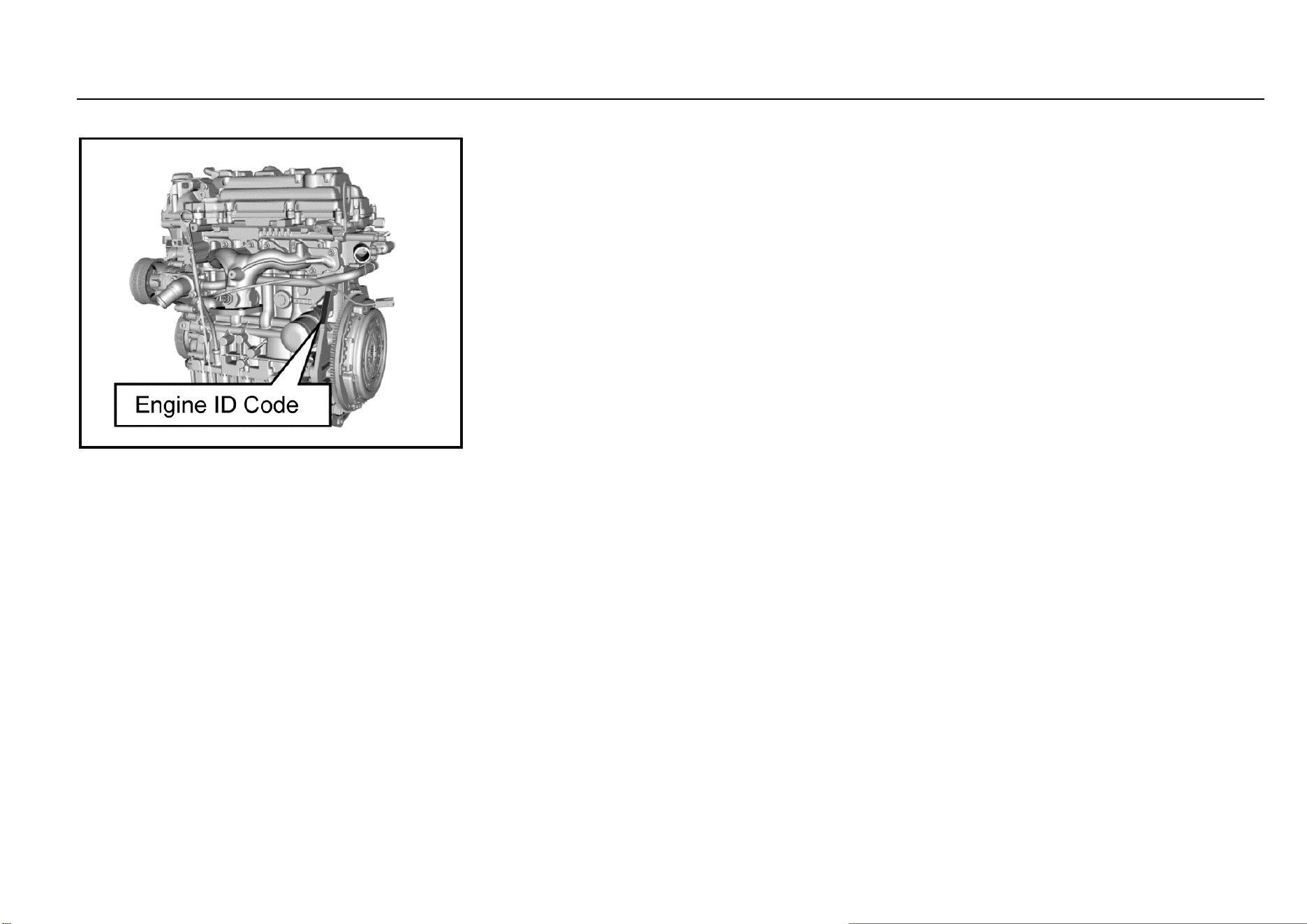
164 Vehicle Service & Maintenance
Seal Engine Number
It is on the engine cylinder block near the flywheel.
Method for Reading Vehicle Identification
Number Information from ECU
Method I: Use X431 Diagnostic Scanner
1. Connect the X431 diagnostic scanner with CAN BUS
II interface to the on-board OBD interface that is
generally located below the instrument panel at the
driver’s side.
2. Turn the vehicle power supply to ON position and turn
on the power of the diagnostic scanner.
3. Click the “Start” button of X431 diagnostic scanner to
enter “Diagnostic Program” and select “Vehicle
Decoding Program” and “Start”, and then, select the
corresponding series. Select the latest diagnostic
software version, click “OK” and wait for the device to
reset and click “OK” again. Select the corresponding
model, “Engine Control System” and the
corresponding electronic control system and then
click “OK”. Select “Version Information” to display the
VIN.
Method II: Use WDS Diagnostic System
1. Connect the data cable of diagnostic system to the
on-board OBD interface that is generally located
below the instrument panel at the driver’s side.
2. Turn the vehicle power supply to ON position and turn
on the diagnostic system.
3. Select “Fault Diagnosis” to select the corresponding
model. Click to enter “ECM”, click “Module
Identification Information” and select “VIN” to display
the VIN.
Note: The methods for reading VIN with diagnostic
equipment of different brand or model may be different.
Please consult the equipment supplier.

Driving and Controls 165
8
Driving and Controls
Vehicle Data
Main Engine Performance Parameters
Item
Unit
Parameter
Engine model: LL5
Transmission model: F625A1, F625A, SH20M6B1, SH20M6B2
Engine type
——
c) Four-stroke, water-cooled, in-line, 16-valve, dual overhead camshaft, DVCP
(dual variable CAM phase), timing chain drive, turbocharging, electronically
controlled gasoline injection, electronically controlled ignition.
Cylinder diameter × travel
mm×mm
73.8×84.7
Displacement
L
1.451
Compression ratio
——
9.5:1
Rated power/speed
kW/(r/min)
110/5500

166 Vehicle Service & Maintenance
Main Engine Performance Parameters (Continued)
Maximum net power/speed
kW/(r/min)
102/5500
Maximum torque/speed
Nm/(r/min)
230/(2000~3800)
Complete vehicle quality
kg
118±2
Idle speed
r/min
750±50
Driving type
——
Front-engine front-drive
Fuel type and grade
——
92# and above motor gasoline
Complete vehicle emission standard
——
1. The measuring method for vehicle loaded mode emission should comply
with provisions of GB 18352.5 and DB 11/946.
2. The vehicle model is shown on the vehicle identification plate. The
penultimate letter represents the emission level; the letter “Y” represents the
National V II Phase standard, and the number “6” represents the National VI
standard. Example: For the vehicle model “LZW6477BMYZ”, the penultimate
letter “Y” refers to the National V II Phase standard.

Driving and Controls 167
8
Driving and Controls
Main Quality Parameters of Complete Vehicle
Item
Unit
Parameter
LZ-W6477-BMYZ
LZ-W6477-BMVYZ
Seats
Person
7
5
Curb weight
kg
1541
1435,14-90
Front axle load of
curb weight
kg
870
840,870
Rear axle load of
curb weight
kg
671
595,620
Total mass
kg
2000
1850
Front axle load
kg
1000
930
Rear axle load
kg
1000
920

168 Vehicle Service & Maintenance
Power Performance Parameters
Item
Unit
Parameter
Testing method
LZW6477BMYZ/ LZW6477BMVYZ
Maximum vehicle speed
Km/h
≥170
GB/T 12544—2012
Maximum climbing gradient
%
≥30
GB/T 12539—1990

Driving and Controls 169
8
Driving and Controls
Main Liquid Parameters
Name
Trade mark
Capacity, unit unmarked: L
LZW6477BMV- YZ/
LZW6477BMYZ
Motor gasoline
92# and above motor gasoline
52
Engine lubricating oil
SM/GF-4 5W-30
4.0
Transmission fluid
SAE 75W/90
2.0±0.15
Coolant
Ethylene glycol antifreezing
fluid
7.1~7.6
Brake fluid (including hydraulic
clutch fluid)
DOT4
0.45±0.05
A/C refrigerant
HFC-134a
570±20g

170 Vehicle Service & Maintenance
Main Technical Parameters of Complete Vehicle
Item
Unit
Parameter
LZW6477BMVYZ
LZW6477BMYZ
Total length
mm
4655
Total width
mm
1835
Total height (no load)
mm
1760
Wheel base
mm
2750
Front suspension
mm
950
Rear suspension
mm
955
Front wheel track
mm
1554
Rear wheel track
mm
1549
Approach angle (no load/full load)
.
20/19
Departure angle (no load/full load)
.
23/20
22/18

Driving and Controls 171
8
Driving and Controls
Main Technical Parameters of Complete Vehicle (Continued)
Minimum ground clearance (full load)
mm
185
Minimum turning diameter
m
11.9
Name and Position of Parts not Included in Vehicle Overall Dimensions as Required by GB1589
Name
Position
Wiper and washer
Vehicle rear end
Exterior identifications, including the product trademark, company name identification and other
identifications that reflect vehicle characteristics
Vehicle front end, rear end and vehicle side
Lighting and optical signal device
Vehicle front end, rear end and vehicle side
Rear identification plate (with LOGO)
Vehicle rear end
Detachable vehicle hooking or dragging device
Vehicle front end and rear end
Exhaust tail pipe
Vehicle rear end
Indirect vision device
Vehicle front end, rear end and vehicle side
Anti-collision rubber block and similar devices
Vehicle side
Flexible protrusion of spray-suppression system
Vehicle side
Handle and switch
Vehicle side

172 Vehicle Service & Maintenance
Name and Position of Parts not Included in Vehicle Overall Dimensions as Required by GB1589 (Continued)
Deformed portion of the tire wall right above the tire contact point
Tire side
Soft part of the antenna
Roof
Note: Refer to the national standard GB1589 for details of the unlisted parts.

Driving and Controls 173
8
Driving and Controls
Tire Inflation Pressure (Cold State)
Tire model
Item
Tire inflation pressure (unit: kPa)
No-load
Full-load
215/60R17
Front tires
230±10
230±10
Rear tires
230±10
230±10

174 Vehicle Service & Maintenance
Wheel Alignment Parameters (No Load)
Item
Range (unit: degree)
Vehicle model equipped with twist beam semi-
independent rear suspension
Vehicle model equipped with independent
rear suspension
Front wheel
Camber
-0°26′±45′
Kingpin caster angle
4°17′±45′
3°58′±45′
Toe-in
0°±5′
Kingpin inclination angle
12°29′±1°
Rear wheel
Camber
-1°±45′
-1°10′±45′
Toe-in
11′±20′
10′±15′

Driving and Controls 175
8
Driving and Controls
Fuel Economy Parameters
Item
Unit
Requirement
Requirement
Test methods
LZW6477B- MYZ
LZW6477B- MVYZ
Fuel consumption
under general
operating condition
L/100 km
≤7.0
≤6.9
GB/T 19233—2008

176 Vehicle Service & Maintenance
Other Parameters
Item
Parameter
Requirement for dynamic balance of wheels
Dynamic unbalance value<15 g
Reasonable range of brake pedal free travel
<30 mm
Minimum scrapping thickness of front brake disc
24 mm
Minimum scrapping thickness of front brake lining
2 mm
Minimum scrapping thickness of rear brake disc
8.75 mm
Minimum scrapping thickness of rear brake lining
2mm


178 Accessory List
Accessory List
S/N
Name
Quantity
Remarks
1
Motor Vehicle Factory Certificate
1
2
Vehicle Consistency Certificate
1
3
Owner's Manual of Vehicle Audio System
1
Distribute according to vehicle configuration
4
In-vehicle package (including Service & Maintenance and Owner’s
Manual and Owner’s Operation Manual)
1
5
In-vehicle tools
1
6
Warning triangle
1
7
Mobile ashtray *
1
Distribute according to vehicle configuration
8
Reflective vest
1
Distribute according to regulatory requirements and put it in the glove
box. When you need to get off the vehicle in an emergency, wear a
reflective vest first.
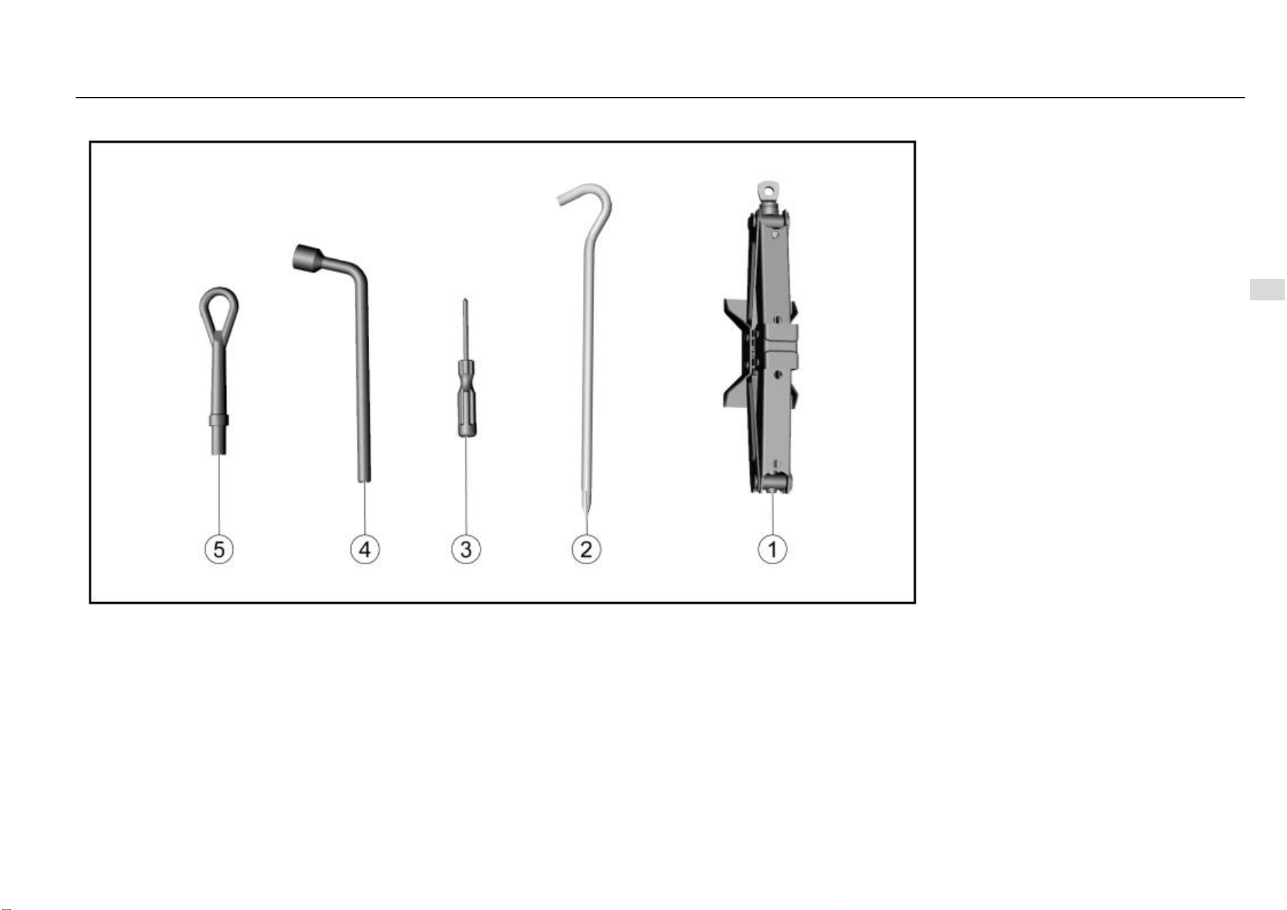
Driving and Controls 179
8
Driving and Controls
In-vehicle tools
1. Jack
2. Jack rocker
3. Screwdriver
4. Wheel nut wrench
5. Towing hook

180 Maintenance Procedures
Maintenance Procedures
Important Information .................................................... 181
Warranty ........................................................................ 182
Quality Assurance Service Regulations ............... 182
Maintenance .................................................................. 186
Maintenance Purpose .......................................... 186
Product Defect Report ................................................... 207
Inquiry Way of Aftersales Service Center Contact 错误!未定
义书签。

Driving and Controls 181
8
Driving and Controls
Important Information
1. We suggest you to go to the Aftersales Service Center
for vehicle maintenance and repair since that only the
center knows your vehicle best. You will be provided
with original accessories and professional technical
services at the center. Quality can only be guaranteed
by the center. Non-household vehicles (such as
vehicles used by units etc.) are provided with services
within the warranty period, and the household
vehicles are provided with services within warranty
period and “three guarantees” period.
2. The Company is not responsible for any problem
caused by the use of non-original parts and
components (including but not limited to the non-
compliance of environmental emissions due to the
use of non-original parts and components or other
violations of laws and regulations).
3. For those who fail to perform regular maintenance at
a service center during the quality assurance period,
the quality assurance service is not provided to the
contents related to maintenance and the fault caused
consequently. A new vehicle can enjoy free
maintenance (including material fees and man-hour
fee) for the first time after it has been driven for 3
months or 5000 km (whichever comes first). This
maintenance must be carried out by a service center
with the owner holding the purchase invoice and this
Manual.
4. The Manual must be shown to the service center
during maintenance or repair. Be sure to keep this
Manual and the maintenance and repair information
recorded in the Manual properly. They are an
important basis for you to enjoy the quality assurance
service and for the service center to analyze the
cause of the failure. The Maintenance Record Form
must be stamped with the seal of the service center.
The service center does not have the right to receive
and keep the Manual. For vehicles that meet the
quality assurance service conditions, the service
center shall not refuse to provide quality assurance
services for any reason.
5. In the case that the user submits a written return or
transfer request, after the final appraisal and
confirmation by SAIC GM Wuling Automobile Co.,
Ltd., the dealer can handle the return or transfer
procedures and charge compensation fee based on
the purchase price (the invoice of the sales unit shall
prevail). And use mileage to collect compensation
fees. Calculation formula: [(vehicle price (RMB) ×
total mileage (km))/1000] × 0.8%.
6. After the driver leaves the vehicle, do not store
valuables in the vehicle. Otherwise, the Company will
not assume responsibility.
7. If you need help, please contact the nearest service
center or call SAIC GM Wuling Automobile Co., Ltd.
Service hotline: 400-86-12345, 400-889-5050; e-mail:
8. The time or mileage in this Manual whichever comes
first shall prevail. It will no longer be explained
particularly if there is no necessary.
9. Any matters not covered in this Manual and those that
are inconsistent with the relevant national laws and
regulations shall be subject to the relevant national
laws and regulations.

182 Maintenance Procedures
Warranty
Quality Assurance Service Regulations
1. After vehicle defects caused by product design,
manufacturing, assembly, raw material defects and
other factors during the quality assurance period
being identified by SAIC GM Wuling Automobile Co.,
Ltd., to protect the environment protection and
sustainable development, it is mainly repair defective
parts for free. In the case that defective parts cannot
be repaired or have no repair value, the repair method
of parts replacement shall be adopted. The parts and
components used for repair or replacement are
provided by the manufacturer or are qualified by
inspection.
2. Within the quality assurance period, if the vehicle
needs to be repaired due to defects in the scope of
the quality assurance service, please allow the
service center to have sufficient time to make
necessary repairs. The service center will return your
vehicle as soon as possible, and the replaced parts
are owned by the Company.
3. Except for mandatory regulations of Chinese laws, the
quality assurance service provided by this Manual is
the sole responsibility of the Company to owners.
4. The transportation time of special parts and
components and the time taken to go out for rescue
are not included in the maintenance time. For the
definition of special parts and components, please
refer to the appendix of the appendix of the Three-
guarantees Certificate.
5. Non-household vehicles (such as vehicles used by
units etc.) are provided with services within the
warranty period, and the household vehicles are
provided with services within warranty period and
“three guarantees” period.
Owner’s Rights and Obligations
For the new vehicle parts and accessories at own expense,
the Owner has the right of being provided with quality
assurance service under the precondition of fulfilling the
basic obligations while complying with other relevant
provisions of this Manual. The following are the basic
obligations that the Owner needs to perform in order to
obtain the right of enjoying quality assurance service:
1. Within the quality assurance period, perform regular
maintenance at the service center as specified and
correctly use and operate according to the regulations
in this Manual.
2. Use original accessories provided by the Company;
carry out maintenance, repair and replacement at the
service center and provide valid certification.
3. To ensure the safety of the Owner and the vehicle, for
the faulty vehicle, the Owner should keep its original
status and contact SAIC GM Wuling Automobile Co.,
Ltd. or a service center as soon as possible. Do not
disassemble or repair the vehicle by yourself without
the permission of SAIC GM Wuling Automobile Co.,
Ltd. or a service center.
Quality Assurance Service Scope
1. Defects within the quality assurance service scope:
refer to vehicle defects caused by product design,
manufacturing, assembly, raw material defects and
other factors during the quality assurance period
being identified by SAIC GM Wuling Automobile Co.,
Ltd.
2 . Within the quality assurance period, material fees and
man-hour fee incurred by vehicle maintenance due to
defects within the scope of the quality assurance
service will not be charged to the Owner.
3. Supplementary material fees (e.g. engine oil,
transmission fluid and brake fluid etc.) that are
incurred due to quality assurance service will not be
charged to the Owner.
Conditions not Included in Quality Assurance Service
Scope
1. Use for rent or operation;
2. Forging or illegal obtaining of relevant vehicle
purchase certificate and in-vehicle manual data etc.;
3. Failure to provide purchase certificate when the
information about vehicle purchase is required;
4. The Manual being shown beyond the quality
assurance period or not shown, or failure to provide
relevant certificate for re-applying this Manual, or
failure to simultaneously show the Manual, purchase
invoice and settlement issued by the service center
for self-paying accessories;
5. Failure to completely fulfill basic obligations of the
Owner;
6. Faults caused by changes to the original vehicle
structure, including assembling, refitting or adding
equipment without permission;
7. Cheating during the quality assurance period,
including but not limited to deliberate changes to the
odometer;
8. Refusing quality assurance services from SAIC GM
Wuling Automobile Co., Ltd. or the service center;

Driving and Controls 183
8
Driving and Controls
9. Secondary failures caused by continuous driving
when the vehicle is faulty, including but not limited to
the damage caused by continuous driving when the
coolant temperature gauge indicates high
temperature;
10. Product failure or missing of parts due to improper
use, storage or maintenance by the Owner, including
but not limited to failure of engine or electrical
equipment and other parts and components due to
vehicle wading, or faults caused by theft, overloading,
abnormal control, racing, exposure to the sun and
long-term parking, etc.;
11. Damages due to traffic accidents, natural disasters or
other force majeure, including but not limited to car
accident, floods, sandstorms, earthquakes, hail,
mudslides and military operations etc.;
12 . Maintenance materials to be replaced regularly for
maintenance except for the first maintenance, e.g. oil
and filter element etc.;
13. Defects caused by human or external factors, e.g.
damage, rusting, fading and scars etc., including but
not limited to foreign body scratches, animal
excrement contamination and environmental pollution
etc.;
14. Symptoms that are no perceived effects on the quality
or function of the vehicle under normal circumstances,
including but not limited to minor noise or vibration;
15. Economic loss or additional expenses caused by
improper use of the vehicle, e.g. loss of time, personal
property and income.

184 Maintenance Procedures
Quality assurance period
The quality assurance period is divided into original vehicle parts quality assurance period and self-paying accessories quality assurance period according to the parts. The former is divided into
the warranty period and “three guarantees” period according to the nature; the latter only consists of the warranty period. The quality assurance period does not change with the ownership of
the vehicle. However, if there is any other agreement between the sales unit and the Owner, the signed agreement shall prevail, and in such case, relevant policies and provisions of this Manual
will not apply, e.g. the second-hand vehicle trading agreement, agreement related to inventory cheapened vehicles and relevant agreements of defective vehicles. The quality assurance period
is specifically defined as follows:
1. Original vehicle parts quality assurance period: It refers to the quality assurance period for the original vehicle parts when purchasing a new vehicle from the date of purchase (based
on the invoice issued by the sales unit) and the mileage at this time. The Three-guarantees Certificate will indicate the date of purchase and be signed by the Owner. The original vehicle
parts quality assurance period is divided into the warranty period and “three guarantees” period according to the time. Refer to the appendix of the Three-guarantees Certificate for details.
The Owner should present this Manual to the service center when requesting the original vehicle parts quality assurance service. If the odometer fails or is damaged and has not been
repaired in time, resulting in failure to confirm the mileage, the accumulated mileage will be calculated as 300 km/day from the date of purchase. If there is a record of quality assurance
service, it will calculate as 300 km/day from the date of repair, and the mileage will be accumulated along with the mileage recorded on the day of repair. If the odometer is replaced, the
mileage should be calculated with the mileage recorded by the previous odometer.
2. Warranty period: It refers to the time and mileage range of free maintenance under the conditions of in conformity with relevant policies and provisions of this Manual and relevant national
laws and regulations.
3. “Three guarantees” period: It refers to the time and mileage range of maintenance, exchange and return under the conditions of in conformity with relevant policies and provisions of this
Manual and relevant national laws and regulations. At present, there is no “three guarantees” period for the self-paying accessories.
4. Self-paying accessories quality assurance period: It is the period from the date of purchase (based on the purchase invoice) of the original parts of the Company by the Owner at the
service center at his/her own expense and the mileage at that time. The date of purchase and the mileage at that time shall be noted by the service center on the purchase invoice, and
the invoice shall be signed by the Owner.
The Owner shall present the Manual, the purchase invoice and settlement issued by the service center when requesting the service center for self-paying accessories quality assurance
service. If the odometer fails or is damaged and has not been repaired in time, resulting in failure to confirm the mileage, the accumulated mileage will be calculated as 300 km/day from
the date of purchase. If the odometer is replaced, the mileage should be calculated with the mileage recorded by the previous odometer. The self-paying accessories quality assurance
period does not consist of the “three guarantees” period. Refer to the table below for details:

Driving and Controls 185
8
Driving and Controls
Self-paying Accessories Quality Assurance Period
S/N
Part
Warranty period
Three-guarantees validity
1
Fuse, relay, wiper blade, glass of whole vehicle, drive belt, oil filter, fuel filter, tire, air/ A/C filter element, brake lining,
brake shoe, clutch friction plate, canister, spark plug, bulbs of whole vehicle, corrugated pipe and rubber parts
None
None
2
Battery, thermostat, exhaust pipe gasket, plastic parts, lamps, sunshade and digital clock
6 months or 10,000 km
None
3
All parts not listed in this table
12 months or 20,000 km
None

186 Maintenance Procedures
Maintenance
Maintenance Purpose
Proper vehicle maintenance will not only keep your vehicle
in good working conditions but also be beneficial to
environmental protection. To protect the environment and
maintain a good condition, please carry out vehicle
maintenance correctly.
Maintenance System
All matters stipulated in this system apply to vehicles in the
quality assurance period and are only for recommendation
or reference for vehicles out of the quality assurance period.
1. The first maintenance of vehicles must be carried out
within 3 months or 5,000 km of mileage (whichever
comes first). You will have the right to be provided
with the first free maintenance service within 3 months
or 5,000 km of mileage (whichever comes first), and
you will lose such right if any of the time and mileage
exceeds the conditions. Free maintenance includes
the man-hour fee and material fees for maintenance
work. The cost of any maintenance other than the free
service (including follow-up regular maintenance)
shall be borne by the Owner.
2. The maintenance service provided to the Owner
should be carried out in the service center. After the
maintenance is completed, the service center shall fill
in the “Maintenance Record Form”, and the Owner
shall sign it after confirmation.
3. The quality problems found during maintenance
should be handled according to the provisions of the
quality assurance service.
4. The Maintenance Specification Table stipulates the
time and mileage for each maintenance. The
maintenance must be maintained at the service
center within the quality assurance period according
to the time limit specified in the Maintenance
Specification Table. After the maximum quality
assurance period, e.g. after 5 years or 100,000 km of
mileage, it is suggested to go to the service center for
appropriate maintenance according to the time and
mileage interval specified in the Maintenance
Specification Schedule (or in advance as
appropriate).

Driving and Controls 187
8
Driving and Controls
After 5 years or 100,000 km of mileage, it is suggested to go to the service center for appropriate maintenance according to the time and mileage interval specified in the Maintenance Specification
Table (or in advance as appropriate).
1. Routine Maintenance Specification Table: When the vehicle is operated in a flat and less dusty environment, maintenance should be performed in accordance with the requirements of
Routine Maintenance Specification Table or carried out in advance as appropriate:
Maintenance time
Maintenance items
(Time or mileage whichever comes shall prevail)
Time (months)
3
6
12
18
24
30
36
42
48
54
60
66
Mileage (×1000 km)
5
10
15
20
25
30
35
40
45
50
55
60
Engine
Engine oil and oil filter ①
R
R
R
R
R
R
R
R
R
R
R
R
Fuel filter
I
R
I
R
I
R
I
R
I
R
I
Air/ A/C filter element
I
I
R
I
R
I
R
I
R
I
R
I
Spark plug
I
R
I
R
I
Engine coolant ①
I
I
I
I
R
I
I
I
R
I
I
I
State of intake and exhaust manifolds
I
I
I
I
I
I
Drive belt and tensioning pulley
I
I
I
I
I
I
I
Cooling system pipeline and joint
I
I
I
I
I
I
I
I
I
I
I
I
Engine suspension fastening bolt and nut
I
I
I
I
I
Engine harness and sensors
I
I
I
I
I

188 Maintenance Procedures
Maintenance time
Maintenance items
(Time or mileage whichever comes shall prevail)
Time (months)
3
6
12
18
24
30
36
42
48
54
60
66
Mileage (×1000 km)
5
10
15
20
25
30
35
40
45
50
55
60
Throttle body cleanliness and positive crankcase ventilation system
condition
I
I
I
I
I
I
I
I
I
I
I
Canister
I
I
I
I
I
I
I
I
I
I
I
Fuel line & joint and fuel tank
I
I
I
I
I
I
I
I
I
I
I
I
Chassis and Body
Check the parking brake function and travel
I
I
I
I
I
I
I
I
I
I
I
I
Brake system line (including vacuum booster)
I
I
I
I
I
I
I
I
I
I
I
I
Brake fluid (including clutch mechanism) ①
I
I
I
I
I
I
R
I
I
I
I
I
Manual transmission fluid ①
R
I
I
I
R
I
I
I
R
I
I
I
Seat belt and buckle state and function
I
I
I
I
I
I
Driving and Controls 189
8
Driving and Controls
Maintenance time
Maintenance items
(Time or mileage whichever comes shall prevail)
Time (months)
3
6
12
18
24
30
36
42
48
54
60
66
Mileage (×1000 km)
5
10
15
20
25
30
35
40
45
50
55
60
Wheel nut
I
I
I
I
I
I
I
I
I
I
I
I
Front/rear brake system related working components
I
I
I
I
I
I
I
I
I
I
I
I
Steering wheel and steering linkage
I
I
I
I
I
I
I
I
I
I
I
Door lock, hinge and stopper; lubricate if necessary
I
I
I
I
I
I
I
I
I
I
I
Clutch and brake pedal free travel check
I
I
I
I
I
I
I
I
I
I
I
I
Chassis and underbody fastening bolt and nut
I
I
I
I
I
I
I
I
I
I
I
I
Tire rotation ②
I
I
R
I
I
I
R
I
I
I
I
Tire condition and tire pressure (including spare tires) ②, ③
I
I
I
I
I
I
I
I
I
I
I
I
Propeller shaft sheath and ball pin sheath
I
I
I
I
I
I
I
I
I
I
I
Front/rear spring and shock absorber
I
I
I
I
I
I
I
I
I
I
I
I
Cable/flexible shaft inspection (gear shift, accelerator pedal, clutch, hand brake etc.)
I
I
I
I
I
I
I
I
I
I
I
I
Air Conditioning and Electronics

190 Maintenance Procedures
Maintenance time
Maintenance items
(Time or mileage whichever comes shall prevail)
Time (months)
3
6
12
18
24
30
36
42
48
54
60
66
Mileage (×1000 km)
5
10
15
20
25
30
35
40
45
50
55
60
Air Conditioning System
I
I
I
I
I
Illumination and signal device
I
I
I
I
I
I
I
I
I
I
I
I
Windshield washing system
I
I
I
I
I
I
I
I
I
I
I
I
Battery connection and state
I
I
I
I
I
I
I
I
I
I
I
I
﹡ Description of symbols in the table
I- Inspect these items and associated parts; correct, tighten, clean, supplement, adjust or replace if necessary.
R- Replace or change.
① Refer to “Main Liquid Parameters” in Chapter “Technical Data” of this Manual.
② If necessary, perform four-wheel alignment or tire dynamic balancing.
③ Inspect the condition of tires before driving and check the tire pressure at least once a month with a tire pressure gauge.
2. Non-routine Maintenance Specification Table: When the vehicle is operated under the following severe conditions, maintenance should be performed in accordance with the requirements
of Non-routine Maintenance Specification Table or carried out in advance as appropriate:
1. Most of the single travel distance is less than 10 km;
2. Always drive the vehicle at the outdoor temperatures of below 0°C or above 35°C;
3. In traffic jams, start and stop the vehicle repeatedly or drive the vehicle at idle or low speed for a long time;
4. Suddenly accelerate, decelerate or drive the vehicle at high speed driving frequently;
5. Frequently drive the vehicle on dusty roads, in hilly or mountainous areas;
6. Vehicles are used as police vehicle, taxis and other special vehicles for leasing or other operations.

Driving and Controls 191
8
Driving and Controls
Non-routine Maintenance Specification Table
Item
Maintenance interval
Engine oil and oil filter
Replace every 3 months or 5,000 km or in advance as appropriate
Transmission fluid
Replace every 18 months or 30,000 km or in advance as appropriate
Engine coolant
Replace every 12 months or 20,000 km or in advance as appropriate
Brake fluid
Replace every 12 months or 20,000 km or in advance as appropriate
Air/ A/C filter element
Replace every 3 months or 5,000 km or in advance as appropriate
Non-R items in Routine Maintenance Table
The maintenance interval specified in Routine Maintenance Table should be halved or carry out maintenance in advance
on such basis as appropriate

192 Maintenance Procedures
Owner Support
Owner satisfaction program
Owner satisfaction is very important to SAIC GM Wuling
Automobile Co., Ltd. Generally, anything related to vehicle
maintenance, use and claims should be resolved by the
service center. If your problem is not resolved satisfactorily,
you can take the following steps:
Step I - Communicate with Service Center Staff
Usually, communicating with the service center staff may
solve your problem quickly. If there is any doubt about the
handling result, please contact the person in charge of the
service center.
Step II - Ask the Customer Support Center for Help
If you are still not satisfied with the result after contacting
the person in charge of the service center, please contact
the Customer Support Center (service hotline: 400-86-
12345, 400-889-5050). We will do our utmost to solve your
problems satisfactorily. When calling the staff of the
Customer Support Center, please provide the following
information:
Your name, address and contact information (mobile
phone number, residence phone number or
company's phone number);
Vehicle identification number (VIN);
Date of purchase and current mileage;
Problem description;
Other helpful information required by the Customer
Support Center staff to solve the problem.
In order to protect the legitimate rights and interests of
consumers of household vehicle products, the methods and
channels for dispute resolution of the Three Guarantees
responsibility provided by the Company are as follows:
If there is any dispute over the Three Guarantees
responsibility of household vehicle products, consumers
can contact the person in charge of the service center via
the owner satisfaction program. If the service center fails to
solve your problem, please call our customer service
hotline, and we will do our utmost to solve your problems
satisfactorily. If the above method still does not solve your
problems satisfactorily, please follow the relevant provisions
of the “Responsibility Regulations for Repair, Replacement
and Return of Household Vehicle Products”.


Maintenance Record Form (First Maintenance)
Record Form S/N
Owner’s Name
Tel.
Purchased on
Maintenance Date
Mileage (Km)
VIN LZW
Service Center Code
Service Center Name (Official Seal)
Working Personnel
Duration of the first maintenance:
3 months or 5,000 km (whichever comes first)
Free replacement
• Engine oil
• Oil filter
• Manual transmission fluid (1.5 L engine)
The 2nd maintenance reminder: (at an interval of 3 months or 5,000 km)
Time:
Mileage:
Signature of Owner
The first copy kept by the Owner

Maintenance Record Form (First Maintenance)
Record Form S/N
Owner’s Name
Tel.
Purchased on
Maintenance Date
Mileage (Km)
VIN LZW
Service Center Code
Service Center Name (Official Seal)
Working Personnel
Duration of the first maintenance:
3 months or 5,000 km (whichever comes first)
Free replacement
• Engine oil
• Oil filter
• Manual transmission fluid (1.5 L engine)
The 2nd maintenance reminder: (at an interval of 3 months or 5,000 km)
Time:
Mileage:
Signature of Owner
The second copy kept by the service center

Maintenance Record Form
The 2nd maintenance record:
Maintenance Date
Mileage
The 3rd maintenance reminder: (at an interval of 6 months or 5,000 km)
Time:
Mileage:
Service Center Code
Service Center Name (Official Seal)
Working Personnel
Signature of Owner
The 3rd maintenance record:
Maintenance Date
Mileage
The 4th maintenance reminder: (at an interval of 6 months or 5,000 km)
Time:
Mileage:
Service Center Code
Service Center Name (Official Seal)
Working Personnel
Signature of Owner
Maintenance Record Form
The 4th maintenance record:
Maintenance Date
Mileage
The 5th maintenance reminder: (at an interval of 6 months or 5,000 km)
Time:
Mileage:
Service Center Code
Service Center Name (Official Seal)
Working Personnel
Signature of Owner
The 5th maintenance record:
Maintenance Date
Mileage
The 6th maintenance reminder: (at an interval of 6 months or 5,000 km)
Time:
Mileage:
Service Center Code
Service Center Name (Official Seal)
Working Personnel
Signature of Owner

Maintenance Record Form
The 6th maintenance record:
Maintenance Date
Mileage
The 7th maintenance reminder: (at an interval of 6 months or 5,000 km)
Time:
Mileage:
Service Center Code
Service Center Name (Official Seal)
Working Personnel
Signature of Owner
The 7th maintenance record:
Maintenance Date
Mileage
The 8th maintenance reminder: (at an interval of 6 months or 5,000 km)
Time:
Mileage:
Service Center Code
Service Center Name (Official Seal)
Working Personnel
Signature of Owner

Maintenance Record Form
The 8th maintenance record:
Maintenance Date
Mileage
The 9th maintenance reminder: (at an interval of 6 months or 5,000 km)
Time:
Mileage:
Service Center Code
Service Center Name (Official Seal)
Working Personnel
Signature of Owner
The 9th maintenance record:
Maintenance Date
Mileage
The 10th maintenance reminder: (at an interval of 6 months or 5,000 km)
Time:
Mileage:
Service Center Code
Service Center Name (Official Seal)
Working Personnel
Signature of Owner

Maintenance Record Form
The 10th maintenance record:
Maintenance Date
Mileage
The 11th maintenance reminder: (at an interval of 6 months or 5,000 km)
Time:
Mileage:
Service Center Code
Service Center Name (Official Seal)
Working Personnel
Signature of Owner
The 11th maintenance record:
Maintenance Date
Mileage
The 12th maintenance reminder: (at an interval of 6 months or 5,000 km)
Time:
Mileage:
Service Center Code
Service Center Name (Official Seal)
Working Personnel
Signature of Owner

Maintenance Record Form
The 12th maintenance record:
Maintenance Date
Mileage
The 13th maintenance reminder: (at an interval of 6 months or 5,000 km)
Time:
Mileage:
Service Center Code
Service Center Name (Official Seal)
Working Personnel
Signature of Owner

204 Maintenance Procedures
After maintenance or repairs, record the date, odometer reading and maintenance personnel's name in the provided form. At the same time, you should keep all maintenance documents properly.
Maintenance and Repair Record
Date
Mileage
Name of maintenance
personnel
Service center code and name
Maintenance & repair item

Maintenance and Repair Record
Date
Mileage
Name of maintenance
personnel
Service center code and name
Maintenance & repair item

206 Maintenance Procedures
Maintenance and Repair Record
Date
Mileage
Name of maintenance
personnel
Service center code and name
Maintenance & repair item

Product Defect Report
The information provided by the Owner is an important clue
for the Defective Product Administrative Center and the
Company to judge whether there are defects. Therefore,
please contact the Company and the AQSIQ Defective
Product Administrative Center if the vehicle may be
defective.
