
Installation & Operation
T1
-
DVC - D
UAL V
OICE
COIL
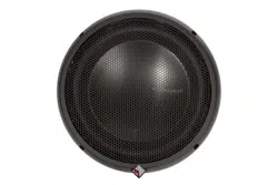
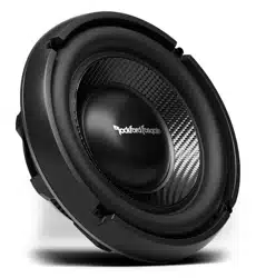
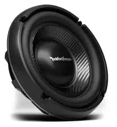
SUBWOOFERS
Serial Number: Date of Purchase:
Rockford Corporation offers a limited warranty on Rockford Fosgate products on the following terms:
Length of Warranty
Speakers – 1 Year. Any Factory Refurbished Product – 90 days (receipt required)
What is Covered
This warranty applies only to Rockford Fosgate products sold to consumers by Authorized Rockford Fosgate
Dealers in the United States of America or its possessions. Product purchased by consumers from an
Authorized Rockford Fosgate Dealer in another country are covered only by that country’s Distributor and
not by Rockford Corporation.
Who is Covered
This warranty covers only the original purchaser of Rockford product purchased from an Authorized
Rockford Fosgate Dealer in the United States. In order to receive service, the purchaser must provide
Rockford with a copy of the receipt stating the customer name, dealer name, product purchased and date of
purchase. Products found to be defective during the warranty period will be repaired or replaced
(with a product deemed to be equivalent) at Rockford's discretion.
What is Not Covered
1.Damage caused by accident, abuse, improper operations, water, theft, shipping
2.Any cost or expense related to the removal or reinstallation of product
3.Service performed by anyone other than Rockford or an Authorized Rockford Fosgate Service Center
4.Any product which has had the serial number defaced, altered,or removed
5.Subsequent damage to other components
6.Any product purchased outside the U.S.
7.Any product not purchased from an Author
ized Rockford Fosgate Dealer
Limit on Implied Warranties
Any implied warranties including warranties of fitness for use and merchantability are limited in duration to the
period of the express warranty set forth above.Some states do not allow limitations on the length of an implied
warranty,so this limitation may not apply.No person is authorized to assume for Rockford Fosgate any other
liability in connection with the sale of the product.
How to Obtain Service
Contact the Authorized Rockford Fosgate Dealer you purchased this product from. If you need further
assistance, call 1-800-669-9899 for Rockford Customer Service.You must obtain an RA# (Return
Authorization number) to return any product to Rockford Fosgate.You are responsible for shipment
of product to Rockford.
EU Warranty
This product meets the current EU warranty requirements,see your Authorized dealer for details.
2010 Rockford Corporation.All rights reserved.
Rockford Fosgate, the Rockford Fosgate logo, and the POWER logo are either
registered trademarks or trademarks of Rockford Corporation.
L
IMITED
W
ARRANTY S
TATEMENT
Check our website for additional information and
updates on these products.
www.RockfordFosgate.com
10" 12" 15"
Dual 2-Ohm T1D210 T1D212 T1D215
Dual 4-Ohm T1D410 T1D412 T1D415
18/10 B.M.
1230-56541-01
Printed in China
2
BUILDING AN ENCLOSURE
To work properly, the walls of the enclosure must be rigid and not flex
when subjected to the high pressures generated by the speaker's
operation. For optimum performance, we recommend using 3/4" MDF
(Medium Density Fiberboard) and internal bracing.The enclosure should
be glued together and secured with nails or screws.
S
AFETY
PRACTICE SAFE SOUND™
Continuous exposure to sound pressure levels over 100dB may
cause permanent hearing loss. High powered auto sound systems
may produce sound pressure levels well over 130dB. Use common
sense and practice safe sound.
CARTON CONTENTS
• (1) Power DVC Subwoofer
• (1) Trim ring
• (4) Socket head trim ring screws
• (8) Socket head wood screws
• (1) Socket head driver bit
• (1) Installation & operation manual
VENTED ENCLOSURES
Vented enclosures vary only from the sealed enclosure in that a vent or
port is added to “tune” the enclosure.The enclosures recommended are
designed for great overall performance. Larger boxes tend to be easy to
tune to lower frequencies while medium and small boxes are easier
to tune to higher frequencies.The vented design is less linear in
response than the sealed box but with noticeably more output at
the tuning frequency.
Advantages of vented enclosures:
• Higher average output than sealed
• Tuning frequency can be easily adjusted by changing port length
• Deep bass response with lower power requirements
• Great for high output with limited power
R
ECOMMENDED
E
NCLOSURES
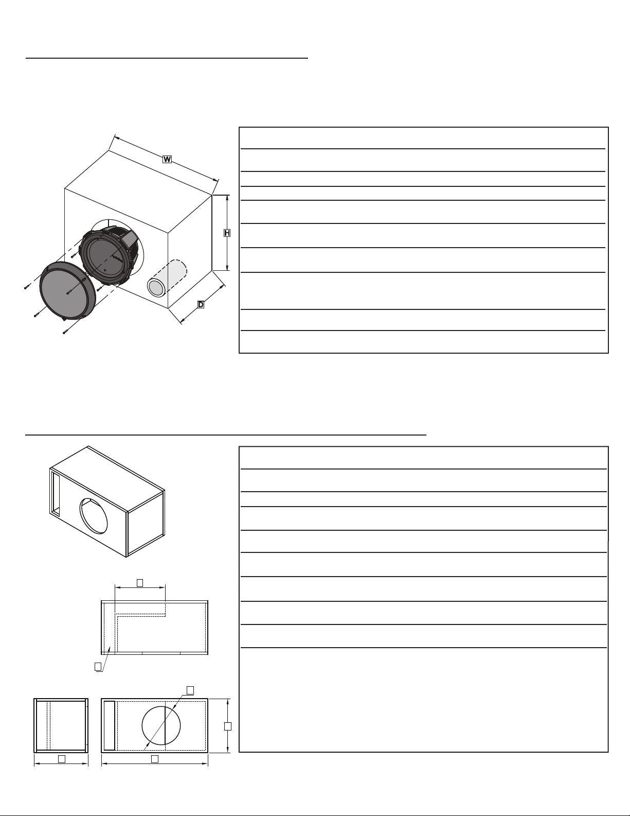
CALCULATING VOLUME
Calculating volume is merely a matter of measuring the dimensions in
inches and using the formula: H x W x D divided by 1728 (cubic feet).
See block below.
If two facing sides are of uneven length, add them together and divide by
two to take the average. Using this number will give you the volume
without the necessity of calculating the box in sections and adding the
sections together.The thickness of the baffle material reduces the internal
volume so this must be subtracted from the outside dimensions to
determine the internal volume.The speaker itself also reduces the
internal volume.The amount of air displaced by each model is listed on
the specification sheet and should also be subtracted from the gross
volume calculation.
Box Volume Height
"
x Width
"
x Depth
"
Divided by (cubic feet) 1728
This symbol with “CAUTION” is intended to
alert the user to the presence of important
instructions. Failure to heed the instructions
can result in injury or unit damage.
This symbol with “WARNING” is intended to
alert the user to the presence of important
instructions. Failure to heed the instructions
will result in severe injury or death.
CAUTION To prevent injury and damage to the unit, please
read and follow the instructions in this manual. We
want you to enjoy this system, not get a headache.
CAUTION If you feel unsure about installing this system
yourself, have it installed by a qualified Rockford
Fosgate technician.
CAUTION Before installation, disconnect the battery negative
(-) terminal to prevent damage to the unit, fire
adn/or possible injury.
DESIGN FEATURES
These woofers were designed for use primarily in small ported
enclosures. By utilizing the latest materials and construction techniques,
we are able to offer a speaker with high output at low frequencies while
requiring a minimum of operating space.
NOTE: Vb is the gross volume, which is the TOTAL internal volume, before any speaker and/or port displacement.
All external dimensions were based on the use of 3/4" (1.90cm) materials.
NOTE: When using enclosures other than recommended, call Technical Support for correct application.
V EENTED NCLOSURES
Specifications subject to change without notice
Specifications subject to change without notice
Number of ports noted in ( )
Optimum Vented(Ported) Enclosure Sizes
VENTED ENCLOSURES 10" 12" 15"
T1D210 / T1D410 T1D212 / T1D412 T1D215 / T1D415
V
b
- Internal Area cu. ft.
1.50 1.75 2.66
(49.55)(42.47)
)retiL(
SEALED ENCLOSURES 10" 12" 15"
T1D210 / T1D410 T1D212 / T1D412 T1D215 / T1D415
V
b
- Internal Area cu. ft.
0.75 1.25
(35.39)
2.25
(63.71)(21.24)
)retiL(
F
b
- Tuning Frequency (Hz)
40.0 40.0 32.0
F
3
- -3dB Point (Hz)
32.0 32.0 29.0
H - Height-inch
15.5 16.5 18.0
(41.91)(39.37)
)mc(
W - Width-inch
20.25 25.5 28.0
(64.77)(51.44)
)mc(
D - Depth-inch
12.5 10 12.0
(25.40)
(75.32)
(45.72)
(71.12)
(30.48)(31.75)
)mc(
P - Port Diameter and
Length-inch
(1) 4 x 11 (1) 4 x 9 (1) 4 x 10
(cm) (1) (10.16 x 27.94) (1) (10.16 x 22.86) (1) (10.16 x 25.40)
NOTE: The port shown can be placed on any face of the enclosure as long as the port ends are not obstructed.
NOTE: When using vented enclosures, for maximum reliability and power handling ensure that a subsonic or "infrasonic" filter is used so that
only usable low frequency signal is sent to the subwoofer.
3
Number of ports noted in ( )
VENTED ENCLOSURES 10" 12" 15"
T1D210 / T1D410 T1D212 / T1D412 T1D215 / T1D415
V
b
- Box Volume Net / Gross - cu. ft.
1.5 / 2.04 2.25 / 3.12 3.25 / 4.22
(63.71 / 88.35)
(42.48 / 57.77)
)retiL(
F
b
- Tuning Frequency (Hz) 38.0 40.0 38.0
B - Height-inch 13.5 15.25 18.0
(38.74)
(34.29)
)mc(
C - Depth-inch 13.5 15.25 17.0
(38.74)
(34.29)
)mc(
E - Length-inch
14.75 14.25 9.25
(36.20)
(37.47)
)mc(
F - Mounting Diameter-inch 9-1/8 11-1/4 13-15/16
(28.50)
(23.20)
)mc(
Baffle / Back-inch
Cut List
26 x 13.5 30 x 15.25 30 x 18
(76.20 x 38.74)
(66.04 x 34.29)
)mc(
Top / Bottom-inch 26 x 12 30 x 13.75 30 x 15.5
(76.20 x 34.93)
(66.04 x 30.48)
)mc(
Ends -inch 12 x 12 13.75 x 13.75 15.5 x 16.5
(34.93 x 34.93)
(30.48 x 30.48)
)mc(
Port -inch 14 x 12 - 10 x12 13.75 x 13.5 - 13.75 x 10.75 8.5 x 16.5 - 12.5 x 16.5
(34.93 x 34.29 - 34.93 x 27.31)
(35.56 x 30.48 - 25.4 x 30.48)
)mc(
A - Width-inch 26.0 30.0 30.0
(76.20)
(92.03 / 119.50)
(45.72)
(43.18)
(23.50)
(35.30)
(76.20 x 45.72)
(76.20 x 39.37)
(39.37 x 41.91)
(21.59 x 41.91 - 31.75 x 41.91)
(76.20)
(66.04)
)mc(
D - Port area and Length - inch
(1) 2 x 12.0 x 25.5 (1) 3 x 13.75 x 25.75 (1) 3 x 16.5 x 22.5
(cm) (1) (5.08 x 30.48 x 64.77) (1) (7.62 x 34.93 x 65.41) (1) (7.62 x 41.91 x 57.15)
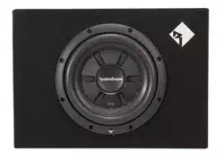
“ H
IGH
O
UTPUT
” S
LOT
L
OADED
E
NCLOSURES
E
A
B
C
F
D
3/4" MDF
D
W
H
4
Specifications subject to change without notice
"21 "51"01 POWER T1-DVC
T1D210 / T1D410 T1D212 / T1D412 T1D215 / T1D415
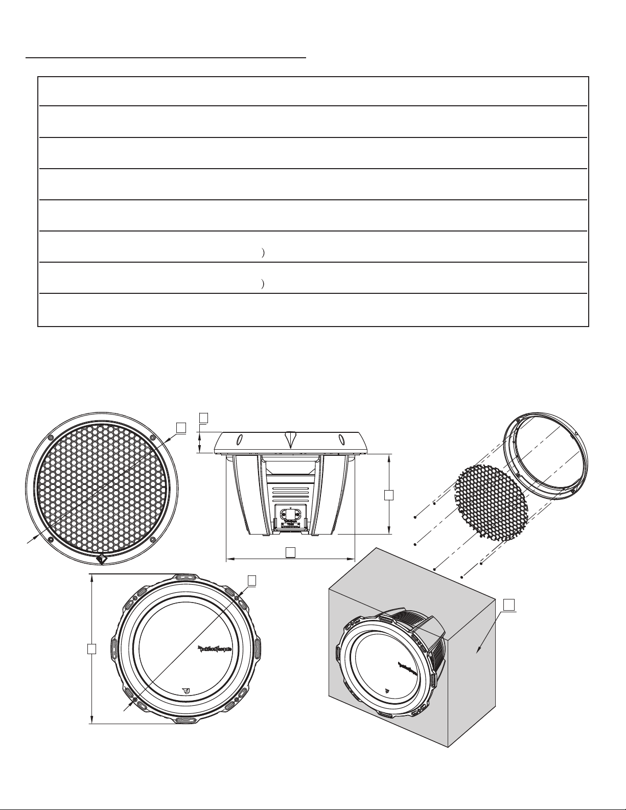
A - Trim Ring Diameter-inch 11.02 13.07 16.22
(33.2)(28.0))mc(
B 1.79 2.361.79hcni-thgieH gniR mirT-
(4.55)(4.55))mc(
C - Mounting Diameter-inch 9-1/8 11-1/4 13-15/16
(28.50)(23.20))mc(
D - Mounting Depth-inch 6-1/2 6-7/8 8-25/64
(17.46)(16.51))mc(
E - Overall Diameter-inch 10.79 12.84 15.91
(32.60)(27.40)mc(
F - Screw Hole Diameter-inch 10.16 12.29 14.96
(31.20)(25.80)mc(
G - Speaker Displacement - cu. ft. 0.203 0.308 0.547
(8.73)
(41.2)
(6.00)
(35.30)
(21.30)
(40.40)
(38.0)
(15.5)(5.75))retiL(
PHYSICAL DIMENSIONS
D
B
C
E
F
G
A
5
Model - Power DVC T1D210 T1D410 T1D212 T1D412 T1D215 T1D415
Nominal Impedance (ohms) 2Ω (2) 4Ω (2) 2Ω (2) 4Ω (2) 2Ω (2) 4Ω (2)
Voice Coil Diameter-inch (mm) 3 (75.5) 3 (75.5) 3 (75.5) 3 (75.5) 3 (75.5) 3 (75.5)
33.031.5 27.026.336.034.5)zH( SF
0.610.52 0.510.430.65.540STQ
VAS-cu.ft. (liter) 0.54 (15.4) 0.55 (15.7) 1.55 (43.8) 1.53 (43.2) 3.60 (102) 3.60 (102)
Xmax-inch (mm) 0.65 (16.4) 0.65 (16.4) 0.65 (16.4) 0.65 (16.4) 0.65 (16.4) 0.65 (16.4)
SPL (dB @ 1w/1m) 83.0 83.0 86.0 86.0 88.0 88.0
Power Handling (RMS) 600 600 800 800 1000 1000
Power Handling (Max) 1200 1200 1600 1600 2000 2000
Mounting Dia.-inch (mm) 9-1/8 (232.0) 9-1/8 (232.0) 11-1/4 (285.0) 11-1/4 (285.0) 13-15/16 (353.0) 13-15/16 (353.0)
Mounting Depth-inch (mm) 6-1/2 (16.51) 6-1/2 (16.51) 6-7/8 (17.46) 6-7/8 (17.46) 8-25/64 (213.0) 8-25/64 (213.0)
Speaker Dis.-cu. ft. (liter) 0.203 (5.75) 0.203 (5.75) 0.308 (8.73) 0.308 (8.73) 0.547 (15.5) 0.547 (15.5)
Specifications subject to change without notice
SPECIFICATIONS
Sealed Box Vol.-cu.ft.(liter) 0.75 (21.24) 0.75 (21.24) 1.25 (35.39) 1.25 (35.39) 2.25 (63.71) 2.25 (63.71)
Vented Box Vol.-cu.ft.(liter) 1.5 (42.47) 1.5 (42.47) 1.75 (49.55) 1.75 (49.55) 2.66 (75.32) 2.66 (75.32)
Port Diameter & Length (in.) (1) 4 x 11 (1) 4 x 11 (1) 4 x 9 (1) 4 x 9 (1) 4 x 10 (1) 4 x 10
Port Diameter & Length (cm) (1) 10.16 x 27.94 (1) 10.16 x 27.94 (1) 10.16 x 22.86 (1) 10.16 x 22.86 (1) 10.16 x 25.40 (1) 10.16 x 25.40
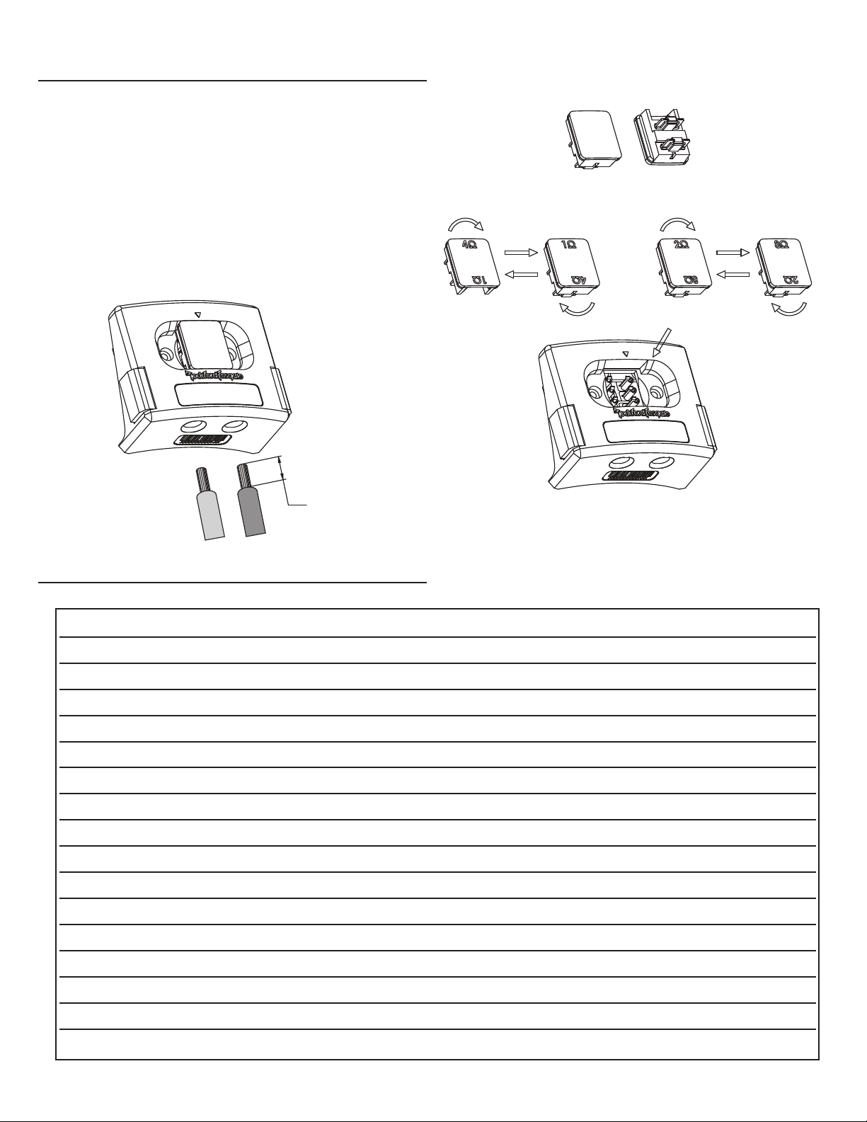
Strip 5/8"
(0.625)(16 mm)
T1D210
T1D212 / T1D215
T1D410
T1D412 / T1D415
TERMINAL
Rockford's proprietary SWIFT™ Terminal provides simple convenient
selection of nominal impedance load of the dual voice coil sub-woofer.
The removable impedance selection jumper also provides fused
protection in severe overload conditions and should only be replaced by
an authorized dealer.
As per the illustration, by inverting the center plug the dual voice coil's
are connected in either a "series of parallel" configuration allowing for
convenient configuration for optimal amplifier loading. Please make sure
that this center plug is securely fitted. This should only be done by an
authorized Rockford dealer to insure the system is properly configured.
NOTE: Sub also includes non fused jumper.
Français
MISE EN GARDE :avant d'entamer l'installation, déconnectez la
broche négative (-) de la batterie pour éviter tout risque de blessures,
d’incendie ou de dommages à l'appareil.
Enceintes recommandées
Ce manuel décrit deux types particuliers d'enceintes aux performances tout à fait
distinctes.Cette section vous permettra de décider celui qui vous conviendra le
mieux.
Enceintes Étanches
Les enceintes étanches sont les plus faciles à fabriquer. À cet égard, la chose la plus
importante dans leur fabrication est de vous assurer qu'elles sont vraiment
hermétiques.Appliquez de la colle et un produit d'étanchéité sur tous les joints
pour solidifier l'ensemble et empêcher toute fuite d'air. Le volume du caisson influe
directement sur la performance
du haut-parleur. Les enceintes de plus grande
dimension délivrent une réponse uniforme en fréquence avec des graves profonds
alors que les enceintes plus petites ont une courbe de réponse plus prononcée et
un rendement généralement supérieur pour un niveau de pression acoustique plus
élevé.
Avantage des enceintes étanches :
• Petites enceintes
• Réponse linéaire (uniforme)
• Pas de bruit d'évent
• Puissance élevée sur toutes les fréquences
• Excellentes en ce qui concerne la qualité du son
Enceintes À Évent
Les enceintes à évent se distinguent des enceintes étanches du fait qu'on y ajoute
un évent ou port pour les « accorder ».Les enceintes recommandées sont
conçues pour offrir d'excellentes performances. Il est généralement plus facile
d'accorder les caissons plus grands pour l'obtenti
on de basses fréquences et les
caissons moyens et petits pour des fréquences plus élevées. Les enceintes à évent
ont une réponse moins linéaire que les enceintes étanches mais dégagent
nettement plus de puissance à la fréquence d'accord.
Avantages des enceintes à évent :
• Rendement moyen supérieur par rapport aux modèles étanches
• La fréquence d'accord peut être facilement réglée en changeant la longueur
de l'évent
• Reproduction profonde des basses avec une puissance d'entrée moindre
• Excellent choix pour un rendement élevé à faible puissance d'entrée
Construire Un Caisson
Pour fonctionner convenablement les parois du caisson doivent être rigides
lorsqu'elles sont soumises aux hautes pressions dues au fonctionnement du
haut-parleur. Nous vous recommandons d'utiliser des panneaux de bois aggloméré
à haute ou moyenne densité de part
icules de type “MDF”. Ces panneaux sont
disponibles dans la plupart des magasins de bricolage. Pour un caisson de grand
volume il est recommandé de placer des renforts à l'intérieur du caisson.Les
différents côtés devront être collés (colle à bois) et vissés (ou éventuellement
cloués). Il est recommandé de mettre un joint de silicone dans les arêtes internes
du caisson afin d'éviter les fuites d'air.
Calcu du Volume
On calcule le volume en mesurant la dimension de chaque côté et en utilisant la
formule suivante:
Si les due côtés qui se font face n'ont pas la même longueur, additionnez les et
divisez le résultat par deux pour obtenir la moyenne des deux longueurs. Utilisez
le nombre ainsi obtenu dans la
formule pour déterminer le litrage. Cette méthode
permet d'obtenir le volume du caisson sans devoir faire de calculs compliqués de
section de volume.L'épaisseur du matériau dont est fait le caisson réduit le volume
interne de celui-ci. Lorsqu'on mesure les côtés du caisson il ne faut donc pas
oublier d'oter des mesures l'epaisseur du matériau. Le haut-parleur lui-même
diminue le volume interne du caisson.Le volume d'air déplacé par chaque modèle
de haut-parleur est repris dans les spécifications techniques et doit également être
soustrait du volume total.
Configuration du câblage
En variant la configuration du câblage de vos haut-parleurs,vous pouvez créer
une charge d'impédance correspondant à votre système.La modification des
configurations de câb
lage offre tout un choix d'options en ce qui concerne la
charge d'impédance. Les câblages série, parallèle, ou série/parallèle sont des
techniques permettant de câbler les haut-parleurs de manière à produire des
charges différentes. La configuration série consiste à câbler les haut-parleurs à
la chaîne,bout à bout. La configuration parallèle utilise deux ou plusieurs
haut-parleurs branchés sur des bornes communes.La configuration série/parallèle
combine les deux techniques. Choisissez le schéma ci-dessous qui correspond au
nombre de haut-parleurs de graves et à l'impédance de votre ampli.
Filtres de subwoofer
On distingue deux types de filtres opérationnels : passif et actif. Les filtres passifs
(bobines ou inducteurs) sont placés sur les fils de haut-parleur
, entre l'ampli et le
haut-parleur. Un filtre actif est un filtre électronique qui sépare le signal audio
envoyé à différents amplis. Pour obtenir une performance optimale du subwoofer,
nous recommandons l'utilisation d'un filtre actif passe-bas 80-100 Hz à 12
dB/octave.
Español
PRECAUCIÓN: Antes de la instalación,desconecte el terminal
negativo de la batería (-) para prevenir daño a la unidad, incendio y/o
posibles lesiones.
Cajas recomendadas
Este manual delinea dos tipos específicos de cajas que producen rendimientos
inconfundiblemente diferentes.Esta sección es para ayudarle a decidir cuál tipo es
el mejor para su aplicación.
Cajas CERRADAS
Las cajas cerradas son las más fáciles de hacer. La parte más importante de la
construcción de una caja cerrada es garantizar su hermetismo. El uso de pegante y
algún tipo de sellador en todos los bordes garantizará una construcción sólida y
evitará fugas de aire. El volumen de la caja impacta directamente el rendimiento
del altavoz. Las cajas más grandes ofrecen una respuesta más plana y un bajo más
profundo, mientras que las más pequeñas ofrecen un incremento en la curva de
respuesta y generalmente una salida mayor, para un mayor NPS.
Ventajas de las cajas cerradas:
• Cajas pequeñas
• Respuesta lineal (plana)
• No hay ruido del orificio
• Capacidad de alta potencia en todas las frecuencias
• Excelentes para la calidad del sonido
Cajas con Orificios
Las cajas con orificios sólo se diferencian de las cerradas en que se les hace un
orificio para "sintonizarlas." Las cajas recomendadas son diseñadas para un gran
rendimiento general.Las cajas grandes tienden a ser fáciles de sintonizar en las
frecuencias graves, mientras que medianas y pequeñas son más fáciles de sintonizar
en las frecuencias más altas. El diseño con orificios es de una respuesta menos
lineal que el de la caja cerrada, pero tiene una salida notablemente mayor en la
frecuencia de sintonización.
Ventajas de las cajas con orificios:
• Un promedio de salida mayor que las cerradas
• La frecuencia de sintonización se ajusta fácilmente al cambiar la longitud del
orificio
Volume du caisson Hauteur (cm) x Longueur (cm) x Largeur (cm)
Divisé près (Litres) 1000
6
PRATIQUEZ UNE ÉCOUTE SANS RISQUES
MD
Une exposition continue à des niveaux de pression acoustique supérieurs
à 100 dB peut causer une perte d'acuité auditive permanente. Les
systèmes audio de forte puissance pour auto peuvent produire des
niveaux de pression acoustique bien au-delà de 130 dB. Faites preuve de
bon sens et pratiquez une écoute sans risques
PRACTIQUE EL SONIDO SEGURO
El contacto continuo con niveles de presión de sonido superiores a 100 dB
puede causar la pérdida permanente de la audición. Los sistemas de sonido para
automóviles de alta potencia pueden producir niveles de presión de sonido
superiores a los 130 dB. Use su sentido común y practique el sonido seguro.
• Respuesta de bajo profundo con menos exigencia de potencia
• Fabulosas para salida alta con potencia limitada
Construcción de una caja
Para un buen funcionamiento las paredes de la caja deben ser rigidas y no
se deben doblar cuando sean sometidas a la gran presión que ejerce el
funcionamiento del altavoz. Recomendamos usar madera comprimida de mediana
densidad, de 1.9 cm o fibra de media densidad. Si la caja es muy grande es
necessario reforzarla internamente. Las juntas deben ser encoladas y aseguradas
con tornillos o grapas.Internamente los bordes deben ser sellados con silicona
para prevenir las fugas de aire. La cola para madera es la mejor opción.
Cálculo de Volúmenes
Para calcular el volumen sólo se han de medir las dimensiones en centímetros y
aplicar
la fórmula:
Si dos caras opuestas son de diferente tamaño, súmelas y divida el total por
dos para obtener el promedio. Usando esta técnica se ahorrara el cálculo por
secciones. El espesor del material con que está construida la caja reduce el
volumen interno,de manera que ha de restarse de las dimensiones exteriores para
determinar el volumen interior. La cantidad de aire que ocupa cada modelo viene
especificado en la hoja de características y también debe sustraerse para obtener
el volumen neto interior.
Configuraciones del cableado
Al variar la configuración del cableado de los altavoces, usted puede crear una
impedancia de carga que iguale a su sistema. La alteración de la configuración de
los cables da una gama de opciones para impedancia de carga
. Las configuraciones
en serie, paralela o en serie-paralela son técnicas diferentes para el cableado de los
altavoces que ofrecen cargas diferentes. La configuración en serie es un método en
cadena en el que los altavoces se conectan de punta a punta. La configuración
paralela usa dos o más altavoces conectados a lo largo de terminales en común. La
configuración en serie-paralela combina ambas técnicas. Escoja el diagrama que
corresponda al número de altavoces para sonidos graves y la impedancia de su
amplificador
Filtros de Transición del altavoz para sonidos graves
(Subwoofer X-Over)
Hay dos tipos funcionales de filtros de transición,pasivos y activos. Los pasivos
(bobinas o inductores) se conectan a los cables de
l altavoz, entre el amplificador y
el altavoz.Un filtro de transición activo es un filtro electrónico que separa la señal
de audio alimentada a diferentes amplificadores. Para un rendimiento óptimo del
altavoz para sonidos graves, recomendamos el uso de un filtro de transición activo
de 80-100Hz,paso bajo a 12dB/octava.
Deutsch
VORSICHT: Entfernen Sie vor dem Einbau den negative Batteriepol,
um Schäden am Gerät, Feuer bzw. mögliche Verletzungen zu vermeiden.
Empfohlene Gehäuse
Diese Anleitung beschreibt zwei spezifische Typen von Gehäusen,die grundsätzlich
verschiedene Performancemerkmale bieten. Dieser Abschnitt soll Ihnen dabei
helfen zu entscheiden, welcher der beste Typ für Ihre Anwendung ist.
Geschlossene Gehäuse
Geschlossene Gehäuse lassen sich am leichtesten bauen. Der wichtigste Aspekt
beim Bau eines geschlossenen Gehäuses ist zu gewährleisten, dass es luftdicht ist.
Die Verwendung von Klebstoff und anderen Dichtungsmitteln an allen Fugen
gewährleistet eine solide Konstruktion und verhindert Luftverlust. Das
Gehäusevolumen wirkt sich unmittelbar auf die Performance des Lautsprechers
aus. Größere Gehäuse bieten eine flachere Reaktion und tiefere Bässe, wohingegen
kleinere Gehäuse eine Abweichung in der Reaktionskurve bieten und im
Allgemeinen durch höhere Leistung zu einem höheren Schalldruckpegel führen.
Vorteile von geschlossenen Gehäusen:
• Kleine Gehäuse
• Lineare (flache) Reaktion
• Keine Öffnungsgeräusche
• Hohe Nennbelastbarkeit in allen Freque
nzbereichen
• Ausgezeichnete Klangqualität
Belüftete Gehäuse
Belüftete Gehäuse unterscheiden sich von geschlossenen Gehäusen nur in sofern,
als dass ein Luftschlitz bzw. eine Öffnung hinzugefügt wird, um das Gehäuse zu
„stimmen“. Die empfohlenen Gehäuse sind für hervorragende Gesamtperformance
konstruiert. Größere Gehäuse lassen sich in der Regel leichter auf niedrigere
Frequenzen abstimmen, wohingegen sich mittlere und kleine Gehäuse leichter auf
höhere Frequenzen abstimmen lassen. Das belüftete Design zeigt eine weniger
lineare Reaktion als das geschlossene Gehäuse, erbringt jedoch eine feststellbar
höhere Leistung auf der abgestimmten
Frequenz.
Vorteile von belüfteten Gehäusen:
• Höhere Durchschnittsleistung als geschlossene Gehäuse
• Abstimmfrequenz kann leicht durch Änderung der Öffnungslänge angepasst
werden
• Tiefes Bassverhalten bei geringerem Kraftbedarf
• Gut geeignet für hohe Leistung bei beschränkter Kraft
Bau des Gehäuses
Um ordnungsgemäß zu funktionieren,müssen die Gehäusewände steif sein und
dürfen nicht nachgeben,wenn sie dem hohen Druck ausgesetzt sind,der bei Betrieb
des Lautsprechers entsteht.Für optimale Performance empfehlen wir Faserplatte
mittlerer Dichte (Stärke ca.1,9 cm) und interne Aussteifungen. Das Gehäuse wird
verleimt und mit Nägeln oder Schrauben befestigt. Da Faserplatte luftdurchlässig ist,
wird geraten,das Gehäuse von außen mit Polyurethan zu behandeln.
Berechnung des Volumens
Zur Berechnung des Volumens einfach die Maße feststellen und folgende Formel
anwenden:
Sind zwei gegenüber liegende Seiten ungleich lang, die Durchschnittslänge der
beiden Seiten berechnen.Das Volumen lässt sich mithilfe dieser Zahl berechnen,
ohne das Gehäuse in Abschnitten berechnen zu müssen. Die Stärke des
Resonanzwandmaterials reduziert das Innenvolumen und muss daher zur
Feststellung des Innenvolumens vom Außenvolumen subtrahiert werden. Der
Lautsprecher selbst reduziert das Innenvolumen ebenfalls. Die Luftverdrängung für
jedes Modell ist unter Technische Daten aufgeführt und muss bei der
Gesamtkalkulation des Volumens ebenfalls subtrahiert werden.
Verkabelungskonfigurationen
Durch Veränderung der Verkabelungskonfiguration Ihrer Lautsprecher können Sie
eine Impedanzlast herstellen, die Ih
rem System entspricht. Bietet die Veränderung
der Verkabelungskonfigurationen eine Reihe von Optionen für die Impedanzlast.
Reihen-, Parallel- oder Reihen-Parallel-Verkabelungen sind verschiedene Techniken
für die Verkabelung von Lautsprechern, die unterschiedliche Belastungen bieten. Die
Reihenkonfiguration ist eine Reihenmethode,bei der die Lautsprecher von Ende zu
Ende verkabelt werden.Die Parallelkonfiguration verwendet mindestens zwei
Lautsprecher, die über gemeinsame Anschlüsse verkabelt werden. Die Reihen-
Parallel-Konfiguration kombiniert beide Techniken.Wählen Sie das nachfolgende
Verkabelungsdiagramm aus, das der Zahl an Tieftönern und der Impedanz Ihres
Verstärkers entspricht.
Subwoofer-Crossover
Es gibt zwei Betriebstypen für Crossover, und zwar passive und aktive. Passive
Crossover (Spulen oder Induktoren) werden auf den Lautsprecherkabeln zwischen
Verstärker und Lautsprecher platziert. Ein aktives Crossover ist ein elektronischer
Filter, der das Audiosignal trennt, das verschiedenen Verstärkern zugeführt wird.
Zur optimalen Subwoofer-Performance empfehlen wir die Verwendung von aktiven
80-100 Hz-Niedrigpass-Crossovern bei 12 dB/Oktav.
7
PRAKTIZIEREN SIE SICHEREN SOUND
Fortgesetzte Geräuschdruckpegel von über 100 dB können beim Menschen zu
permanentem Hörverlust führen.Leistungsstarke Autosoundsysteme können
Geräuschdruckpegel erzeugen,die weit über 130 dB liegen. Bitte wenden Sie
gesunden Menschenverstand an und praktizieren Sie sicheren Sound.
Volumen du la caja Alto(cm) x Ancho(cm) x Profundidad(cm)
Dividido por (en litros) 1000
Gehäuse-Volumen Höhe (cm) x Breite (cm) x Tiefe (cm)
Vorbei geteilt (Liter) 1000
8
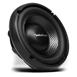
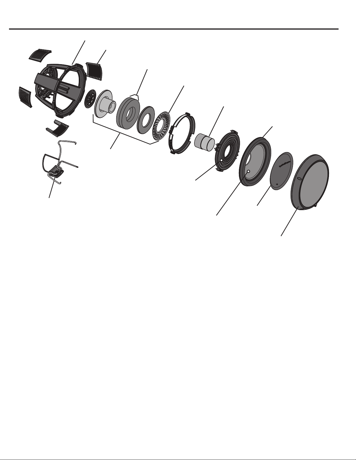
FEATURES
•
Hard anodized aluminum dust cap.
•
Kevlar fiber reinforced semi-pressed paper cone.
•
Tear & fatigue resistant poly-cotton spider with integrated stitched balanced leads.
•
High durability VAST™ Santoprene™ surround.
• Ultra-High temp aluminum voice coil with spun-laced Nomex™ insulating reinforcement collar.
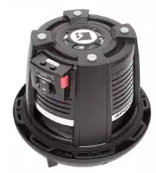
•
Optimized motor magnetics with extended vented pole and bumped backplate.
•
Double stack ferrite magnet structure.
•
Proprietary spider cooling vents.
•
Multi-point high-temp/high-strength neck joint bonding technique.
•
Rigid die-cast aluminum frame.
•
Proprietary SWIFT™ terminal (Selectable Woofer Impedance Fused Termination)
•
Proprietary SWIFT™ Terminal with balance 10 gauge lead-in wire connections.
•
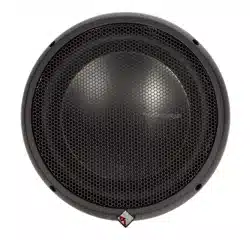
Removable and reversible screw concealing ring.
•
IDHS™ Inductive Damping Heat Sink.
Double stack ferrite magnet structure
IDHS™ Inductive Damping Heat Sink
Ultra-High temp aluminum voice coil
with spun-laced Nomex™ insulating
reinforcement collar
Proprietary spider cooling vents
Tear and fatigue resistant
poly-cotton spider with
integrated stitched balanced leads
Kevlar fiber reinforced
semi-pressed paper cone
High durability
VAST™ Santoprene™
surround
Optimized motor magnetics
with extended vented pole
and bumped backplate
Rigid die-cast aluminum frame
Proprietary SWIFT™ Terminal
with balance 10 gauge lead-in
wire connections
Hard anodized
aluminum
dust cap
Removable and reversible
screw concealing ring