Loading ...
Loading ...
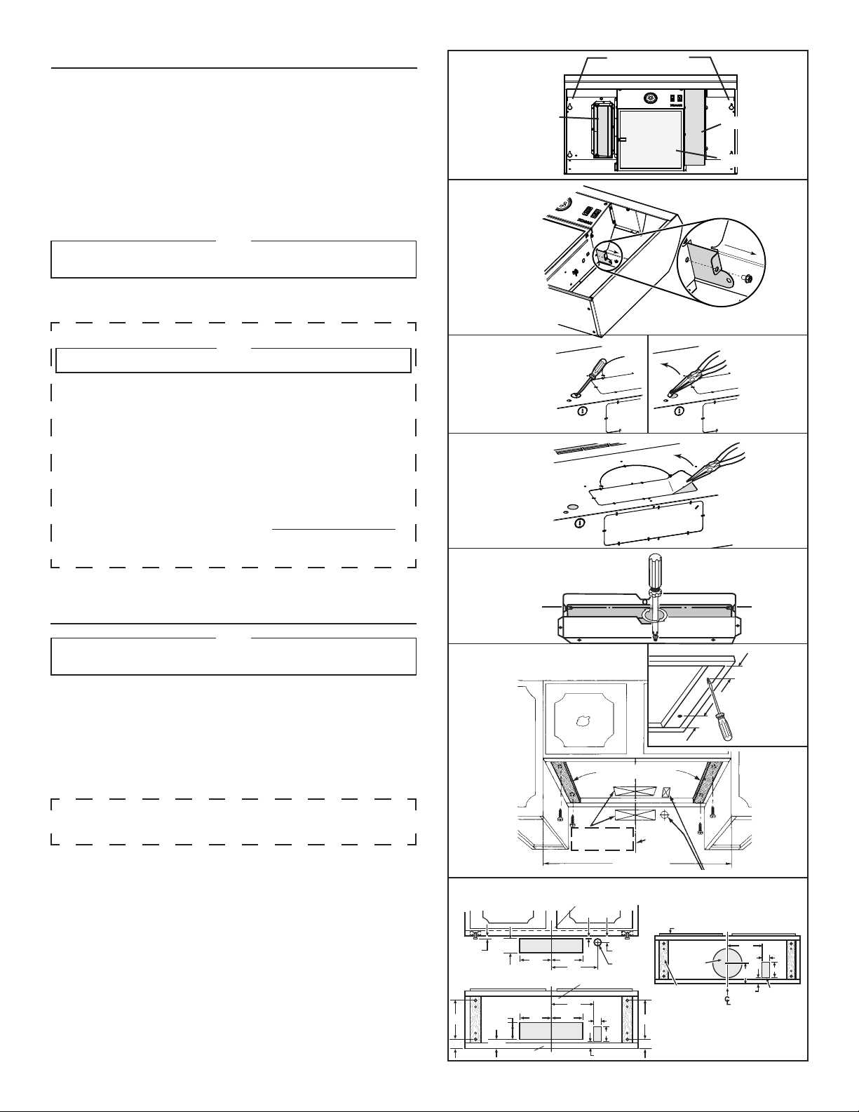
1. Unpack hood and check contents. You should have:
1 - Aluminum filter
1 - 3¼” x 10” Damper/duct connector
(mounted inside of hood for shipping only) (save the screws)
1 - LED bulb with GU10 base.
2. Remove wiring box cover. Under cover find the parts bag containing
loose hardware.
For non-ducted installation only
3. For non-ducted installation, remove the trap door retaining screw from
inside the hood, then pull the grille trap door out of the hood and discard.
(FIG. 3)
NOTE
The grille on front of hood must be open and visible for hood
to operate in non-ducted mode.
4. Remove either top or rear electrical knockout depending upon whether
wiring will enter hood from wall or cabinet. (FIG. 4)
PREPARING THE RANGE HOOD
DUCTED INSTALLATION ONLY
NOTE
The trap door must NOT be removed to function in ducted mode.
5. Remove appropriate duct knockout on hood by inserting screwdriver
into edge of knockout and breaking tabs holding knockout to hood.
Peel knockout back with pliers. (FIG. 5)
6. For 3¼” x 10” ducting only: Fit damper/duct connector over opening
and secure in place using screws previously removed in PREPARING
THE HOOD section (FIG. 6)
Hinge pins and damper/duct connector should be toward top of hood
for ducting through wall or toward back of hood for ducting through
cabinet above hood. Seal joint between damper/duct connector and
hood with duct tape.
7. 7” round ducted discharge only: Install, between 2 duct sections, a
7” round damper (purchase separately). Damper flap must open
freely in direction of air flow (away from range hood).
PREPARING THE INSTALLATION LOCATION
NOTE
MOUNT HOOD SO THAT BOTTOM OF HOOD IS 20”-25” ABOVE
COOKING SURFACE.
OMIT STEP 8 if range hood will be installed under cabinets with flush
bottom.
8. (For installation on recessed bottom cabinets only.) Attach a wood filler
strip at each side of recessed area under cabinet. (Use two 1” x 2” strips
cut to length.) If recess is more than 1” use thicker strips. Attach strips
with 1¼” screws about 3” from each end. See FIG. 7.
9. Measure and mark the following (FIGS. 7 & 8):
a) Electrical line opening
b) Duct opening
10. Drill four pilot holes in corners of marked duct opening as shown and cut
opening with saber saw or keyhole saw.
11. Use 1¼” drill bit to drill opening for electrical connection in wall or
cabinet.
12. Hold hood up against cabinet bottom and trace keyhole slots onto
cabinet bottom or filler strips.
13. Screw the four supplied 7/8” wood screws for mounting the hood into the
exact center of the narrow end of the keyhole slots marked underneath
the cabinet. Allow 3/8” of the screws to project, so the hood can be fitted
into place.
CUT STRIPS TO FIT
CENTER LINE
WIDTH OF
RANGE HOOD
ELECTRICAL WIRING OPENING
DUCT OPENINGS
CABINET FRONT
VERTICAL DUCTING AND WIRING
(Through cabinet bottom)
CABINET BOTTOM
BACK WALL
HORIZONTAL DUCTING
AND WIRING (Through wall)
3¼” x 10” DUCT
7” ROUND DUCT
3"
3"
8” DIA.
ACCESS HOLE
WOOD SHIMS
(recessed-bottom
cabinets only)
ELECTRICAL
ACCESS HOLE
(in cabinet bottom)
CABINET BOTTOM
5”
CABINET FRONT
HM0014A
7½”
5¼” 5¼”
1/8”
3/8” 3/4”
1½”
9”
5¼” 5¼”
6¾”
1/2”
1/
8
”
4½”
1½”
9”
3¾”
Ø 1½”
1½”
3”
6¾”
1/2”
1½”
3”
FIG. 2
FIG. 3
FIG. 4
FIG. 5
FIG. 6
FIG. 7
FIG. 8
- 3 -
KEYHOLE SLOTS (4)
ALUMINUM FILTER
DAMPER/DUCT CONNECTOR
WIRING BOX COVER
Loading ...
Loading ...
Loading ...