
www.klarstein.com
DELOREAN
Dunstabzugshaube
Range Hood
Campana extractora
Hotte aspirante
Cappa aspirante
10033707 10033708


3
DE
Sehr geehrter Kunde,
wir gratulieren Ihnen zum Erwerb Ihres Gerätes. Lesen Sie
die folgenden Hinweise sorgfältig durch und befolgen Sie
diese, um möglichen Schäden vorzubeugen. Für Schäden,
die durch Missachtung der Hinweise und unsachgemäßen
Gebrauch entstehen, übernehmen wir keine Haftung. Scannen
Sie den folgenden QR-Code, um Zugriff auf die aktuellste
Bedienungsanleitung und weitere Informationen rund um das
Produkt zu erhalten:
INHALTSVERZEICHNIS
Technische Daten3
Sicherheitshinweise4
Hinweise zum Umweltschutz6
Geräteübersicht7
Abmessungen und Abstände9
Installation11
Bedienfeld16
Reinigung und Wartung17
Fehlersuche und Fehlerbehebung19
Hinweise zur Entsorgung21
Hersteller & Importeur (UK)21
Produktdatenblatt22
TECHNISCHE DATEN
Artikelnummer 10033707, 10033708
Stromversorgung 220-240 V ~ 50/60 Hz
Hinweis: Zu dieser Dunstabzugshaube können Sie unter der Artikelnummer
XXXXXXXX zusätzlich einen Aktivkohlelter erwerben. Besuchen Sie dafür unsere
Webseite: www.elektronik-star.de
English 25
Español 47
Français 69
Italiano 91

4
DE
SICHERHEITSHINWEISE
• Lesen Sie sich alle Hinweise vor der Benutzung sorgfältig durch und bewahren Sie
die Bedienungsanleitung zum späteren Nachschlagen gut auf.
• Die Montagearbeiten dürfen nur von einer Elektrofachkraft oder einer qualizierten
Person durchgeführt werden. Bevor Sie die Dunstabzugshaube verwenden, stellen
Sie sicher, dass die Spannung (V) und die auf der Dunstabzugshaube angegebene
Frequenz (Hz) der Spannung und Frequenz der Stromversorgung in Ihrem Haushalt
entsprechen.
• Für Schäden, die durch unsachgemäßen Gebrauch und unsachgemäße Installation
entstehen, übernehmen wir keine Haftung.
• Kinder unter 8 Jahren dürfen die Dunstabzugshaube nicht benutzen.
• Das Gerät ist nicht für den kommerziellen Gebrauch, sondern nur für Gebrauch im
Haushalt und in ähnlichen Umgebungen vorgesehen.
• Reinigen Sie das Gerät und den Filter regelmäßig, damit das Gerät immer efzient
arbeitet.
• Ziehen Sie vor der Reinigung immer den Stecker aus der Steckdose.
• Reinigen Sie das Gerät genau wie in der Bedienungsanleitung angegeben.
• Verwenden Sie unter der Abzugshaube kein offenes Feuer.
• Falls das Gerät nicht normal funktioniert, wenden Sie sich an den Hersteller oder
einen Fachbetrieb.
• Kinder ab 8 Jahren, psychisch, sensorisch und körperlich eingeschränkte Menschen
dürfen das Gerät nur benutzen, wenn sie vorher von einer für sie verantwortlichen
Aufsichtsperson ausführlich mit den Funktionen und den Sicherheitsvorkehrungen
vertraut gemacht wurden und die damit verbundenen Risiken verstehen.
• Falls das Netzkabel oder der Stecker beschädigt sind, müssen sie vom Hersteller,
einem autorisierten Fachbetrieb oder einer ähnlich qualizierten Person ersetzt
werden.
• Wenn die Dunstabzugshaube mit Herden verwendet wird, die Gas oder andere
Brennstoffe verbrennen, muss eine ausreichende Belüftung des Raumes vorhanden
sein.
• Flambieren Sie nicht unter der Abzugshaube.
• Achtung: Die Geräteoberäche kann während des Betriebs heiß werden.
Wichtige Hinweise zur Installation
• Die Luft darf nicht in einen Abzug abgeleitet werden, der zum Absaugen von
Rauchgasen von Gas- oder anderen Brennstoffen verwendet wird (gilt nicht für
Geräte, die nur die Luft in den Raum zurückführen).
• Beachten Sie alle regionalen Vorschriften zum Einbau von Entlüftungsanlagen.
5
DE
Wichtige Hinweise zum Abluftbetrieb
WARNUNG
Vergiftungsgefahr durch zurückgesaugte Abgase! Betreiben Sie das
Gerät nicht im Abluftbetrieb, wenn es zusammen mit einer
raumluftabhängigen Feuerstätte betrieben wird und keine
ausreichende Luftzirkulation garantiert wird.
Raumluftabhängige Feuerstätten wie Gas-, Öl-, Holz- oder Kohleheizungen, Boiler oder
Durchlauferhitzer beziehen die Luft aus dem Raum und führen sie durch ein Abluftrohr
oder einen Kamin ins Freie. Im Abluftbetrieb wird der Küche und den benachbarten
Räumen Luft entzogen. Ohne ausreichende Zuluft entsteht ein Unterdruck. Giftige
Gase aus dem Kamin oder Abluftrohr können dabei in die Wohnräume zurückgesaugt
werden.
• Achten Sie darauf, dass ausreichend Frischluftzufuhr garantiert ist und die Luft
zirkulieren kann.
• Ein Zuluft-/Abluftmauerkasten reicht nicht aus, um die Einhaltung des Grenzwertes
sicherzustellen.
Ein gefahrloser Betrieb ist nur dann möglich, wenn der Unterdruck am Standort der
Feuerstätte 4 Pa (0,04 mbar) nicht überschreitet. Das erreichen Sie, wenn durch nicht-
verschließbare Öffnungen in Türen und Fenstern in Verbindung mit einem Zuluft-/
Abluftmauerkasten die zur Verbrennung benötigte Luft nachströmen kann. Lassen
Sie sich in jedem Fall von einem Schornsteinfegermeister beraten und den gesamten
Lüftungsverbund des Hauses beurteilen. Er kann ihnen gegebenenfalls die nötigen
Maßnahme zur Belüftung nennen.
Wird die Dunstabzugshaube ausschließlich im Umluftbetrieb eingesetzt, ist der Betrieb
ohne Einschränkung möglich.
Wichtige Hinweis zur Demontage des Geräts
• Die Demontage gleicht der Installation/Montage in umgekehrter Reihenfolge.
• Nehmen Sie sich bei der Demontage eine zweite Person zu Hilfe, um Verletzungen
zu vermeiden.

6
DE
HINWEISE ZUM UMWELTSCHUTZ
• Achten Sie während des Kochens auf eine ausreichende Luftzufuhr, damit die
Dunstabzugshaube efzient und mit einem geringen Betriebsgeräusch arbeiten kann.
• Passen Sie die Gebläsedrehzahl an die beim Kochen entstehende Dampfmenge
an. Verwenden Sie den Intensivmodus nur bei Bedarf. Je niedriger die
Gebläsedrehzahl ist, desto weniger Energie wird verbraucht.
• Wenn beim Garen große Mengen Dampf entstehen, wählen Sie rechtzeitig eine
höhere Gebläsedrehzahl. Wenn sich der Kochdampf bereits in der Küche verteilt
hat, muss die Dunstabzugshaube länger betrieben werden.
• Schalten Sie die Dunstabzugshaube aus, wenn Sie sie nicht mehr benötigen.
• Schalten Sie die Beleuchtung aus, wenn Sie diese nicht mehr benötigen.
• Reinigen Sie den Filter in regelmäßigen Abständen und tauschen Sie ihn ggf. aus,
um die Effektivität des Lüftungssystems zu erhöhen und Brandgefahr zu vermeiden.
• Setzen Sie beim Kochen immer den Deckel auf, um Kochdampf und Kondenswasser
zu reduzieren.

7
DE
GERÄTEÜBERSICHT
8
DE
Nr. Stk. Gerätekomponenten
1 1 Gerätekorpus, inklusive: Bedienelemente, Licht, Gebläse, Filter
2.1 1 Untere Kaminverblendung – optional
2.2 1 Obere Kaminverblendung – optional
3 1 Flansch (Rohrverbindung) – optional
4 1 Abluftrohr
5 2 Aktivkohlelter – optional
Hinweis: Das optionale Zubehör ist nicht im Lieferumfang enthalten.
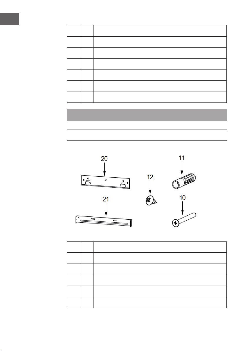
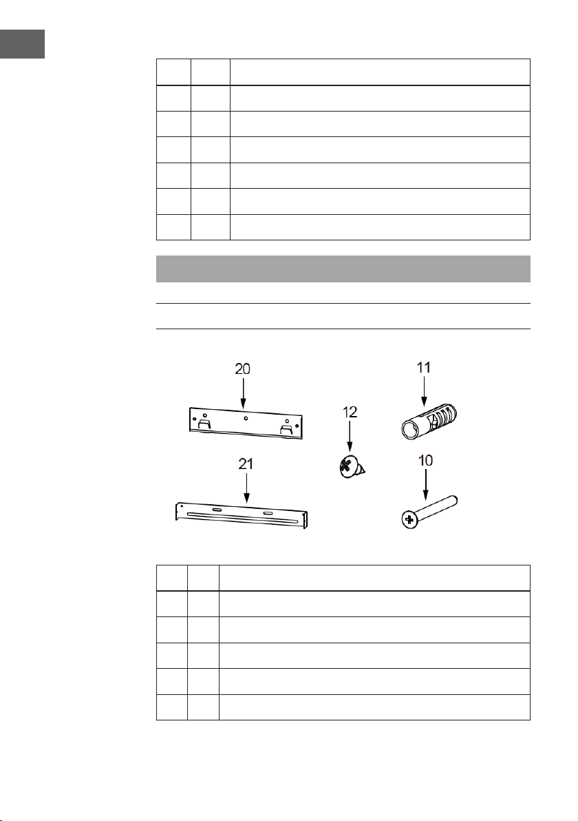
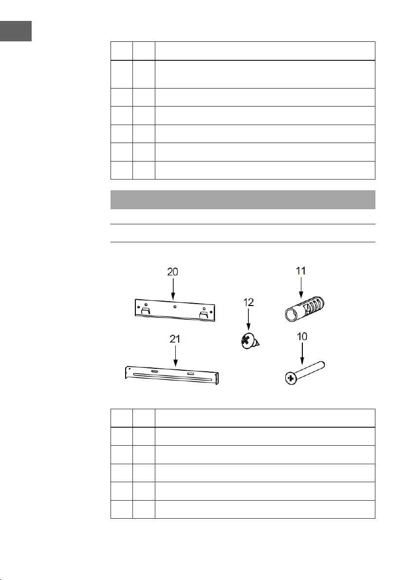
INSTALLATIONSZUBEHÖR
Nr. Stk. Installationskomponenten
10 7 Schrauben 5 x 50
11 7 Wanddübel
12 6 Schrauben 4,2 x 9,5
20 1 Befestigungswinkel Dunstabzugshaube – optional
21 2 Befestigungswinkel Kaminverblendung – optional (0/1)

9
DE
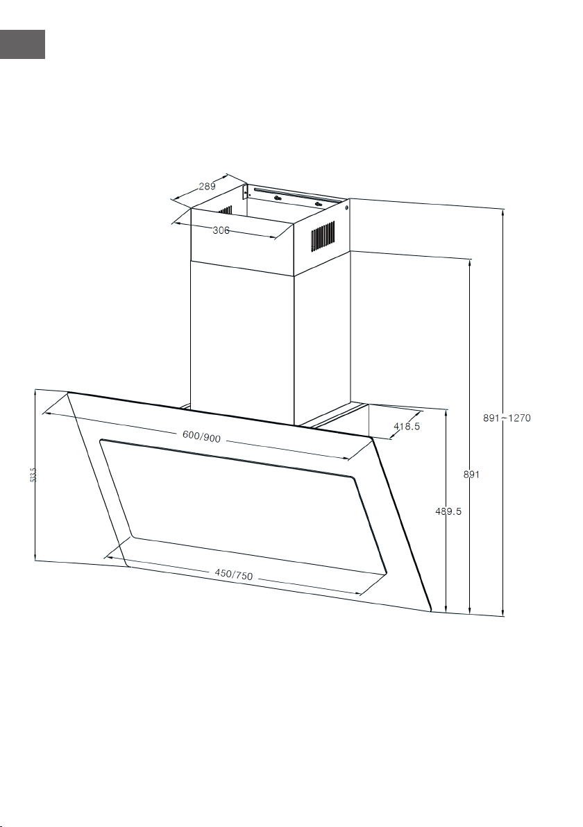
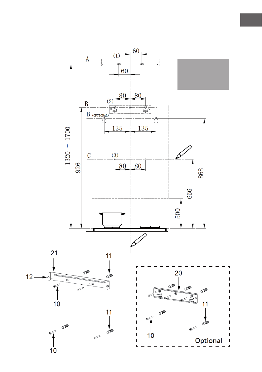
ABMESSUNGEN UND ABSTÄNDE
10
DE
11
DE
INSTALLATION
Hinweis:
Bei den angegebenen
Werten handelt es sich
um [mm].

12
DE
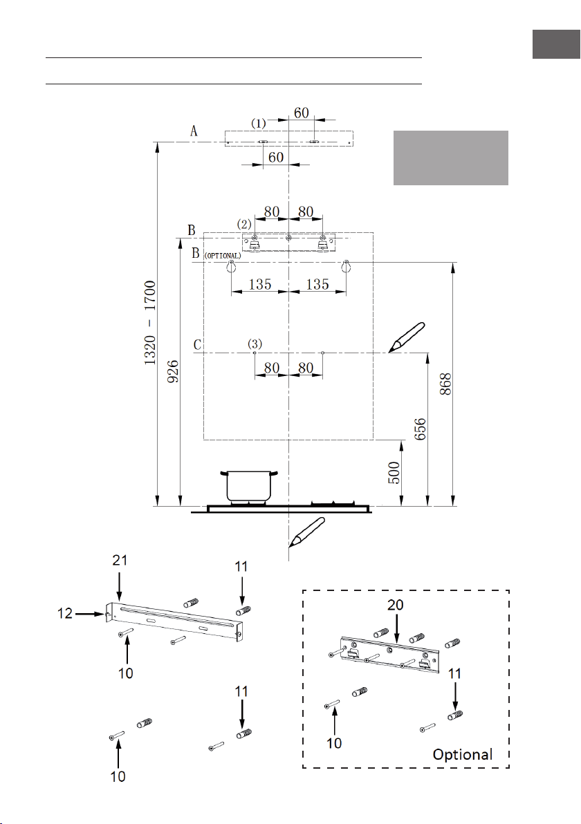
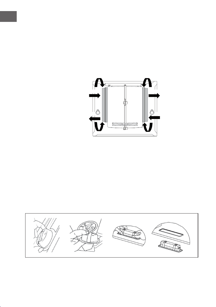
Schritt 1: Gerät richtig platzieren
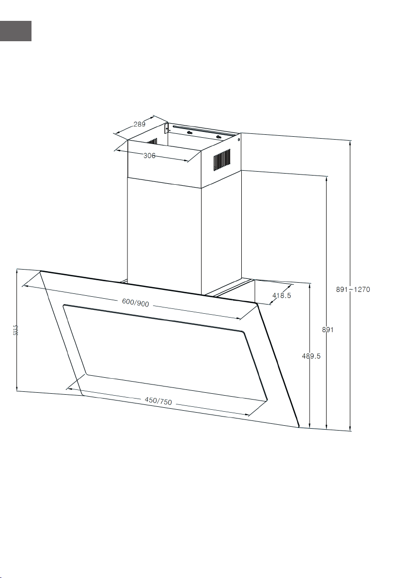
Ziehen Sie im geplanten Installationsbereich folgende Referenzlinien:
• Eine vertikale Linie bis zur Decke oder bis zur oberen Begrenzung des
Installationsbereichs, und zwar in der Mitte der Fläche, an der die
Dunstabzugshaube montiert werden soll.
(A) Eine horizontale Linie A, 1320-1700 mm oberhalb der Kochäche.
(B) Eine horizontale Linie B, mindestens 926 mm (optional 868 mm) oberhalb der
Kochäche.
(C) Eine horizontale Linie C, mindestens 656 mm oberhalb der Kochäche.
Schritt 2: Bohrlöcher markieren
• Markieren Sie einen Punkt (1) auf der horizontalen Linie A, 60 mm rechts von der
vertikalen Bezugslinie.
• Wiederholen Sie diesen Vorgang auf der anderen Seite und überprüfen Sie, ob
sich die beiden Markierungen auf gleicher Höhe benden.
• Markieren Sie einen Punkt (2) auf der horizontalen Linie B, 80 mm (optional
135mm) rechts von der vertikalen Bezugslinie.
• Wiederholen Sie diesen Vorgang auf der anderen Seite und auf der vertikalen
Referenzlinie und überprüfen Sie, ob sich die drei Markierungen auf gleicher Höhe
benden.
• Markieren Sie einen Punkt (3) auf der horizontalen Linie C, 80 mm rechts von der
vertikalen Bezugslinie.
• Wiederholen Sie diesen Vorgang auf der anderen Seite und überprüfen Sie, ob
sich die beiden Markierungen auf gleicher Höhe benden.
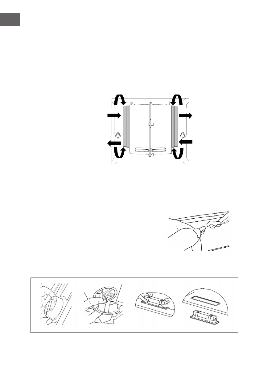
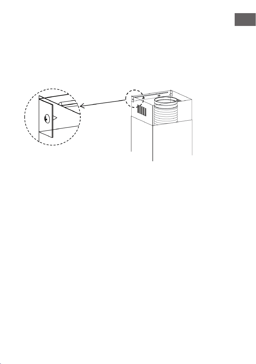
Schritt 3: Halterungen anbringen (optional)
• Bohren Sie an den markierten Stellen (1) (2) (3) mit einem Φ10 mm Bohrer Löcher
für die Schrauben.
• Die Dübel (11) in die Löcher (1) (2) (3) einsetzen.
• Fixieren Sie die Befestigungshalterung für die Dunstabzugshaube (20) mit
3(5x50)-Schrauben (10), die im Lieferumfang enthalten sind.
• Fixieren Sie die Befestigungshalterung für die Kaminverblendung (21) mit
2(5x50)-Schrauben (10), die im Lieferumfang enthalten sind.
13
DE
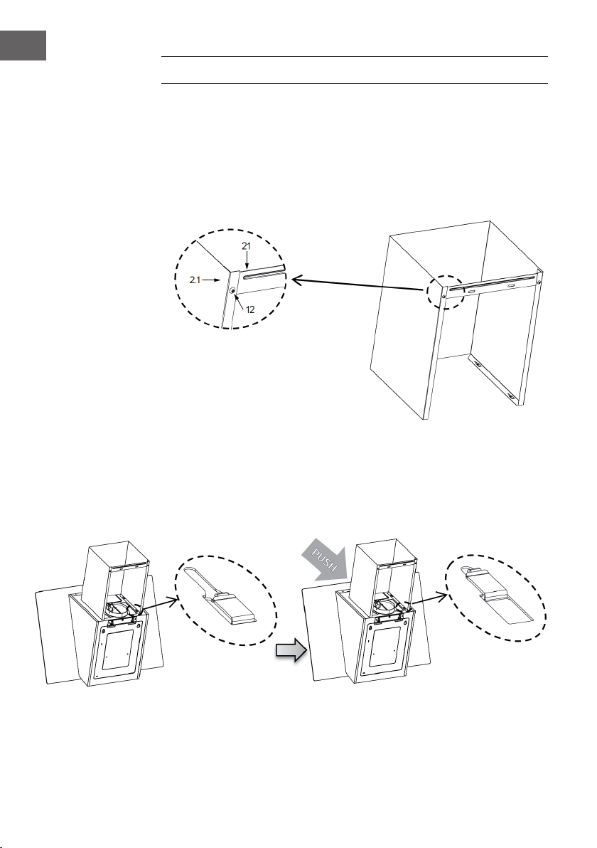
Schritt 4: Gerätekorpus einhängen
• Öffnen Sie die Frontblende (Bedienfeld).
• Entfernen Sie den Metall-Fettlter mithilfe der mitgelieferten Griffe.
• Der Gerätekorpus kann an zwei verschiedenen Stellen eingehängt werden:
1 Entweder Sie hängen den Gerätekorpus an der Halterung (20) ein.
2 Oder Sie befestigen den Gerätekorpus an den (5x50)-Schrauben (10) an
der Punktmarkierung (2).
• Richten Sie den Gerätekorpus so aus, dass er gerade hängt.
Richtig Falsch
• Schrauben Sie von der Innenseite des Gerätegehäuses aus die Schrauben (10) in
die Dübel (11) an den Punkten (3).
• Setzen Sie den Filter in die Abzugshaube ein.
• Schließen Sie das Frontpanel (Bedienfeld).
Installation mit Abluftsystem
Schritt 5: Abzugshaube mit dem Abluftsystem verbinden
• Verbinden Sie die Dunstabzugshaube bei der Installation mit dem Dunstabzug.
Verwenden Sie hierfür entweder ein exibles oder ein starres Rohr mit einem
Durchmesser von 150 mm oder 120 mm. Welches Rohr Sie wählen, bleibt Ihnen
überlassen.
• Wenn Sie eine 120 mm-Abluftverbindung wählen, bringen Sie zusätzlich den
Flansch (3) an der Öffnung des Gerätekorpus an.
• Fixieren Sie das Abluftrohr (4) an der richtigen Stelle und xieren Sie dieses mit
einer ausreichenden Anzahl an Rohrklemmen (nicht im Lieferumfang enthalten).
• Entnehmen Sie gegebenenfalls darin bendliche Kohlelter.

14
DE
INSTALLATION DES DUNSTABZUGS
Der Dunstabzug kann nur in Kombination mit einer Dunstabzugshaube angebracht
werden.
Untere Kaminverblendung
• Montieren Sie eine Befestigungshalterung (21) an die untere Kaminverblendung mit
2(4,2x9,5)-Schrauben (12), die mitgeliefert wurden.
• Drücken Sie die beiden Seiten der unteren Kaminverblendung leicht auseinander
und haken Sie diese am Gerätekorpus der Dunstabzugshaube ein. Achten Sie
darauf, dass die Kaminverblendung gut xiert ist.

15
DE
Obere Kaminverblendung
• Drücken Sie die beiden Seiten der oberen Kaminverblendung leicht auseinander
und hängen Sie diese zwischen der Wand und der Halterung (21) ein, die an der
unteren Kaminverblendung befestigt wurde.
• Befestigen Sie die obere Kaminverblendung mit 2 (4,2x9,5)-Schrauben (12), die
im Lieferumfang enthalten sind, an der Halterung (21).
16
DE
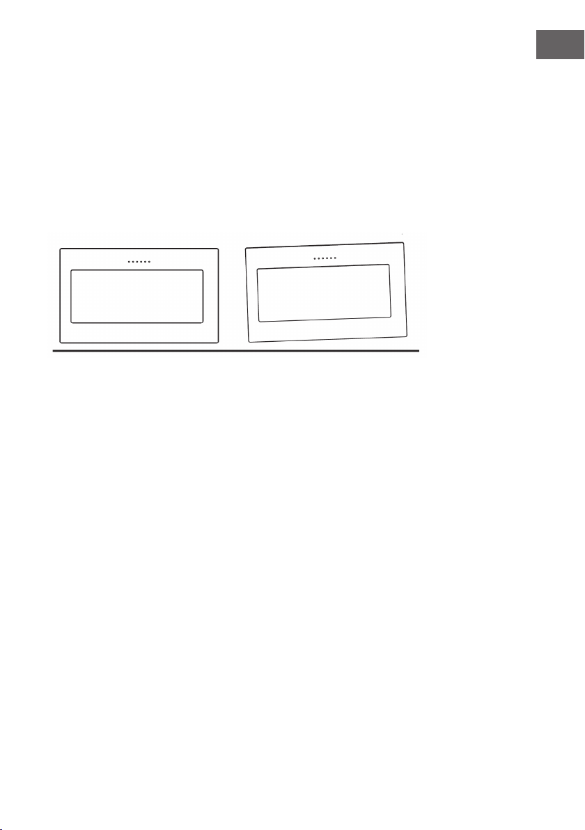
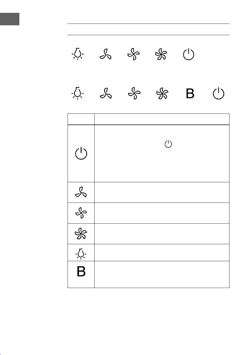
BEDIENFELD
Optional:
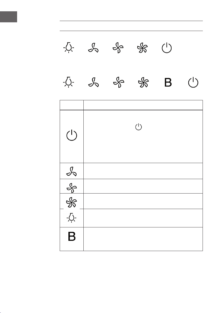
Taste Funktion
Ein: Drücken Sie zum Ein- und Ausschalten diese Taste.
Verzögertes Ausschalten: Taste blinkt
• Wenn Sie zum Ausschalten die Taste einmal drücken, blinkt
die Taste und das Gerät wird erst mit 3Minuten Verzögerung
ausgeschaltet.
• Drücken Sie erneut die Taste und das Gerät schaltet sich sofort
aus.
Geschwindigkeitsregler: Wenn Sie diese Taste drücken, läuft das
Gerät mit langsamer Geschwindigkeit.
Geschwindigkeitsregler: Wenn Sie diese Taste drücken, läuft das
Gerät mit mittlerer Geschwindigkeit.
Geschwindigkeitsregler: Wenn Sie diese Taste drücken, läuft das
Gerät mit hoher Geschwindigkeit.
Licht an/aus: Drücken Sie diese Taste, um das Licht ein- und
auszuschalten.
Geschwindigkeitsschub: Drücken Sie diese Taste, um das Gerät mit
erhöhter Geschwindigkeit laufen zu lassen.
(Optional)

17
DE
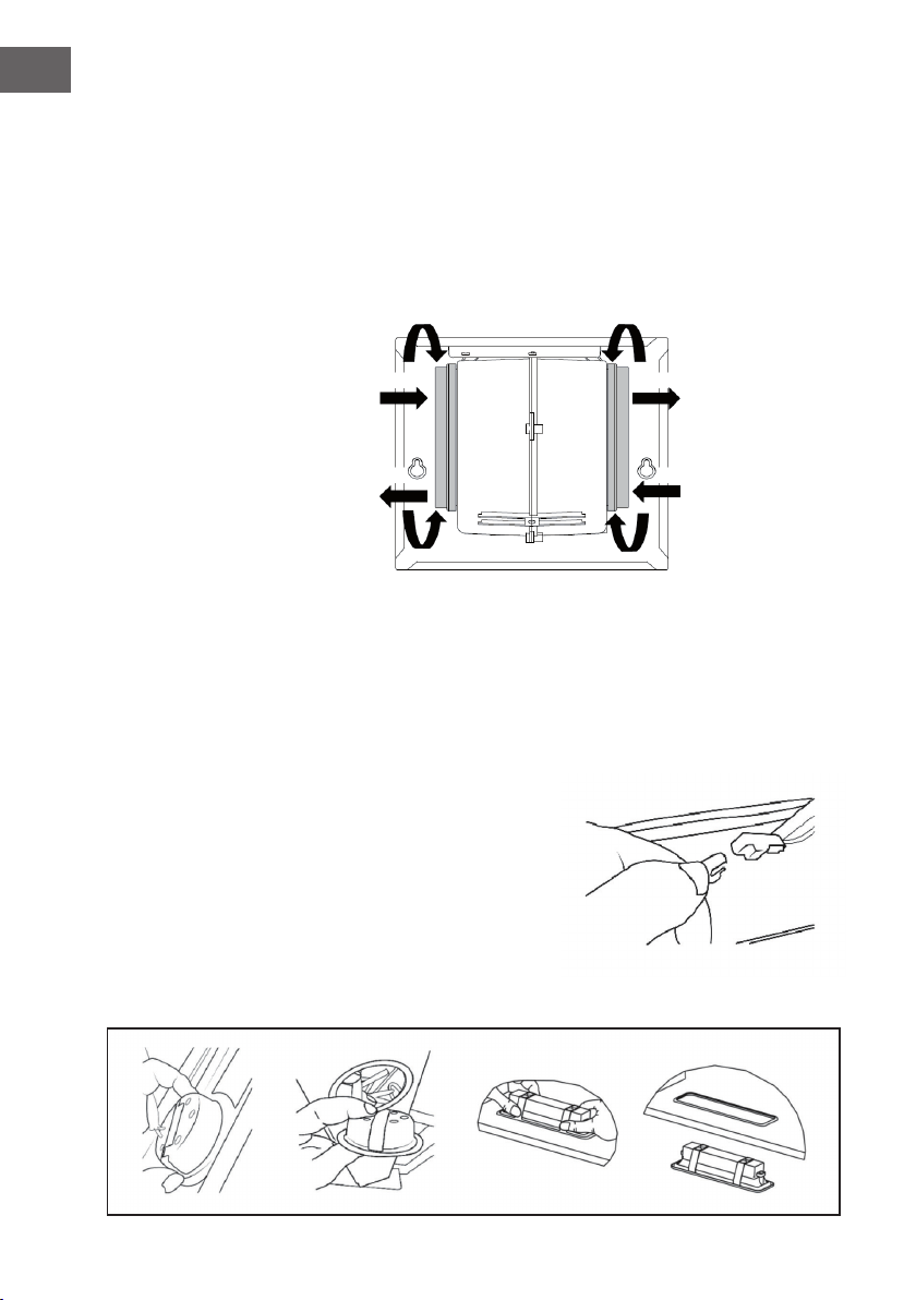
REINIGUNG UND WARTUNG
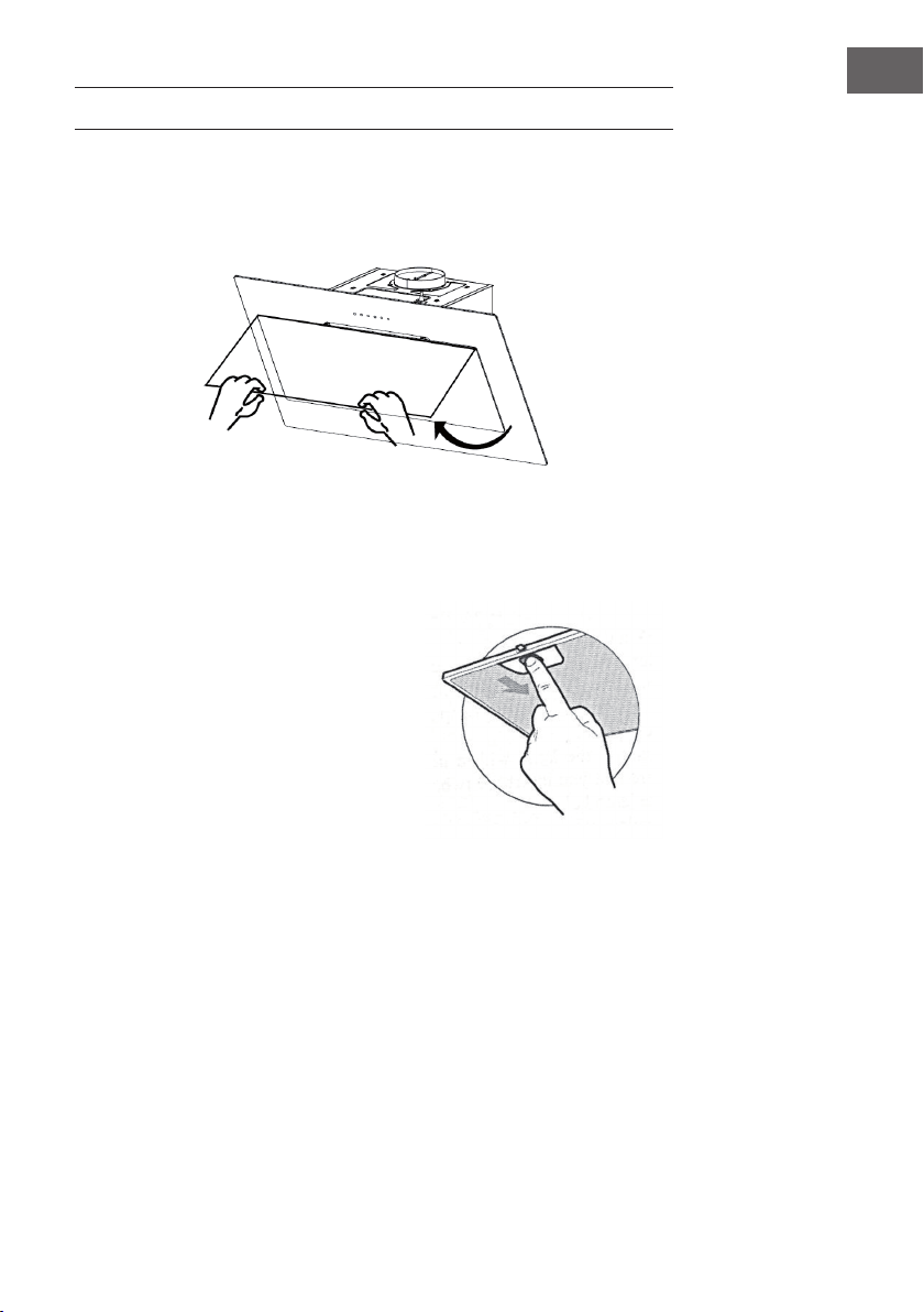
Frontblende öffnen und reinigen
• Drücken Sie zunächst auf die Frontblende und ziehen Sie diese zum Öffnen nach
vorne.
• Reinigen Sie die Außen- und Innenseite mit einem feuchten Tuch und neutralem
Reinigungsmittel. Verwenden Sie niemals nasse Tücher, Schwämme, ießendes
Wasser, Druckreiniger oder Scheuermittel.
Fettlter reinigen
• Die Fettlter müssen, abhängig von der
Verwendungshäugkeit, mindestens alle
2Monate oder häuger gereinigt werden.
Die Filter sind spülmaschinengeeignet.
• Ziehen Sie zum Öffnen an der Verblendung.
• Entnehmen Sie die Filter, indem Sie diese
gegen die Rückseite der Dunstabzugshaube
drücken und gleichzeitig nach unten ziehen.
• Achten Sie darauf, dass sich die Filter während der Reinigung nicht verbiegen.
Bevor Sie die Filter wieder einsetzen, vergewissern Sie sich, dass diese vollständig
getrocknet sind. (Die Farbe der Filteroberäche kann sich im Laufe der Zeit
verändern. Dies hat allerdings keinen Einuss auf die Efzienz des Filters.)
• Achten Sie darauf, dass Sie die Filter nach der Reinigung wieder korrekt, mit dem
Griff nach außen, einsetzen.
Aktivkohlelter (Umluftversion)
• Diese Filter können nicht abgewaschen und wiederverwendet werden.
Aktivkohlelter müssen, je nach Verwendungshäugkeit, mindestens alle 4 Monate
oder häuger gewechselt werden.
18
DE
Aktivkohellter austauschen
1 Öffnen Sie die Blende und ziehen Sie diese nach unten.
2 Entnehmen Sie die metallenen Fettlter.
3 Entnehmen Sie den verschmutzten Aktivkohlelter.
4 Setzen Sie einen neuen Aktivkohlelter Filter ein
5 Setzen Sie die metallenen Fettlter wieder ein.
6 Schließen Sie die Verblendung.
Befestigen
Entfernen
Entfernen
Befestigen
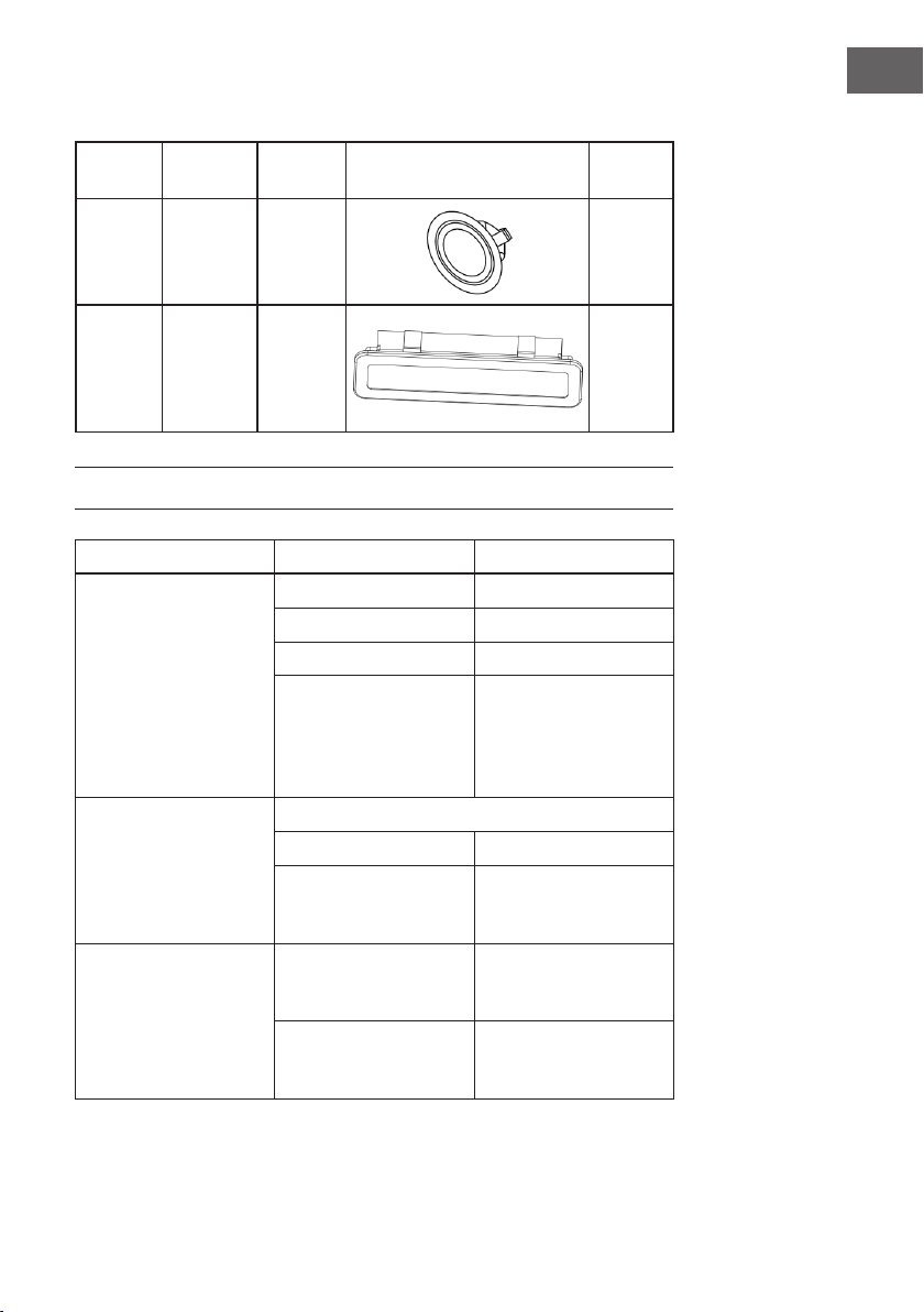
Beleuchtung ersetzen (1,5 W LED Lampe)
• Schalten Sie die Abzugshaube aus und unterbrechen Sie die Stromversorgung des
Geräts (Netzstecker ziehen oder die Sicherung ausschalten).
• Nehmen Sie den Fettlter heraus.
• Nehmen Sie das LED-Lichtmodul heraus, indem Sie die Befestigung des Lichts vom
Gerätegehäuse lösen (gegebenenfalls müssen Sie etwas Druck oder Kraft
anwenden).
• Trennen Sie die Verbindung zwischen der
Klemme und dem LED-Licht.
• Ersetzen Sie die Lampe durch eine im
Handel erhältliche LED-Lampe des
gleichen Typs (1,5 W). Achten Sie darauf,
dass Sie das LED-Licht wieder richtig
anschließen.
• Setzen Sie das Lichtmodul wieder in das
Gerätegehäuse ein.

19
DE
Ersatzlicht
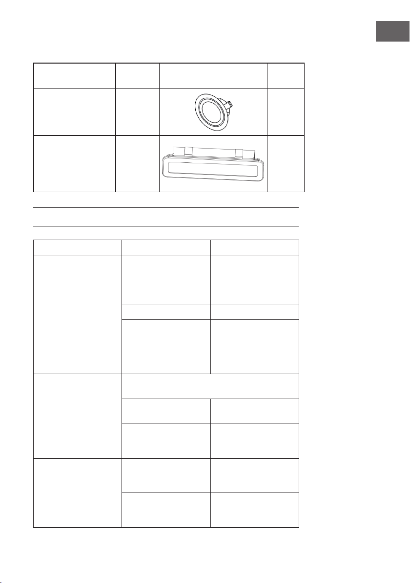
Ø Leistung Spannung Bild
ILCOS D
code
70 mm 1,5 W DC 12 V
DSR-
1.5-S-70
33,2 mm
x 120mm
1.5 W DC 12 V
DSS-1.5-
S-33.2
/ 120
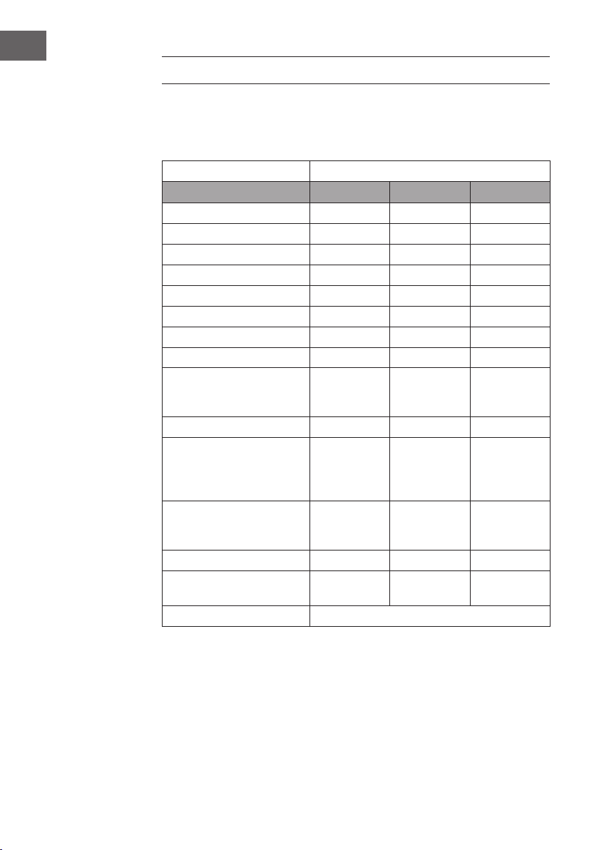
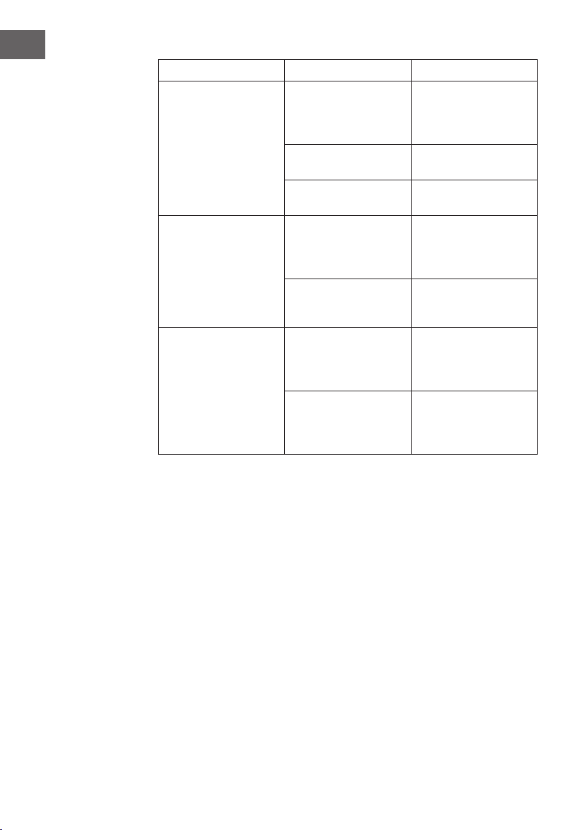
FEHLERSUCHE UND FEHLERBEHEBUNG
Problem Ursache Lösung
Das Licht ist an, aber der
Motor läuft nicht.
Die Flügelblätter sind
blockiert.
Überprüfen Sie die
Flügelblätter.
Der Kondensator ist
beschädigt.
Ersetzen Sie den
Kondensator.
Der Motor ist beschädigt. Ersetzen Sie den Motor.
Die interne Verkabelung
des Motors ist
unterbrochen/defekt.
Es kann zu einem
unangenehmen Geruch
kommen.
Ersetzen Sie den Motor.
Licht und Motor
funktionieren nicht.
Überprüfen Sie, abgesehen von dem oben erwähnten,
Folgendes:
Das Licht ist beschädigt. Ersetzen Sie das Licht.
Das Stromkabel ist lose. Verbinden Sie die
elektrischen Anschlüsse
gemäß dem Schaltbild.
Öl tritt aus Luftein- und -auslass sind
nicht richtig versiegelt.
Nehmen Sie den Auslass
herunter und versiegeln
Sie diesen mit Kleber.
Der Übergang von
U-Prol und Verblendung
ist undicht.
Dichten Sie den Übergang
mit einem geeigneten
Mittel ab.
20
DE
Problem Ursache Lösung
Vibration Die Flügelblätter können,
wenn Sie blockiert sind,
Vibrationen verursachen.
Ersetzen Sie die
Flügelblätter.
Der Motor ist nicht richtig
befestigt.
Befestigen Sie den Motor
richtig.
Die Dunstabzugshaube ist
nicht richtig befestigt.
Befestigen Sie die
Dunstabzugshaube richtig.
Unzureichende
Luftabsaugung
Der Abstand zwischen
Kochäche und
Dunstabzugshaube ist zu
groß.
Passen Sie den Abstand
an.
Zu viel Luftzug durch
geöffnete Türen oder
Fenster.
Wählen Sie einen neuen
Installationsort oder
schließen Sie Türen und
Fenster.
Das Gerät neigt sich nach
vorne.
Die Fixierschrauben
wurden nicht fest genug
angezogen.
Ziehen Sie die Schrauben
fest und richten Sie die
Dunstabzugshaube
horizontal aus.
Die Halterungsschrauben
wurden nicht fest genug
angezogen.
Ziehen Sie die Schrauben
fest und richten Sie die
Dunstabzugshaube
horizontal aus.

21
DE
HINWEISE ZUR ENTSORGUNG
Wenn es in Ihrem Land eine gesetzliche Regelung zur
Entsorgung von elektrischen und elektronischen Geräten
gibt, weist dieses Symbol auf dem Produkt oder auf der
Verpackung darauf hin, dass dieses Produkt nicht im
Hausmüll entsorgt werden darf. Stattdessen muss es zu
einer Sammelstelle für das Recycling von elektrischen
und elektronischen Geräten gebracht werden. Durch
regelkonforme Entsorgung schützen Sie die Umwelt und die
Gesundheit Ihrer Mitmenschen vor negativen Konsequenzen.
Informationen zum Recycling und zur Entsorgung dieses
Produkts, erhalten Sie von Ihrer örtlichen Verwaltung oder
Ihrem Hausmüllentsorgungsdienst.
HERSTELLER & IMPORTEUR (UK)
Hersteller:
Chal-Tec GmbH, Wallstraße 16, 10179 Berlin, Deutschland.
Importeur für Großbritannien:
Chal-Tec UK limited
Unit 6 Riverside Business Centre
Brighton Road
Shoreham-by-Sea
BN43 6RE
United Kingdom
22
DE
PRODUKTDATENBLATT
Angaben nach Verordnung (EU) Nr. 65/2014
Mess- und Berechnungsmethoden nach EN 61591:1997+A1:2006+A2:2011+A11:201
4+A12:2015
Artikelnummer
10033707, 10033708
Bezeichnung Symbol Wert Einheit
Jährlicher Energieverbrauch AEC
hood
91,8 kWh/Jahr
Energieefzienzklasse C
uiddynamische Efzienz FDE
hood
18,1
Klasse für die uiddynamische
Efzienz
D
Beleuchtungsefzienz LE
hood
41 Lux/W
Beleuchtungsefzienzklasse A
Fettabscheidegrad GFE
hood
77,3 %
Klasse für den Fettabscheidegrad C
Luftstrom bei minimaler und bei
maximaler Geschwindigkeit im
Normalbetrieb, ausgenommen den
Betrieb auf der Intensivstufe oder
Schnelllaufstufe
285,7 / 624,7 m³/h
Luftstrom im Betrieb auf der
Intensivstufe oder Schnelllaufstufe
- m³/h
A-bewertete Luftschallemissionen
bei minimaler und maximaler
verfügbarer Geschwindigkeit im
Normalbetrieb
49 / 66 dB
A-bewertete Luftschallemissionen
im Betrieb auf der Intensivstufe
oder Schnelllaufstufe
- dB
Leistungsaufnahme im Aus-Zustand P
o
0.0 W
Leistungsaufnahme im
Bereitschaftszustand
P
s
0.44 W
Kontaktangaben Chal-Tec GmbH, Wallstraße 16, 10179, Berlin,
Deutschland

23
DE
Angaben nach Verordnung (EU) Nr. 66/2014
Mess- und Berechnungsmethoden nach EN 61591:1997+A1:2006+A2:2011+A11:201
4+A12:2015
Artikelnummer
10033707, 10033708
Bezeichnung Symbol Wert Einheit
Jährlicher Energieverbrauch AEC
hood
91,8 kWh/Jahr
Zeitverlängerungsfaktor f 1,3
Fluiddynamische Efzienz FDE
hood
18,1
Energieefzienzindex EEI
hood
76,0
Gemessener Luftvolumenstrom im
Bestpunkt
Q
BEP
362,0 m³/h
Gemessener Luftdruck im Bestpunkt P
BEP
340 Pa
Maximaler Luftstrom Q
max
624,7 m³/h
Gemessene elektrische
Eingangsleistung im Bestpunkt
W
BEP
188,8 W
Nennleistung des
Beleuchtungssystems
W
L
3 W
Durchschnittliche
Beleuchtungsstärke des
Beleuchtungssystems auf der
Kochoberäche
E
middle
124 Lux
Gemessene Leistungsaufnahme im
Bereitschaftszustand
P
o
0.0 W
Gemessene Leistungsaufnahme im
Aus-Zustand
P
s
0.44 W
Schallleistungspegel L
WA
66 dB
Kontaktangaben Chal-Tec GmbH, Wallstraße 16, 10179, Berlin,
Deutschland


25
EN
Dear Customer,
Congratulations on purchasing this device. Please read the
following instructions carefully and follow them to prevent
possible damages. We assume no liability for damage caused
by disregard of the instructions and improper use. Scan the QR
code to get access to the latest user manual and more product
information.
CONTENT
Produktdatenblatt22
Safety Instructions26
Notes on Environmental Protection28
Device Overview29
Dimensions31
Installation33
Control Panel38
Cleaning and Maintenance39
Troubleshooting41
Disposal Considerations43
Manufacturer & Importer (UK)43
Product Data Sheet44
TECHNICAL DATA
Item number 10033707, 10033708
Power supply 220-240 V ~ 50/60 Hz
Note: You can purchase an activated carbon lter separately for this cooker hood
under item number 10033740. Please visit our website: www.hi-tower.co.uk

26
EN
SAFETY INSTRUCTIONS
• Thank you for purchasing this cooker hood. Please read the instruction manual
carefully before you use the cooker hood, and keep it in a safe place.
• The installation work must be carried out by a qualied electrician or competent
person. Before you use the cooker hood, make sure that the voltage (V) and the
frequency (Hz) indicated on the cooker hood are exactly the same as the voltage
and the frequency in your home.
• The manufacturer and the agent will not bear any responsibility for the damage
caused by inappropriate installation and usage.
• Children under the age of 8 must not use the cooker hood.
• The appliance is not intended for commercial use, but only for household and
similar environments.
• The cooker hood and its lter mesh should be cleaned regularly in order to keep it
in good working order.
• Before cleaning, switch the power off at the main supply.
• Clean the cooker hood according to the instruction manual and keep the cooker
hood from the danger of burning.
• Prohibit putting the cooker hood by re.
• If the appliance does not function normally, contact the manufacturer or a specialist
company.
• This device may be only used by children 8 years old or older and persons with
limited physical, sensory and mental capabilities and / or lack of experience
and knowledge, provided that they have been instructed in use of the device by a
responsible person who understands the associated risks.
• If the supply cord is damaged, it must be replaced by the manufacturer, its service
agent or similarly qualied persons in order to avoid a hazard.
• If the range hood is used at the same time as appliances burning gas or other fuels,
the room must be adequately ventilated.
• Do not ambé under the range hood. Accessible parts may become hot when used
with cooking appliances.
Important hints on installation
• The air must not be discharged into a ue that is used for exhausting fumes from
appliances burning gas or other fuels (not applicable to appliances that only
discharge the air back into the room).
• Regulations concerning the discharge of air have to be fullled.
27
EN
Important notes about the extraction mode
WARNING
Risk of poisoning from exhaust gases sucked back. Never operate
the device in extraction mode simultaneously with an open flue
appliance when there is not adequate airflow guaranteed.
Open ue combustion equipment (for example, gas, oil, wood or coal- red heaters,
tankless water heaters, water heaters) pulls combustion air from the room and runs
it through an exhaust pipe or chimney to the outside. In the extraction mode, indoor
air is removed from the kitchen and the adjacent rooms - without suf cient air intake
this creates a vacuum. Toxic gases from the chimney or extraction ue can thereby be
sucked back into the living spaces.
• Always ensure that a suf cient supply of fresh air is guaranteed and that the air can
circulate.
• An air supply / extractor box alone does not ensure compliance with the limit
value.
Safe operation is only possible when the negative pressure in the room where the
appliance is located does not exceed 4 Pa (0.04 mbar). This can be achieved when
the air required for combustion can ow through openings that are not closable, for
example in doors, windows, in conjunction with an air supply / extractor box or
through other technical measures. In any case, consult a quali ed chimney sweep who
can assess the entire ventilation of your house and propose appropriate measures for
adequate ventilation.
If the hood is used exclusively in the recirculation mode, unrestricted operation is
possible.
Important note on disassembly of the device
• Disassembly is similar to installation/assembly in reverse order.
• Take a second person to help you during disassembly to avoid injuries.

28
EN
NOTES ON ENVIRONMENTAL PROTECTION
• During cooking, make sure that there is sufcient air supply so that the cooker hood
can operate efciently and with low operating noise.
• Adjust the fan speed to the amount of steam produced during cooking. Use the
intensive mode only when necessary. The lower the fan speed, the less energy is
consumed.
• If large amounts of steam are produced during cooking, select a higher fan speed
in good time. If the cooking steam has already dispersed in the kitchen, the cooker
hood must be operated longer.
• Switch off the cooker hood when you no longer need it.
• Switch off the lighting when you no longer need it.
• Clean the lter at regular intervals and replace it if necessary to increase the
effectiveness of the ventilation system and prevent re hazards.
• Always put the lid on when cooking to reduce cooking steam and condensation.
29
EN
DEVICE OVERVIEW
30
EN
Ref.. Qty. Product Components
1 1 Hood Body, complete with: Controls, Light, Blower, Filter.
2.1 1 Lower Decorative Chimney – optional
2.2 1 Upper Decorative Chimney – optional
3 1 Flange – optional
4 1 Exhaust Pipe
5 2 Activated Charcoal Filter – optional
Note: The optional accessory is not included in the delivery.
INSTALLATION COMPONENTS
Ref. Qty. Installation components
10 7 Screws 5 x 50
11 7 Wall Plugs
12 6 Screws 4,2 x 9,5
20 1 Hood xing bracket – optional
21 2 Chimney xing bracket – optional (0/1)

31
EN
DIMENSIONS
32
EN

33
EN
INSTALLATION
Note:
The specied values
are [mm].

34
EN
Step 1: Correct placement of the cooker hood
In the planned installation area, draw the following reference lines:
• A vertical line to the ceiling or to the top of the installation area, in the middle of the
area where the cooker hood is to be mounted.
(A) A horizontal line A, at 980-1080 mm above the cooker top.
(B) A horizontal line B, at a minimum 926 mm (868 mm optional) above the cooker
top.
(C) A horizontal line C, at a minimum 656 mm above the cooker top.
Step 2: Mark drill holes
• Mark a point (1) on the horizontal line A, 60 mm to the right of the vertical
reference line.
• Repeat this operation on the other side, checking that the two marks are levelled.
• Mark a point (2) on the horizontal line B, 80 mm (135 mm optional) to the right of
the vertical reference line.
• Repeat this operation on the other side and on the vertical reference line, checking
that the three marks are levelled.
• Mark a point (3) on the horizontal line C, 80 mm to the right of the vertical
reference line.
• Repeat this operation on the other side, checking that the two marks are levelled.
Step 3: Fix the brackets (optional)
• Drill at the marked points (1) (2) (3), using a Φ10 mm drill bit.
• Insert the wall plugs (11) into the holes (1) (2) (3).
• Fix the hood xing bracket (20) with 3 (5 x 50) screws (10) supplied with the hood.
• Fix a chimney xing bracket (21) with 2 (5 x 50) screws (10) supplied with the
hood.

35
EN
Step 4: Hook the hood body:
• Open the panel.
• Remove the metal grease lter using the handles provided.
• The hood body can be hooked into two different places:
1 Either hook the hood body to the bracket (20).
2 Or hook the hood body to the (5 x 50) screws (10) at the points (2).
• Level the hood body itself.
Right Wrong
• From the inside of the hood body, x the screws (10) to the wall plugs (11) at the
points (3).
• Fit the lter into the hood.
• Close the panel.
Installation with air exhaust system (ducted version)
Step 5: Connect the hood to the air exhaust system
• When installing the ducted version, connect the hood to the chimney using either a
exible or rigid pipe 150 mm or 120 mm, the choice of which is left to the installer.
• To install a 120 mm air exhaust connection, insert the reducer ange (3) on the
hood body outlet.
• Fix the pipe (4) in position using sufcient pipe clamps (not supplied).
• Remove possible charcoal lters.

36
EN
CHIMNEY ASSEMBLY
The chimney can only be installed with exhausting hood.
Lower decorative chimney
• Fix a chimney xing bracket (21) onto the lower decorative chimney with
2(4.2x9.5) screws (12) supplied with the hood.
• Slightly widen the two sides of the ue and hook them onto the hood body, making
sure that they are well seated.

37
EN
Upper decorative chimney
• Slightly widen the two sides of the upper chimney and hook them between the wall
and the bracket (21), which is xed on the lower decorative chimney.
• Fix the upper chimney onto the bracket (21) with 2 (4.2 x 9.5) screws (12) supplied
with the hood.
38
EN
CONTROL PANEL
Optional:
Button Function
ON: Press this button to start the motor operation.
Delayed switch-off: Button ashes
• If you press the button once to switch the motor operation off, the
button ashes and the motor is only switched off after a delay of
3 minutes.
• Press the button again and the motor switches off immediately.
Speed switch: Press this button and the motor runs at low speed.
Speed switch: Press this button and the motor runs at medium speed.
Speed switch: Press this button and the motor runs at high speed.
On/Off lighting: Press this button to turn on the lights, and press
again to turn them off.
Speed BOOST: Press this button, to turn the motor on at speed boost.
(Optional)
39
EN
CLEANING AND MAINTENANCE
Opening and cleaning the panel
• Push the panel rst and then pull it to open.
• Clean the outside and inside with a damp cloth and a neutral detergent. Do not use
wet clothes, sponges, running water, pressure washers or abrasive cleaners.
Cleaning the grease lters
• The lters must be cleaned every 2months of
operation, or more frequently for particularly
heavy usage, and can be washed in a
dishwasher.
• Pull the comfort panels to open them.
• Remove the lters one by one pushing them
towards the back side of the hood unit and
simultaneously pulling downwards.
• Any kind of bending of the lters has to be
avoided when washing them. Before tting
them again into the hood make sure that they are completely dry. (The color of the
lter surface may change throughout the time but this has no inuence to the lter
efciency).
• When tting the lters into the hood pay attention that they are mounted in correct
position the handle facing outwards.
• Close the comfort panel.
Activated charcoal lters (recirculation version)
• These lters are not washable and cannot be regenerated, and must be replaced
approximately every 4 months of operation, or more frequently with heavy usage.
40
EN
Replacing the activated charcoal lters:
1 Open the comfort panels pulling them downwards.
2 Remove the metal grease lters
3 Remove the saturated activated charcoal lter.
4 Fit the new lters.
5 Replace the metal grease lters.
6 Close the comfort panel.
Fix
Remove
Remove
Fix
Light Replacement (1.5 W LED light)
• Switch off the extractor hood and isolate the extractor hood by pulling out the mains
plug or switching off the fuse.
• Remove the grease lter.
• Remove the light by levering its tting from
the hood body (this may require pressure
or force to be applied).
• Disconnect the connector of the light
• Replace the light with a new one of the
same type (1.5 W LED light),making sure
that you connect the light with the light
cable correctly.
• Reinstall the light back to the hood body.
41
EN
Replacement light
Ø
Max.
Power
Voltage Picture
ILCOS D
code
70 mm 1.5 W DC 12 V
DSR-
1.5-S-70
33,2 mm
x 120mm
1.5 W DC 12 V
DSS-1.5-
S-33.2
/ 120
TROUBLESHOOTING
Problem Cause Solution
Light on, but motor does
not work.
The blades are blocked. Check the blades.
The capacitor is damaged. Replace the capacitor.
The motor is damaged. Replace the motor.
The internal wiring of
the motor is cut off/
disconnected.
An unpleasant smell may
be produced.
Replace the motor.
Both light and motor do
not work.
Apart from the above mentioned, check the following:
The light is damaged. Replace the lights.
The power cord is loose. Connect the wires as
shown in the electric
diagram.
Oil leakage Outlet and the air
ventilation entrance are
not tightly sealed.
Take down the outlet and
seal with glue.
The connection of the
U-shaped section and the
cover is leaking.
Take the U-shaped section
down and seal it with a
suitable material.
42
EN
Problem Cause Solution
Vibration The blade, if damaged,
can cause vibrating.
Replace the blade.
The motor is not tightly
fastened.
Fasten the motor tightly.
The cooker hood is not
tightly xed.
Fix the cooker hood
tightly.
Insufcient suction The distance between
the cooker hood and the
cooker top is too large.
Readjust the distance.
Too much ventilation from
open doors or windows.
Choose a new place
to install the appliance
or close the doors and
windows.
The machine inclines The xing screws are not
tight enough.
Tighten the xing screws
and align the hood
horizontally.
The hanging screws are
not tight enough.
Tighten the hanging
screw and align the hood
horizontally.
43
EN
DISPOSAL CONSIDERATIONS
If there is a legal regulation for the disposal of electrical
and electronic devices in your country, this symbol on the
product or on the packaging indicates that this product must
not be disposed of with household waste. Instead, it must be
taken to a collection point for the recycling of electrical and
electronic equipment. By disposing of it in accordance with
the rules, you are protecting the environment and the health of
your fellow human beings from negative consequences. For
information about the recycling and disposal of this product,
please contact your local authority or your household waste
disposal service.
MANUFACTURER & IMPORTER (UK)
Manufacturer:
Chal-Tec GmbH, Wallstrasse 16, 10179 Berlin, Germany.
Importer for Great Britain:
Chal-Tec UK limited
Unit 6 Riverside Business Centre
Brighton Road
Shoreham-by-Sea
BN43 6RE
United Kingdom
44
EN
PRODUCT DATA SHEET
Information according to Regulation (EU) No. 65/2014
Measurement and calculation methods according to EN 61591:1997+A1:2006+A2:20
11+A11:2014+A12:2015
Item number
10033707, 10033708
Description Symbol Value Unit
Annual Energy Consumption AEC
hood
91,8 kWh/Year
Energy Efciency class C
Fluid Dynamic Efciency FDE
hood
18,1
Fluid Dynamic Efciency class D
Lighting Efciency LE
hood
41 Lux/W
Lighting Efciency class A
Grease Filtering Efciency GFE
hood
77,3 %
Grease Filtering Efciency class C
air ow at minimum and maximum
speed in normal use, intensive or
boost excluded
285,7 / 624,7 m³/h
air ow at intensive or boost setting - m³/h
airborne acoustical A-weighted
sound power emissions at minimum
and maximum speed available in
normal use
49 / 66 dB
airborne acoustical A-weighted
sound power emissions at intensive
or boost setting
- dB
power consumption in off mode P
o
0.0 W
power consumption in standby
mode
P
s
0.44 W
Contact details Chal-Tec GmbH, Wallstraße 16, 10179, Berlin, Germany

45
EN
Information according to Regulation (EU) No. 66/2014
Measurement and calculation methods according to EN 61591:1997+A1:2006+A2:20
11+A11:2014+A12:2015
Item number
10033707, 10033708
Description Symbol Value Unit
Annual Energy Consumption AEC
hood
91,8 kWh/Year
Time increase factor f 1,3
Fluid Dynamic Efciency FDE
hood
18,1
Energy Efciency Index EEI
hood
76,0
Measured air ow rate at best
efciency point
Q
BEP
362,0 m³/h
Measured air pressure at best
efciency point
P
BEP
340 Pa
Maximum air ow Q
max
624,7 m³/h
Measured electric power input at
best efciency point
W
BEP
188,8 W
Nominal power of the lighting
system
W
L
3 W
Average illumination of the lighting
system on the cooking surface
E
middle
124 Lux
Measured power consumption in
standby mode
P
o
0.0 W
Measured power consumption
off mode
P
s
0.44 W
Sound power level L
WA
66 dB
Contact details Chal-Tec GmbH, Wallstraße 16, 10179, Berlin, Germany


47
ES
Estimado cliente,
Le felicitamos por la adquisición de este producto. Lea
atentamente las siguientes instrucciones y sígalas para evitar
posibles daños. No asumimos ninguna responsabilidad por los
daños causados por el incumplimiento de las instrucciones y el
uso inadecuado. Escanee el siguiente código QR para obtener
acceso a la última guía del usuario y más información sobre
el producto.
ÍNDICE
Product Data Sheet44
Indicaciones de seguridad48
Notas para cuidar del medio ambiente50
Visión general del aparato 51
Dimensiones y distancias53
Instalación55
Panel de control60
Limpieza y mantenimiento61
Detección y resolución de problemas63
Retirada del aparato65
Fabricante e importador (Reino Unido)65
Ficha técnica del producto66
DATOS TÉCNICOS
Número de artículo 10033707, 10033708
Fuente de alimentación 220-240 V ~ 50/60 Hz
Nota: Para esta campana extractora puede adquirir un ltro de carbón activo con el
número de artículo 10033740 . Para ello, visite nuestra página web:
www.elektronik-star.es

48
ES
INDICACIONES DE SEGURIDAD
• Lea atentamente todas las indicaciones y conserve este manual para consultas
posteriores.
• Los trabajos de montaje deben ser realizados solamente por un electricista u otro
profesional. Antes de utilizar la campana extractora, asegúrese de que la tensión
(V) y la frecuencia indicada en la campana extractora (Hz) coinciden con la
tensión (V) y frecuencia (Hz) de su suministro eléctrico.
• La empresa no se responsabiliza de los daños ocasionados por un uso o
instalación indebida del producto.
• Los niños menores de 8 años no deben utilizar la campana extractora.
• Este aparato no ha sido concebido para un uso comercial, sino doméstico o para
entornos similares.
• Limpie el aparato y el ltro con regularidad para que el aparato funcione siempre
de manera eciente. Desconecte el enchufe antes de limpiar el aparato.
• Limpie el aparato solamente según se describe en estas instrucciones.
• No utilice fuentes de ignición bajo la campana extractora.
• Si el aparato no funciona correctamente, contacte inmediatamente con el
fabricante.
• Este aparato puede ser utilizado por niños mayores de 8 años y personas con
discapacidades físicas, sensoriales y mentales y/o con falta de experiencia y
conocimientos, siempre y cuando hayan sido instruidos sobre el uso del aparato y
comprendan los peligros y riesgos asociados.
• Si el cable de alimentación o el enchufe están dañados, deberán ser sustituidos por
el fabricante, un servicio técnico autorizado o una persona igualmente cualicada.
• Si utiliza la campana extractora con hornillos y entren en combustión el gas u otras
sustancias combustibles, deberá garantizar una buena ventilación de la sala.
• No amee nada bajo la campana extractora.
• Advertencia: La supercie del aparato puede alcanzar temperaturas muy elevadas
durante el funcionamiento.
Indicaciones importantes de instalación
• El aire no puede desviarse a un tiro de salida que se emplee para evacuar humos
de gases u otras sustancias inamables (no se aplica para aparatos que solo
desvíen el aire a la sala).
• Siga todas las disposiciones locales para montar las instalaciones de ventilación.

49
ES
Notas importantes acerca del modo de extracción
ADVERTENCIA
Peligro de muerte, riesgo de intoxicación provocado por gases en
combustión aspirados. Nunca ponga en funcionamiento la función
de extracción simultáneamente con un dispositivo que genere calor
en una estancia estanca si no se ha garantizado una ventilación
su ciente.
Los dispositivos no estancos que generan calor (por ejemplo, radiadores que funcionan
con gas, aceite, madera o carbón, calentadores, calentadores de agua) extraen el aire
de combustión de la estancia correspondiente y canalizan el aire de salida por medio
de un tiro (por ejemplo una chimenea) hacia el exterior. Al encender simultáneamente
una campana extractora, el aire de la cocina y de las estancias colindantes se extrae
y sin su ciente aire adicional se produce el fenómeno de presión hipoatmosférica. Los
gases nocivos de la chimenea o del ori cio de salida retornan a la estancia.
• Siempre debe proveer de su ciente aire adicional a la estancia.
• Un conducto de ventilación y evacuación no garantiza en su totalidad que se
cumpla el valor límite.
Solo se garantizará un funcionamiento sin riesgos cuando presión hipoatmosférica en la
estancia del dispositivo generador de calor no supere los 4 Pa (0,04 mbar). Esto podrá
conseguirse cuando el aire necesario para la combustión pueda circular por ori cios
sin cierre, como puertas o ventanas, junto con un conducto de ventilación o evacuación
o a través de otros medios técnicos. En cualquier caso, siga el consejo del constructor
de chimeneas autorizado que pueda evaluar la conexión de ventilación general de su
hogar y tomar las medidas necesarias.
Si pone en funcionamiento la campana extractora en modo circulación de aire, puede
utilizarla sin ninguna limitación.
Nota importante sobre el desmontaje del aparato
• El desmontaje es igual que el montaje pero en orden inverso.
• Al desmontar el aparato, pida ayuda a una segunda persona para evitar lesiones.

50
ES
NOTAS PARA CUIDAR DEL MEDIO AMBIENTE
• Durante la cocción, asegúrese de que haya un ujo de aire suciente para que la
campana extractora funcione ecazmente y con poco ruido de funcionamiento.
• Ajuste la velocidad del ventilador a la cantidad de vapor producida durante la
cocción. Utilice el modo intensivo sólo cuando sea necesario. Cuanto menor sea la
velocidad del ventilador, menos energía consume.
• Si se producen grandes cantidades de vapor durante la cocción, seleccione una
velocidad de ventilador más alta. Si el vapor de la cocción ya se ha extendido por
toda la cocina, la campana extractora debe funcionar durante más tiempo.
• Apague la campana extractora cuando ya no la necesite.
• Apaga la iluminación cuando ya no la necesites.
• Limpie el ltro a intervalos regulares y sustitúyalo si es necesario, para aumentar la
ecacia del sistema de ventilación y prevenir los riesgos de incendio.
• Ponga siempre la tapa cuando cocine para reducir el vapor de la cocción y la
condensación.

51
ES
VISIÓN GENERAL DEL APARATO

52
ES
Núm. Uds. Componentes del aparato
1 1 Base del aparato, que incluye: Elementos de control, luz, ventilador,
ltro
2.1 1 Revestimiento inferior de la campana - opcional
2.2 1 Revestimiento superior de la campana - opcional
3 1 Brida (conexión del conducto) - opcional
4 1 Conducto de extracción
5 2 Filtro de carbón activo (opcional)
Nota: Los accesorios opcionales no están incluidos en el envío.
ACCESORIOS DE INSTALACIÓN
Núm. Uds. Componentes de instalación
10 7 Tornillos 5 x 50
11 7 Tacos para pared
12 6 Tornillos 4,2 x 9,5
20 1 Soporte de jación de la campana - opcional
21 2 Soporte de jación del revestimiento de la campana - opcional
(0/1)

53
ES
DIMENSIONES Y DISTANCIAS

54
ES
55
ES
INSTALACIÓN
Nota: Las medidas
indicadas se expresan
en „mm“.

56
ES
Paso 1: Colocar correctamente el aparato
Trace las siguientes líneas de referencia en la zona de instalación que ha seleccionado:
• Una línea vertical hasta el techo o hasta el límite superior de la zona de instalación
que se encuentre en el centro de la supercie en la que se instalará la campana
extractora.
(A) Una línea horizontal A, a 1320-1700 mm por encima de la supercie de cocción.
(B) Una línea horizontal B, como mínimo a 926 mm (opcionalmente a 868 mm) por
encima de la supercie de cocción.
(C) Una línea horizontal C, a 656 mm como mínimo por encima de la supercie de
cocción.
Paso 2: Marcar los oricios
• Marque un punto (1) sobre la línea horizontal A, a 60 mm a la derecha de la línea
de referencia vertical.
• Repita este proceso en el otro lado y compruebe que ambas marcas se encuentren
a la misma altura.
• Marque un punto (2) sobre la línea horizontal B, a 80 mm (opcionalmente a
135mm) a la derecha de la línea de referencia vertical.
• Repita este proceso en el otro lado y en la línea de referencia vertical y compruebe
que ambas marcas se encuentren a la misma altura.
• Marque un punto (3) sobre la línea horizontal C, a 80 mm a la derecha de la línea
de referencia vertical.
• Repita este proceso en el otro lado y compruebe que ambas marcas se encuentren
a la misma altura.
Paso 3: Instalar soportes (opcional)
• Perfore los puntos marcados (1) (2) (3) con un oricio de Φ10 mm para los
tornillos.
• Coloque los tacos (11) en los oricios (1) (2) (3).
• Atornille el soporte de jación para la campana de extracción (20) con 3 tornillos
(5 x 50) (10) incluidos en el envío.
• Atornille el soporte de jación para el revestimiento de la campana de extracción
(21) con 2 tornillos (5 x 50) (10) incluidos en el envío.
57
ES
Paso 4: Colgar la estructura del aparato
• Abra el panel delantero (panel de control).
• Retire el ltro antigrasa metálico con ayuda de las asas incluidas.
• La estructura del aparato puede montarse en dos posiciones diferentes:
1 Colgar la estructura del aparato en el soporte (20).
2 Fijar la estructura del aparato a los tornillos (5 x 50) (10) en la marca del
punto (2).
• Oriente la estructura del aparato para que quede recta.
Correcto Incorrecto
• Atornille desde el interior de la carcasa del aparato los tornillos (10) en los tacos
(11) en los puntos (3).
• Coloque el ltro en la campana.
• Cierre la cubierta delantera (panel de control).
Instalación con sistema de extracción
Paso 5: Conectar la campana al sistema de extracción
• Una la campana con el tiro de extracción en la instalación. Utilice para ello un
tubo exible o rígido con un diámetro de 150 mm o 120 mm. Usted decide el tipo
de tubo que emplea.
• Si escoge un tubo de extracción de 120 mm, monte también la brida (3) al oricio
de la estructura del aparato.
• Fije el conducto de extracción (4) en el lugar correspondiente y con un número
suciente de bridas (no incluidas en el envío).
• Retire igualmente el ltro de carbón presente.
58
ES
INSTALACIÓN DEL TIRO DE LA CAMPANA
El tiro de extracción solo puede montarse junto con una campana extractora.
Revestimiento inferior de la campana
• Monte el soporte de jación (21) en el revestimiento inferior de la campana con 2
tornillos (4,2 x 9,5) (12) incluidos en el envío.
• Presione ambos lados del revestimiento inferior de la campana hacia sí y
cuélguelos en la estructura de la campana extractora. Asegúrese de que el
revestimiento esté bien jado.
59
ES
Revestimiento inferior de la campana
• Presione ambos lados del revestimiento superior de la campana entre sí y
cuélguelo entre la pared y el soporte (21) que se ha jado en el revestimiento
inferior de la campana.
• Fije al soporte (21) el revestimiento superior de la campana con 2 tornillos (4,2 x
9,5) (12) incluidos en el envío.
60
ES
PANEL DE CONTROL
Opcional:
Tecla Función
Encendido: Encender y apagar el aparato con este botón.
Apagado programado: El botón parpadea
• Si pulsa una vez el botón para apagar, este parpadea y el
aparato se apagará con 3 minutos de retraso.
• Pulse de nuevo el botón para apagar inmediatamente el aparato.
Regulador de velocidad: Si pulsa este botón, el aparato funcionará
a velocidad baja.
Regulador de velocidad: Si pulsa este botón, el aparato funcionará
a velocidad media.
Regulador de velocidad: Si pulsa este botón, el aparato funcionará
a velocidad alta.
Luz on/off: Pulse el botón para encender y apagar la luz.
Regulador de velocidad: Pulse este botón para que el aparato
funcione a mayor velocidad.
(opcional)

61
ES
LIMPIEZA Y MANTENIMIENTO
Abrir y limpiar el panel delantero
• Presione primero el panel delantero y tire de él hacia adelante para abrirlo.
• Limpie el exterior y el interior con un paño húmedo y un lavavajillas neutro.
Nunca utilice paños o esponjas húmedas, agua corriente, limpiadores a presión o
productos abrasivos.
Limpiar el ltro antigrasa
• Los ltros antigrasa deben limpiarse
como mínimo cada dos meses, en
función de la frecuencia de uso. Los ltros
pueden lavarse en el lavavajillas.
• Tire del panel para abrirlo.
• Retire los ltros presionándolos contra
la parte trasera de la campana y
tirando de ellos hacia abajo.
• Asegúrese de que el ltro no se doble durante la limpieza. Antes de volver a
colocar el ltro, asegúrese de que esté completamente seco. (El color de la
supercie del ltro puede cambiar con el paso del tiempo. Esto no tiene ninguna
inuencia en la ecacia del ltro).
• Asegúrese de que, tras la limpieza, el ltro se haya colocado correctamente con el
asa hacia afuera.
Filtro de carbón activo (versión circulación de aire)
• Estos ltros no pueden lavarse y reutilizarse.
Los ltros de carbón activo deben cambiarse al menos cada 4 meses en función de
la frecuencia de uso.

62
ES
Sustituir ltro de carbón activo
1 Abra el panel y tire de él hacia abajo.
2 Retire el ltro antigrasa metálico.
3 Retire el ltro de carbón activo sucio.
4 Coloque un ltro de carbón activo nuevo.
5 Vuelva a colocar el ltro metálico antigrasa.
6 Cierre el panel.
Fijar Retirar
Retirar
Fijar
Sustituir bombilla (bombilla LED 1,5 W)
• Apague la campana e interrumpa el suministro eléctrico del aparato (desenchufar
o desconectar el fusible).
• Extraiga el ltro antigrasa.
• Extraiga el módulo de luz LED soltando la jación de la luz de la carcasa del
aparato (también deberá ejercer un poco de presión o fuerza).
• Separe la unión entre la abrazadera y la luz LED.
• Sustituya la bombilla por otra LED del mismo tipo adquirida en establecimientos
comunes (máx. 1,5 W). Asegúrese de volver a conectar correctamente la luz LED.
• Vuelva a colocar el portalámparas en la carcasa del aparato.

63
ES
Luz de repuesto
Ø Potencia Tensión Imagen
ILCOS D
code
70 mm 1,5 W DC 12 V
DSR-
1.5-S-70
33,2 mm
x 120mm
1.5 W DC 12 V
DSS-1.5-
S-33.2
/ 120
DETECCIÓN Y RESOLUCIÓN DE PROBLEMAS
Problema Causa Solución
La luz está encendida
pero el motor no funciona.
Las alas del ventilador
están bloqueadas.
Compruebe las aspas del
ventilador.
El condensador está
averiado.
Sustituya el condensador.
El motor está averiado. Sustituya el motor.
El cableado interno del
motor se ha interrumpido/
averiado. Puede
ocasionar un olor extraño.
Sustituya el motor.
La luz y el motor no se
encienden.
Compruebe los siguientes puntos independientemente
de lo indicado anteriormente:
La luz está fundida. Sustituya la luz.
El cable eléctrico está
suelto.
Conecte los cables
eléctricos como se muestra
en el diagrama de
conexiones.
El aceite gotea La entrada y salida de aire
no están correctamente
selladas.
Quite el conducto de
salida y séllelo con
pegamento.
El paso del perl en U y el
revestimiento no está bien
sellado.
Selle el paso con un
medio adecuado.
64
ES
Problema Causa Solución
Vibraciones Las aspas del ventilador
pueden provocar
vibraciones cuando están
bloqueadas.
Sustituya las aspas del
ventilador.
El motor no se ha jado
correctamente.
Fije el motor
correctamente.
La campana no se ha
jado correctamente.
Fije la campana
correctamente.
Extracción de aire
insuciente.
La distancia entre la
campana y la supercie
de cocción es demasiado
grande.
Reduzca la distancia.
Demasiado aire en
movimiento por puertas o
ventanas abiertas.
Seleccione otra ubicación
de instalación o cierre las
puertas y ventanas.
El aparato se inclina hacia
adelante.
Los tornillos de jación
no se han apretado
correctamente.
Apriete los tornillos y
coloque la campana
extractora en posición
horizontal.
Los tornillos de soporte
no se han apretado
correctamente.
Apriete los tornillos y
coloque la campana
extractora en posición
horizontal.
65
ES
RETIRADA DEL APARATO
Si en su país existe una disposición legal relativa a la
eliminación de aparatos eléctricos y electrónicos, este
símbolo estampado en el producto o en el embalaje
advierte que no debe eliminarse como residuo doméstico.
En lugar de ello, debe depositarse en un punto de recogida
de reciclaje de aparatos eléctricos y electrónicos. Una
gestión adecuada de estos residuos previene consecuencias
potencialmente negativas para el medio ambiente y la salud
de las personas. Puede consultar más información sobre el
reciclaje y la eliminación de este producto contactando con
su administración local o con su servicio de recogida de
residuos.
FABRICANTE E IMPORTADOR (REINO UNIDO)
Fabricante:
Chal-Tec GmbH, Wallstraße 16, 10179 Berlín, Alemania.
Importador para Gran Bretaña:
Chal-Tec UK limited
Unit 6 Riverside Business Centre
Brighton Road
Shoreham-by-Sea
BN43 6RE
United Kingdom
66
ES
FICHA TÉCNICA DEL PRODUCTO
Información según el Reglamento (UE) nº 65/2014
Métodos de medición y cálculo según EN 61591:1997+A1:2006+A2:2011+A11:2014
+A12:2015
Número de artículo
10033707, 10033708
Descripción Símbolo Valor Unidad
Consumo anual de energía AEC
hood
91,8 kWh/Año
Clase de eciencia energética C
eciencia uidodinámica FDE
hood
18,1
Clase de eciencia uidodinámica D
Eciencia de la iluminación LE
hood
41 Lux/W
Clase de eciencia lumínica A
Ecacia de la separación de la
grasa
GFE
hood
77,3 %
Clase de eciencia de separación
de grasas
C
Flujo de aire al mínimo y
a la máxima velocidad en
funcionamiento normal, excepto
para el funcionamiento en el nivel
de velocidad intensivo o rápido
285,7 / 624,7 m³/h
Flujo de aire durante el
funcionamiento en el nivel de
velocidad intensivo o rápido
- m³/h
Emisiones de ruido aéreo con
ponderación A a la velocidad
mínima y máxima disponible
durante el funcionamiento normal
49 / 66 dB
Emisiones de ruido aéreo
ponderadas A durante el
funcionamiento en la fase intensiva
o de alta velocidad
- dB
Consumo de energía en modo
apagado
P
o
0.0 W
Consumo de energía en modo de
espera
P
s
0.44 W
Datos de contacto Chal-Tec GmbH, Wallstraße 16, 10179, Berlin, Alemania
67
ES
Datos según el Reglamento (UE) nº 66/2014
Métodos de medición y cálculo según EN 61591:1997+A1:2006+A2:2011+A11:2014
+A12:2015
Número de artículo
10033707, 10033708
Descripción Símbolo Valor Unidad
Consumo anual de energía AEC
hood
91,8 kWh/Año
Factor de extensión temporal f 1,3
eciencia uidodinámica FDE
hood
18,1
Índice de eciencia energética EEI
hood
76,0
Caudal de aire medido en el punto
óptimo
Q
BEP
362,0 m³/h
Presión de aire medida en el mejor
punto
P
BEP
340 Pa
Flujo de aire máximo Q
max
624,7 m³/h
Potencia eléctrica de entrada
medida en el mejor punto
W
BEP
188,8 W
Potencia nominal del sistema de
iluminación
W
L
3 W
Iluminación media del sistema de
iluminación en la supercie de
cocción
E
middle
124 Lux
Consumo de energía medido en
modo de espera
P
o
0.0 W
Consumo de energía medido en
estado apagado
P
s
0.44 W
Nivel de potencia sonora L
WA
66 dB
Datos de contacto Chal-Tec GmbH, Wallstraße 16, 10179, Berlin, Alemania

69
FR
Chère cliente, cher client,
Toutes nos félicitations pour l’acquisition de ce nouvel appareil.
Veuillez lire attentivement et respecter les instructions de ce
mode d’emploi an d’éviter d’éventuels dommages. Nous
ne saurions être tenus pour responsables des dommages dus
au non-respect des consignes et à la mauvaise utilisation de
l’appareil. Scannez le QR-Code pour obtenir la dernière
version du mode d‘emploi et des informations supplémentaires
concernant le produit.
SOMMAIRE
Consignes de sécurité70
Informations sur la protection de l‘environnement72
Aperçu de l‘appareil 73
Dimensions et espacements75
Installation77
Panneau de commande82
Nettoyage et maintenance83
Identication et résolution des problèmes85
Informations sur le recyclage87
Fabricant et importateur (UK)87
Fiche de données produit88
FICHE TECHNIQUE
Numéro d'article 10033707, 10033708
Source d'alimentation 220-240 V ~ 50/60 Hz
Remarque : Vous pouvez également acheter un ltre à charbon actif pour cette hotte
aspirante sous le numéro d‘article 10033740. Pour cela, consultez notre site Web :
www.elektronik-star.fr

70
FR
CONSIGNES DE SÉCURITÉ
• Lisez attentivement toutes les consignes avant d’utiliser l’appareil et conservez ce
mode d’emploi pour vous y référer ultérieurement.
• Les travaux de montage doivent être effectués uniquement par électricien
professionnel ou un spécialiste. Avant d‘utiliser la hotte aspirante, assurez-vous que
la tension (V) et la fréquence indiquée sur la hotte aspirante (Hz) correspondent à
la tension (V) et à la fréquence (Hz) de votre alimentation.
• Le fabricant ne saurait être tenu responsable des dégâts occasionnés par le non-
respect des consignes d‘utilisation et d‘installation.
• Les enfants de moins de 8 ne doivent pas utiliser la hotte aspirante.
• L’appareil n’est pas destiné à une utilisation commerciale mais au cadre domestique
et dans des conditions similaires.
• Nettoyez l‘appareil et le ltre régulièrement pour que l‘appareil fonctionne toujours
de manière efcace.
• Avant le nettoyage, débranche toujours la che de la prise.
• Nettoyez l‘appareil exactement comme il est indiqué dans le mode d‘emploi.
• N‘utilisez aucune amme libre sous la hotte aspirante.
• Si l‘appareil ne fonctionne pas normalement, adressez-vous au fabricant ou à un
spécialiste.
• Cet appareil peut être utilisé par des enfants de 8 ans ou plus et des personnes
ayant des capacités physiques, sensorielles et mentales limitées et / ou
dénuées d‘expérience et de connaissances, à condition d‘avoir été instruits au
fonctionnement de l‘appareil par une personne responsable et d‘en comprendre les
risques associés.
• Si le câble secteur ou la che sont endommagés, faites-les remplacer par le
fabricant un service professionnel agréé ou une personne de qualication
équivalente.
• Si la hotte aspirante est utilisée avec une cuisinière à gaz ou utilisant d‘autres
combustibles, une ventilation sufsante de la pièce doit être assurée.
• Ne faites pas de ambée sous la hotte aspirante.
• Attention : la surface de l‘appareil peu devenir très chaude pendant le
fonctionnement.
Conseils importants pour l‘installation
• L‘air ne doit pas être dirigé vers une conduite déjà utilisée pour aspirer les gaz de
combustion provenant d‘une cuisinière à gaz ou utilisant d‘autres combustibles
(valable même pour les appareils qui ne renvoient pas l‘air dans la pièce).
• Respectez les règlementations locales concernant l‘installation de dispositifs
d‘extraction d‘air.

71
FR
Remarques importantes concernant le mode d‘extraction
MISE EN GARDE
Danger de mort, risques d‘intoxication ! Par la ré-aspiration de gaz
de combustion. Ne jamais utiliser la fonction d’aspiration de l’appareil
en même temps qu’un foyer dépendant de l’air ambiant si l’air frais
est insuf sant.
Les foyers dépendants de l’air ambiant (par ex. les systèmes de chauffage au gaz, au
fuel, au bois ou au charbon, les chauffe-eaux électriques, les chaudières) extraient
l’air de combustion de la pièce où l’appareil est installé et rejettent les gaz résiduaires
à l’extérieur en les faisant passer par un conduit d’évacuation des gaz (par ex. une
cheminée). Lorsque la hotte aspirante est en marche, la cuisine et les pièces adjacentes
extraient l’air ambiant – une dépressurisation se produit si le volume d’air frais n’est pas
suf sant. Les gaz toxiques d’une cheminée ou d’un foyer seront ré-aspirés dans la pièce
d’habitation.
• Ainsi, il est toujours nécessaire de veiller à ce qu’il y ait une quantité suf sante d’air frais.
• Un caisson mural d’aspiration/d’évacuation ne peut pas garantir à lui seul le
respect des valeurs limites.
Un fonctionnement sans risque est uniquement possible si la dépressurisation de la pièce
où est installé le foyer ne dépasse pas 4 Pa (0,04 mbar). Ceci n’est possible que si l’air
nécessaire à la combustion peut circuler par des ouvertures permanentes, par ex. dans
des portes, fenêtres associées à un caisson mural d’aspiration/d’évacuation ou par
d’autres dispositifs techniques. Dans tous les cas, demander conseil auprès du ramoneur
responsable de la circulation de l’air pour l’ensemble du bâtiment, il sera à même de
proposer les mesures à prendre pour une aération appropriée.
Si la hotte aspirante est utilisée exclusivement en mode ventilation tournante, son
fonctionnement n’est soumis à aucune restriction.
Remarques importantes pour le démontage de l’appareil
• Pour le démontage, suivez les mêmes étapes que l’installation / montage dans
l’ordre inverse.
• Faites-vous aider par une deuxième personne lors du démontage pour éviter les
blessures.

72
FR
INFORMATIONS SUR LA PROTECTION DE
L‘ENVIRONNEMENT
• Assurez-vous qu‘il y a une ventilation sufsante pendant la cuisson pour que la
hotte aspirante puisse fonctionner efcacement et avec un faible niveau sonore.
• Ajustez la vitesse du ventilateur à la quantité de vapeur produite pendant la
cuisson. Utilisez le mode intensif uniquement lorsque cela est nécessaire. Plus la
vitesse du ventilateur est basse, moins la consommation d‘énergie est réduite.
• Si de grandes quantités de vapeur sont produites pendant la cuisson, sélectionnez
une vitesse de ventilation plus élevée en temps utile. Si la vapeur de cuisson est
déjà répartie dans la cuisine, la hotte aspirante devra fonctionner plus longtemps.
• Éteignez la hotte aspirante lorsque vous n‘en avez plus besoin.
• Éteignez l‘éclairage lorsque vous n‘en avez plus besoin.
• Nettoyez le ltre à intervalles réguliers et remplacez-le si nécessaire an
d‘augmenter l‘efcacité du système de ventilation et d‘éviter les risques d‘incendie.
• Mettez toujours le couvercle pendant la cuisson pour réduire la vapeur et la condensation.

73
FR
APERÇU DE L‘APPAREIL
74
FR
N° Qté Éléments de l'appareil
1 1 Corps de l'appareil, comprenant : éléments de commande, éclairage,
ventilateur, ltre
2.1 1 Revêtement inférieur de cheminée – en option
2.2 1 Revêtement supérieur de cheminée – en option
3 1 Flasque (raccordement du tuyau) – en option
4 1 Tuyau d'extraction
5 2 Filtre à charbon actif – en option
Remarque : les accessoires en option ne sont pas fournis.
ACCESSOIRES D‘INSTALLATION
N° Qté Éléments d'installation
10 7 Vis 5 x 50
11 7 Chevilles murales
12 6 Vis 4,2 x 9,5
20 1 Equerre de xation de la hotte aspirante – en option
21 2 Equerre de xation du revêtement de cheminée – en option (0/1)
75
FR
DIMENSIONS ET ESPACEMENTS

76
FR

77
FR
INSTALLATION
Remarque :
les dimensions du
schéma sont données
en mm.

78
FR
Étape 1: positionnement précis de l‘appareil
Tracez les lignes de référence suivantes dans la zone d‘installation prévue :
• Une ligne verticale allant du plafond ou de la limite supérieure de la zone
d‘installation, au centre de la zone où la hotte aspirante doit être montée.
(A) Une ligne horizontale A, 1320-1700 mm au-dessus de la surface de cuisson.
(B) Une ligne horizontale B, à au moins 926 mm (868 mm en option) au-dessus de la
surface de cuisson.
(C) Une ligne horizontale C à au moins 656 mm au-dessus de la surface de cuisson.
Étape 2 : marquage des trous de perçage
• Marquez un point (1) sur la ligne horizontale A, à 60 mm à droite de la ligne de
référence verticale.
• Répétez cette procédure de l’autre côté et vériez que les deux marques sont à la
même hauteur.
• Marquez un point (2) sur la ligne horizontale B, 80 mm (135 mm en option) à
droite de la ligne de référence verticale.
• Répétez cette opération de l’autre côté et sur la ligne de référence verticale et
vériez que les trois marques sont à la même hauteur.
• Marquez un point (3) sur la ligne horizontale C, à 80 mm à droite de la ligne de
référence verticale.
• Répétez cette opération de l’autre côté et vériez que les deux marques sont à la
même hauteur.
Étape 3 : installation des supports (en option)
• Percez des trous pour les vis aux points marqués (1) (2) (3) avec un Φ de10 mm.
• Insérer les chevilles (11) dans les trous (1) (2) (3).
• Fixez le support de xation de la hotte aspirante (20) à l’aide de 3 vis (5x50) (10)
fournies.
• Fixez le support de xation du revêtement de cheminée (21) à l’aide de 2 vis (5) (5)
(10) fournies.

79
FR
Étape 4 : suspension du corps de l‘appareil
• Ouvrez le panneau avant (panneau de commande).
• Retirez le ltre à graisse en métal à l‘aide des poignées fournies.
• Le corps de l‘appareil peut être suspendu à deux endroits différents :
1 Soit vous accrochez le corps de l‘appareil au support (20).
2 Soit vous xez le corps de l‘appareil aux vis (5 x 50) (10) du repère (2).
• Alignez le corps de l‘appareil pour qu‘il soit droit.
Correct Incorrect
• Visser les vis (10) dans les chevilles (11) depuis l’intérieur du boîtier de l’appareil sur
les points (3).
• Insérez le ltre dans la hotte aspirante.
• Fermez le panneau avant (panneau de commande).
Installation avec système d‘extraction d‘air
Étape 5 : branchement de la hotte sur le système d‘extraction d‘air
• Connectez la hotte au conduit d‘extraction pendant l’installation. Utilisez un tuyau
exible ou rigide de 150 mm ou 120 mm de diamètre. Choisissez le tuyau qui vous
convient.
• Si vous choisissez un raccordement d‘échappement de 120 mm, xez également le
asque (3) à l‘ouverture du corps de l‘appareil.
• Fixez le tuyau d‘extraction (4) au bon endroit et xez-le avec un nombre sufsant
de colliers de serrage (non fournis).
• Retirez éventuellement les ltres à charbon à l‘intérieur.

80
FR
INSTALLATION DU CONDUIT D‘EXTRACTION
L‘extracteur ne peut être installé qu‘en combinaison avec une hotte aspirante.
Revêtement de cheminée inférieur
• Fixez un support de xation (21) sur le revêtement inférieur de cheminée avec les 2
vis fournies (4.2 x 9.5) (12).
• Écartez légèrement les deux côtés du revêtement inférieur de cheminée et
accrochez-les au corps de la hotte. Assurez-vous que le revêtement de cheminée
est bien xé.
81
FR
Revêtement de cheminée supérieur
• Écartez légèrement les deux côtés du revêtement supérieur de cheminée et
accrochez-les entre le mur et le support (21) xé à la cheminée inférieure.
• Fixez le revêtement supérieur de cheminée au support (21) à l’aide des 2 vis (4.2 x
9.5) (12) fournies.
82
FR
PANNEAU DE COMMANDE
En option :
Touche Fonction
Marche : appuyez sur cette touche pour allumer et éteindre l‘appareil.
Arrêt différé : la touche clignote
• Si vous appuyez une seule fois sur la touche pour éteindre
l‘appareil, la touche clignote et l‘appareil ne s‘éteint qu‘après un
délai de 3 minutes.
• Appuyez à nouveau sur la touche pour que l‘appareil s‘éteigne
immédiatement.
Réglage de la vitesse : Lorsque vous appuyez sur ce bouton,
l’appareil fonctionne à vitesse lente.
Réglage de la vitesse : Lorsque vous appuyez sur ce bouton,
l’appareil fonctionne à vitesse moyenne.
Réglage de la vitesse : Lorsque vous appuyez sur ce bouton,
l’appareil fonctionne à vitesse élevée.
Eclairage marche/arrêt : appuyez sur cette touche pour allumer ou
éteindre l'éclairage.
Vitesse Boost : appuyez sur cette touche pour faire fonctionner
l'appareil avec une vitesse accélérée.
(en
option)
83
FR
NETTOYAGE ET MAINTENANCE
Ouverture et nettoyage du panneau frontal
• Appuyez d‘abord sur le panneau avant et tirez-le vers l‘avant pour l‘ouvrir.
• Nettoyez l‘extérieur et l‘intérieur avec un chiffon humide et un détergent neutre.
N‘utilisez jamais de chiffons ou d‘éponges mouillés, d‘eau courante, de nettoyeurs
à pression ou d‘abrasifs.
Nettoyage du ltre à graisse
• Les ltres à graisse doivent être nettoyés au
moins tous les 2 mois ou plus, en fonction de la
fréquence d‘utilisation. Les ltres vont au
lave-vaisselle.
• Tirez sur le revêtement de cheminée pour
l‘ouvrir.
• Retirez les ltres en les pressant contre le fond
de la hotte et en les tirant vers le bas.
• Faites attention à ne pas plier les ltres pendant le nettoyage. Avant de remplacer
les ltres, assurez-vous qu‘ils sont complètement secs. (La couleur de la surface du
ltre peut changer avec le temps, mais cela n‘affecte pas son efcacité.)
• Assurez-vous de réinsérer les ltres correctement après le nettoyage avec la
poignée vers l‘extérieur.
Filtre à charbon actif (version à air recyclé)
• Ces ltres ne peuvent pas être lavés et réutilisés.
Les ltres à charbon actif doivent être changés au moins tous les 4 mois voire plus
selon la fréquence d‘utilisation.
84
FR
Remplacement du ltre à charbon actif
1 Ouvrez le cache et abaissez-le.
2 Retirez les ltres à graisse métalliques.
3 Retirez le ltre à charbon actif encrassé.
4 Insérer un nouveau ltre à charbon actif
5 Réinstallez les ltres à graisse en métal.
6 Refermez le cache.
Fixation Démontage
Démontage
Fixation
Remplacement du ltre à charbon actif
• Éteignez la hotte et débranchez-la (débranchez le cordon d‘alimentation ou fermez
le fusible).
• Retirez le ltre à graisse.
• Retirez le module d‘éclairage LED en retirant le luminaire du boîtier de l‘appareil
(vous devrez peut-être appuyer un peu).
• Débranchez la prise de la lampe LED.
• Remplacez la lampe par une neuve du même type (1,5 W). Veillez à bien
rebrancher la nouvelle ampoule.
• Remettez le module d‘éclairage dans le boîtier de l‘appareil.
85
FR
Eclairage de rechange
Ø Puissance Tension Figure
ILCOS D
code
70 mm 1,5 W DC 12 V
DSR-
1.5-S-70
33,2 mm
x 120mm
1.5 W DC 12 V
DSS-1.5-
S-33.2
/ 120
IDENTIFICATION ET RÉSOLUTION DES PROBLÈMES
Problème Cause Solution
L'éclairage est allumé mais
le moteur ne fonctionne
pas.
Les pales du ventilateur
sont bloquées.
Vériez les pales.
Le condensateur est
endommagé.
Remplacez le
condensateur.
Le moteur est endommagé. Remplacez le moteur.
Le câblage interne du
moteur est interrompu /
défectueux. Cela peut
provoquer une odeur
désagréable.
Remplacez le moteur.
Ni l'éclairage ni le moteur
ne fonctionnent.
Vériez les points suivants outre ceux mentionnés ci-
dessus :
La lampe est
endommagée.
Remplacez l'ampoule.
Le câble secteur est
desserré.
Branchez les connexions
électriques en suivant le
schéma.
Fuite d'huile L'entrée et la sortie d'air
ne sont pas correctement
scellées.
Déposez la sortie d'air
et scellez-la avec de
l'adhésif.
La transition entre le prolé
en U et le revêtement n'est
pas étanche.
Assurez l'étanchéité de la
transition avec un moyen
adapté.
86
FR
Problème Cause Solution
Vibration Lorsque les pales sont
bloquées, elles peuvent
provoquer des vibrations.
Remplacez les pales.
Le moteur est mal xé. Fixez le moteur
correctement.
La hotte aspirante est mal
xée.
Fixez correctement la
hotte aspirante.
Puissance d'extraction
insufsante
L'écart entre la table
de cuisson et la hotte
aspirante est trop grand.
Ajustez l'écart.
Trop d courant d'air à
cause d'une porte ou
d'une fenêtre ouverte.
Choisissez un autre
emplacement ou bien
fermez les fenêtres et les
portes.
L'appareil penche vers
l'avant.
Les vis de xation ne sont
pas assez serrées.
Serrer les vis et aligner la
hotte à l'horizontale.
Les vis de support ne sont
pas assez serrées.
Serrer les vis et aligner la
hotte à l'horizontale.
87
FR
INFORMATIONS SUR LE RECYCLAGE
S‘il existe une réglementation pour l‘élimination ou le recyclage
des appareils électriques et électroniques dans votre pays,
ce symbole sur le produit ou sur l‘emballage indique que cet
appareil ne doit pas être jeté avec les ordures ménagères. Vous
devez le déposer dans un point de collecte pour le recyclage
des équipements électriques et électroniques. La mise au
rebut conforme aux règles protège l‘environnement et la santé
de vos semblables des conséquences négatives. Pour plus
d‘informations sur le recyclage et l‘élimination de ce produit,
veuillez contacter votre autorité locale ou votre service de
recyclage des déchets ménagers.
FABRICANT ET IMPORTATEUR (UK)
Fabricant :
Chal-Tec GmbH, Wallstraße 16, 10179 Berlin, Allemagne.
Importateur pour la Grande Bretagne :
Chal-Tec UK limited
Unit 6 Riverside Business Centre
Brighton Road
Shoreham-by-Sea
BN43 6RE
United Kingdom

88
FR
FICHE DE DONNÉES PRODUIT
Informations selon le règlement (UE) n ° 65/2014
Méthodes de mesure et de calcul selon EN 61591:1997+A1:2006+A2:2011+A11:201
4+A12:2015
Numéro d‘article
10033707, 10033708
Description Symbole Valeur Unité
Consommation annuelle d'énergie AEC
hood
91,8 kWh/Année
Classe d'efcacité énergétique C
Efcacité dynamique des uides FDE
hood
18,1
Classe d'efcacité dynamique des
uides
D
Efcacité lumineuse LE
hood
41 Lux/W
Classe d'efcacité lumineuse A
Efcacité de séparation des
graisses
GFE
hood
77,3 %
Clase d'efcacité de capture des
graisses
C
Débit d'air à vitesse minimale
et maximale en fonctionnement
normal, à l'exception du
fonctionnement au niveau intensif
ou au niveau haute vitesse
285,7 / 624,7 m³/h
Flux d'air pendant le
fonctionnement au niveau intensif
ou au niveau haute vitesse
- m³/h
Niveau sonore de classe A aux
vitesses minimale et maximale
disponibles en fonctionnement
normal
49 / 66 dB
Niveau sonore de classe A en
fonctionnement au niveau intensif
ou au niveau haute vitesse
- dB
Consommation d'énergie appareil
éteint
P
o
0.0 W
Consommation électrique en veille P
s
0.44 W
Coordonnées de contact Chal-Tec GmbH, Wallstraße 16, 10179, Berlin, Allemagne
89
FR
Informations selon le règlement (UE) n ° 66/2014
Méthodes de mesure et de calcul selon EN 61591:1997+A1:2006+A2:2011+A11:201
4+A12:2015
Numéro d‘article
10033707, 10033708
Description Symbole Valeur Unité
Consommation annuelle d'énergie AEC
hood
91,8 kWh/Année
Facteur d'extension de temps f 1,3
Efcacité dynamique des uides FDE
hood
18,1
Indice d'efcacité énergétique EEI
hood
76,0
Débit d'air mesuré au meilleur point Q
BEP
362,0 m³/h
Pression d'air mesurée au meilleur
point
P
BEP
340 Pa
Débit d'air maximal Q
max
624,7 m³/h
Puissance électrique d'entrée
mesurée au meilleur point
W
BEP
188,8 W
Puissance nominale du système
d'éclairage
W
L
3 W
Puissance moyenne du système
d'éclairage sur la surface de
cuisson
E
middle
124 Lux
Consommation électrique mesurée
en mode veille
P
o
0.0 W
Consommation d'énergie mesurée
appareil éteint
P
s
0.44 W
Niveau sonore L
WA
66 dB
Coordonnées de contact Chal-Tec GmbH, Wallstraße 16, 10179, Berlin, Allemagne


91
IT
Gentile Cliente,
La ringraziamo per aver acquistato il dispositivo. La preghiamo
di leggere attentamente le seguenti istruzioni per l’uso e di
seguirle per evitare possibili danni. Non ci assumiamo alcuna
responsabilità per danni scaturiti da una mancata osservazione
delle avvertenze di sicurezza e da un uso improprio del
dispositivo. Scansionare il codice QR seguente, per accedere
al manuale d’uso più attuale e per ricevere informazioni sul
prodotto.
INDICE
Avvertenze di sicurezza92
Indicazioni per la tutela dell’ambiente94
Panoramica del dispositivo95
Dimensioni e distanze97
Installazione99
Pannello di controllo104
Pulizia e manutenzione 105
Risoluzione dei problemi107
Avviso di smaltimento109
Produttore e importatore (UK) 109
Scheda dati del prodotto110
DATI TECNICI
Numero di articolo 10033707, 10033708
Rete elettrica 220-240 V ~ 50/60 Hz
Nota: con questa cappa aspirante è possibile acquistare opzionalmente un ltro ai
carboni attivi con il codice articolo 10033740. A tal proposito si prega di visitare il
sito web: www.elektronik-star.it

92
IT
AVVERTENZE DI SICUREZZA
• Leggere attentamente tutte le istruzioni prima dell´uso e conservare il manuale per
consultazioni future.
• Il montaggio può essere eseguito solo da un tecnico qualicato. Prima di utilizzare
la cappa aspirante, accertarsi che la tensione (V) e la frequenza (Hz) indicate
corrispondano alla tensione (V) e alla frequenza (Hz) domestiche.
• Si declina ogni responsabilità per danni derivati da un utilizzo improprio e da
un´installazione errata della cappa aspirante.
• I bambini minori di 8 anni non possono utilizzare la cappa aspirante.
• La cappa aspirante non è per un uso commerciale bensì domestico e in ambienti
simili.
• Pulire regolarmente la cappa aspirante e il ltro per un corretto funzionamento.
• Staccare la spina dalla presa prima di eseguire la pulizia.
• Pulire la cappa aspirante come indicato nel manuale di istruzioni. Non utilizzare
amme vive sotto la cappa aspirante.
• Se la cappa aspirante non funziona correttamente, rivolgersi al produttore o ad un
tecnico competente.
• Questo dispositivo può essere utilizzato da bambini a partire da 8 anni e da
persone con limitate capacità siche e psichiche o con conoscenza ed esperienza
limitate, solo se sono stati istruiti sulle modalità d’uso e comprendono i rischi e i
pericoli connessi.
• Se il cavo di alimentazione o la spina sono danneggiati, farli sostituire dal
produttore o da un tecnico qualicato.
• Se la cappa aspirante viene utilizzata insieme ad apparecchi che bruciano gas o
combustibili, è necessario che la stanza sia ben ventilata.
• Non cucinare alimenti alla amma (ambé) sotto la cappa aspirante.
• Attenzione: le superci della cappa aspirante possono diventare molto calde
durante l´uso.
Note importanti per l´installazione
• L´aria non deve essere condotta in uno scarico utilizzato per aspirare gas di
combustione o altri combustibili (ciò non si applica per dispositivi che emettono
solo aria nella stanza).
• Osservare tutte le disposizioni regionali relative all´incasso di dispositivi di
ventilazione.

93
IT
Note importanti circa la modalità di estrazione
AVVERTENZA
Pericolo di morte, pericolo di intossicazione da gas di scarico! Non
azionare l´apparecchio con funzione di scarico mentre è attivo un
impianto di riscaldamento che utilizza l´aria ambiente, se
l´areazione non è suf ciente.
Gli impianti di riscaldamento che sfruttano l´aria ambiente (ad es. stufe a gas, ad
gasolio, a legna o a carbone, scalda-acqua istantanei, scaldabagno), usano l´aria
ambiente per la combustione ed espellono all´esterno i gas di scarico attraverso un
sistema di scarico (ad es. camino). Con la cappa aspirante accesa viene sottratta
aria dalla cucina e dalle stanze adiacenti. Se l´areazione è insuf ciente si forma una
depressione. I gas tossici del camino vengono riaspirati negli ambienti domestici.
• Pertanto è necessario che ci sia sempre un´areazione suf ciente.
• La cassetta a muro per areazione o s ato da sola non garantisce un´areazione
suf ciente.
Un utilizzo sicuro è possibile solo se la depressione nella stanza dove è installato
l´impianto di riscaldamento non supera i 4 Pa (0,04 mbar). Ciò è possibile solo se
l´aria necessaria per la combustione può af uire nella stanza attraverso aperture
permanenti come porte, nestre, in combinazione con una cassetta a muro per
areazione o s ato o con altre misure tecniche. In ogni caso rivolgersi ad un esperto di
impianti di areazione il quale fornirà indicazioni sulle misure da intraprendere per una
corretta areazione.
Se la cappa aspirante viene impiegata esclusivamente con funzione di ricircolo
dell´aria, l´utilizzo è possibile senza limiti.
Informazioni importanti per smontare il dispositivo
• Lo smontaggio avviene seguendo i passaggi relativi a installazione/montaggio in
ordine inverso.
• Chiedere l’aiuto di una seconda persona per smontare il dispositivo, in modo da
evitare lesioni.

94
IT
INDICAZIONI PER LA TUTELA DELL’AMBIENTE
• Mentre si cucina, assicurare un sufciente usso d’aria, in modo che la cappa
aspirante possa funzionare in modo efciente e con bassa rumorosità operativa.
• Regolare la velocità della ventola in base alla quantità di vapore generato durante
la cottura. Utilizzare la modalità di funzionamento intenso solo se necessario.
Minore la velocità della ventola, minori i consumi energetici.
• Se durante la preparazione di grandi quantità di alimenti si forma molto vapore,
selezionare per tempo una velocità maggiore della ventola. Se il vapore si è già
diffuso nella cucina, sarà necessario lasciare in funzione più a lungo la cappa
aspirante.
• Spegnere la cappa quando non è più necessaria.
• Spegnere la luce quando non è più necessaria.
• Pulire il ltro a intervalli regolari e sostituirlo secondo necessità, in modo da
incrementare l’efcacia del sistema di ventilazione e da evitare il rischio di incendi.
• Mettere sempre il coperchio sulle pentole quando si cucina, per ridurre vapore e
condensa.

95
IT
PANORAMICA DEL DISPOSITIVO

96
IT
Num. Pz. Componenti del dispositivo
1 1 Corpo del dispositivo, comprendente: elementi di comando, luce,
ventilatore, ltro
2.1 1 Rivestimento inferiore del camino (facoltativo)
2.2 1 Rivestimento superiore del camino (facoltativo)
3 1 Flangia (giunzione dei tubi) (facoltativa)
4 1 Tubo di scarico
5 2 Filtro a carboni attivi (facoltativo)
Nota: gli accessori opzionali non sono inclusi.
ACCESSORI PER L‘INSTALLAZIONE
Num. Pz. Componenti per l'installazione
10 7 Viti 5 x 50
11 7 Tasselli
12 6 Viti 4,2 x 9,5
20 1 Staffa di ssaggio della cappa di aspirazione (facoltativa)
21 2 Staffa di ssaggio del rivestimento del camino (facoltativa 0/1)

97
IT
DIMENSIONI E DISTANZE

98
IT
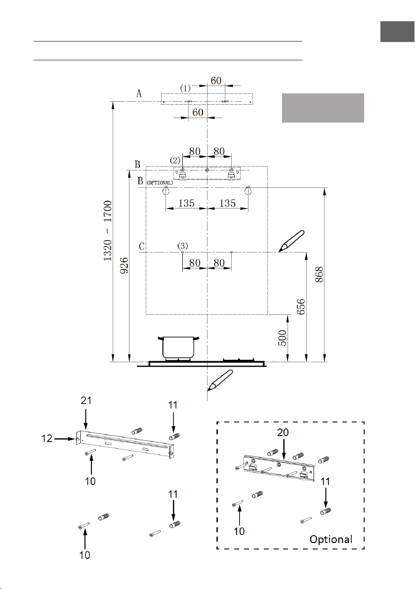
99
IT
INSTALLAZIONE
Nota: I valori
specicati sono in [mm].

100
IT
1° passaggio: posizionare correttamente il dispositivo
Tracciare le seguenti linee di riferimento nella zona di installazione:
• Una linea verticale no al softto o no al limite superiore dell‘area di installazione,
al centro dell‘area di montaggio della cappa.
(A) Una linea orizzontale A, 1320-1700 mm sopra il piano cottura.
(B) Una linea orizzontale B, almeno 926 mm (facoltativamente 868 mm) sopra il piano
cottura.
(C) Una linea orizzontale C, almeno 656 mm sopra il piano cottura.
2° passaggio: segnare i fori
• Segnare un punto (1) sulla linea orizzontale A, 60 mm a destra della linea di
riferimento verticale.
• Ripetere questa procedura sull‘altro lato e vericare che i due segni siano alla
stessa altezza.
• Segnare un punto (2) sulla linea orizzontale B, 80 mm (facoltativamente 135 mm)
a destra della linea di riferimento verticale.
• Ripetere questa procedura sull‘altro lato e sulla linea di riferimento verticale e
vericare che i tre segni siano alla stessa altezza.
• Segnare un punto (3) sulla linea orizzontale C, 80 mm a destra della linea di
riferimento verticale.
• Ripetere questa procedura sull‘altro lato e vericare che i due segni siano alla
stessa altezza.
3° passaggio: ssare le staffe (facoltativo)
• Praticare i fori per le viti nei punti contrassegnati (1) (2) (3) utilizzando un trapano
da Φ10 mm.
• Inserire i tasselli (11) nei fori (1) (2) (3).
• Fissare la staffa di ssaggio della cappa aspirante (20) con 3 viti 5 x 50 (10) in
dotazione.
• Fissare la staffa di ssaggio del rivestimento del camino (21) con 2 viti 5 x 50 (10)
in dotazione.

101
IT
4° passaggio: agganciare il corpo del dispositivo
• Aprire il pannello frontale (pannello di controllo).
• Rimuovere il ltro antigrasso metallico utilizzando le maniglie in dotazione.
• Il corpo del dispositivo può essere agganciato in due punti diversi:
1 Agganciare il corpo del dispositivo al supporto (20).
2 O ssare il corpo del dispositivo alle viti 5 x 50 (10) ai punti segnati con (2).
• Allineare il corpo del dispositivo in modo che rimanga appeso dritto.
Corretto Incorretto
• Accedendo dalla parte interna dell‘apparecchio, avvitare le viti (10) nei tasselli
(11) nei punti segnati con (3).
• Inserire il ltro nella cappa aspirante.
• Chiudere il pannello frontale (pannello di controllo).
Installazione con il sistema di aspirazione
5° passaggio: collegare la cappa di aspirazione all‘impianto di scarico.
• Collegare la cappa al sistema di scarico dell‘aria durante l‘installazione. Utilizzare
un tubo essibile o rigido con un diametro di 150 mm o 120 mm. La scelta del tubo
è a proprio piacimento.
• Se si sceglie un raccordo per l‘aria di scarico da 120 mm, ssare anche la angia
(3) all‘apertura del corpo del dispositivo.
• Fissare il tubo di scarico (4) nella posizione corretta e con un numero sufciente di
fascette (non incluse).
• Rimuovere eventuali ltri a carboni attivi all‘interno.
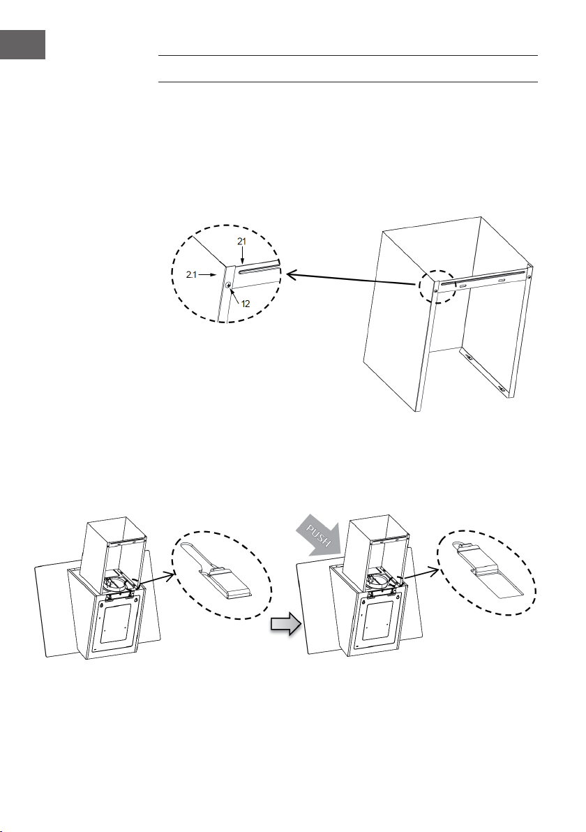
102
IT
INSTALLAZIONE DEL SISTEMA DI SCARICO
Il sistema di scarico può essere montato solo in combinazione con una cappa
Rivestimento inferiore del camino
• Montare una staffa di ssaggio (21) sul rivestimento inferiore del camino con 2 viti
4,2 x 9,5 (12) in dotazione.
• Premere leggermente i due lati del rivestimento inferiore del camino e agganciarli
al corpo della cappa. Assicurarsi che il rivestimento del camino sia ben ssato.
103
IT
Rivestimento superiore del camino
• Allargare leggermente i due lati del pannello superiore del camino e appenderli tra
la parete e la staffa (21) ssata al rivestimento inferiore del camino.
• Fissare il rivestimento superiore del caminetto alla staffa (21) con 2 viti 4,2 x 9,5
(12) in dotazione.

104
IT
PANNELLO DI CONTROLLO
Opzionale:
Pulsante Funzione
Accensione: premere questo pulsante per accendere o spegnere.
Spegnimento ritardato: il pulsante lampeggia
• Se si preme una volta il pulsante di accensione, questo
lampeggia e l‘apparecchio si spegne dopo 3 minuti.
• Premere nuovamente il pulsante e l‘apparecchio si spegne
immediatamente.
Controllo della velocità: se si preme questo pulsante, il dispositivo
funziona a bassa velocità.
Controllo della velocità: se si preme questo pulsante, il dispositivo
funziona a media velocità.
Controllo della velocità: se si preme questo pulsante, il dispositivo
funziona ad alta velocità.
Luce accesa/spenta: premere questo pulsante per accendere e
spegnere la luce.
Aumento di velocità: premere questo pulsante per far funzionare il
dispositivo a velocità maggiorata.
(opzionale)

105
IT
PULIZIA E MANUTENZIONE
Apertura e pulizia del pannello frontale
• Premere sul pannello frontale e tirarlo in avanti per aprirlo.
• Pulire l‘esterno e l‘interno con un panno umido e un detergente neutro. Non
utilizzare mai panni bagnati, spugne, acqua corrente, idropulitrici o detergenti
abrasivi.
Pulizia dei ltri antigrasso
• A seconda della frequenza di utilizzo, i ltri
antigrasso devono essere puliti almeno ogni 2
mesi o più. I ltri sono lavabili in lavastoviglie.
• Tirare il rivestimento per aprirlo.
• Togliere i ltri premendoli contro il retro della
cappa e tirandoli contemporaneamente verso
il basso.
• Assicurarsi che i ltri non si pieghino durante
la pulizia. Prima di reinserire i ltri, assicurarsi che siano completamente asciutti.
(Il colore della supercie del ltro può cambiare nel tempo. Tuttavia, questo non
inuisce in alcun modo sulla sua efcacia).
• Accertarsi di reinserire correttamente i ltri dopo la pulizia, con la maniglia rivolta
verso l‘esterno.
Filtro ai carboni attivi (versione con ricircolo dell‘aria)
• Questi ltri non possono essere lavati e riutilizzati.
I ltri ai carboni attivi devono essere sostituiti almeno ogni 4 mesi o più, a seconda
della frequenza di utilizzo.
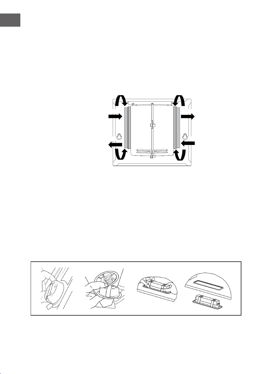
106
IT
Sostituzione del ltro ai carboni attivi
1 Aprire il pannello e tirarlo verso il basso.
2 Rimuovere i ltri antigrasso metallici.
3 Rimuovere il ltro ai carboni attivi da sostituire.
4 Inserire un nuovo ltro ai carboni attivi.
5 Reinserire i ltri antigrasso metallici.
6 Richiudere il pannello.
Fissare Rimuovere
Rimuovere
Fissare
Sostituzione dell‘illuminazione (lampada a LED da 1,5 W)
• Spegnere la cappa di aspirazione e scollegare l‘alimentazione elettrica
dell‘apparecchio (estrarre la spina di alimentazione o spegnere il fusibile).
• Rimuovere il ltro antigrasso.
• Rimuovere il modulo di luci LED allentando l‘attacco luce dall‘alloggiamento del
dispositivo (potrebbe essere necessario esercitare una certa pressione o forza).
• Scollegare il collegamento tra il terminale e la luce LED.
• Sostituire la lampada con un‘altra a LED dello stesso tipo disponibile in commercio
(1,5W). Assicurarsi di ricollegare correttamente la luce LED.
• Reinserire il modulo luci nell‘alloggiamento dell‘apparecchio.

107
IT
Luce di ricambio
Ø Potenza Tensione Figura
Codice
ILCOS D
70 mm 1,5 W DC 12 V
DSR-
1.5-S-70
33,2 mm
x 120mm
1.5 W DC 12 V
DSS-1.5-
S-33.2
/ 120
RISOLUZIONE DEI PROBLEMI
Problema Causa Soluzione
Le luci sono accese, ma il
motore non funziona.
Le lame sono bloccate. Controllare le lame.
Il condensatore è
danneggiato.
Sostituire il condensatore.
Il motore è danneggiato. Sostituire il motore.
Il cablaggio interno del
motore è interrotto/
difettoso. Potrebbe
causare un odore
sgradevole.
Sostituire il motore.
La luce e il motore non
funzionano.
Oltre a quanto sopra, controllare quanto segue:
La luce è danneggiata. Sostituire la luce.
Il cavo di alimentazione è
allentato.
Collegare i collegamenti
elettrici secondo lo
schema elettrico.
Perdite di olio L'ingresso e l'uscita
dell'aria non sono sigillati
correttamente.
Rimuovere l'uscita e
sigillarla con la colla.
Il collegamento tra il
prolo a U e il rivestimento
presenta delle perdite.
Sigillare il collegamento
con un agente adatto.

108
IT
Problema Causa Soluzione
Vibrazione Se le lame sono bloccate,
possono causare
vibrazioni.
Sostituire le lame.
Il motore non è montato
correttamente.
Montare correttamente il
motore.
La cappa non è ssata
correttamente.
Fissare correttamente la
cappa.
Insufciente aspirazione
dell'aria
Il piano cottura è troppo
distante dalla cappa.
Regolare nuovamente la
distanza.
Troppa corrente d'aria
attraverso porte o nestre
aperte.
Installare il dispositivo in
una nuova posizione o
chiudere porte e nestre.
Il dispositivo è inclinato in
avanti.
Le viti di ssaggio non
sono state serrate a
sufcienza.
Serrare le viti e allineare la
cappa orizzontalmente.
Le viti della staffa non
sono state serrate a
sufcienza.
Serrare le viti e allineare la
cappa orizzontalmente.

109
IT
AVVISO DI SMALTIMENTO
Se nel proprio paese si applicano le regolamentazioni
inerenti lo smaltimento di dispositivi elettrici ed elettronici,
questo simbolo sul prodotto o sulla confezione segnala che
questi prodotti non possono essere smaltiti con i riuti normali
e devono essere portati a un punto di raccolta di dispositivi
elettrici ed elettronici. Grazie al corretto smaltimento dei
vecchi dispositivi si tutela il pianeta e la salute delle persone
da possibili conseguenze negative. Informazioni riguardanti il
riciclo e lo smaltimento di questi prodotti si ottengono presso
l’amministrazione locale oppure il servizio di gestione dei
riuti domestici.
PRODUTTORE E IMPORTATORE (UK)
Produttore:
Chal-Tec GmbH, Wallstraße 16, 10179 Berlino, Germania.
Importatore per la Gran Bretagna:
Chal-Tec UK limited
Unit 6 Riverside Business Centre
Brighton Road
Shoreham-by-Sea
BN43 6RE
United Kingdom

110
IT
SCHEDA DATI DEL PRODOTTO
Indicazioni conformi alla direttiva (UE) N° 65/2014
Metodi di misurazione e calcolo conformi a EN 61591:1997+A1:2006+A2:2011+A11:
2014+A12:2015
Numero articolo
10033707, 10033708
Denizione Simbolo Valore Unità
Consumo energetico annuale AEC
hood
91,8 kWh/Anno
Classe di efcienza energetica C
Efcienza uidodinamica FDE
hood
18,1
Classe di efcienza uidodinamica D
Efcienza luminosa LE
hood
41 Lux/W
Classe di efcienza luminosa A
Grado di separazione del grasso GFE
hood
77,3 %
Classe relativa al grado di
separazione del grasso
C
Flusso d’aria a velocità minima in
funzionamento normale, escluso il
funzionamento a livello intenso o
ad alta velocità.
285,7 / 624,7 m³/h
Flusso d’aria in funzionamento
intenso o ad alta velocità.
- m³/h
Livello di emissioni sonore
ponderato A, nelle velocità
massima e minima disponibili in
funzionamento normale.
49 / 66 dB
Livello di emissioni sonore
ponderato A, in funzionamento
intenso o ad alta velocità.
- dB
Potenza assorbita a dispositivo
spento
P
o
0.0 W
Potenza assorbita a dispositivo in
standby
P
s
0.44 W
Informazioni di contatto Chal-Tec GmbH, Wallstraße 16, 10179, Berlino,
Germania

111
IT
Indicazioni conformi alla direttiva (UE) N° 66/2014
Metodi di misurazione e calcolo conformi a EN 61591:1997+A1:2006+A2:2011+A11:
2014+A12:2015
Numero articolo
10033707, 10033708
Denizione Simbolo Valore Unità
Consumo energetico annuale AEC
hood
91,8 kWh/Anno
Fattore di incremento nel tempo f 1,3
Efcienza uidodinamica FDE
hood
18,1
Indice di efcienza energetica EEI
hood
76,0
Volume del usso d’aria misurato
nel punto di massima efcienza
Q
BEP
362,0 m³/h
Pressione dell’aria misurata nel
punto di massima efcienza
P
BEP
340 Pa
Flusso d’aria massimo Q
max
624,7 m³/h
Potenza elettrica in entrata
misurata nel punto di massima
efcienza
W
BEP
188,8 W
Potenza nominale del sistema di
illuminazione
W
L
3 W
Intensità luminosa media del
sistema di illuminazione sul piano
cottura
E
middle
124 Lux
Potenza assorbita misurata a
dispositivo in standby
P
o
0.0 W
Potenza assorbita misurata a
dispositivo spento
P
s
0.44 W
Livello di rumorosità L
WA
66 dB
Informazioni di contatto Chal-Tec GmbH, Wallstraße 16, 10179, Berlino,
Germania


