Loading ...
Loading ...
Loading ...
For Customer Service, call 800-377-7655.
7
FOLLOW THESE EASY STEPS:
• Make sure the material into which you plan to mount the
speakers (plaster, drywall, paneling, stone, etc.) can support
the weight of the speakers (see specification page for the
weight of your model).
• Make sure the locations you select do not conceal studs, elec-
t
rical wiring or plumbing. Prior to installation, hold the speaker
in your chosen location to make sure it safely clears obstacles
such as studs, corners, beams, lighting fixtures and door/win-
dow frames. Your cutout must be at least 1" (25mm) from
adjoining walls or ceiling, internal studs or plumbing.
• Using the template, trace the installation location with a pen-
cil. You can do this by holding the template in your preferred
location and tracing around it (rectangle)
or within the template pop-out area (round). Use a level to
make certain the template is straight and plumb. This is the
exact cutout size [figures 10a & 10b].
SUIVEZ CES SIMPLES ÉTAPE:
• Assurez-vous que le matériau dans lequel vous comptez
installer vos haut-parleurs (plâtre, placoplâtre, lambris, pierre,
etc.) peut supporter le poids des haut-parleurs (voir la fiche
technique pour le poids du modèle de vos haut-parleurs).
• Assurez-vous que l’endroit choisi pour l’installation murale ne
dissimule pas de montants ou de solives, de fils électriques ou
de plomberie. Avant son installation, tenez le haut-parleur à
l’endroit choisi pour vous assurer qu’il soit suffisamment
dégagé du plafond, des murs, des coins, des poutres, des lumi-
naires et des cadres de portes et de fenêtres. L’embrasure doit
être à au moins 1 pouce (25mm) du mur ou du plafond adja-
cent, d’un montant ou d’une solive, ou de plomberie.
• À l’aide du gabarit, tracez l’endroit de l’installation avec un crayon.
V ous pouvez accomplir cette tâche en tenant le gabarit sur l’endroit
choisi et en traçant autour (rectangle) ou en traçant à l’intérieur de la
zone détachable du gabarit (rond). Utilisez un niveau pour vous assurer
que le gabarit est bien droit et de niveau. C’est la grandeur exacte de
l’embrasure [figures 10a & 10b].
• Carefully cut the hole with the appropriate cutting tool for your
wall or ceiling material. Start the hole by drilling a hole on the
inside of the tracing (with the drill bit touching the line). Use
this hole to insert the saw or knife and begin cutting [figure 11].
• Once you have cut the hole, fish your previously positioned
wiring out of the hole and connect the speaker. Follow the
hookup directions included with your receiver. Strip 2 inch (12
mm) of insulation from each of the two conductors of the wire
to expose the bare metal and twist each of the conductors into
a single unfrayed strand (so you have two unfrayed strands).
Note that one of the terminals on the rear of each speaker is
red (+) and the other is black (-). Make certain that you connect
the wire from the red terminal (+) of your amplifier or receiver
to the red terminal (+) on your speaker and the wire from the
black terminal (-) of your amplifier or receiver to the black ter-
minal (-) on your speaker. Most wire has some indicator (such
as color -coding, ribbing or writing) on one of the two conduc-
tors to help you maintain consistency [figure 12].
• Découpez soigneusement l’embrasure avec l’outil approprié au
matériau de votre mur ou plafond. Commencez l’opération en
faisant un trou à l’intérieur du traçage (la mèche touchant le
traçage). Utilisez ce trou pour insérer la scie ou le couteau et
commencer le découpage [figure 11].
• Une fois l’embrasure pratiquée, sortez-en le câble précédem-
ment installé et connectez-le au haut-parleur. Suivez les
instructions de raccordement fournies avec votre récepteur.
Retirez 12 mm (1/2 po) d’isolation de chacun des deux conduc-
teurs pour exposer les brins métalliques et tordez les brins de
chaque conducteur pour former deux torons non éraillés. Notez
qu’une des bornes à l’arrière de chaque haut-parleur est rouge
(+) et l’autre noire (-). Assurez-vous de bien raccorder le fil
provenant de la borne rouge (+) de votre amplificateur /récep-
teur à la borne rouge (+) de votre haut-parleur et le fil noir (-)
provenant de la borne noire (-) de votre amplificateur/récepteur
à la borne noire (-) de votre haut-parleur. La polarité de la plu-
part des fils à deux conducteurs est codée (couleur, nervure ou
écriture) pour faciliter son identification [figure 12].
FIGURE 11
Cut the hole with the appropriate tool.
Haga el corte con la herramienta apropiada.
Taillez l’ouverture avec l'outil approprié
Schneiden Sie die Öffnung mit dem
entsprechenden Werkzeug aus.
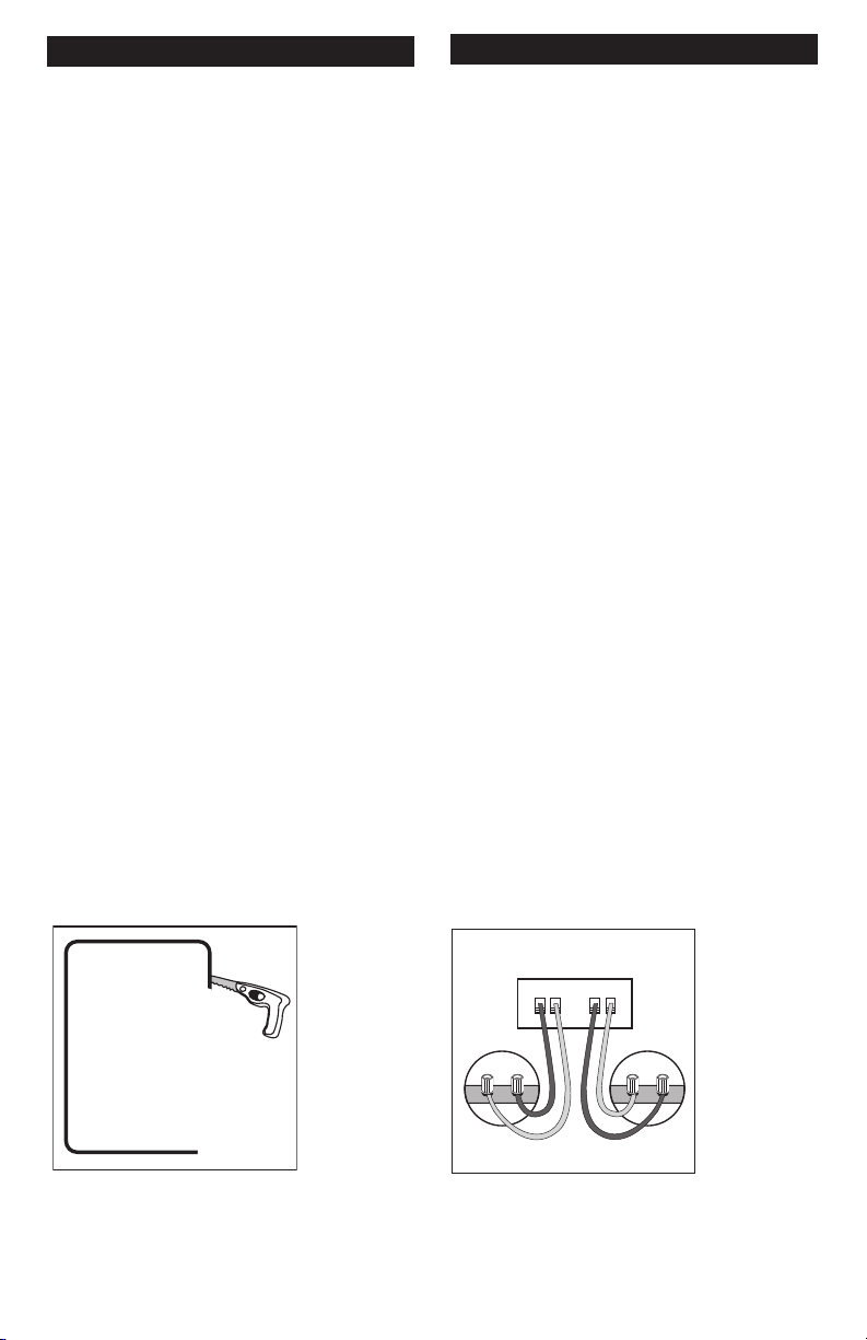
FIGURE 12
Hook up the speaker wires.
Conecte los cables de los altavoces.
Branchez les fils de haut-parleur.
Schließen Sie die Lautsprecherkabel an.
+
_
+
_
+
_
+
_
LEFT
AMP
RIGHT
Loading ...
Loading ...
Loading ...