Loading ...
Loading ...
Loading ...
En-3
● OPERATING INSTRUCTIONS ●
• Press CLOCK gently using a thin instrument.
• Make sure the polarity of the batteries is correct.
•
Do not use manganese batteries and leaking batteries. The remote controller
could malfunction.
• Do not use rechargeable batteries.
•
The battery replacement indicator lights up when the battery is running low. In
about 7 days after the indicator starts lights up, the remote controller stops working.
• Replace all batteries with new ones of the same type.
• Batteries can be used for approximately 1 year. However, batteries with
expired shelf lives last shorter.
• Press RESET gently using a thin instrument.
If the RESET button is not pressed, the remote controller may not operate
correctly.
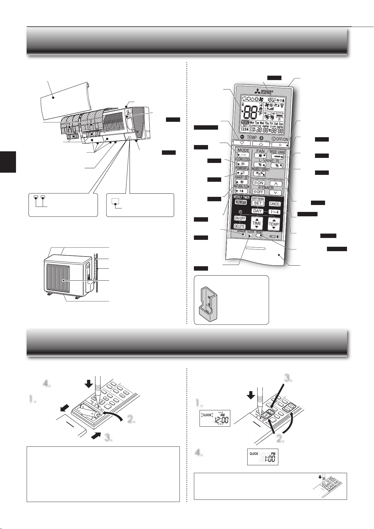
Before operation: Insert the power supply plug into the power outlet and/or turn the breaker on.
Operation indicator lamp
Remote control receiving
section
Emergency
operation
switch
Page 6
Horizontal
vane
Air inlet
Air fi lter
(Nano platinum
fi lter)
Air cleaning fi lter
(Electrostatic
anti-allergy
enzyme fi lter and
deodorizing fi lter)
Front panel
Installing the remote controller batteries
Setting current time
NAME OF EACH PART
PREPARATION BEFORE OPERATION
Indoor unit Remote controller
1.
Remove the front lid.
2.
Insert the negative
pole of AAA
alkaline batteries fi rst.
3.
Install the front lid.
4.
Press RESET.
1.
Press CLOCK.
4.
Press CLOCK again.
2.
Press either the TIME button
or the TIMER buttons to set
the time.
Each press changes the clock
1 minute forward/backward (10
minutes when pressed longer).
3.
Press the DAY button
to set the day.
Remote controller holder
Signal transmitting
section
Distance of signal :
About 20 ft. (6 m)
Beep(s) is (are) heard from
the indoor unit when the
signal is received.
Operation
display section
OFF/ON
(stop/operate) button
Temperature
buttons
Pages 4, 6, 8
Operation
select button
Page 6
ECONO COOL
button
Page 8
FAN speed control
button
Page 7
VANE control
button
Page 7
TIME, TIMER set buttons
Pages 3, 9
forward button
backward button
CLOCK button
Page 3
RESET button Pages 3, 4
Lid
Slide the lid down
to open the remote
controller. Slide it down
further to get to the
weekly timer buttons.
• Install the remote con-
troller holder in a place
where the signal can be
received by the indoor
unit.
• When the remote con-
troller is not used, place
it in this holder.
Only use the remote controller provid-
ed with the unit.
Do not use other remote controllers.
If two or more indoor units are installed
in proximity to one another, an indoor
unit that is not intended to be operated
may respond to the remote controller.
SMART SET
button
Page 8
WEEKLY TIMER
set buttons
Page 10
Air outlet
Outdoor unit
Outdoor units may be different in appearance.
Air inlet (back and side)
Refrigerant piping
Drainage hose
Air outlet
Drain outlet
WIDE VANE
button
Page 7
INDIRECT/DIRECT
button
Page 5
POWERFUL
button
Page 9
NATURAL
FLOW button
Page 9
SENSOR
(i-see) button
Page 5
i-see sensor Page 5
Battery replacement indicator Page 3
JG79A806H05_en.indd 3 2019/06/27 15:13:54
Loading ...
Loading ...
Loading ...