Loading ...
Loading ...
Loading ...
HOW TO CONVERT THE RANGE FOR
USE
WITH
LP
GAS OR NATURAL GAS
(continued)
5. To prevent leakage, make sure the orifice
spuds are securely screwed into the gas inlet
tubes. Use a small wrench to hold the inlet tube
hex to prevent it from twisting.
6. Put old orifice spuds back in the bag to save
for possible future conversion.
N~:
If an orifice spud is accidentally
dropped, the cooktop
can be raised by
“engaging
e
the 2 front clips
with a large flat
blade screwdriver.
DO NOT attempt to raise the cooktop without
removing
all
4 burner bases.
If wires were disconnected to remove the
cooktop, feed wires through the burner holes in
the cooktop. Attach to each burner electrode
terminal carefully, making sure not to bend the
terminal. Then lower cooktop until it snaps
over the clips.
Electrode
Tall Screw
7. Carefully insert burner bases straight down
with the tube over the
ortilce
spud. Replace the
screws,
mating
sure
the
Ml
screw is
opposite the burner electrode in each
burner base.
❑
CONVERTING SURFACE BURNERS OH
MODELS EQUIPPED WITH STANDARD TWIN
BURNERS
(See
Step 3 if range is equipped with
sealed burners.)
1.
Lift cooktop.
2. Lift burner
assemblies
straight up and set
aside to gain
access to surface
burner spuds.
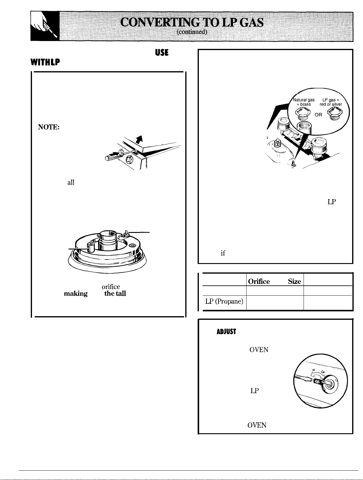
3. With a 5/16” or
small adjustable
wrench, remove
each of the four
‘~
/
spuds on the
surface burner gas inlet tubes and replace them
with the correct gas spuds mounted in a holder
at the right rear of the range, above the
regulator. Natural gas spuds are brass and
LP
gas spuds are red or silver. (Mount the spuds
that you removed from the inlet tubes back in
the holder.) To prevent leakage, make sure
spuds are securely screwed into gas inlet tubes.
4. Replace the burner assemblies.
5. Keep all spuds with your range so you have
them
H
you move or get a different gas hook-up.
Top Burner
Ofice
Drill
She
Color
Natural Gas
#54 (.0550 Dia.)
Brass
LP
@ropane)
#66 (.0330 Dia.)
Red or Silver
❑
ADJUST
OVEN THERMOSTAT
(for Models Equipped with Standing Pilots)
1. Remove the
OWN
CONTROL knob.
2. Locate the thermostat
-
.
adjustment screw at left of
thermostat shaft. Turn the
.-
screw until the small
pointer stops at
LP
or N,
depending on the type of gas
you are converting to. The
o
*
(&
‘“”””
-
%
J
most the screw will move is
1/2 a turn.
3. Replace the
OWN
CONTROL knob.
42
Loading ...
Loading ...
Loading ...