


2
ENGLISH
CONTENTS
OPEN SOURCE SOFTWARE NOTICE
INFORMATION --------------------------------------------3
ON CLEANING ---------------------------------------------3
GENERAL DESCRIPTION ---------------------------------3
PART NAME AND FUNCTION ---------------------------6
ASSEMBLING BATTERY --------------------------------11
REMOVING BATTERY ----------------------------------12
SPECIFICATION AND DIMENSION OF EACH
PART ------------------------------------------------------13
ENVIRONMENTAL REQUIREMENT -------------------20
CALIBRATION SOFTWARE INSTALL ----------------- 20
CONNECTION TYPES -----------------------------------21

3
ENGLISH
OPEN SOURCE SOFTWARE NOTICE
INFORMATION
To obtain the source code under GPL, LGPL, MPL, and other open source licenses, that is contained in this
product, please visit http://opensource.lge.com.
In addition to the source code, all referred license terms, warranty disclaimers and copyright notices are
available for download.
LG Electronics will also provide open source code to you on CD-ROM for a charge covering the cost of performing
such distribution (such as the cost of media, shipping, and handling) upon email request to
opensourc[email protected]om.
This offer is valid for a period of three years after our last shipment of this product. This offer is valid to anyone
in receipt of this information.
ON CLEANING
Recommended Cleaning Chemicals
• Isopropanol 70 %
• Ethanol 70 %
• Cidex® OPA
• 0.9 % NaCl solution
How to Use Cleaner
• Prior to cleaning, turn off the Detector and remove the power cable.
• Soak a soft cloth in a recommended cleaner, then lightly rub the screen with no more than 1 N of force.
• The cleaner could cause serious damage if it leaks inside the Detector while cleaning.
• Do not use benzene, thinner, acids or alkaline cleaners or other such solvents.
• Cleaning guidelines for Detector must only be carried out by medical professionals (doctors or nurses) and
must not be handled by patients.
GENERAL DESCRIPTION
Overview
This model is an x-ray imaging device, a system that can acquire and process X-ray images as digital images. It
utilizes amorphous silicon and a high-performance scintillator to ensure sharp high-definition image quality
with the resolution of 3.6 lp/mm and the pixel pitches of 140 um. This device is a flat panel based X-ray image
acquisition device. This device must be used in conjunction with an operating PC and an X-ray generator. This
device can be used for digitizing and transferring X-ray images for radiological diagnosis. The data transmission
between the Detector and PC can be enabled with a wired (cable) or wireless connection.
Product Component
• Detector: 17HK701G
• Control Box:
- AC power cord for Control Box
• Battery Charger:
• 2 Battery (LBQ7222L)
• AC Power adapter for Charger (DA-65J19)
• AC Power cord for AC Power adapter
• Cable
- Main Cable: Detector and Control Box link cable (Supply DC power, Ethernet data, control signals of X-ray
Generator)
- Trigger Cable: X-ray Generator to Control Box, transmit control signal between Detector and X-ray
Generator. (Optional)
- LAN Cable: Control Box to PC, exchanges Ethernet data between PC and Detector. (Optional)
• CD: Owner's Manual,
• Regulatory Manual, Inspection Report
4
ENGLISH
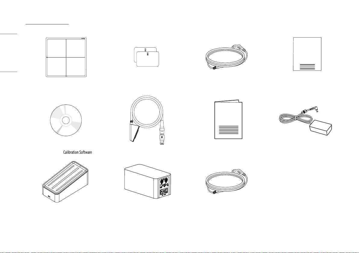
Basic Accessories
100kg
Detector 1 EA Battery 2 EA AC Power cord for AC Power adapter 1 EA Inspection Report 1 EA
CD (Owner's Manual / ) 1 EA Main Cable 1 EA Regulatory Manual 1 EA AC Power adapter for Charger 1 EA
Charger 1 EA Control Box 1 EA AC Power cord for Control Box 1 EA
5
ENGLISH
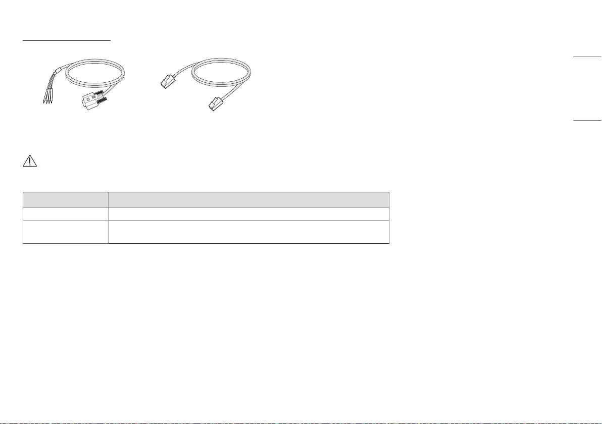
Optional Accessories
Trigger Cable 1 EA LAN Cable 1 EA
• Some models may not include additional accessories.
CAUTION
• You must use the authorized components as per the specification below. Unauthorized components may cause damage and/or cause the product to malfunction.
Component Standard
LAN Cable More than CAT5E Standard
Power Cord US – Approved Medical grade regulation
Others – Approved country safety regulation
• The AC/DC adapters etc. that are being used, with the exception of the upper components, must be supplied by the manufacturer.
6
ENGLISH
PART NAME AND FUNCTION
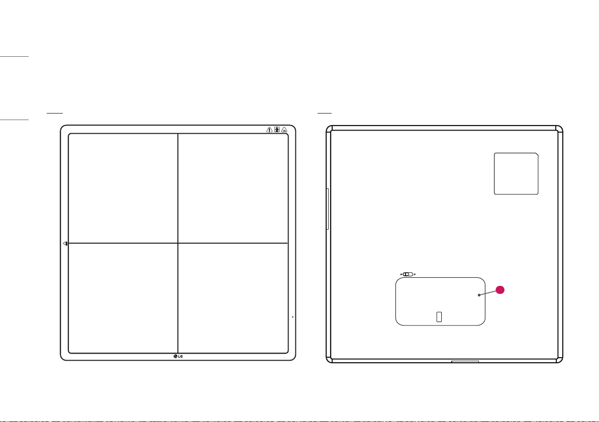
Detector
Front Back
100kg
1
7
ENGLISH
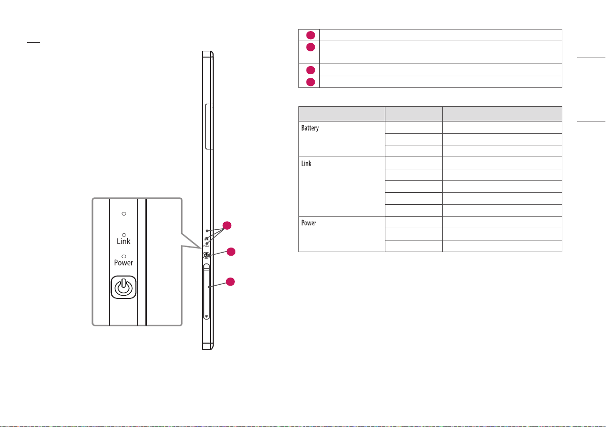
Side
Battery
Battery
3
2
4
1
Battery
2
Power Button: Power on/off switch
(On: press over 1 sec, Off: press over 5 sec)
3
LED Indicator: Indicating Detector’s status
4
Connection to Main Cable
LED LED Color Status
Green Battery is more than 30 % charged.
Orange Battery charging status is 10 ~ 30 %.
Orange Blinking Battery is less than 10 % charged.
Green Ethernet/Wireless(Station) connection
Green Blinking Wireless(Station) disconnected
White Wireless(AP) connection
White Blinking Wireless(AP) disconnected
Off Ethernet disconnected
Green Power On
Green Blinking Sleep mode
Off Power Off
8
ENGLISH
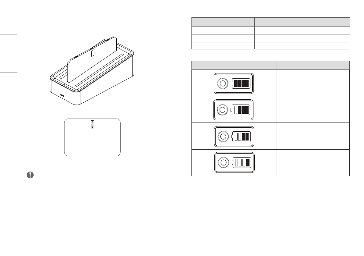
Battery and Charger
NOTE
• Battery: Li-ion polymer battery (Charging time - Typ. 4 hours)
• Battery pack itself shows the remaining battery percentage.
• Battery charger: 3 ports cradle type
• LED Indicator: Following LEDs are located to each battery.
LED Indicator Status
Green Completion of charging
Orange On charging
Orange Blinking Error (Connection error, etc)
Battery Remain Indicator Battery Level
75 ~ 100 %
50 ~ 75 %
25 ~ 50 %
0 ~ 25 %
9
ENGLISH
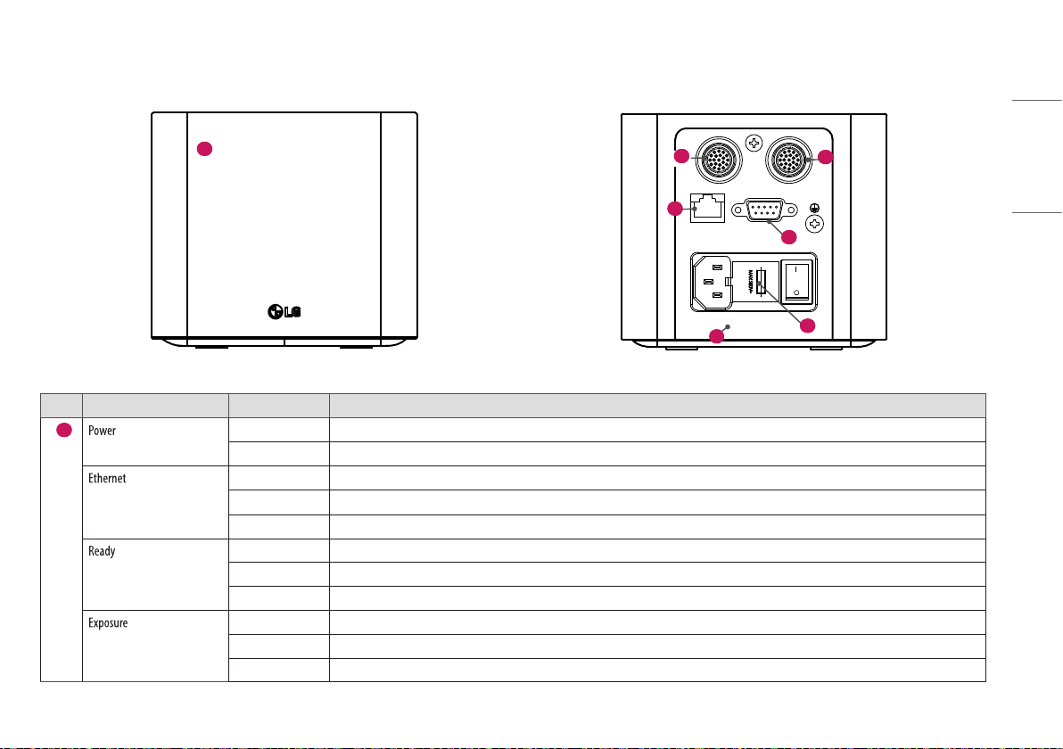
Control Box
AC-IN T4L 250V
Ethernet Sync
DXD 1 DXD 2
Power Ethernet Ready Exposure
1
AC-IN T4L 250V
Ethernet Sync
DXD 1 DXD 2
Power Ethernet Ready Exposure
7
5
2
3
6
4
No. LED Indicator LED Color Status
1
Green Power normal operation
Off Power off (AC power cord no connection or Power error)
Green Ethernet normal operation
Green blink On data communication
Off Ethernet disconnected
Green Ready signal from X-ray Generator is active
Off Ready signal from X-ray Generator is inactive
Orange blink Power error
Orange Exposure signal from X-ray Generator is active
Off Exposure signal from X-ray Generator is inactive
Orange blink Power error
10
ENGLISH
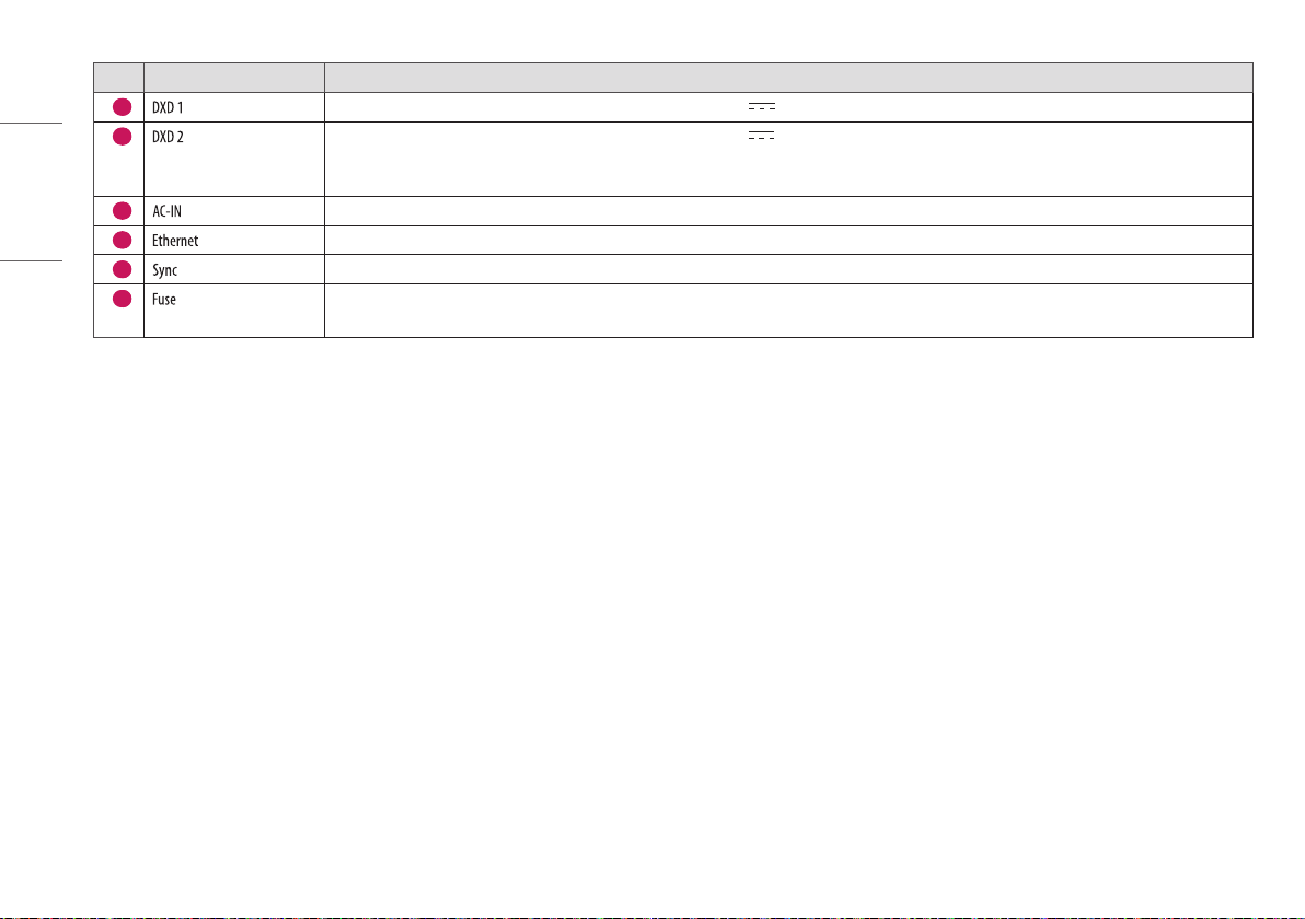
No. LED Indicator Status
2
Connecting the Control Box and the detector A. This connector supply power (24 V 2.1 A) to the detector, transmits X-ray synchronization signals and Ethernet image data.
3
Connecting the Control Box and the detector B. This connector supply power (24 V 2.1 A) to the detector, transmits X-ray synchronization signals and Ethernet image data.
Control Box supports 2 Detector connection. Usage is, one is for bucky stand, the other is for table(bed). Generally, X-ray room of hospital installs 2 detectors, bucky stand and table
type, it's for more convenient and efficient working environment. These 2 detectors are not operated simultaneously, control box selects the operating detector by AWS command.
4
Connects AC power cord
5
Ethernet port to transmit image/command between the detector and PC
6
This is to synchronize the detector and X-ray Generator
7
Control box power fuses are 4A, 250V to Type T fuse.
Power rating: T4L 250V
11
ENGLISH
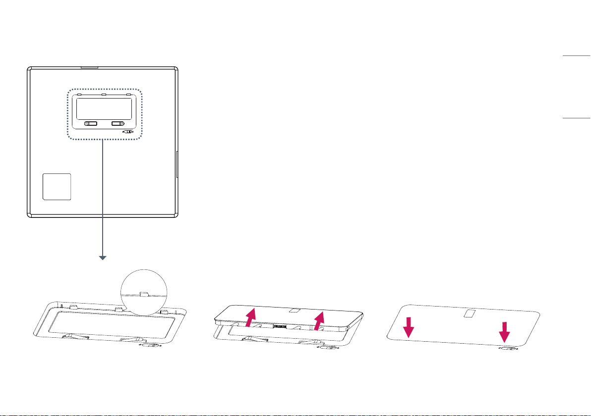
ASSEMBLING BATTERY
1 Check the battery mounting hole direction. 2 Insert into the hole on the side with the indicator. 3 Press the opposite side to secure the battery indicator.
12
ENGLISH
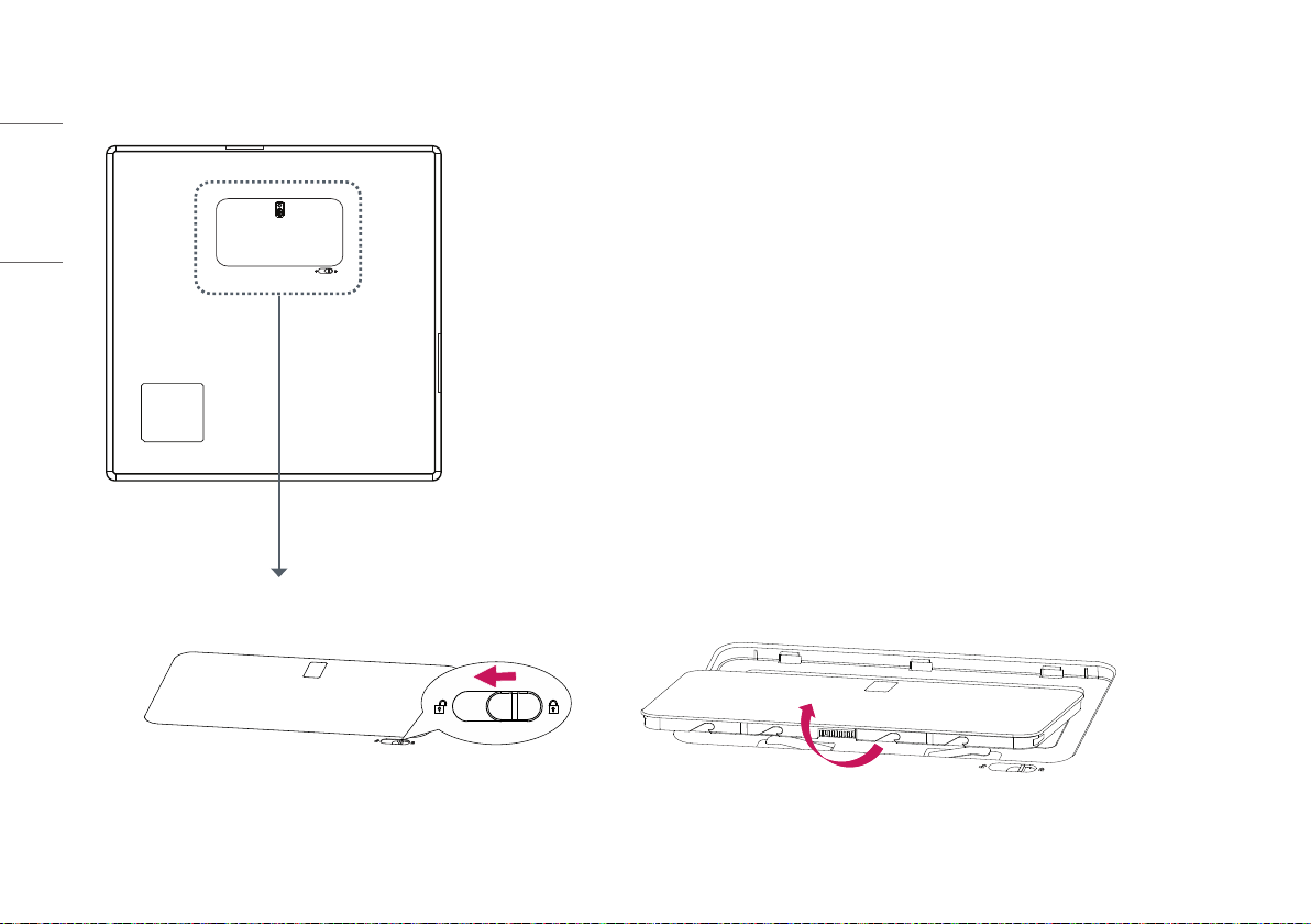
REMOVING BATTERY
1 Push the battery lock button in the direction of the picture. 2 Remove the battery by lifting it in the direction of the picture.
13
ENGLISH
SPECIFICATION AND DIMENSION OF EACH
PART
The product specifications are subject to change without prior notice for product improvements.
~ refers to alternating current (AC), refers to direct current (DC).
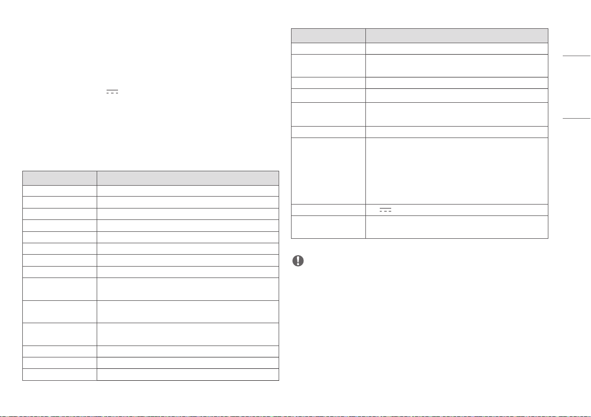
Specifications
Detector
Category Specifications
Model 17HK701G
Sensor Type Amorphous Silicon TFT
Scintillator Type CsI:TI
Total Pixel Matrix 3072 x 3072 pixels
Total Pixel Area 430.08 mm x 430.08 mm
Pixel Pitch 140 um
Effective Pixel Matrix 3060 x 3060 pixels
A/D Conversion 16 bit
Data transmission 802.11 a/b/g/n/ac Wireless LAN Standard, 150 Mbps
Wired Gigabit Ethernet Standard, 500 Mbps
Cycle time Typ. 8 Sec (Wired)
Typ. 11 Sec (Wireless)
Image Transmission Typ. 2 Sec (Wired)
Typ. 2.5 Sec (Wireless)
Image Storage Stores up to 200 images
Energy Range 40 kVP ~ 150 kVp
MTF Typ. 89 % at 0.5 lp/mm
Category Specifications
DQE Typ. 72 % at 0.1 lp/mm
Size (Width x Height x Depth) 460.0 x 460.0 x 15.6 mm
(18.1 x 18.1 x 0.6 inch)
Weight Typ. 3.6 kg (7.9 lbs)
Window Materials Carbon Fiber
Trigger Mode Manual Mode
Auto Mode (Auto Exposure Detection)
Power Consumption Typ. 30.5 W (For shooting)
Wireless Standard:
802.11 a/b/g/n/ac compliance
Peak mode: 867 Mbps
Frequency: 2.4 GHz / 5 GHz
Bandwidth: 20 MHz / 40 MHz / 80 MHz
MIMO: 2X2
Rating 24 V 2.1 A
Applied part Type: BF
Location: The front side of the detector (Effective area only)
NOTE
• Maximum wireless signal rate derived from IEEE standard specifications. Actual data throughput will vary.
Network conditions and environmental factors, including volume of network traffic, building materials and
construction, and network overhead, lower actual data throughput rate.
• Recommended Maximum operable distance: 2 m (6.5 ft) (From the Access Point)
• Wireless antennas: The module adopts the latest 802.11ac technology. The transmitter of the module is
powered by host equipment (Detector). The antennas are 2 printed-dipole antennas.
• Wireless module: 802.11 a/b/g/n/ac USB2.0 module is implemented. It supports 2T2R (2 transmit 2 receive)
MIMO technology, which delivers throughput up to 300 Mbps.
• Images can be saved by the X-ray generator while the power of the detector is turned on without connecting
to a PC. To produce images, X-ray is irradiated at intervals of more than 10 seconds. Check and load the saved
images from LG Acquisition Workstation Software.
14
ENGLISH
Detector has been tested with below table’s X-ray condition. This table is only for reference. The legally certified
radiologist expert should control X-ray dose.
Adult
SID (Inch / Cm) Tube Voltage (KV) Tube Current (mA) Tube Current x Time
(mAs)
Chest P-A 72 inch / 182.8cm 120 KV 250 mA 2.5 mAs
C-spine LAT 72 inch / 182.8cm 70 KV 200 mA 10 mAs
L-spine A-P 40 inch / 101.6cm 75 KV 320 mA 20 mAs
Abdomen A-P 40 inch / 101.6cm 75 KV 320 mA 10 mAs
Pelvic A-P 40 inch / 101.6cm 70 KV 320 mA 16 mAs
Wrist A-P 40 inch / 101.6cm 55 KV 100 mA 2.5 mAs
Elbow A-P 40 inch / 101.6cm 55 KV 100 mA 3.2 mAs
Shoulder AP 40 inch / 101.6cm 70 KV 200 mA 6.4 mAs
Foot A-P 40 inch / 101.6cm 58 KV 100 mA 2.5 mAs
Ankle A-P 40 inch / 101.6cm 59 KV 100 mA 3.2 mAs
Knee A-P 40 inch / 101.6cm 58 KV 100 mA 6.4 mAs
Regarding paediatric dosage, it should be much less than for an adult. The certified radiologist should pay
special attention to paediatric X-ray dosage levels.
GRID
Item Recommended Specification
SID 100 cm / 130 cm / 150 cm / 180 cm
(39.3 inch / 51.1 inch / 59 inch / 70.8 inch)
Size 460 x 460 mm
(18.1 x 18.1 inch)
Ratio 10 : 1
Frequency 215 Line / Inch
Inter Spacer AL
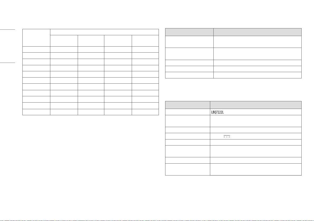
Battery
Item Specification
Model
Size (Width x Height x Depth) 204.6 x 110.5 x 7.8 mm
(8.0 x 4.3 x 0.3 inch)
Weight Typ. 0.24 kg (0.5 lbs)
Output Nominal voltage Typ. 7.5 V
Operation Temp 10 °C (50 °F) ~ 35 °C (95 °F)
Charging time 4 hours (standard) when charging with the Detector.
3 hours (standard) when charging two batteries with the charger.
Capacity Typ. 4000 mAh, Min. 3850 mAh
Battery performance Typ. 240 shots/6 hours
Min. 160 shots/4 hours (Cycle time 90 Sec, with Full charged battery)
15
ENGLISH
Battery Charger
Item Specification
Model
Size
(Width x Height x Depth)
125.0 x 90.0 x 255.0 mm
(4.9 x 3.5 x 10.0 inch)
Weight Typ. 0.9 kg (1.9 lbs)
Input 19 V 3.42 A
Output Nominal voltage 8.7 V
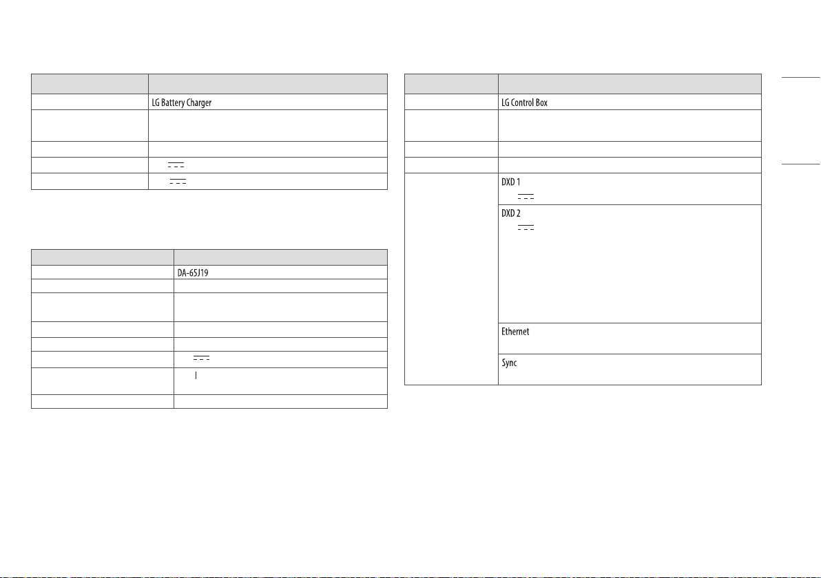
Battery Charger Adapter
Item Spec
Model
Manufacturer Asian Power Devices Inc. (APD)
Size (Width x Height x Depth) 134.0 x 59.8 x 31 mm
(5.2 x 2.3 x 1.2 inch)
Weight Typ. 0.3 kg (0.6 lbs)
Input AC 100-240 V~ 50-60 Hz, 1.5 A-0.7 A
Output 19 V 3.42 A
Classification by protection type against
Electric Shock
Class equipment
Cable length 1.5 m (4.9 ft)
Control Box
Item Specification
Model
Size (Width x Height x
Depth)
125.0 x 109.8 x 255.0 mm
(4.9 x 4.3 x 10.0 inch)
Weight Typ. 1.3 kg (2.8 lbs)
Input AC 100-240 V~ 50/60 Hz, 1.4-0.7 A
Output
24 V 2.1 A, Trigger signals, Ethernet data for Detector A.
24 V 2.1 A, Trigger signals, Ethernet data for Detector B.
Control Box supports 2 Detector connection.
Usage is, one is for Bucky stand, the other is for table (bed).
Generally, X-ray room of hospital installs 2 Detectors, Bucky stand and table
type, it's far more convenient and efficient working environment.
These 2 Detectors are not operated simultaneously, control box selects the
operating Detector by AWS command.
Transmission image/command between the Detector and PC.
Transmission control signals between the Detector and X-ray Generator.
16
ENGLISH
Cables
Item Length Qty
Main Cable 7 m (22.9 ft) 1
LAN cable (optional) 10 m (32.8 ft) 1
Power cord (110 V or 220 V) 1.5 m (4.9 ft) 2
Trigger Cable (Optional) 15 m (49.2 ft) 1
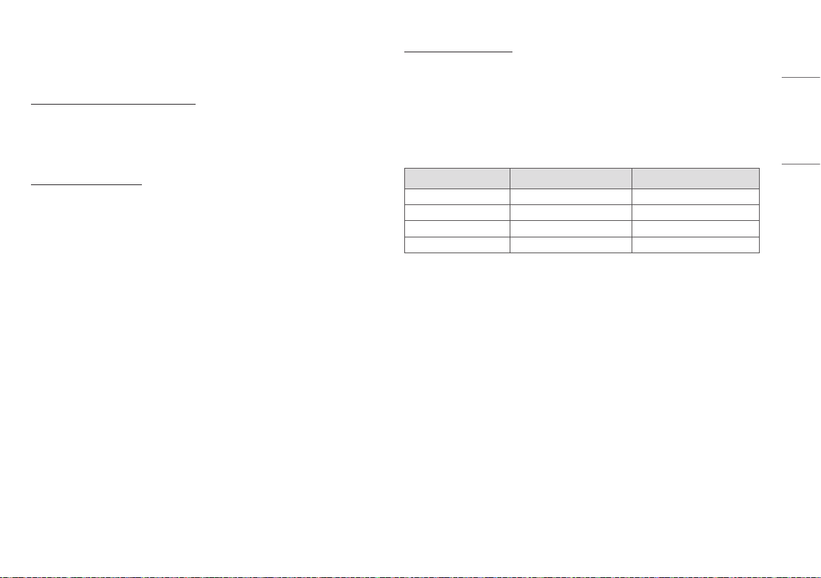
Wireless module (LGSWFAC73) Specifications
Wireless LAN (IEEE 802.11a/b/g/n/ac)
Frequency Range Output power (Max.)
2400 to 2483.5 MHz
5150 to 5725 MHz
5725 to 5850 MHz
17.4 dBm
17.8 dBm
15.6 dBm
• As band channels can vary per country, the user cannot change or adjust the operating frequency. This
product is configured for the regional frequency table.
• FCC ID: BEJLGSWFAC73 / IC: 2703H-LGSWFAC73
17
ENGLISH
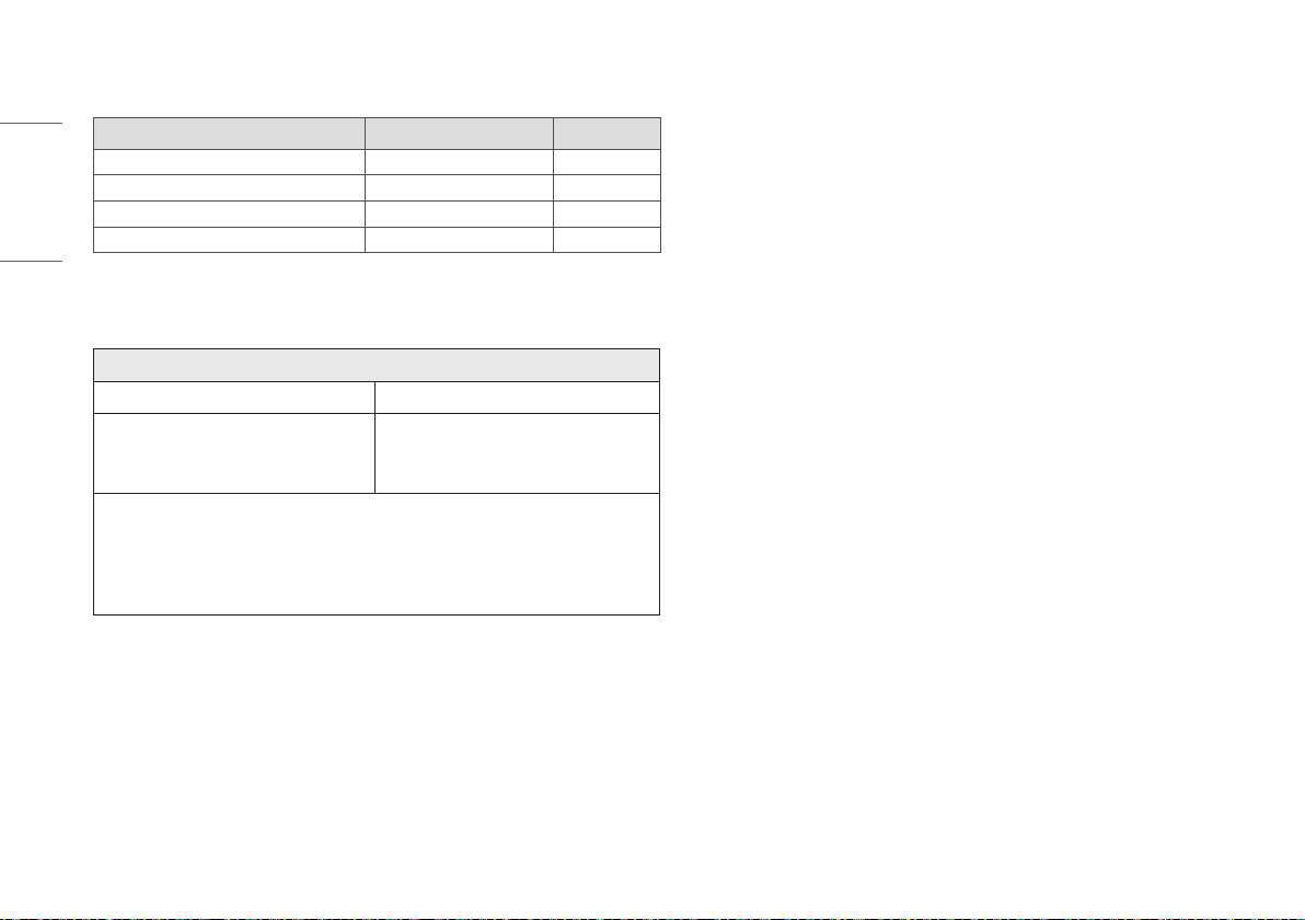
Dimension
Detector
Unit: mm (inch)
Front Side
100kg
460.0 (18.1)
460.0 (18.1)
100kg
15.6 (0.6)
18
ENGLISH
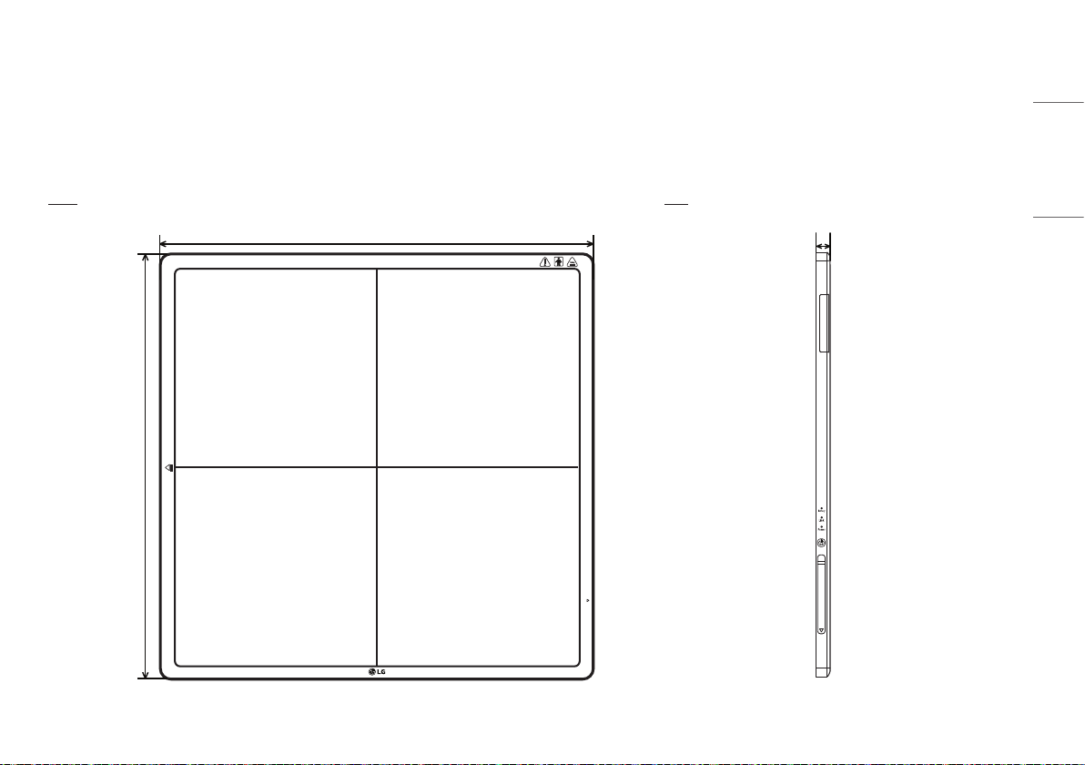
Control Box
Unit: mm (inch)
Front Side
Power Ethernet Ready Exposure
125.0 (4.9)
Power Ethernet Ready Exposure
255 (10.0)
109.8 (4.3)
19
ENGLISH
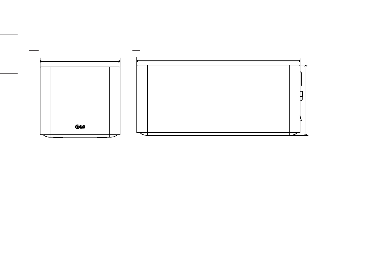
Battery
Unit: mm (inch)
Front Side
204.6 (8.0)
110.5 (4.3)
7.8 (0.3)
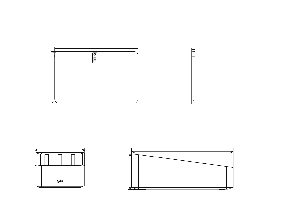
Battery Charger
Unit: mm (inch)
Front Side
125.0 (4.9)
90.0 (3.5)
255.0 (10.0)
20
ENGLISH
ENVIRONMENTAL REQUIREMENT
PC System requirement
PC Specification
CPU Intel i5
Memory 4 GB
Disk capacity At least 10 GB ~ 500 GB recommended
Network card Dual Ethernet 100/1000 Mbps
OS Windows 7/8.1/10 (32bit, 64bit)
Monitor Min. Resolution 1280 x 720
AP Cisco models recommended (e.g. Linksys EA9200)
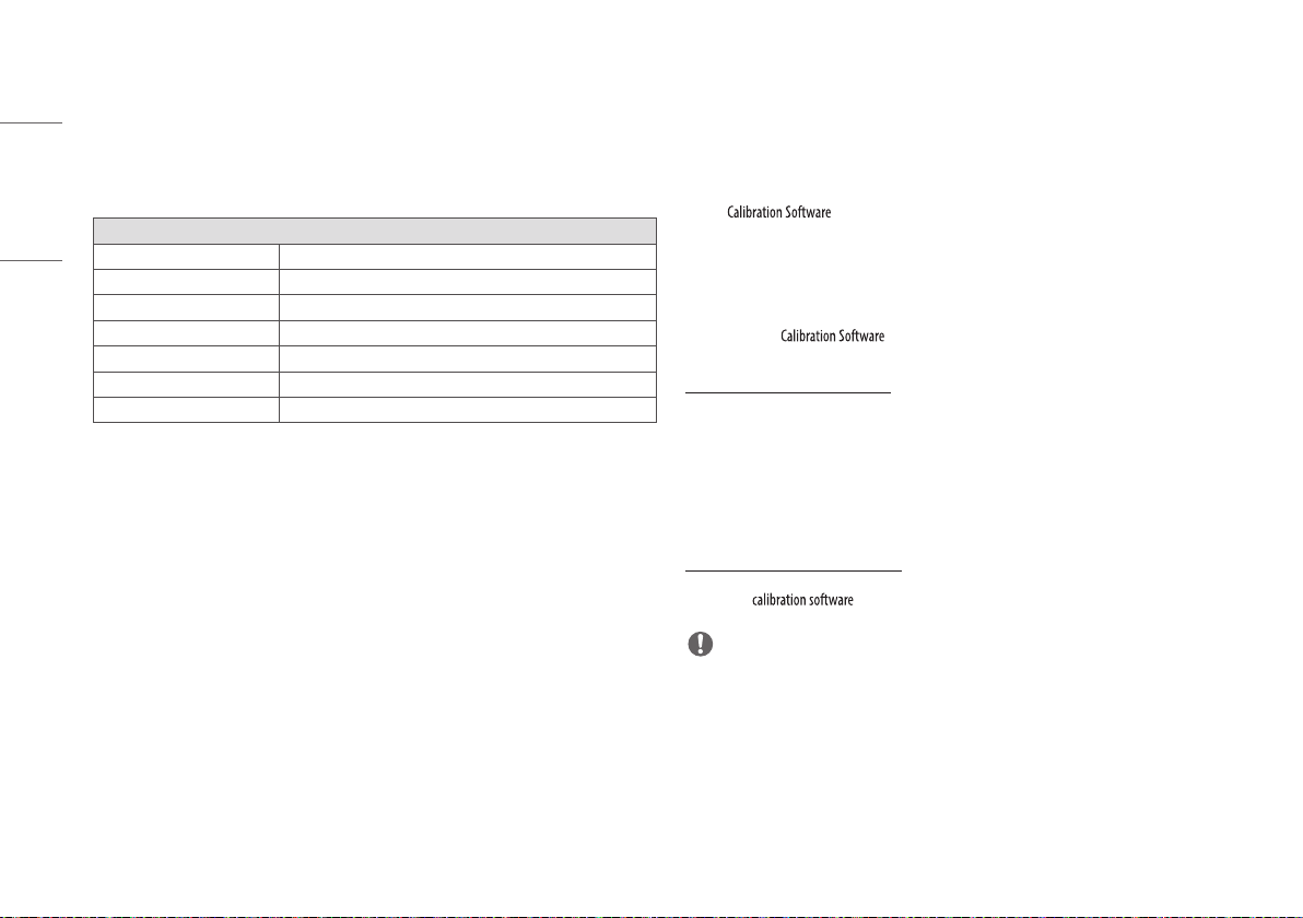
CALIBRATION SOFTWARE INSTALL
How to install
Run the installation file. Once the installation file has been executed, follow the
installation instructions on the screen.
How to delete
You can delete the in the following ways:
Deleting from the Control Panel
1 Select Control Panel from the Start menu.
2 Select Programs and Features in Control Panel.
3 Select the [LG DXD Calibration] on the lists.
4 When the program installation and deletion screen appears on the screen, select the [Delete] button.
5 Follow the deletion instructions on the screen and click the [Next] button to proceed.
Deleting with the installation file
1 Run the installation file, then follow the deletion instructions on the screen.
NOTE
• When using the installation file to delete the program, the installation file must be the same version as the
current software.
21
ENGLISH
CONNECTION TYPES
Connection of X-ray Generator - Detector
Select Trigger Mode in accordance with the acquisition method.
- Auto Mode: Detector detects the image obtained after the X-ray.
- Manual Mode: Detector acquires image by pressing Generator exposure switch.
Connection of Detector - PC
The connection mode used between the Detector and PC.
- Wired Mode: The wired connection between the Detector and a PC through the Control Box.
- Wireless mode: The wireless connection between the Detector and a PC through a wireless AP.
Network Connection Mode
When the Detector is booted, either the wired mode or wireless mode is automatically set depending on
whether or not the Main Cable is connected.
1 Power on after connecting the Main Cable: wired mode.
2 Power on after removing the Main Cable: wireless mode.
3 Removing the cable in the wired mode: switch to the wireless mode.
4 Connecting the cable in the wireless mode: maintain the wireless mode (charging).
Mode Generator - Detector Detector - PC
Case 1 Auto Mode Wired Mode
Case 2 Auto Mode Wireless Mode
Case 3 Manual Mode Wired Mode
Case 4 Manual Mode Wireless Mode
22
ENGLISH
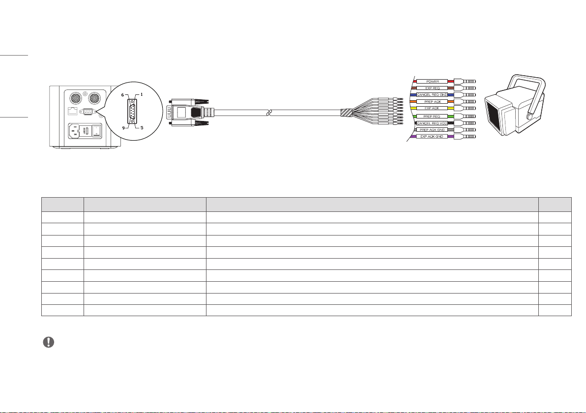
Trigger Cable
• Trigger Cable is connected between control box and X-ray Generator, and used only for manual mode, not auto mode.
AC-IN T4L 250V
Ethernet Sync
DXD 1 DXD 2
Labeling of pins X-ray Generator
NC: No Connection
No. Labeling of pins color Description
1 Red Power: X-ray Generator Supply Voltage (DC 12V ~24V) Use
2 Brown Expose signal from Generator to Control Box Use
3 Blue Cancel REQ Ground NC
4 Orange Prepare Acknowledge signal from Control Box to Generator Use
5 Yellow Expose Acknowledge signal from Control Box to Generator Use
6 Green Prepare signal from Generator to Control Box Use
7 Black Cancel request VCC NC
8 Gray Prepare Acknowledge Ground NC
9 Violet Ground of Signals Use
NOTE
• Connection of trigger cable and X-ray generator is to be performed by qualified personnel. The description of each pin is in the common language for this industry.
23
ENGLISH
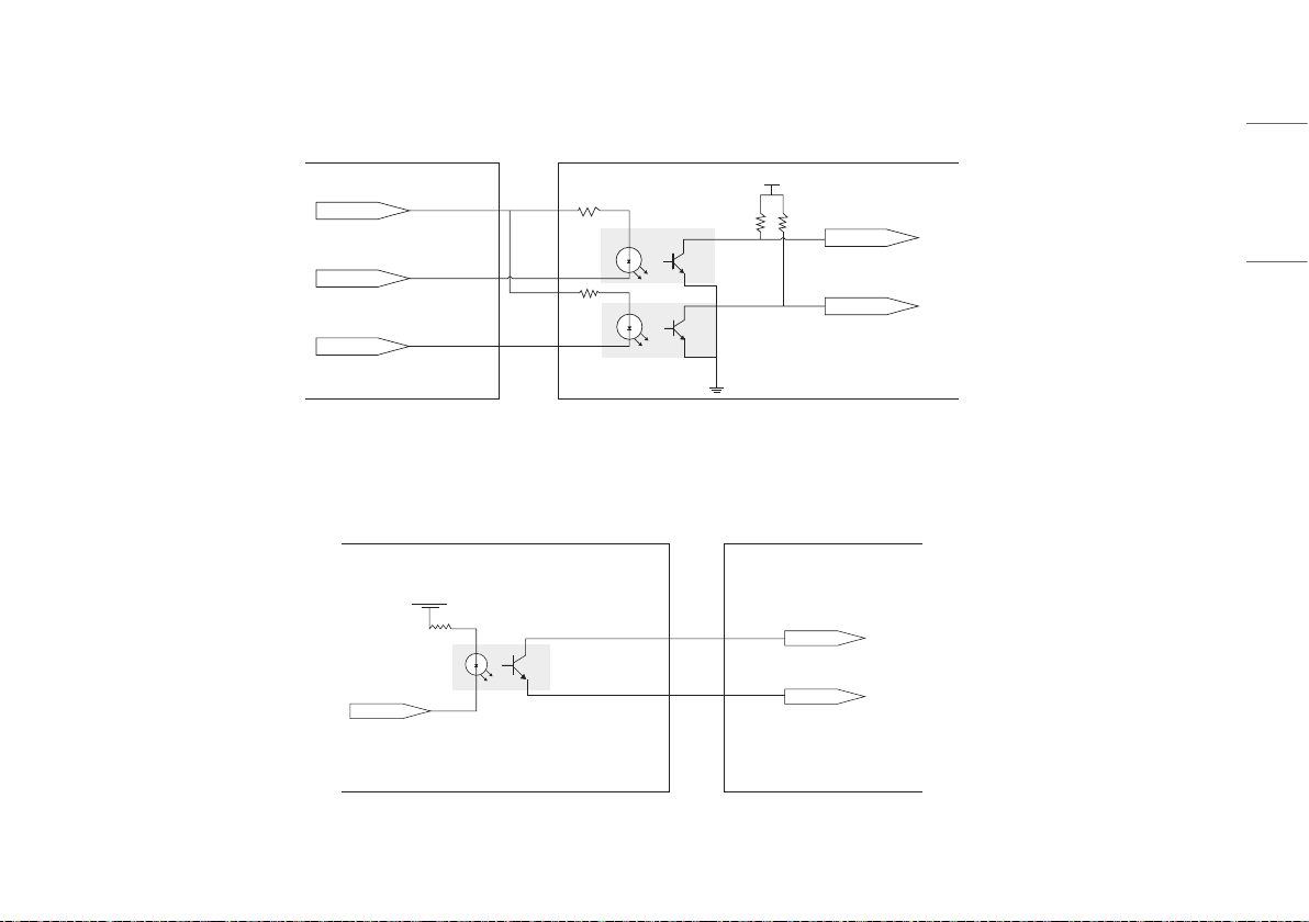
Block diagram of Trigger Cable connection
DC 12-24 V
PREPARE
VCC
EXPOSE
PREP_REQ
EXP_REQ
X-ray Generator Control Box
<Connection of X-ray Generator - Control Box>
VCC
EXPOSE
EXP_ACK
EXP_ACK_COM
Control Box X-ray Generator
<Assembly drawing>
24
ENGLISH
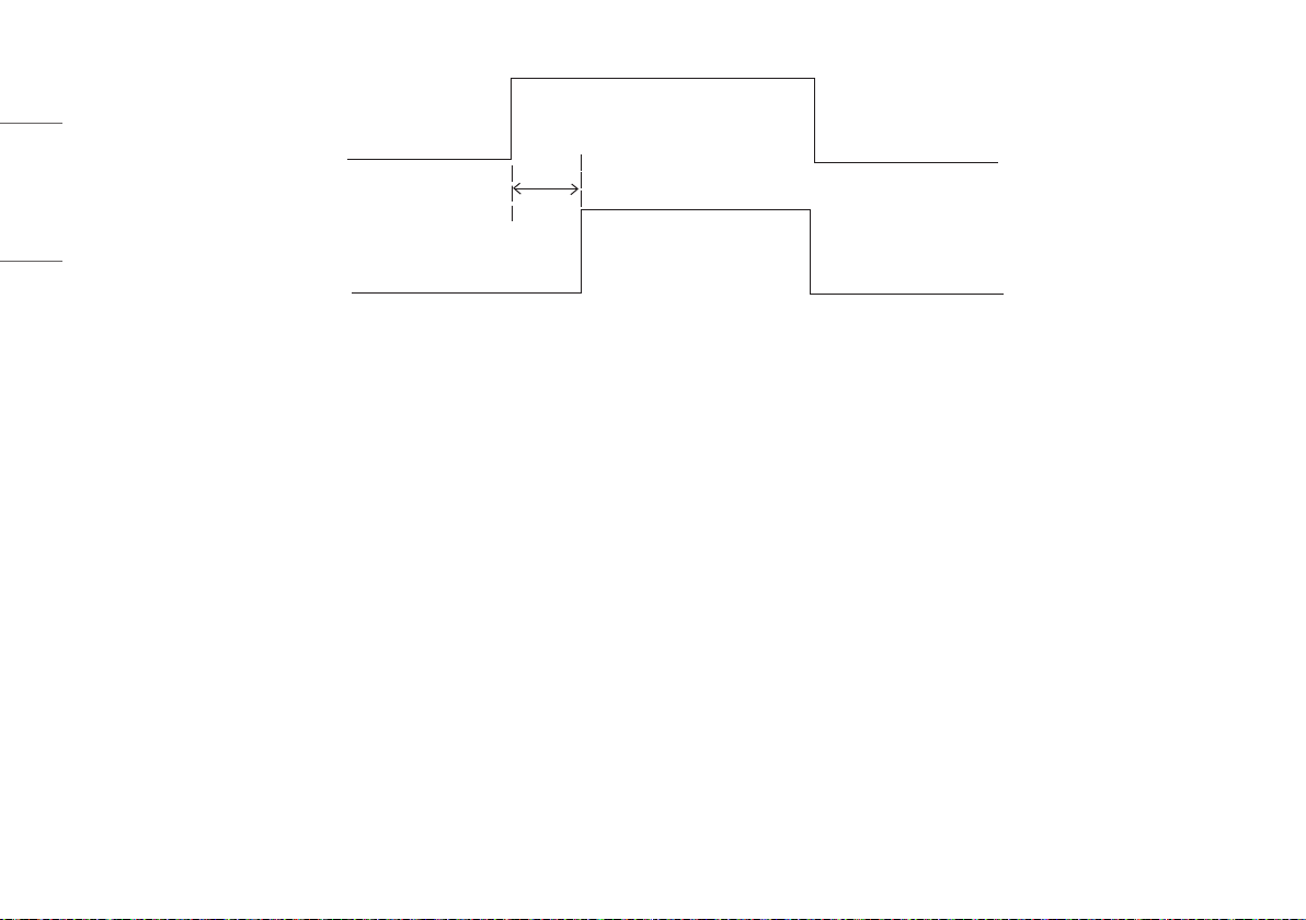
EXP_REQ
EXP_ACK
<Timing Chart>
25
ENGLISH
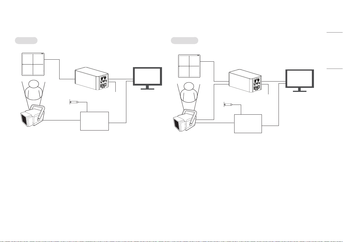
Detector and PC (Wired mode)
Auto Mode Manual Mode
100kg
Detector
Main Cable
Control Box
LAN cable
X-ray Generator
Interface
X-ray
Generator
X-ray Switch
Object
PC
Power Cord
(AC 100-240 V~)
100kg
Detector
Main Cable
Control Box
LAN cable
X-ray Generator
Interface
X-ray
Generator
X-ray Switch
Object
Trigger
cable
PC
Power Cord
(AC 100-240 V~)
26
ENGLISH
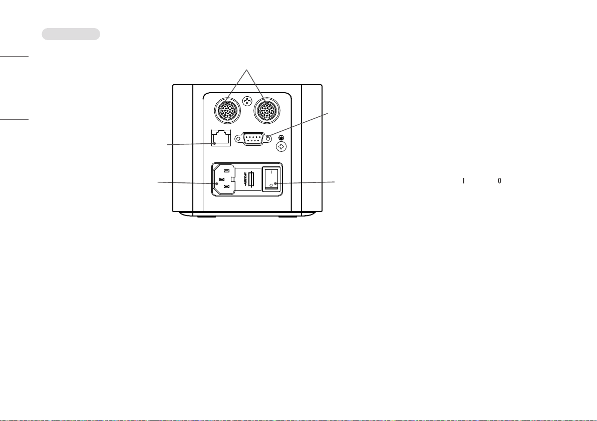
Connecting cable
Main Cable: Connects between Control Box and Detector.
2 Detectors can be connected, in case of 1 Detector, connection of any port is acceptable.
LAN Cable: Connects between Control Box and PC.
AC power cord connection.
Trigger Cable: Connects between control box and Generator. In case of auto
mode, this connection is not necessary.
AC Switch: This switch is for AC On/Off switching. Mark
: AC On / Mark : AC Off
AC-IN T4L 250V
Ethernet Sync
DXD 1 DXD 2
Power Ethernet Ready Exposure
27
ENGLISH
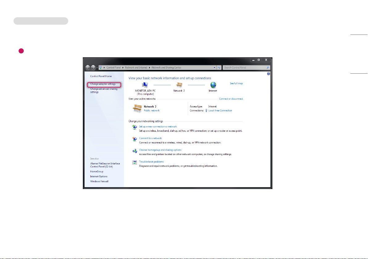
Connect - Wired Connection
1 Use the LAN cable to connect a PC to the Control Box and connect the Detector to the Control Box with the Main Cable.
2 Follow the steps below to set up the PC.
1
Launch the [Network and Sharing Center] and click [Change adapter settings].
28
ENGLISH
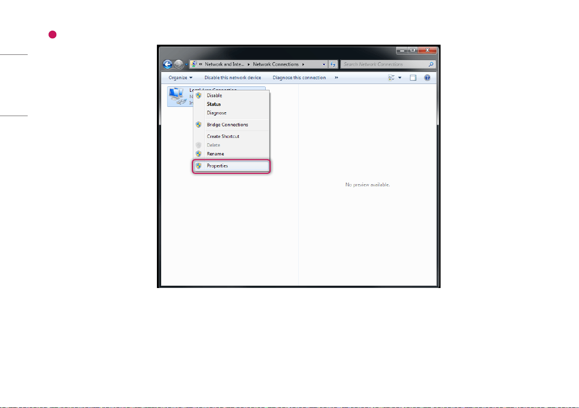
2
Right-click Local Area Connection, and click [Properties].
29
ENGLISH
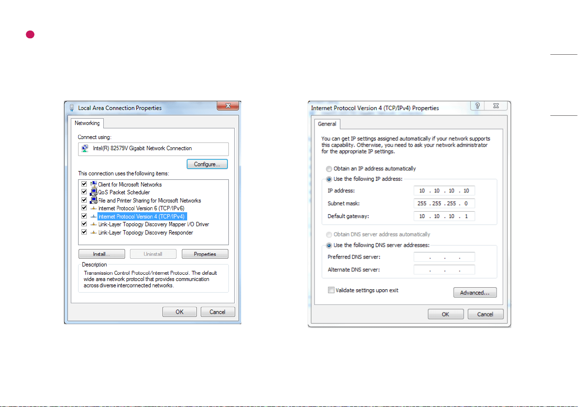
3
Select [Internet Protocol Version 4 (TCP/IPv4)], and then click [Properties] to set the IP address as follows:
- IP address: Input anyone from 10.10.10.2 to 10.10.10.254
However, IP 10.10.10.100 is not allowed, because Detector IP is set to 10.10.10.100 in factory.
- [Subnet Mask]: 255.255.255.0.
- [Default Gateway]: 10.10.10.1.
- DNS setting is not needed.
30
ENGLISH
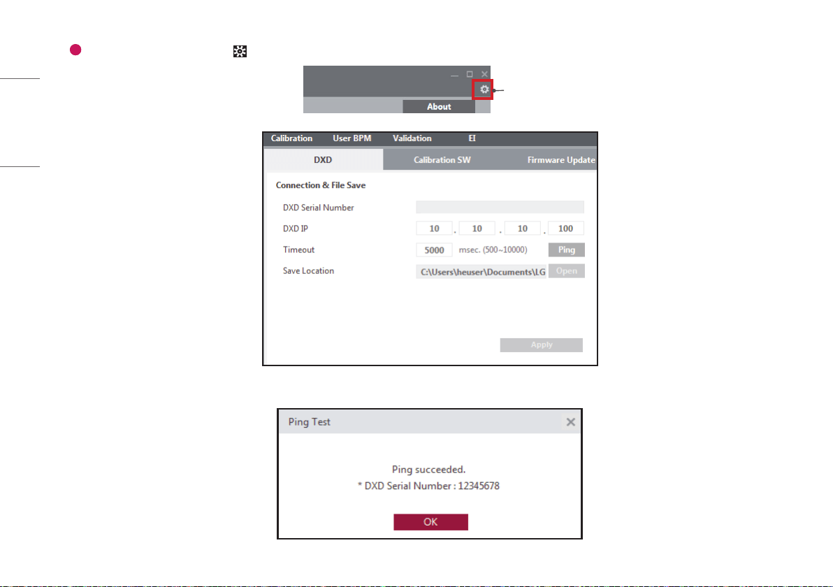
4
Run the LG DXD Calibration program. Go to > [DXD] > [Connection & File Save], enter DXD IP (10.10.10.100), then run the [Ping] to check the connection.
Setting
If following screen is pop-up after [Ping] click, connection is successful, everything for system operation is ready.
31
ENGLISH
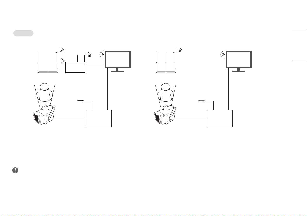
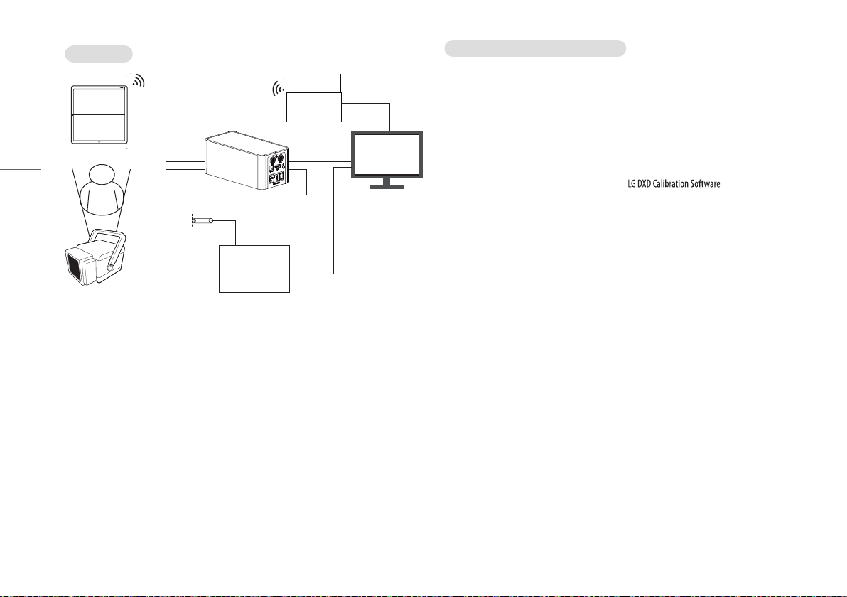
Detector and PC (Wireless mode)
Auto Mode
1. Station mode (for the use of external AP) 2. AP mode (for the use of detector internal AP)
100kg
Detector
AP
LAN cable
X-ray Generator
Interface
X-ray
Generator
X-ray Switch
Object
PC
100kg
Detector
X-ray Generator
Interface
X-ray
Generator
X-ray Switch
Object
PC
NOTE
• Please install the AP and Detector as near as possible without obstacles in between them.
32
ENGLISH
Manual Mode
100kg
Detector
Main Cable
Control Box
LAN cable
LAN cable
X-ray Generator
Interface
X-ray Switch
Object
Trigger
cable
PC
Power Cord
(AC 100-240 V~)
X-ray
Generator
AP
Making connections-Wireless connection
1 The Default Wireless Settings as below.
• Station mode (connection via external AP)
- SSID: LGEDXD
- Password: @lgedxd2000
• AP mode (connection via detector AP)
- SSID: LGEDXD_SOFTAP
- Password: @lgedxd2000
2 It is possible to change the Wireless Settings using .
- Please see " Wireless AP configuration" for details.
3 Please reboot the Detector after removing the Main Cable on Detector. (When the power is turned on after
removing the main cable: The device switches to wireless mode. The device initially starts in station mode.
If the user changes to station mode or AP mode, the device operates in the changed mode. )
4 The wireless mode changes when the power button is pressed for about 1 second after rebooting with the
main cable removed.
33
ENGLISH
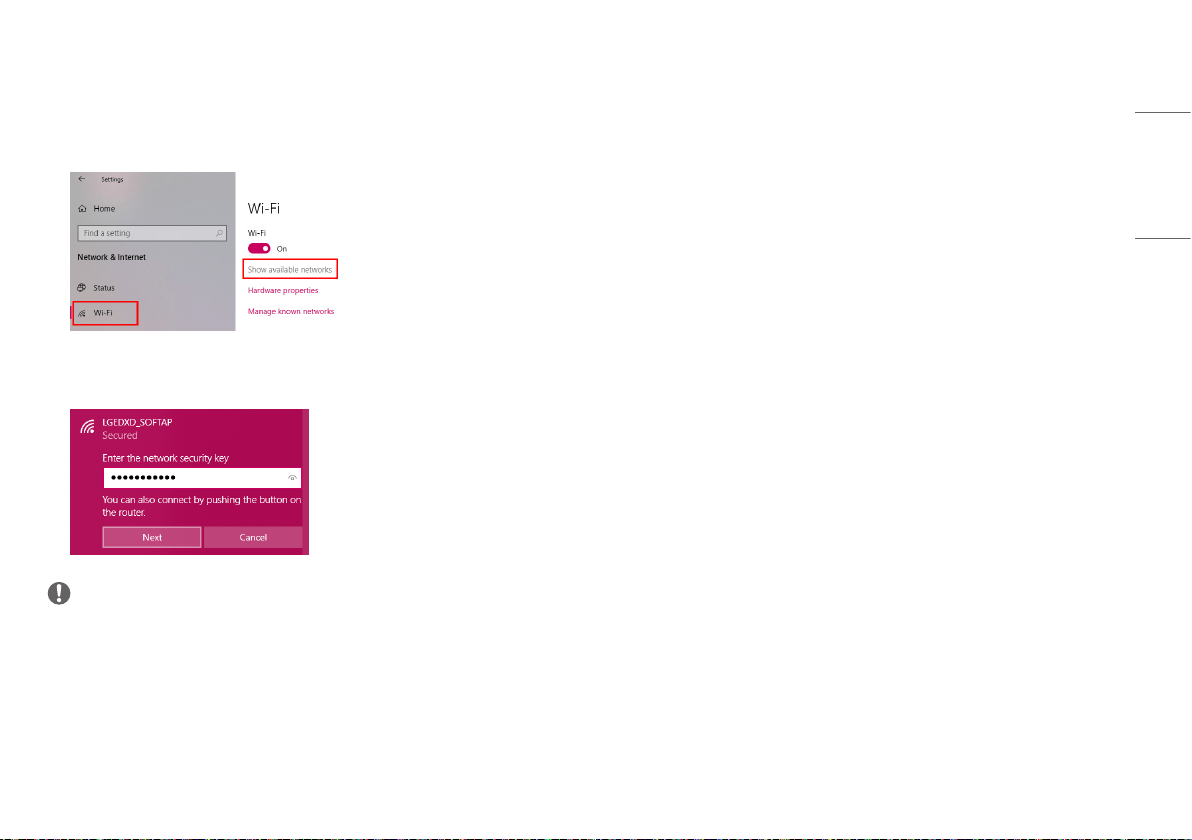
5 The Connection method as below.
• Station mode
- PC settings and connection with Detector are same with wired Connection.
• AP mode
- Enter [Wi-Fi] under PC Settings, and enter [Show available networks].
- Attempts are made to connect after checking the DXD wireless AP SSID, which is shown as the research
result (the initial value is LGEDXD_SOFTAP). Enter the password (the initial password is @lgedxd2000) to
connect.
NOTE
• Tip: Refer to Wireless AP Set Up Guide
- Supplement. Wireless Access Point Setup Guide (Model: Cisco Linksys EA9200)


2
ENGLISH
CONTENTS
CALIBRATION SOFTWARE ........................................ 3
OPERATION ......................................................... 14
SERVICE MANUAL ................................................ 41
MAINTENANCE .................................................... 51
TROUBLESHOOTING ............................................. 52
PROGRAM NOT LAUNCHED DUE TO ACCESS
PRIVILEGE ISSUES ................................................ 54
TROUBLESHOOTING FIREWALL ISSUES ................... 55
WIRELESS ........................................................... 58

3
ENGLISH
CALIBRATION SOFTWARE
When acquiring images from the detector, calibration is essential to obtain images of high quality. enables you to create and check the necessary values for the calibration.
NOTE
• It is recommended to perform a calibration once per month for the following three months after the purchase, and then once every six month to ensure the quality of images.
• It is also recommended to turn on the detector for 15 minutes before the Calibration.
• The default values set in can be changed depending on the actual conditions of use.
Security
cannot be used independently without being connected to the detector. The software cannot perform all actions, including moving to another menu and confirming settings, without the actual
connection. In addition, even if the software is connected to the detector, cannot be performed before the initial date of the product installation is registered.
The features of the include (Settings), [Calibration], [User BPM], [Validation] and [EI].
4
ENGLISH
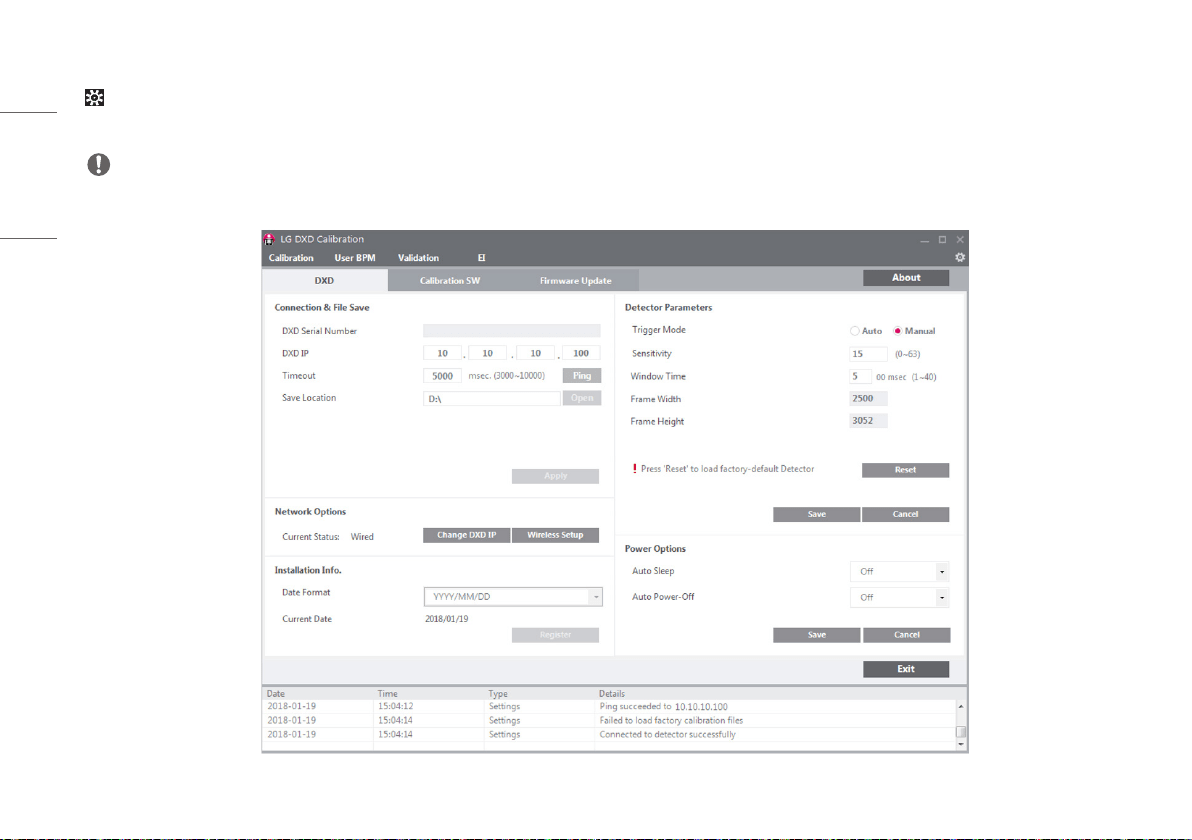
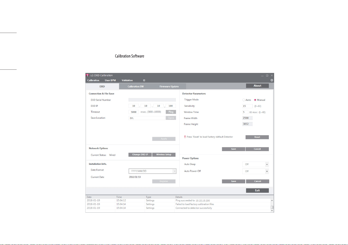
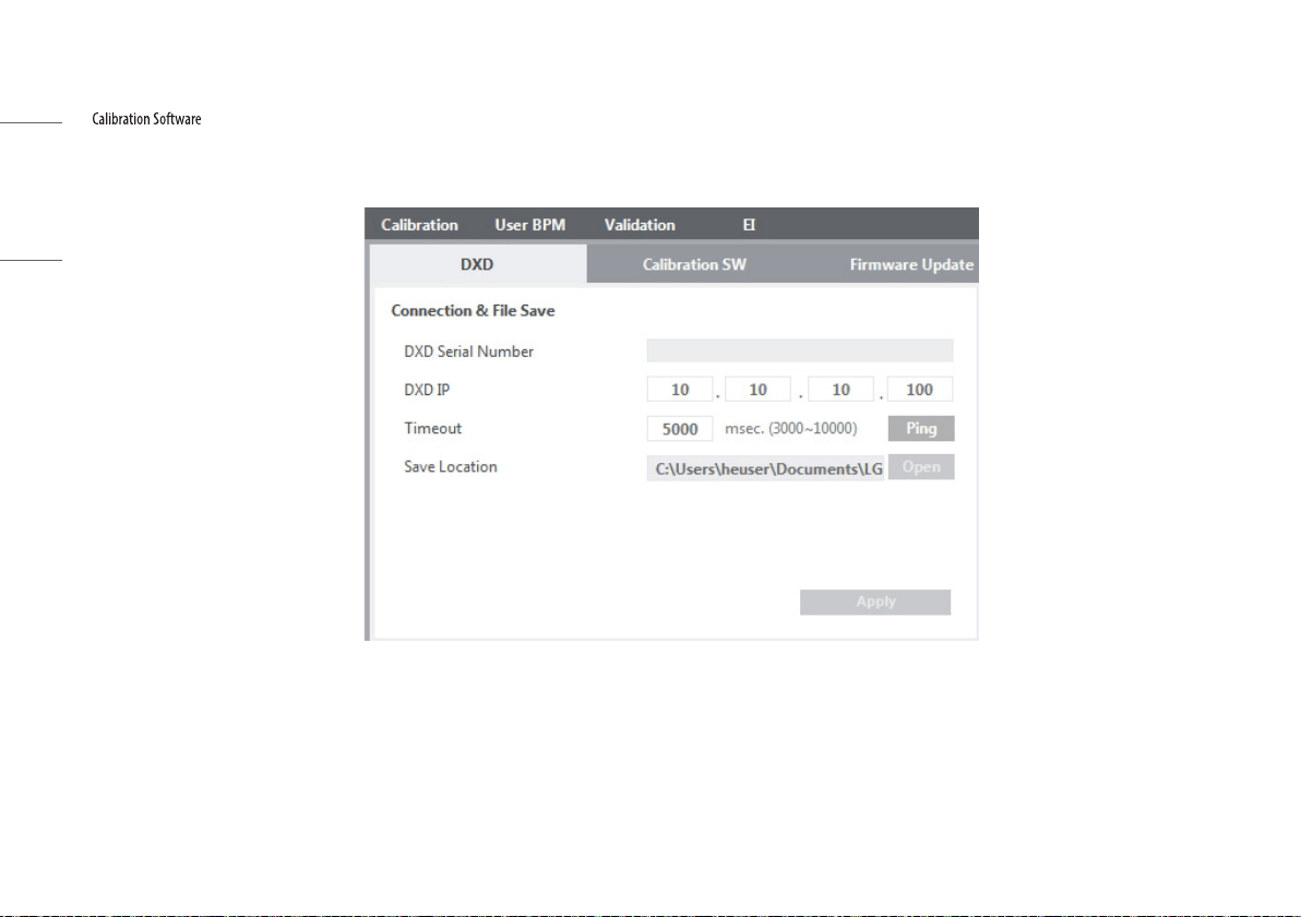
Settings
include [DXD] settings, [Calibration SW] settings and [Firmware Update].
• [DXD]: Configures the settings required to obtain calibration images and detector settings.
NOTE
• Detailed explanations of each icon is explained on the back page.
5
ENGLISH
• [Calibration SW]: Configures the settings required for to algorithms.
NOTE
• Detailed explanations of each icon is explained on the back page.
6
ENGLISH
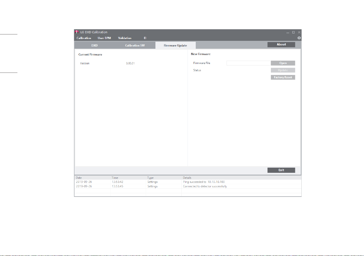
• [Firmware Update]: Checks the firmware version of the detector or performs the firmware update. You can update firmware by this menu.
7
ENGLISH
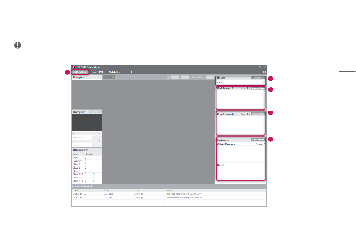
Calibration
[Calibration] involves the following procedures.
• Dark Image and Bright Image are obtained from the detector.
- [Dark Image(s)]: An image obtained without generating X-rays.
- [Bright Image(s)]: An image obtained by generating X-rays without a phantom or any other object on the detector.
• Generate [Avgdark.raw], [Offset.raw], [Gain.raw], [BPM.raw]: Used for Corrected Image calculations.
- Corrected Image: An image generated by applying calibration results to a raw image.
• Creates a Bad Pixel Map. Uses the surrounding pixel values to calibrate the bad pixel values.
NOTE
• This page has a brief explanation, a detailed one can be found at the end of this document.
8
ENGLISH
User BPM
Enables users to manually make changes in the [Bad Pixel Map] (BPM.raw) created from [Calibration].
NOTE
• This page has a brief explanation, a detailed one can be found at the end of this document.

9
ENGLISH
Validation
This is used to validate the final image by applying [Calibration] results to the image.
NOTE
• This page has a brief explanation, a detailed one can be found at the end of this document.
10
ENGLISH
EI (Exposure Index)
This calculates and saves median output value per input dose as a linear expression and a table.
NOTE
• This page has a brief explanation, a detailed one can be found at the end of this document.
11
ENGLISH
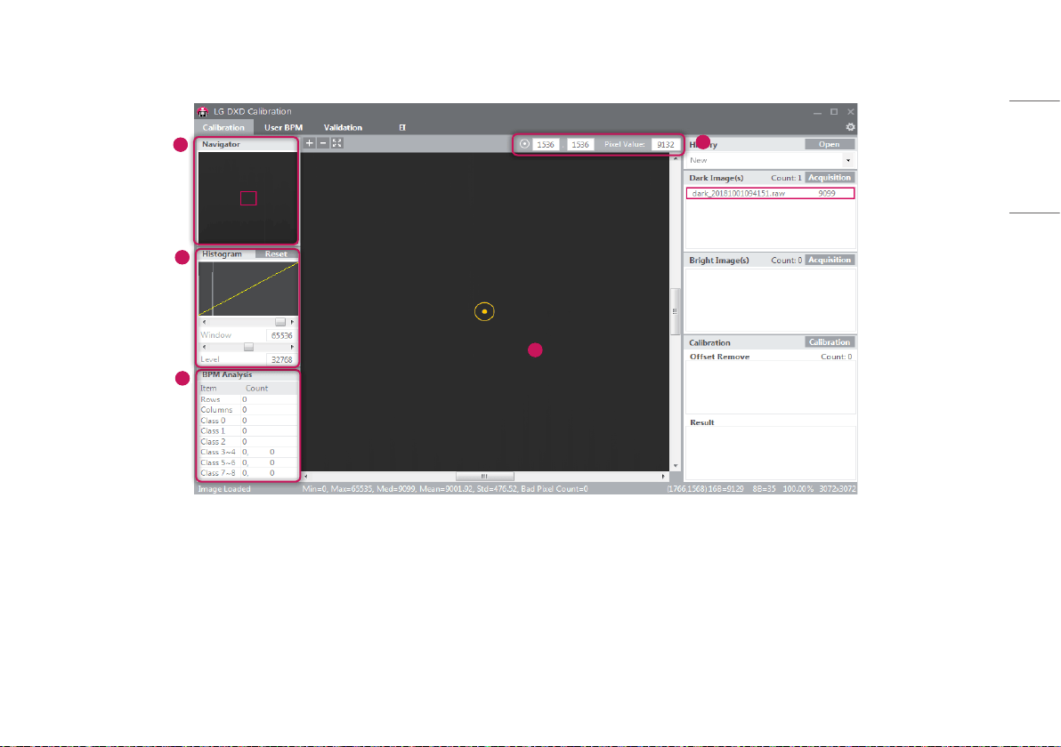
Image Functions
5
3
2
4
1

12
ENGLISH
1
Image Viewer
• [Calibration], [User BPM], [Validation] and [EI] menu have an image viewer to show the images
acquired.
• When creating or clicking an image, the image is loaded and shown in the viewer.
• Information about the image will be shown in the areas below.
- [Image Loaded]: displays whether the image is loaded in the image area or not.
* When the image is loaded: [Image Loaded]
* When the image is not loaded: [Image not Loaded]
- [Min]: The minimum pixel value in the image area.
- [Max]: The maximum pixel value in the image area.
- [Med]: The median value of the image.
- [Mean]: The mean value of the image.
- [Std]: The standard deviation of the image.
- [Bad Pixel Count]: The number of Bad Pixels.
- = N, = M: Representation of pixel values in (x, y) in bits.
- %: The rate of the image displayed in the image area against the entire image.
- (W x H): The size of the entire image.
2
[Navigator]
• [Navigator] shows the entire area of the image acquired and also indicates the enlarged or reduced
area.
• [Navigator] has a red box that indicates the area shown in the image viewer.
• [Navigator] moves the red box to wherever you click, and the selected area appears in the image viewer.
3
[Histogram]
• Shows the [Histogram] of the image acquired.
• [Window] / [Level] are used to adjust Histogram to help reading the image.
• [Histogram] controls [Window] / [Level] with the <> buttons and the scroll bar under the Histogram
graph.
• When the [Reset] button is clicked, it resets to the default values.
4
Reference Point
• A reference point can be set by clicking on any location in the image viewer, and the coordinates and
pixel values for the reference point will be shown on the top. You can also move the reference point by
manually entering the x and y values.
- Only numbers can be entered for a reference point.
5
[BPM Analysis]
• Shows the result of the analysis of the Bad Line and Bad Pixel Class based on the [Bad Pixel Map] after
the Calibration.
13
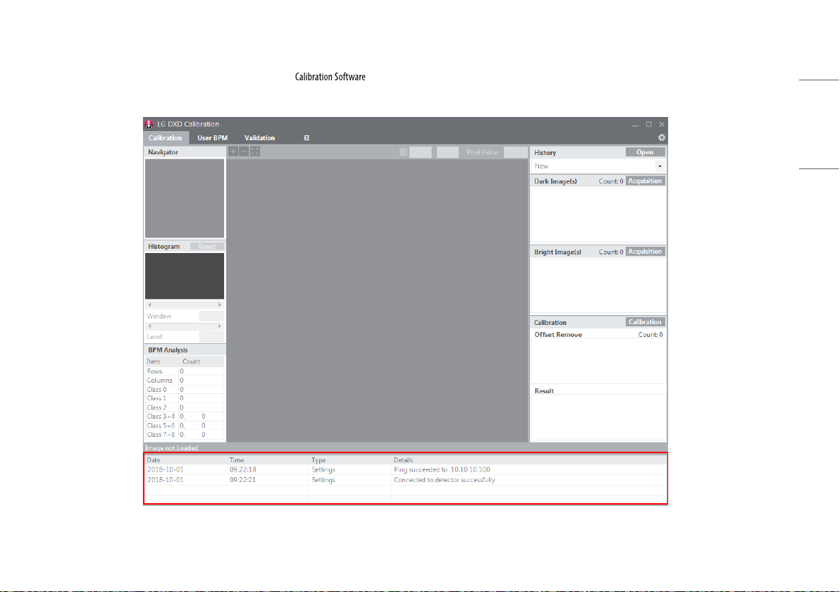
ENGLISH
Log
Shows necessary information for users to understand the process to perform .
Consists of [Date], [Time], [Type] and [Details], and the data will be saved in a log file.
14
ENGLISH
OPERATION
Launching Program
• Double-click the executable file installed on the PC to launch .
• When launching it for the first time, you will be directed to the Settings screen.
15
ENGLISH
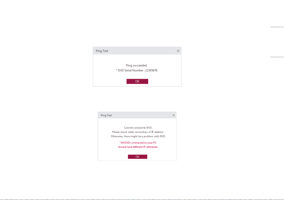
IP Address Check and Ping Test
• The detector has a default IP address.
• If the IP address of the detector is changed, a new IP address must be entered in the detector IP in the Calibration tool.
• After completing the IP Address and [Timeout] settings, click the [Ping] button to run a [Ping Test]. A pop-up message appears when the [Ping Test] is successful.
• If the [Ping Test] fails, a pop-up appears as shown below. If this pop-up appears, check your PC network settings, detector-to-PC connection, status of the detector, status of the Control Box, and IP address, and run
the [Ping Test] again.
16
ENGLISH
Save Location Check
stores images acquired, logs, result files, and factory Calibration results in the specified location.
This location can be changed from [Save Location].
Click the [Apply] button to create a folder in the specified location.

17
ENGLISH
Apply
After completing the [Ping Test] and [Save Location] check, click the [Apply] button to perform the following tasks.
1 Automatically create necessary folders under the specified folder in the [Save Location].
2 Load and save the factory Calibration results from the detector.
3 Load the detector settings.
Custom folder Auto-create a serial number folder
(Created when completing Apply)
Condition: create a folder when there is no folder with the
same serial number in the specified folder
Creating a date-time folder
(Created when the [Calibration] button is clicked)
[Avgdark.raw]
[Gain.raw]
[Offset.raw]
[BPM.raw]
EI result
(the applied date-time folder is created when an EI is
performed)
History file
Log Log file (connection logs, etc.)
Image Bright image
Dark image
User BPM image
Validation image
EI image
Raw image
Factory Calibration
(Created when there is no folder or file upon the completion
of Apply or if the file is abnormally small in size)
[Avgdark.raw]
[Gain.raw]
[Offset.raw]
[BPM.raw]
18
ENGLISH
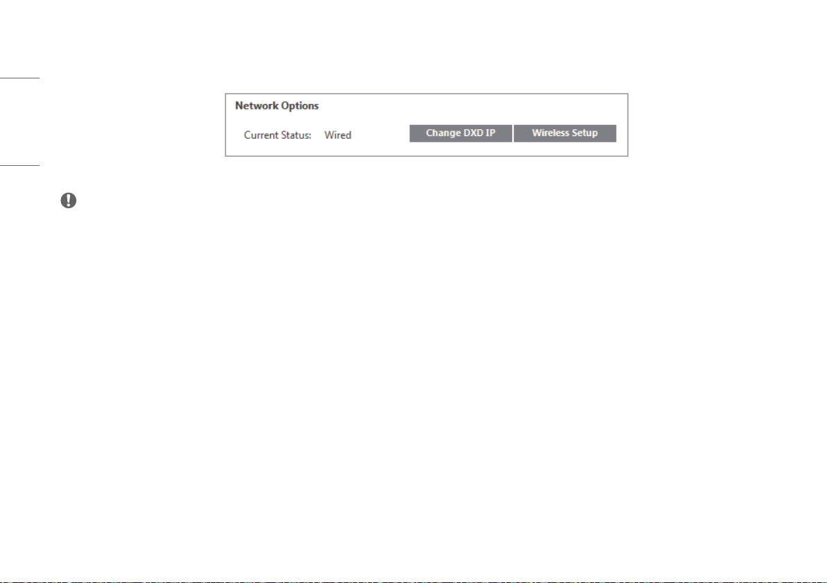
4 Display the network status of the detector once the Apply process is completed.
[Current Status]: [Wired] connection. / [Wireless] connection. (Available only with a wireless model)
NOTE
• You must complete the Apply process before moving to another menu. ([Calibration], [User BPM], [Validation], and [EI])
19
ENGLISH
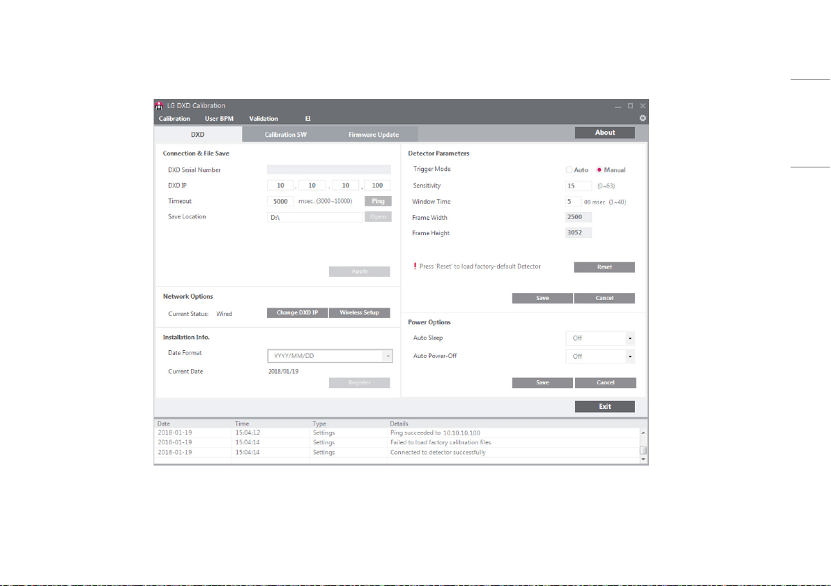
Checking and Changing Detector Settings
During the Apply process, the current settings of the detector will be loaded on the setting screen as shown below.

20
ENGLISH
• [Detector Parameters]: Settings used when acquiring an image from the detector.
• Click the [Save] button to apply the settings entered.
• Details of the settings are as follows:
- [Trigger Mode]: Set the [Trigger Mode].
* [Auto]: Enable the Auto Exposure Detection feature.
* [Manual]: Disable the Auto Exposure Detection feature.
- [Sensitivity]: Sensitivity of the panel.
- [Window Time]: Set the time to read the data after the X-ray exposure. (Unit: 100 ms, when you enter
5, the time is set to 500 ms)
- [Frame Width] / [Frame Height]: Number of pixels in the detector.
• The operations of each button are as follows:
- [Save]: Apply the changed settings.
- [Reset]: Load the factory settings.
- [Cancel]: Load the last saved settings.
21
ENGLISH
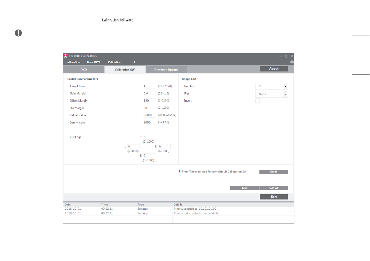
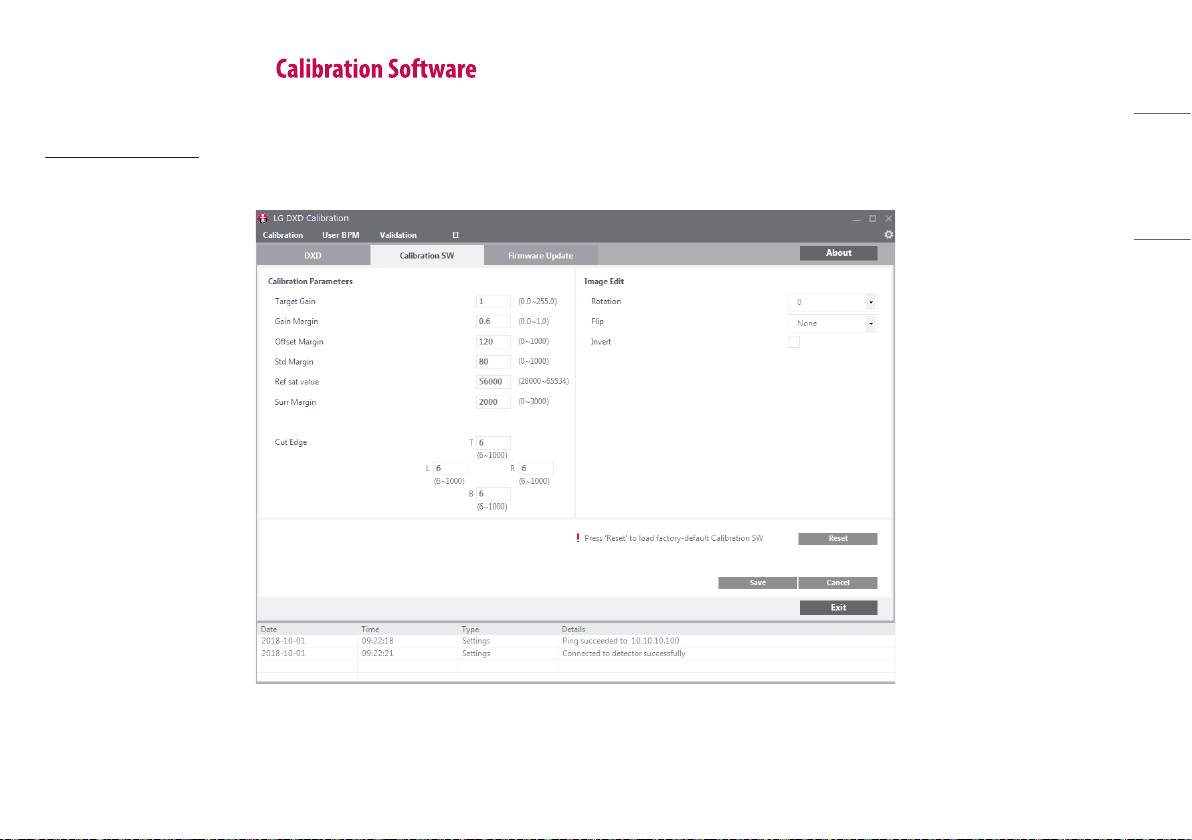
Checking and Changing Settings
Click the [Calibration SW] tab to update [Calibration Parameters].
[Calibration Parameters]
These parameters are the settings used in the Calibration process. These settings can be adjusted according to the actual operating environment.
22
ENGLISH
• Details of the settings are as follows:
- [Target Gain]: Gain in the algorithm.
- [Gain Margin]: Set as a Bad Pixel if it exceeds the [Gain Margin].
- [Offset Margin]: Set as a Bad Pixel if it exceeds the [Offset Margin].
- [Std Margin]: Set as a Bad Pixel if it exceeds the [Std Margin].
- [Ref sat value]: The maximum pixel value that can be displayed.
- [Surr Margin]: Set as a Bad Pixel if the difference between the reference pixel value and the
surrounding pixel value is greater than the [Surr Margin] in the corrected Bright image.
- [Cut Edge]: Display the pixel values to cut off from the frame image (top/bottom/left/right). After
acquiring an image through [Validation] or [EI], display the image data shown in the
image viewer as a line.
[Image Edit]
These settings are used in the image viewer.
• [Rotation]: Set the rotation angle of the image. ([0˚], [90˚], [180˚], and [270˚])
• [Flip]: Set whether to rotate the image shown in the image viewer. ([None], [Horizontal], and [Vertical])
• [Invert]: Reverse the image data shown in the image viewer.
• Click the [Save] button to apply the settings entered.
• The operations of each button are as follows:
- [Save]: Apply the changed values.
- [Reset]: Load the factory values.
- [Cancel]: Load the last saved values.
- [Exit]: Returns to the last screen.
NOTE
• You must complete the Apply process before proceeding with the next step.
23
ENGLISH
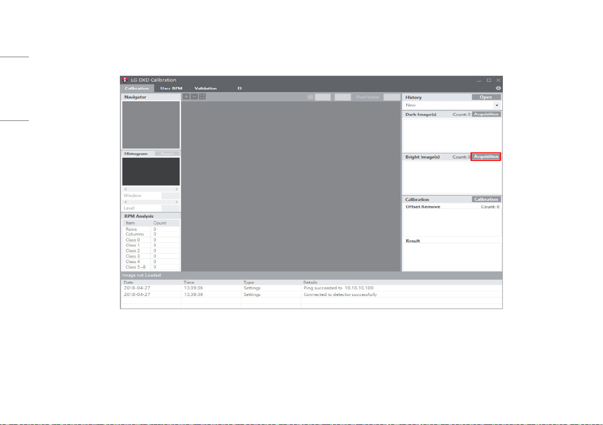
Calibration
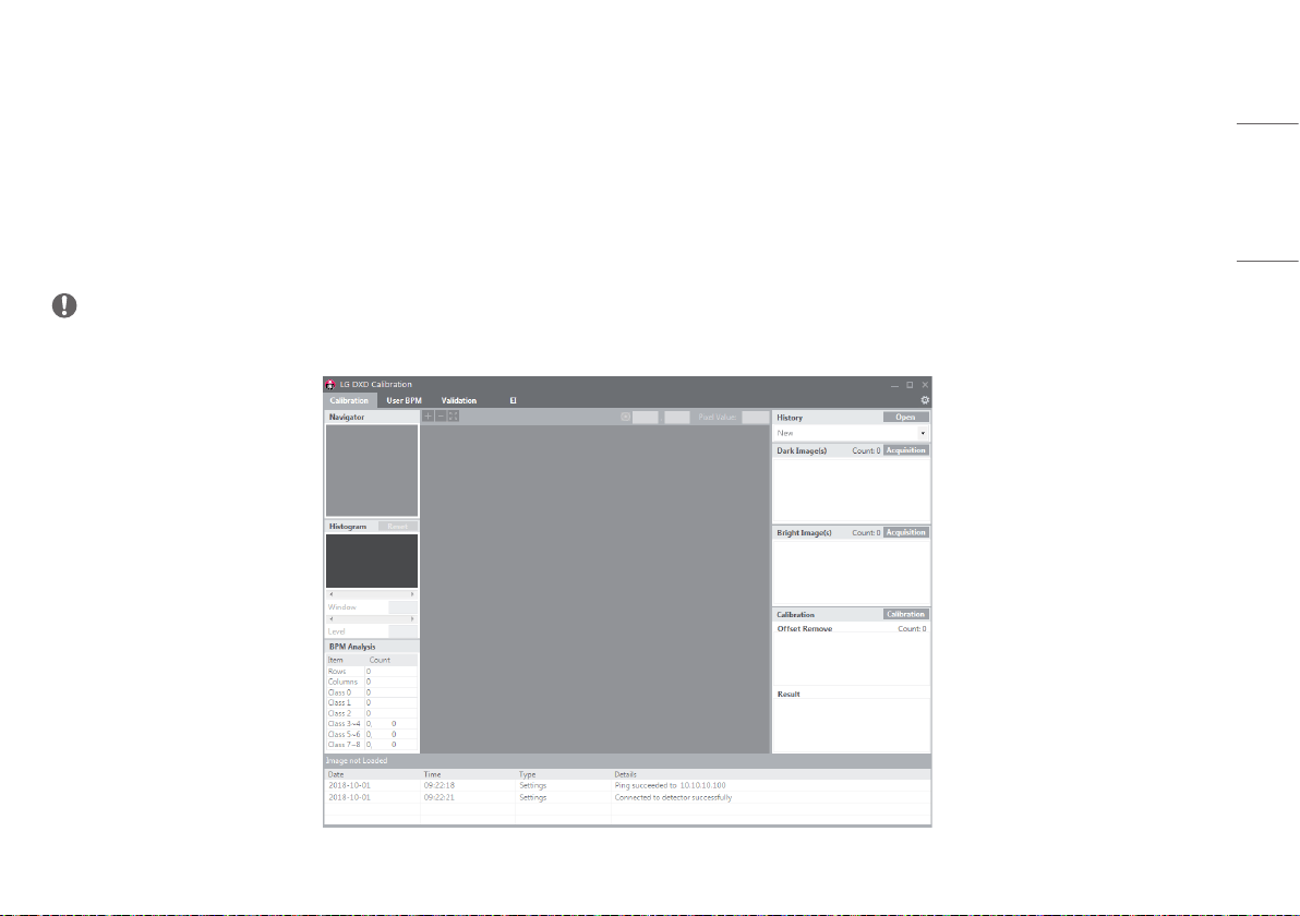
When all settings are completed, click the [Calibration] tab to go to the [Calibration] menu.
NOTE
• All settings must be complete before entering into the tab.
5
2
1
3
4
24
ENGLISH
1
Enter into the [Calibration] menu
• Click the [Calibration] menu to enter.
2
Acquire a Dark Image
• Acquire a Dark Image needed for the [Calibration].
- When Dark Image is acquired, images increase, and the file is saved in the image folder specified in
.
- The median value of the image is displayed next to the image file name.
- Compare multiple images and remove any faulty image by right-clicking the image.
- When deleting a file, the file list and saved file are also deleted.
3
Acquire a Bright Image
• Acquire a Bright Image needed for the [Calibration].
- When Bright Image is acquired, images increase, and the file is saved in the image folder specified
in .
- The median value of the image is displayed next to the image file name.
- Compare multiple images and remove any faulty image by right-clicking the image.
- When deleting a file, the file list and saved file are also deleted.
NOTE
• Up to 10 Dark Image and Bright Image each can be saved. When the number of images exceeds 10, the
oldest image will be deleted first.
• For a bright image, X-ray must be irradiated during image acquisition.
• Images are acquired automatically in Calibration Software Version 3.00.16 and higher. Four images
are acquired automatically among dark images and ten images among bright images. For Calibration
Software version 3.00.16 or lower, you must select the [Acquisition] button whenever acquiring an
image.
4
[Calibration]
• [Calibration] is performed in this menu.
- Dark Image: 4 images (minimum)
- Bright Image: 5 images (minimum), 10 images (maximum)
• When [Calibration] is performed, the standard pixel values of a bright image are as follows.
- For Calibration Software version 3.00.16 or lower
Bright images are acquired within the pixel range of 1500 – 15000. (Examples of acquisition points in
case of 10 images: 1500, 1700, 2200, 2500, 3300, 4000, 5000, 6500, 8500, 10500, 15000)
- For Calibration Software version 3.00.16 and higher
Bright images are acquired with a pixel value close to 6000 when the tube voltage is 60 kv - 70 kv.
(The acceptable range is -10 % - 20 % for a pixel range of 5400 - 7200. Images outside this range are
not included.)
• The result of the [Calibration] will be saved in a folder created based on the date and time of performing
[Calibration].
• When the [Calibration] is completed, [BPM Analysis] will be updated.
NOTE
• When running more than 5 [Calibration], the sixth [Calibration] is saved after the first [Calibration] is
automatically deleted.
• If you wish to make a backup, copy the folder containing the result and paste in another location.
25
ENGLISH
5
[History]
• You can load the result of the [Calibration] performed previously. Click the [Open] button to open the file.
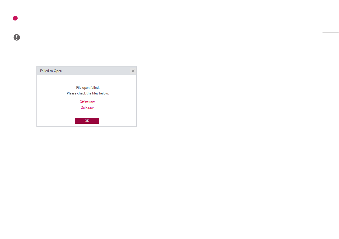
NOTE
• You only need to select one file to load all relevant files. (select one from [Avgdark.raw], [Offset.raw], [Gain.raw], and [BPM.raw] to load all four files)
• If an error occurs while loading the files, the following pop-up appears. When the following pop-up appears, check the file size, location, file name and access privilege to the folder and try again.
26
ENGLISH
How to acquire Bright image with X-Ray shot. This procedure is also applied for pediatric patient.
X-ray Generator connection is explained in this manual.
1 Click the [Acquisition] button next to [Bright Image(s)] text.
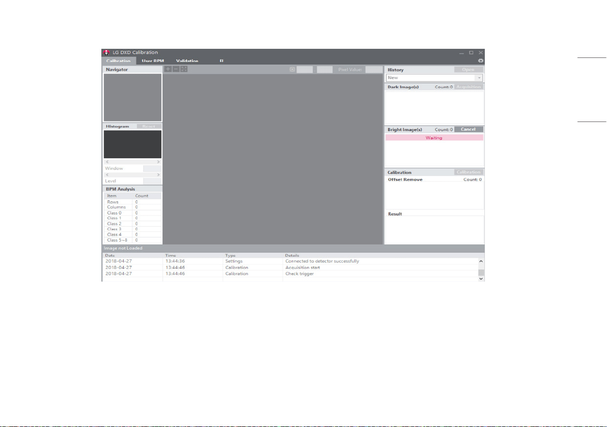
27
ENGLISH
2 To implement X-ray shot. Calibration SW will wait for a X-Ray acknowledgement signal from DXD and it will display a waiting sign.
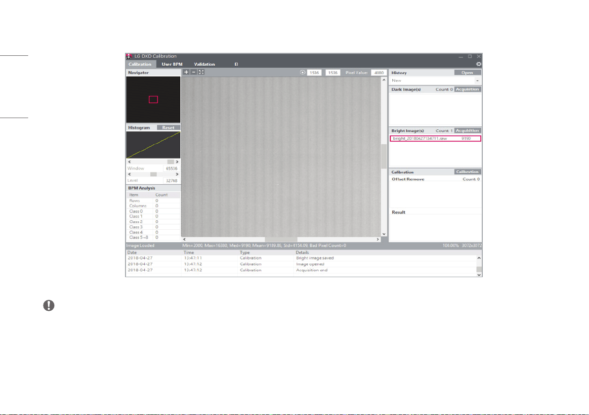
28
ENGLISH
3 Acquired bright image is displayed in list view, please check its name and median value. Actual file is saved Image folder in the workspace.
NOTE
• These acquisition steps are all same to [User BPM], [Validation] and EI Image acquisition.
• [Calibration SW] support Window level adjustment, but does not support other image post-processing function.
• The process of obtaining the image for paediatric patients is same with other patients.
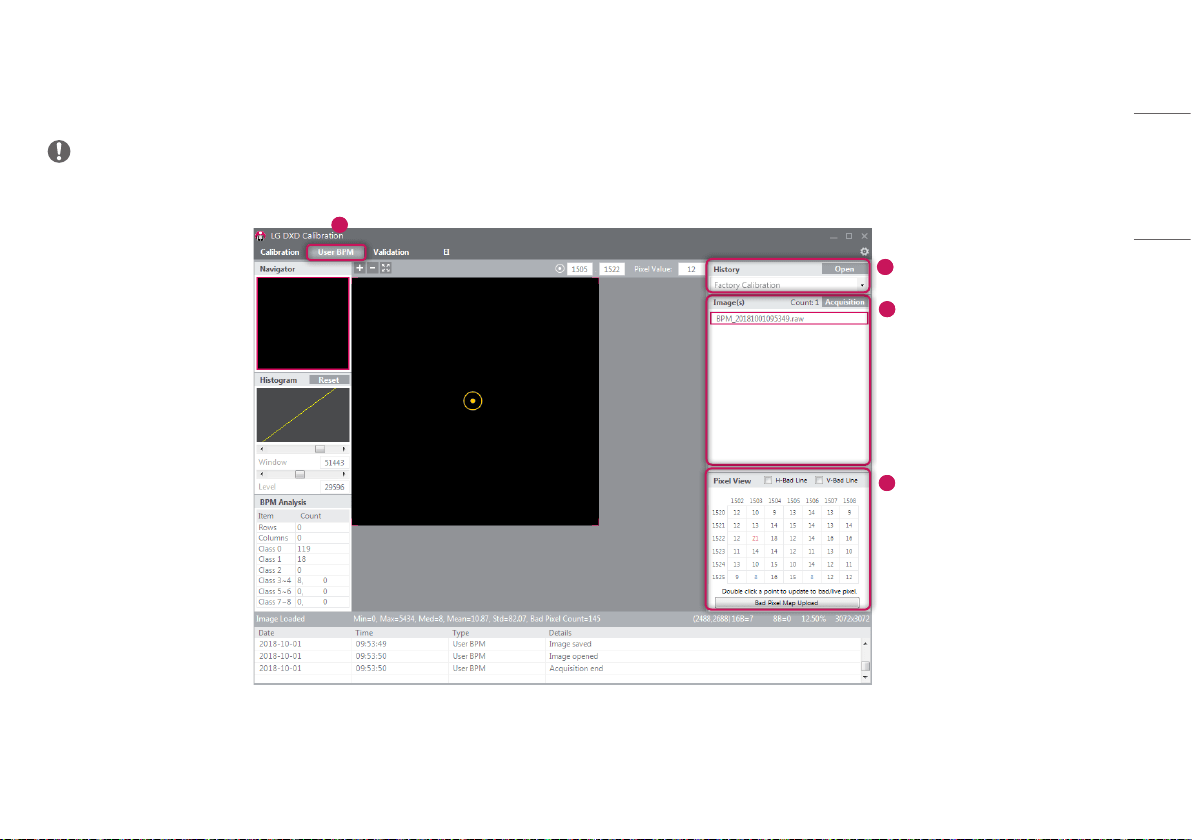
29
ENGLISH
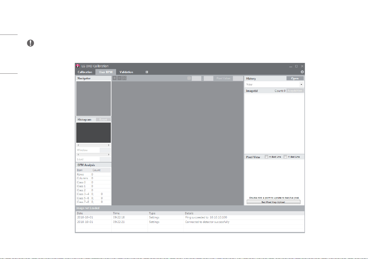
User BPM
Use this menu to manually edit the [Bad Pixel Map] created from the [Calibration].
NOTE
• You can skip the [User BPM] process and proceed with the [Validation] process.
1
2
3
4
30
ENGLISH
1
Enter into the [User BPM] menu
• Click the [User BPM] menu to enter.
• The [User BPM] requires image acquisition because it visually examines the image to which the result of
the [Calibration] is applied.
NOTE
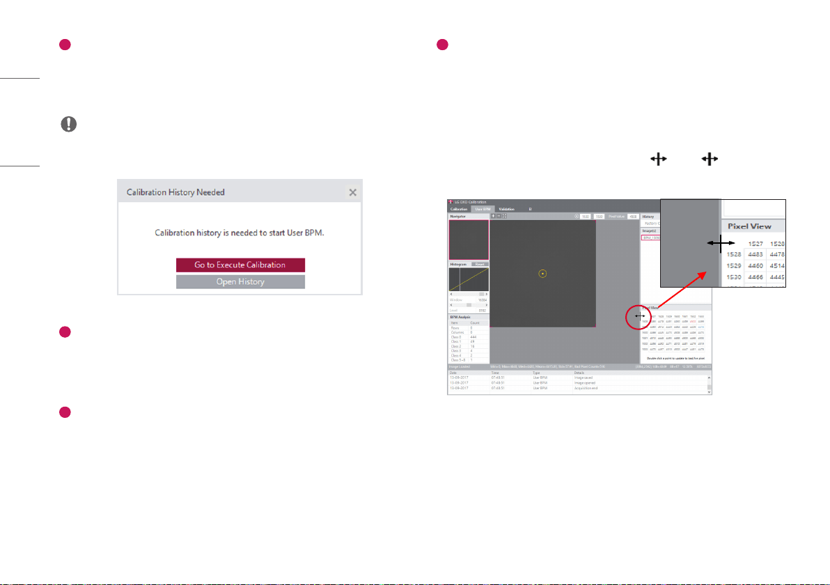
• The following pop-up appears when entering into the menu without completing the [Calibration].
2
Check the History file
• Check if the [History] name created from the [Calibration] matches the name shown in the current
[History] window.
• Apply the selected History file and carry out the [User BPM] process.
3
Acquire Images
• Click the [Acquisition] button and acquire a Bright Image. The image name will be shown in the
[Image(s)] list.
• The information about the image will be shown below the image view.
4
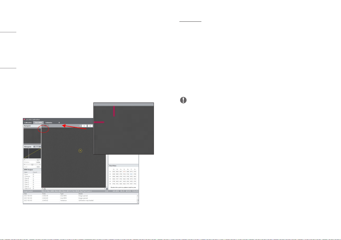
[Pixel View]
• Check the pixel values in the [Pixel View].
- Pixel values from the center of the image viewer are provided in the [Pixel View].
- Here, minimum value, maximum value, and possible Bad Pixel are shown as follows:
* Minimum value: Shown in blue numbers.
* Maximum value: Shown in red numbers.
* Possible Bad Pixel: Shown in the gray background.
- The window size of [Pixel View] can be changed using the icon. The icon appears when
hovering the mouse over the border between the [Pixel View] and the image viewer.
31
ENGLISH
• Set additional bad pixels in [Pixel View]
- Double click a pixel in the [Pixel View] to set the pixel as a bad pixel. Double-click the same pixel
specified as a bad pixel again to cancel the selection.
- If a pixel is set as a bad pixel, the value will be updated in the [BPM Analysis]. The specified bad pixel
will be replaced with the calibrated pixel value.
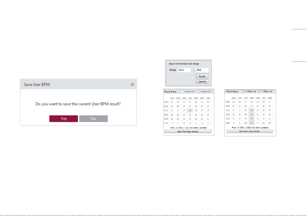
• Save the final [User BPM].
- When entering into another menu, the result file will be saved.
- A pop-up message appears asking to select whether to save the file when leaving the current menu
and entering into another one.
- When saved, one [History] is added and the [BPM.raw] file is updated and saved.
Assigning a Bad Lines in Pixel View
• When specifying Bad Pixel, it is a function to specify line unit instead of pixel unit.
• After checking the check box in the vertical or horizontal direction, double-click the pixel in [Pixel View]
to specify the line in the specified direction.
- If you specify a line from point 1522 to point 2600, select the [Apply] button after entering a value to
assign the line as a Bad Line.
32
ENGLISH
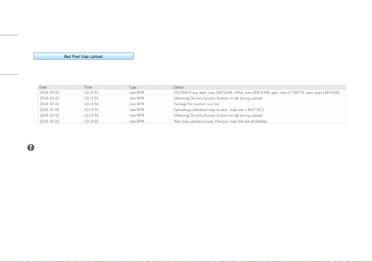
Bad Pixel Map upload function
• The newly modified Bad pixel map can be uploaded to the detector for use in future calibration.
• Press the [Bad Pixel Map Upload] button when you select some of the generated map files (BPM.raw, AvgDark.raw, Offset.raw, Gain.raw), upload them.
• If the upload is successful, it can be confirmed through the Log.
NOTE
• [Bad Pixel Map] When uploading, delete the map of the existing Factory Calibration folder. In order to preserve it, it must be done after backup in separate path.
• [Bad Pixel Map] When selecting a file to upload for upload, all four [Bad Pixel Map] files must be in the path. ([BPM.raw], [AvgDark.raw], [Offset.raw], [Gain.raw])
33
ENGLISH
Validation
This menu enables users to visually check the [Calibration] result after completing the [Calibration].
1
2
3
4
34
ENGLISH
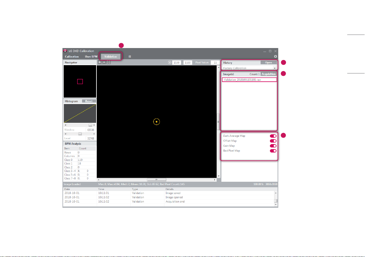
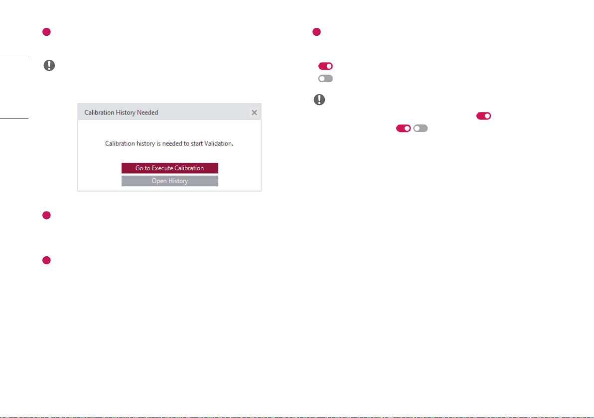
1
Enter into the [Validation] menu
• Click the [Validation] menu to enter.
NOTE
• The following pop-up appears when entering into the menu without completing the [Calibration].
2
Check the History file
• Check if the [History] name created from the [Calibration] matches the name shown in the current
[History] window.
3
Acquire Images
• Click the [Acquisition] button and acquire a Bright Image. The image name will be shown in the
[Image(s)] list.
• The information about the image will be shown below the image view.
4
Apply or Do Not Apply the Calibration Result
- You can decide whether to apply each of the Calibration results ([Dark Average Map], [Offset Map],
[Gain Map], [Bad Pixel Map]) to the image acquired.
: Apply
: Do Not Apply
NOTE
• When the first image is acquired and loaded, all results are set to .
• When no image is acquired, the / button is disabled.
35
ENGLISH
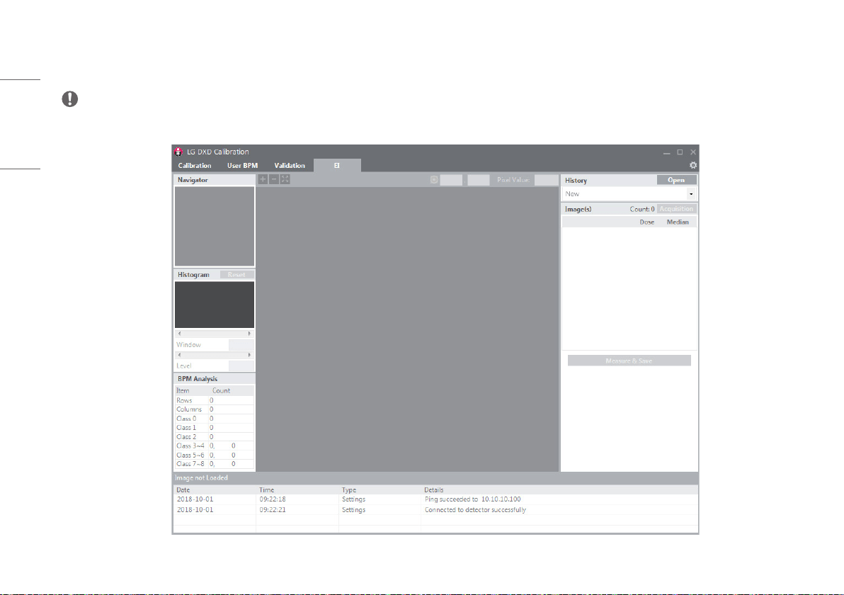
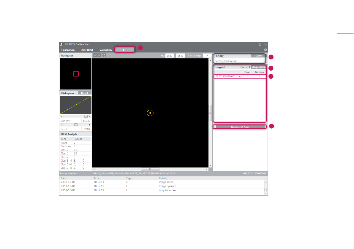
EI (Exposure Index)
The output median value based on the input Dose is calculated with a linear expression and in a table before being stored.
1
2
3
4
5
36
ENGLISH
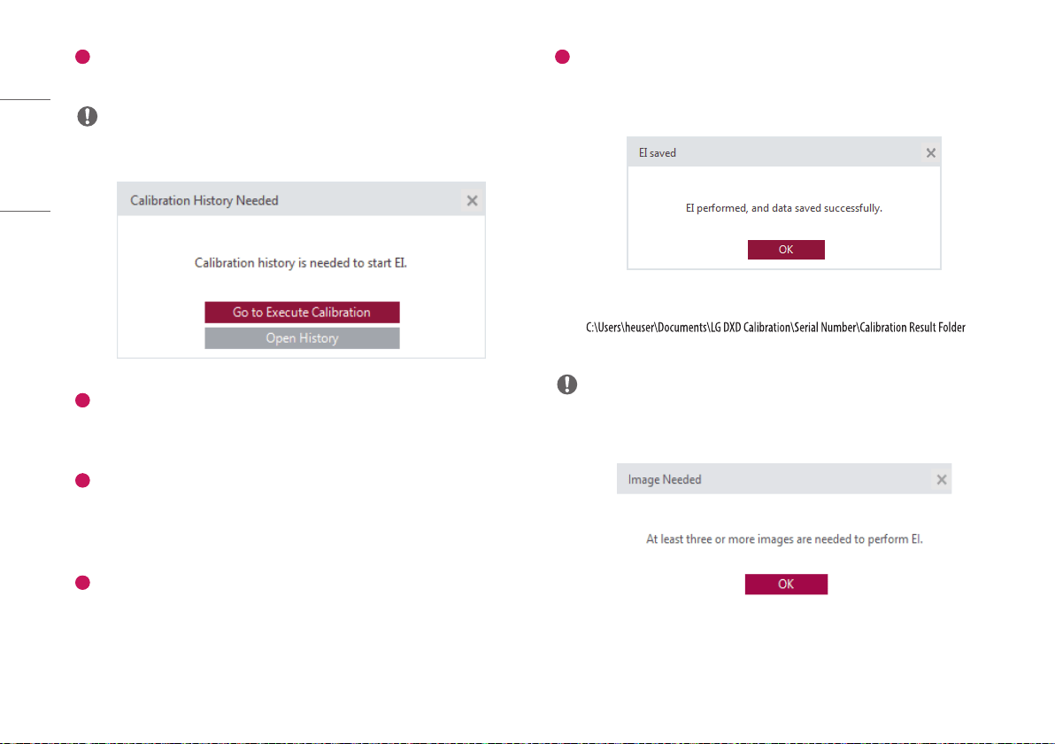
1
Enter into the [EI] menu
• Click the [EI] menu to enter.
NOTE
• The following pop-up appears when entering into the menu without completing the [Calibration].
2
Check the History file
• Check if the [History] name created from the [Calibration] matches the name shown in the current
[History] window.
3
Acquire Images
• Click the [Acquisition] button and acquire a Bright Image. The image name will be shown in the
[Image(s)] list.
• The information about the image will be shown below the image view.
4
Enter Dose Values
• The Dose values must be entered in the Dose field when X-ray irradiation is performed. (Unit: uGy)
• The EI value will be calculated based on the data entered.
• Dose values must be entered in numbers only. Texts will not be accepted by default.
5
[Measure & Save]
• Once image acquisition and dose value input are completed, click the [Measure & Save] button to save
the result value and show a pop-up message as follows:
• The EI result file will be saved in the same location as the Calibration result file.
(e.g. (date-
time) heuser: the user's name)
NOTE
• Repeating [Measure & Save] will update the result file.
• The following pop-up appears when the minimum requirement (3 images) is not met.
37
ENGLISH
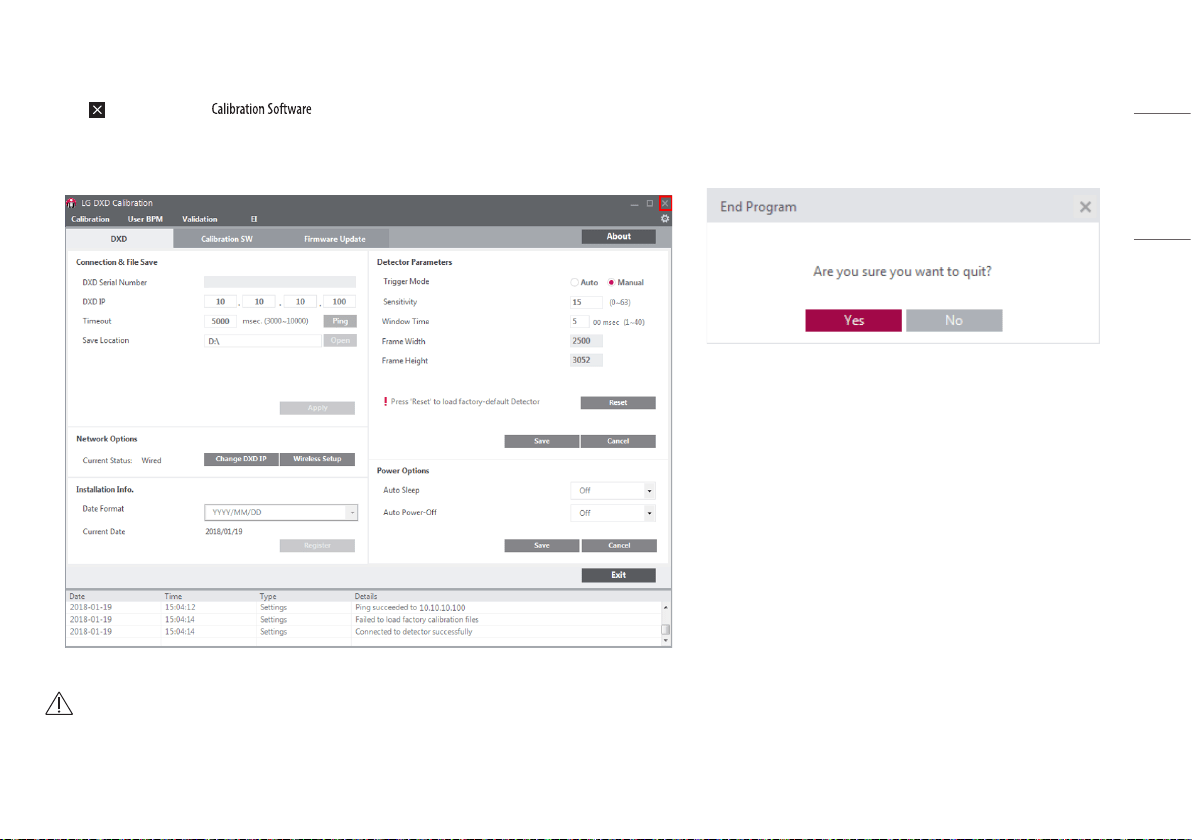
Exit
Click the (Exit) button to close .
Click the [Yes] button to close, or the [No] button to return to the last screen shown before the Exit button is clicked.
CAUTION
• Dark & Bright images will be deleted except Validation & raw images.
38
ENGLISH
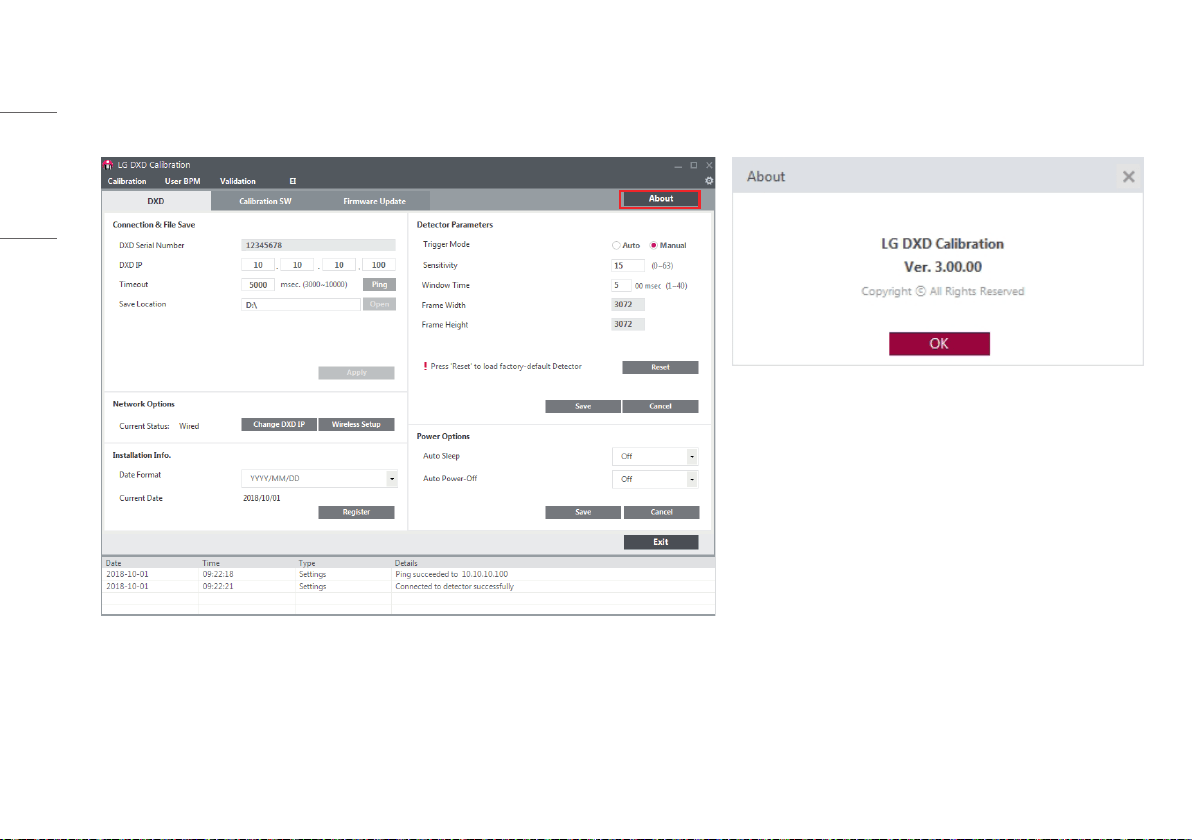
About
Click the [About] button in Settings to show a pop-up displaying the information about the application.
This pop-up provides the information about the application.
39
ENGLISH
General Pop-Up
General pop-ups available in are explained below.
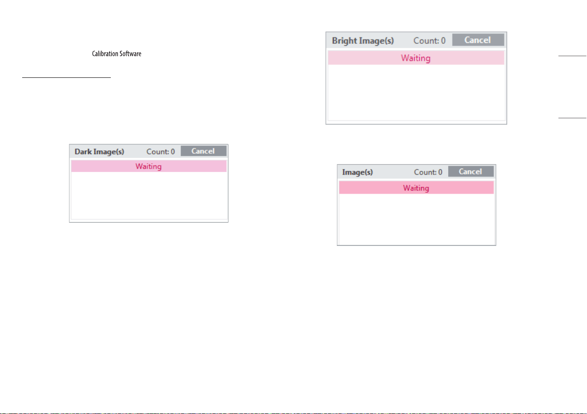
Cancelling Image Acquisition
• If you click the [Acquisition] button to acquire each image, the [Acquisition] button switches to the
[Cancel] button during the acquisition process.
• Once all the images are acquired, click the [Acquisition] button to return.
• Clicking the [Cancel] button while an image is being acquired will cancel the acquisition.
<The [Dark Image(s)] [Cancel] button>
<The [Bright Image(s)] [Cancel] button>
<The [Image(s)] [Cancel] button>
40
ENGLISH
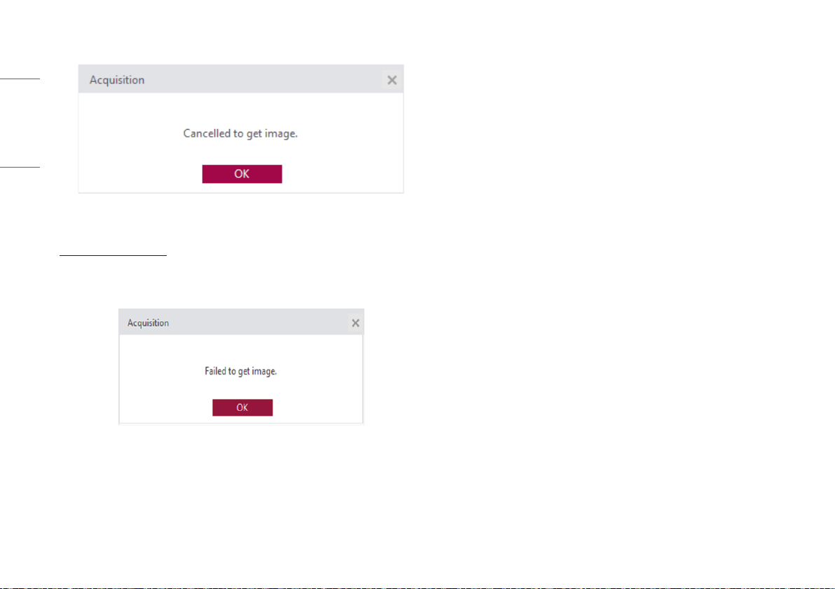
• The following pop-up appears when [Cancel] is successfully completed.
<The Get Image Cancel Completed pop-up>
Image Acquisition Failed
• If the image acquisition fails, the following pop-up message appears. Check the status of the network
and detector and try again.
<The Image Acquisition Failed pop-up>
41
ENGLISH
SERVICE MANUAL
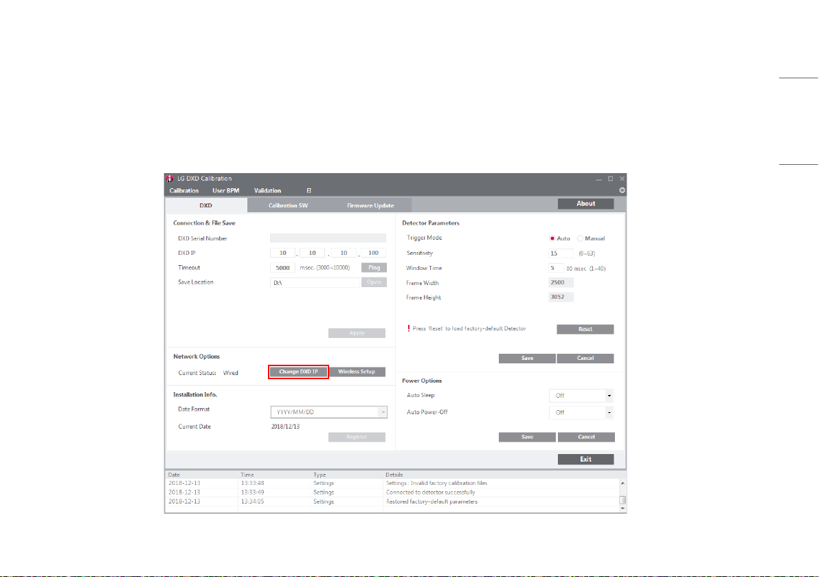
Setting IP address of Detector
1 Launch "Launching Program"> "IP Address Check and Ping Test"> "Save Location Check"> "Apply" in order.
2 Click the [Change DXD IP] button.
42
ENGLISH
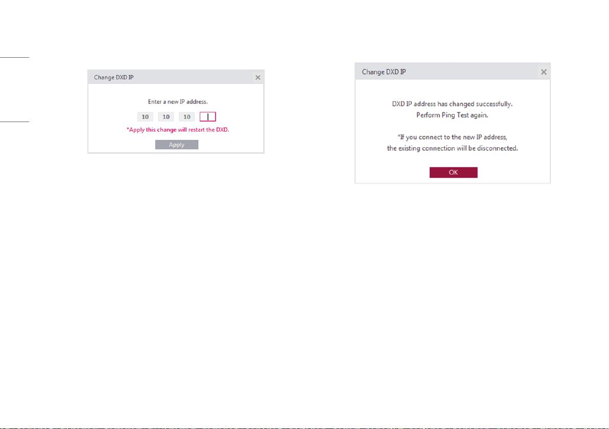
3 When a pop-up appears, change the settings and click the [Apply] button.
• Start changing the IP address by selecting the [Apply] button.
4 Check the result and re-boot the detector.
• A pop-up appears to with the following message whether the IP address is changed or not.
<A pop-up when the settings are made successfully>
• Once the IP address is changed, re-boot the detector to complete applying the changes to the IP.
• Click the [OK] button to automatically re-boot the detector.
• The detector will be disconnected during the re-boot process. Make sure to perform the [Connection &
File Save] process again.
43
ENGLISH
Wireless AP configuration
When the detector is connected wirelessly, AP information must be saved in the detector.
For station mode, enter the information of the external AP trying to access the detector. For AP mode, enter the information about the detector's AP.
• Default value of detector
- SSID: LGEDXD
- Password: @lgedxd2000
In station mode, the detector attempts to connect to the AP when the detector is rebooted after the AP information is saved in the detector. In AP mode, the detector uses its own AP, utilising the AP information saved
on the user PC. You can see the saved AP information by using the web monitoring function.
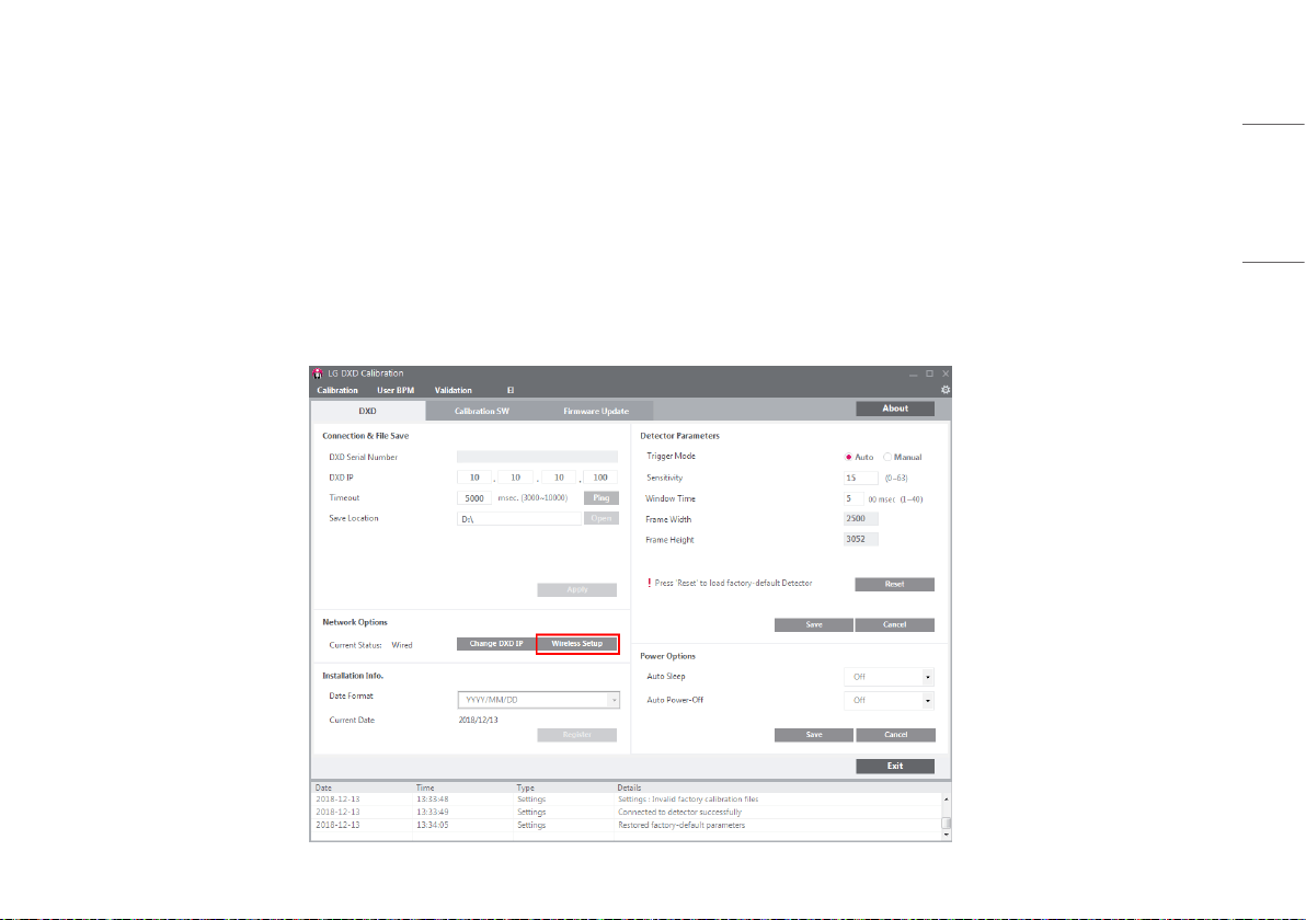
1 Launch "Launching Program"> "IP Address Check and Ping Test"> "Save Location Check"> "Apply" in order.
2 After checking that wireless settings are enabled on the PC, click the [Wireless Setup] button.
44
ENGLISH
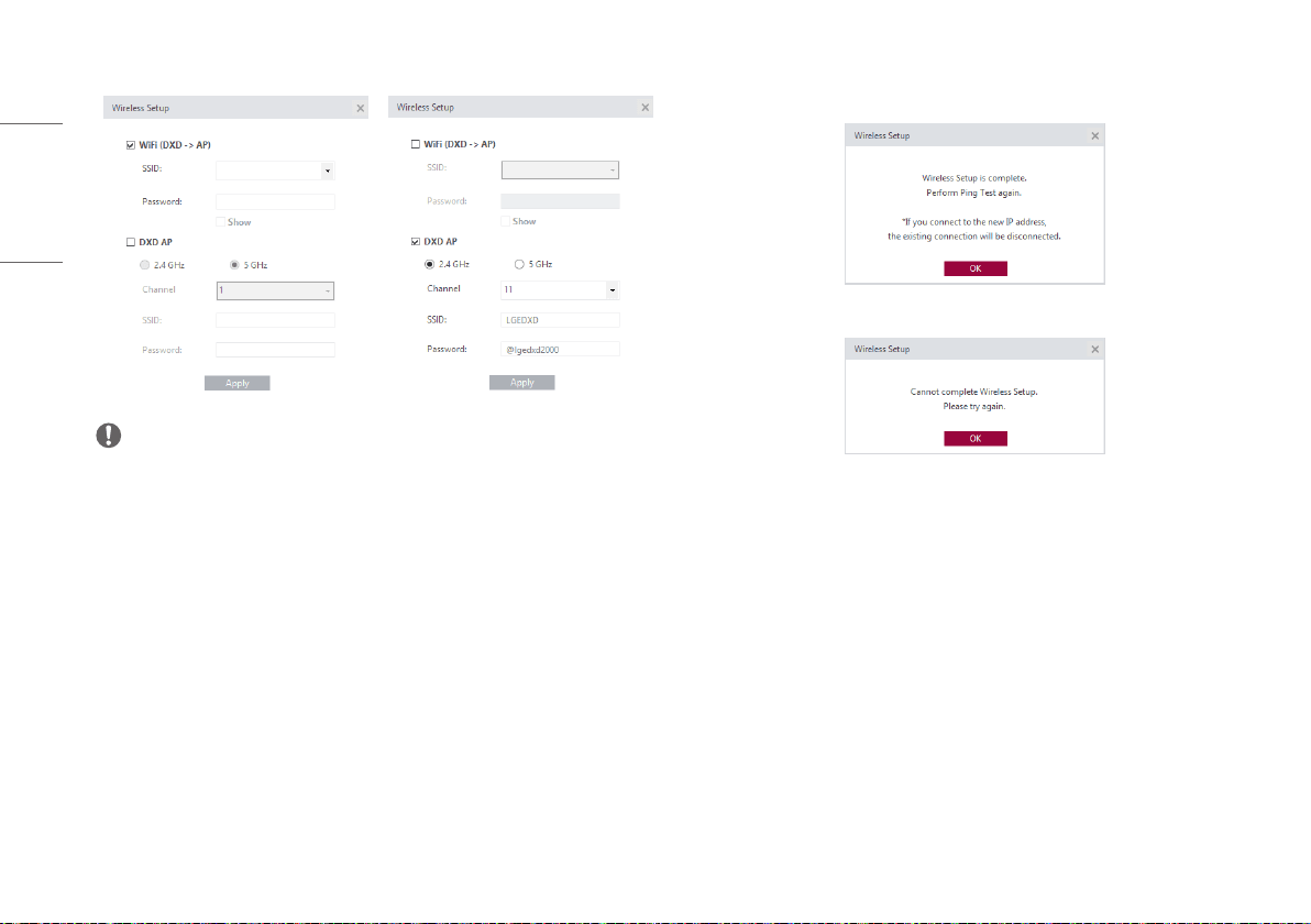
- If a pop-up appears, enter your [SSID] and [Password], then click [Apply].
NOTE
• Check the [Wi-Fi (DXD -> AP)] checkbox and enter the setting to use station mode.
• Check the [DXD AP] checkbox and enter the setting to use AP mode. The AP mode supports up to 11
channels (1-11) for the 2.4 GHz frequency. For the 5 GHz frequency, it only supports one channel.
• SSID can appear garbled, question marks, boxes, and others because of encoding or compatibly.
3 Check results.
- The following pop-up windows appear, depending on the result.
<Pop-up Window for Successful Configuration>
<Pop-up Window for Failed Configuration>
45
ENGLISH
Updating Detector Firmware
Use this menu to check and update the firmware version of the detector.
1
3
2
4
5
46
ENGLISH
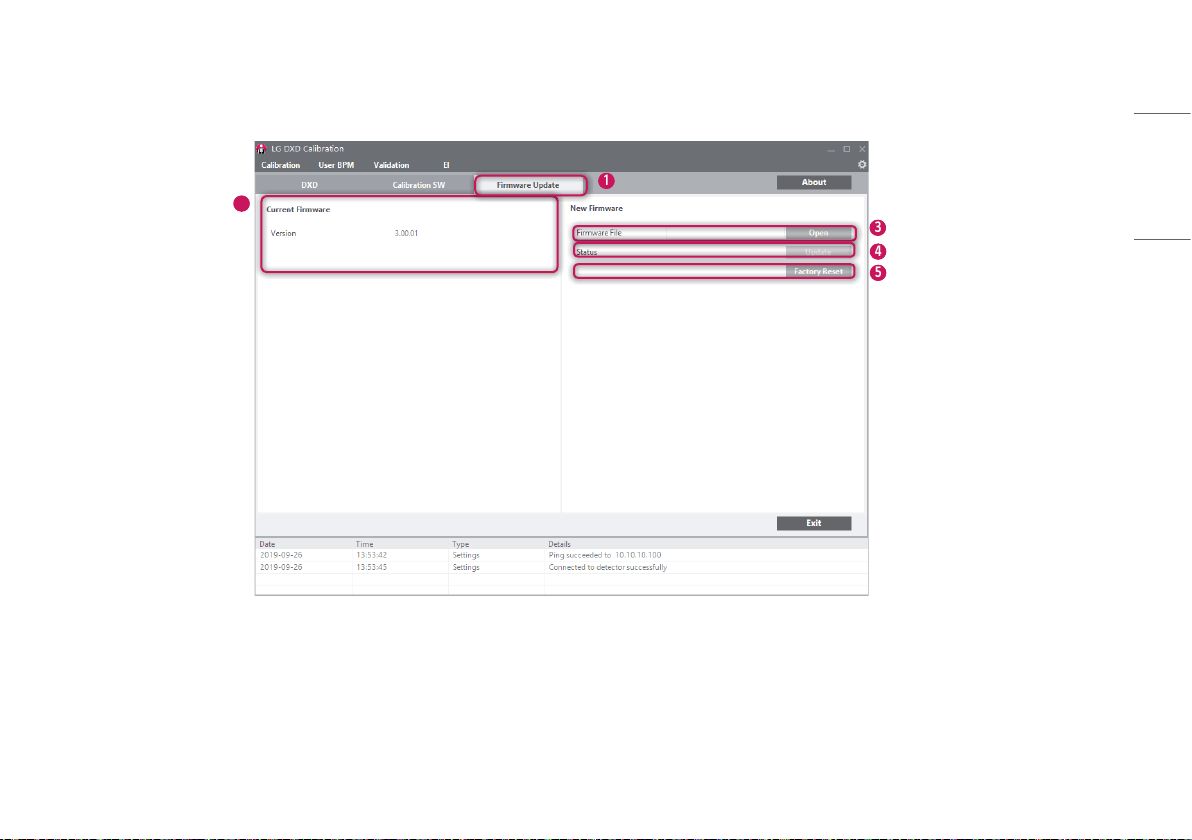
1
Select the [Firmware Update] tab.
2
Check the current firmware version.
• The current firmware version of the detector is indicated, and the version appears when a PC is
connected to the detector.
3
Select the firmware file to update.
• Click [Open] to launch a file explorer. Select the file to update to perform a check to validate the selected
file.
• If it is a correct firmware file, its name will be shown in the [Firmware File].
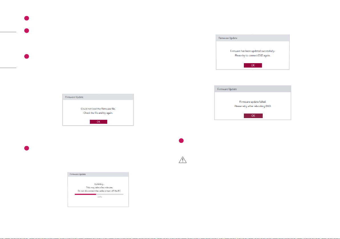
• If an incorrect file is selected, the following pop-up appears.
<A pop-up when the file loading fails>
4
Update the file.
• Select the file and click the [Update] button to start updating the firmware.
• The progress will be indicated in the [Firmware Update].
<A pop-up during file updates>
• Check the result.
- The following pop-up appears when the update is completed.
<A pop-up when the file update is completed successfully>
<A pop-up when the file update fails>
5
[Factory Reset]
• Clicking the button will reset all the DXD settings.
CAUTION
• Do not remove the power cable until the update is completed. If the detector is turned off while the
update is in progress, it may not work properly.
47
ENGLISH
Saving Installation Date
The first Calibration date can be saved in the detector.
1 Launch "Launching Program"> "IP Address Check and Ping Test"> "Save Location Check"> "Apply"
in order.
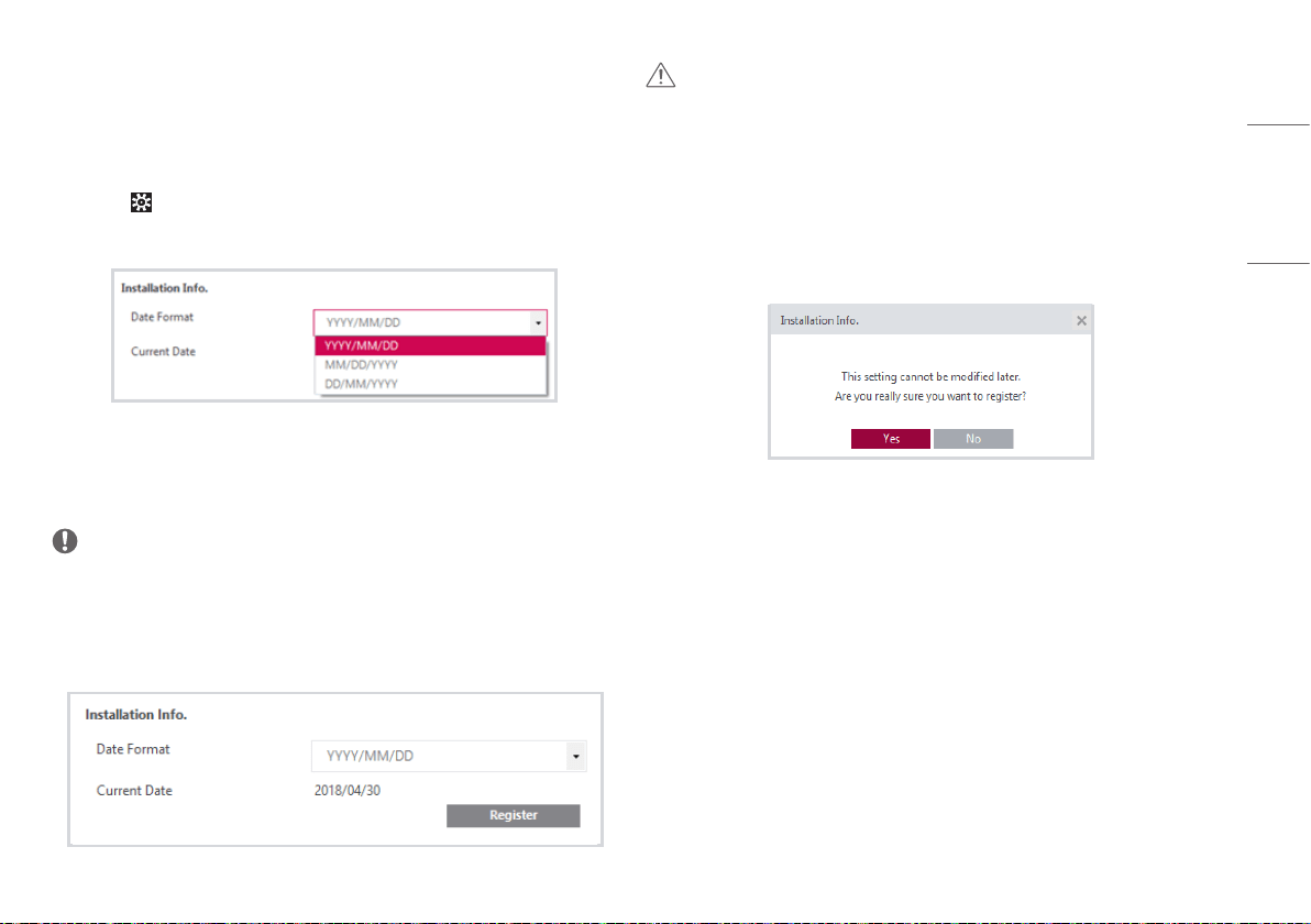
2 Select the > [DXD] tabs.
3 Check the installation date and choose the date format to be displayed.
- YYYY: Year
- MM: Month
- DD: Day
NOTE
• The date will be loaded based on the date and time set in the PC that runs the program.
4 Select the [Register] button to open a pop-up. The installation date can be checked using the Web
Monitoring feature.
CAUTION
• Please be careful to select the feature because this feature can be only saved once per detector and
cannot be edited.
• You must proceed when using the detector for the first time. Otherwise, you will not be able to enter
the menu.
5 Select the [Yes] button in the pop-up to store the information in the detector and disable the
[Register] button.
48
ENGLISH
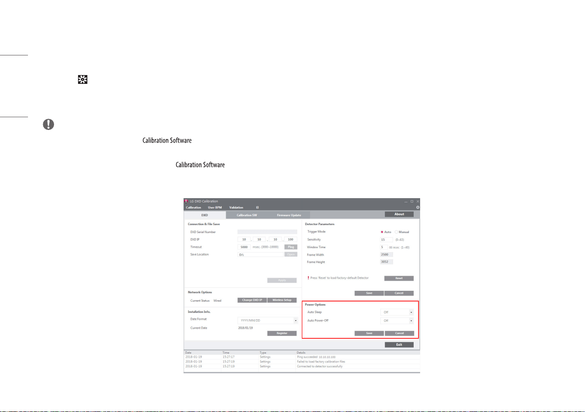
Setting Power Options
The [Power Options] can be saved in the detector.
1 Launch "Launching Program"> "IP Address Check and Ping Test"> "Save Location Check"> "Apply" in order.
2 Select the > [DXD] tabs.
3 Select the option in [Auto Sleep] and [Auto Power-Off].
4 Click the [Save] button to save the [Power Options] in the detector.
NOTE
• Only the above settings will be saved in .
• The detector enters into Standby mode when there is no communication for a set period of time.
• The detector does not enter into Standby mode while is running (i.e., starting from Apply to the point the program ends).
• This feature is enabled in a wireless model only.
49
ENGLISH
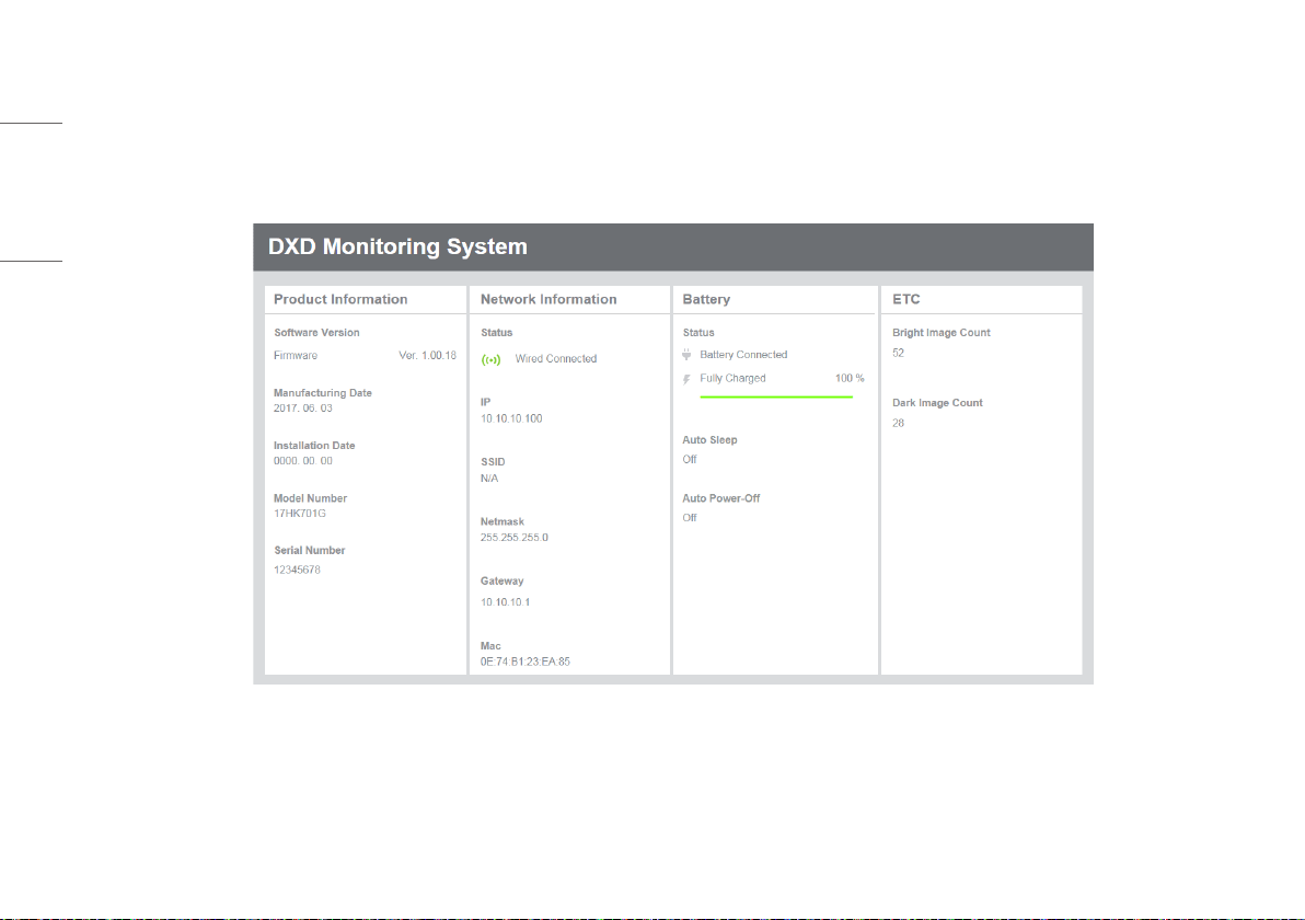
Web Monitoring
This feature allows users to check internal information such as shipping date, installation date, software version, etc. of the detector using a web browser.
Internal Information
Category Content Explanation
Product Information Software Version • Version of the firmware currently installed in the detector
Shipping Date • Date on which the product is manufactured
Installation Date • Date on which the product is installed by the installation engineer
Model No. • Model number of the product
Serial No. • Serial number of the product
Network Status of connection • Mode of network connection
IP • IP address of the detector
SSID • Wireless AP SSID
Netmask • Netmask of the detector
Gateway • Gateway of the detector
Mac • Mac address of the product
Battery Status • Battery level, charged level alert, auto standby, auto power-off
Others Bright Image Count • No. of image acquisitions with X-ray exposure
Dark Image Count • No. of image acquisitions without X-ray exposure
50
ENGLISH
Web Monitoring
1 Makes the wired/wireless connection between the detector and a PC.
- Please refer to the "Detector and PC".
2 Enter the detector's IP address in the address field of the web browser in the PC.
3 Default IP address: 10.10.10.100 The following page appears:

51
ENGLISH
MAINTENANCE
Cleaning
• Start cleaning after turning off the detector.
Test
• Carry out a regular test before use to ensure stable and normal operation of the detector. If the problem occurs, contact the manufacturer.
• Please perform tests based on items listed in the checklist below.
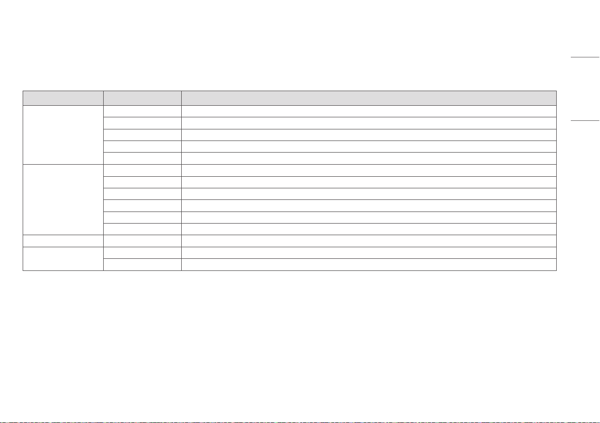
Checklist Tester Interval of Test
Are the cables damaged? User Daily
Are plugs or terminals loose or damaged? User Daily
Is the detector surface scratched or cracked? User Daily
Is the LED power working normally? User Daily
Perform a regular Calibration test Supplier 3-6 months
Conduct a performance test Supplier 1 year
52
ENGLISH
TROUBLESHOOTING
If you encounter problems when using the detector, use the guide provided in the corresponding section to solve the problem. If the problem persists, please contact the manufacturer.
Problem Solution
When the detector is not turned on • Check if the main cable is connected properly.
• Disconnect and reconnect the main cable.
When the detector is suddenly turned off
during the use
• Check if the main cable is connected properly.
When the LEDs of / parts on
the control box blink in orange
• Check the status of the power cable connection of the Control Box.
• Check if the Control Box is properly connected to the X-ray generator or detector.
When the detector is not connected to
the PC
• Check if the power is on. If the power is on, check the following items.
• Check if they are connected in accordance with the instructions in the manual. Try connecting again.
• Go to > [DXD] > [Connection & File Save] in and run a [Ping Test] to check the connection. Alternatively, open a browser window and enter an
IP in the address bar to check if a page is loaded properly.
• Check if the PC's network IP uses the same IP as the detector.
• In some cases, a connection issue may occur especially because of the firewall rules that block all ICMP packets coming from Win 8 OS. Please refer to the
Troubleshooting Firewall Issues.
When there is a problem with the status of
the acquired image
• Make sure that there is no foreign matter on the surface of the detector.
• If an image is acquired immediately after turning on the detector, a poor image may be acquired due to an unstable panel. Open the [Calibration] menu in
and acquire a couple of Dark Images first, or wait for a while and try again.
• If the image is still unstable, run a [Calibration] and apply the result before proceeding.
53
ENGLISH
Problem Solution
When some areas appear abnormal in the
acquired [Validation] image
• When acquiring images in the [Validation] after creating the [Calibration] result file in the Calibration menu, an abnormal image may be acquired. Check the issues
below and follow the guide.
1 When some areas appear in black or light bleeding occurs in the acquired image
- Go to the [Calibration] menu > [BPM Analysis] on the left bottom corner and check if [Rows] and [Columns], [Class] 5 ~ [Class] 8 have more than dozens of values. If so,
follow the steps below to run a new [Calibration] and acquire [Validation] images.
1) Adjust the X-ray generator's position so that the detector is within the X-ray irradiation range before running a [Calibration].
2) Keep the distance at least 120 cm (47.2 inch) between the detector and the X-ray generator tube.
3) If the distance cannot be more than 120 cm (47.2 inch) in Step 2), change the detector settings as follows before proceeding with the [Calibration].
Go to > [Calibration SW] and enter a value 0.05-0.1 higher than the existing value for [Gain] and [Save].
Go to > [Calibration SW] and enter a value 1.5-2 times greater than the existing value for [Offset] and [Save].
NOTE
• Due to the heel effect of the X-ray generator, if the distance is short, less X-ray irradiation may be applied to the edge of the detector. This difference makes it necessary
to adjust the [Gain] and [Offset] values. The [Gain] adjustment is a required process, but the [Offset] adjustment may be skipped depending on the situation.
4) Go to the [Calibration] menu and acquire Dark Image and Bright Image to run a [Calibration]. If the [BPM Analysis] result is not improved, repeat Step 3).
2 When some areas appear in black in the form of the straight or curved line
- Check if the problematic area is within the X-Ray irradiation range.
- Check if foreign matters or other objects are on the detector.
3 When white or black pixels appear in the image
- Run a [Calibration] again to create a new Calibration result, and, with the result, acquire [Validation] images.
- It the problem persists even after the new Calibration, set the pixel as a bad pixel in the [User BPM] and go to [History] > [Open] on the top right corner to load the
newly created calibration result and perform a [Validation] again.
54
ENGLISH
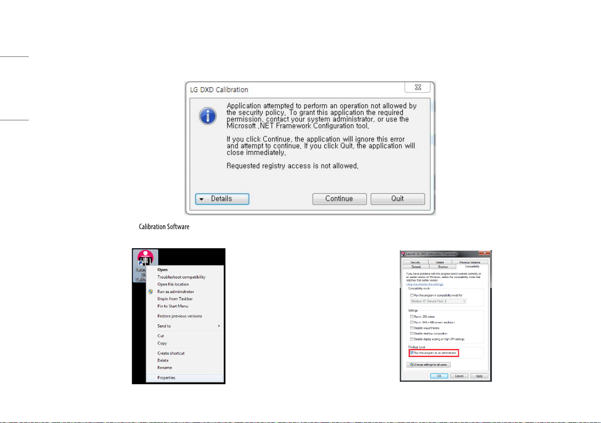
PROGRAM NOT LAUNCHED DUE TO ACCESS PRIVILEGE ISSUES
1 When the program is not launched with the following pop-up after going to "Launching Program"> "IP Address Check and Ping Test"> "Save Location Check"> "Apply", check the following items.
2 Right-click the launching icon of and select [Properties]. 3 In the [Properties] window, enter into the [Compatibility] tab and select the Run this program as
an administrator checkbox under the [Privilege Level].
55
ENGLISH
TROUBLESHOOTING FIREWALL ISSUES
If the Link LED is off on the DXD set due to Windows Firewall, follow the steps below.
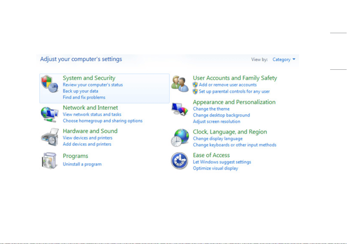
1 Go to [Control Panel] and select the [System and Security] menu.
56
ENGLISH
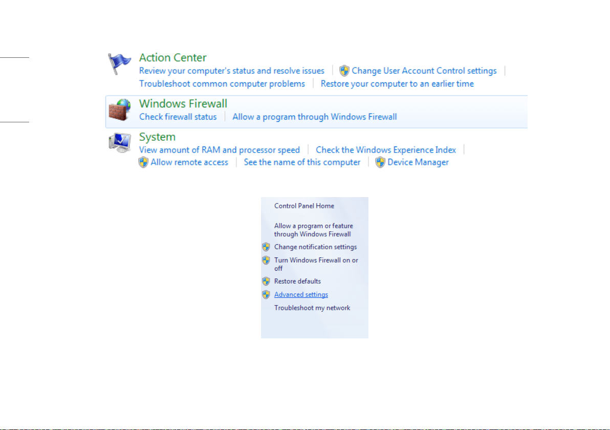
2 Click the [Windows Firewall] link.
3 On the left side of the pane, click the [Advanced Settings] link.
57
ENGLISH
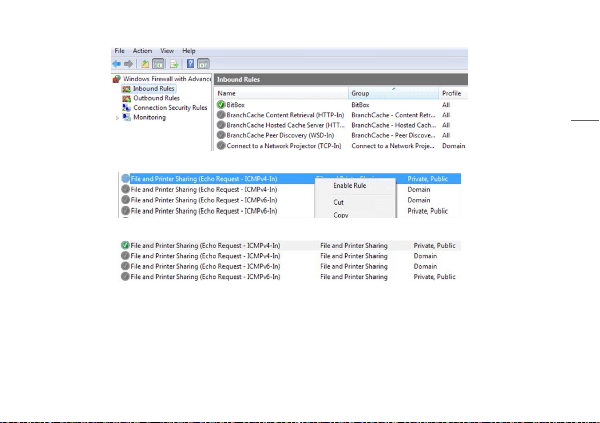
4 Under the Windows Firewall with Advanced Security, select [Inbound Rules].
5 Scroll down to find the [File and Printer Sharing] rule and click [Enable Rule].
6 Check the status and connect the detector again.
58
ENGLISH
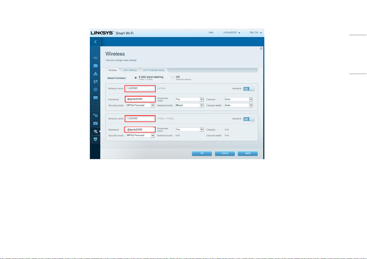
WIRELESS
Wireless Access Point Setup Guide (Model: Cisco Linksys EA9200)
1 Connect the LAN Cable from the Ethernet port on the PC to the Ethernet port on the AP.
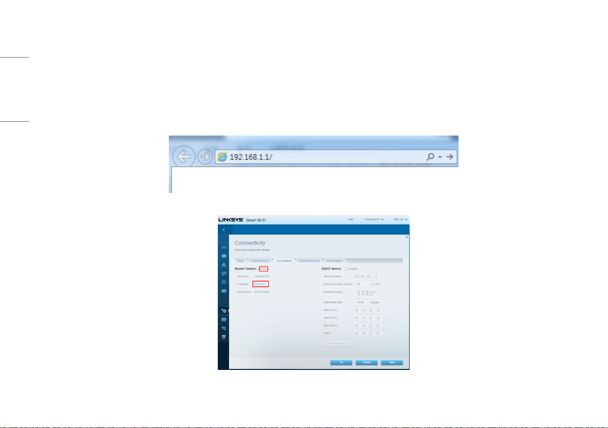
2 Launch your web browser and enter linksyssmartwifi.com or http://192.168.1.1 in the Address bar then press Enter. (IP number address for the 1st access is 192.168.1.1. However, IP number address for
accessing will be 10.10.10.1 after changing 10.10.10.1)
Enter into [Connectivity] > [Local Network]. Click [Edit] to change IP address to 10.10.10.1.
(You should click [Apply] button to apply current setting)

WARNING: This equipment is compliant with Class A of CISPR 32. In a residential environment this equipment
may cause radio interference.
The model and serial number of the product are located on the back and on one side of the product. Record them
below in case you ever need service.
Model
Serial No.
Supplier’s Declaration of Conformity
Trade Name LG
Responsible Party LG Electronics USA, Inc.
Address
111 Sylvan Avenue, North Building,
Englewood Cliffs, NJ 07632
E-mail lg.environmental@lge.com
