Loading ...
Loading ...
Loading ...

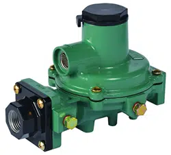
R122H, R222H, R222, R232A and R232E Series
LP-Gas Regulators
6
• Install the regulator so that any gas discharge
through the vent or vent assembly is over 3 ft. / 0.9 m
horizontally from any building opening below the level
of discharge.
• Install the regulator high enough above ground level - at
least 18 in. / 46 cm - so that rain splatter cannot freeze
in the vent.
Regulators Subjected to Heavy
Snow Conditions
Some installations, such as in areas with heavy snowfall,
may require a hood or enclosure to protect the regulator
from snow load and vent freeze over.
Horizontally Installed Regulators
Horizontally mounted regulators, such as found in single
cylinder installations and ASME tanks, must be installed
beneath a protective cover or under the ASME tank
dome, refer to Figure 3. If possible, slope or turn the vent
down sufciently to allow any condensation to drain out of
the spring case. Be careful that the slot in the tank dome
or protective cover for the regulator’s outlet piping does
not expose the vent to the elements. The rst stage vent
on the Types R232A and R232E should be pointed down.
Indoor Installations
The Types R122H, R222H, R232A and R232E regulators
are not recommended for indoor installations. The
Type R222 regulator may be installed indoors as follows.
By code, regulators installed indoors have limited inlet
pressure and they require a vent line to the outside of the
building, see Figure 4. A vent assembly, such as Fisher
®
Y602 Series, should be used on the end of the vent line.
The same installation precautions, previously discussed
throughout this manual for the regulator vent, apply to the
end of the vent tube assembly. Vent lines must not restrict
the gas ow from the regulator’s internal relief valve. Vent
lines should be at least 3/4 in. NPT pipe or 3/4 in. NPT
size, Gray PVC Schedule 40 Rigid Non-metallic Electrical
Conduit for above Ground Service, per UL
®
651. To install
the vent line, remove the vent screen and apply a good
grade of pipe dope to the male threads of the line. Vent
lines should be as straight as possible with a minimum
number of bends.
Underground Installations
!
WARNING
Types R232A and R232E integral regulators
require 2 vent tubes, one on the rst stage
vent and one on the second stage vent,
when installed on underground tanks.
Failure to use 2 separate vent tubes can
result in early regulator failure and/or over
pressuring the second stage that could
result in res or personal injury.
A regulator installed in the dome of an underground
container requires a vent tube to prevent water from
entering the regulator spring case, see Figure 5.
The Types R122H and R222H will require one vent line
and if the Types R232A and R232E integral regulators is
installed on an underground tank the use of 2 vent tubes
are required, one for the rst stage vent (1/4 in. OD copper
tube inverted are connection: 7/16-24 UN thread) and the
other for the second stage vent (3/8 NPT) of the regulator,
are required.
Remove the vent screen(s) and install vent tube(s). The
vent tube must be run from the regulator vent(s) to above
the maximum water table. The vent tube opening(s) must
terminate at the extreme top inside of the dome cover.
Make sure the regulator’s closing cap is on tightly and
maintain drainage away from the dome at all times.
Outdoor Installations with Underground
Vent Lines
When installed per code, the underground vent line must
not restrict the gas ow from the regulator’s internal
relief valve and must remain clear of debris, dry and fully
open at all times. Joints in the vent line must be fully
sealed to prevent moisture intrusion into the vent line. A
vent assembly, such as the Fisher Y602 Series, should
be used on the end of the vent line to prevent entry of
precipitation, water or other debris. When underground
vent lines are used in humid environments, the vent line
must be designed to allow for proper drainage of any
collected moisture or condensation.
Adjustment
Each regulator is factory set. If it becomes necessary to
increase the outlet pressure, remove the closing cap and
turn the adjustment screw clockwise. Turn the adjusting
screw counterclockwise to decrease the outlet pressure.
The rst stage portion of the Types R232A and R232E
integral regulators is non-adjustable.
The inlet and outlet pressure tap plugs on the R122H,
R222H, R222, R232A and R232E Series regulators may
be removed using a 7/16 in. / 11 mm hexagon wrench.
The pressure tap is restricted, so the plug can be removed
with pressure in the regulator. Install a pressure gauge to
determine the regulator’s inlet pressure and outlet setting
during adjustment, (Actual pressure at the second
stage
regulator may be less due to line loss.). After setting, add
thread sealant to the 1/8 in. NPT pipe plug. Reinstall the
pipe plug by threading it into the gauge port nger-tight and
then wrench tighten the plug 1-1/2 to 3 turns past nger
tight (approximate maximum torque of 12 ft-lbs / 16 N•m).
Replace the closing cap. Check the plug for leakage.
UL
®
is a mark owned by Underwriters Laboratories.
Loading ...
Loading ...