Version 1.4
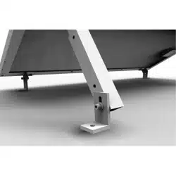
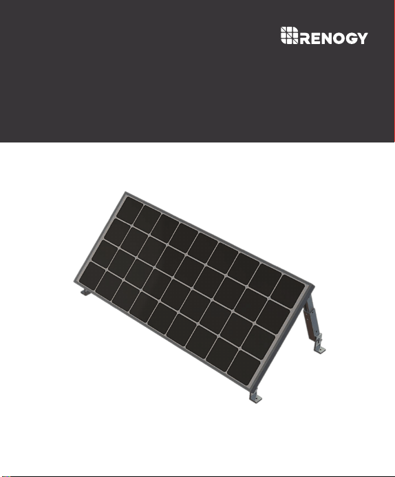
Flat Roof Tilt Mount
MTS-TM100
General Safety Information
Installer Responsibilities
Important Safety Instructions
Please save these instructions.
This manual contains important safety, installation, and operating instructions for the
charge controller. The following symbols are used throughout the manual to indicate
potentially dangerous conditions or important safety information.
Chance to strip nuts and bolts exists.
This system is NOT possess any compliance with residential structural codes and
should not be used in place of a system that is, if so required by local regulations
Do NOT substitute parts from other manufacture ring sources, doing so may void the
warranty and/or result in an unstable system
Read all the instructions and cautions in the manual before beginning the installation.
Installation compliance with any applicable codes which are in force at the installation site.
Installation compliance and compatibility with all system components and the
environment including but not limited to roofing, system components, etc.
Verification that all project information is accurate
NOTE
CAUTION
WARNING
WARNING
Indicates a potentially dangerous condition. Use extreme caution when
performing this task
This equipment should be installed, adjusted, and serviced by qualified
electrical maintenance personnel familiar with the construction and operation of
the equipment and the hazards involved. Failure to observe this precaution may
result in bodily injury. Protective gloves and safety glasses should be worn
during installation.
Indicates a critical procedure for safe and proper operation of the controller
Indicates a procedure or function that is important to the safe and proper
operation of the controller.
01

Table of Contents
General Information
Identification of Components
Installation
Fasten L-Joint to Back of Solar Panel
Attach L-Joint to L-Bracket Foot
Attach Extension Bracket to L-Joint
Attach L-Bracket Foot to Extension Bracket
Mounting Recommendations
Dimensions
03
04
06
06
08
09
10
11
12
14
Compatibility
02
03
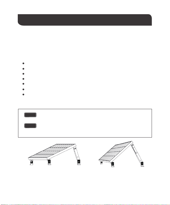
General Information
The Renogy Tilt Mount will support various mounting applications, especially in off-grid. It
is suitable for most Renogy panels and can be mounted on any flat surface. This mount is
designed to allow some adjustment of the panel’s angle for optimum performance. The
angle adjustability is dependent on the panel size, with larger panel sizes decreasing
angle adjustability.
The angles for the Renogy Tilt Mount are based off a landscape panel
installation. As the solar panel size increases, the angle freedom decreases.
5052-H32 aluminum construction
Stainless steel fasteners
High-tensile strength
Precision hole positioning and alignment
Easy, rapid assembly
Corrosion Free
Attractive brushed aluminum finish
Key Features
Angle Adjustability
NOTE
The following angles are a general framework based on extension bracket
length. The minimum angle maximizes the extension bracket length while the
maximum angle minimizes the extension bracket length.
NOTE
Maximum Angle° Minimum Angle°
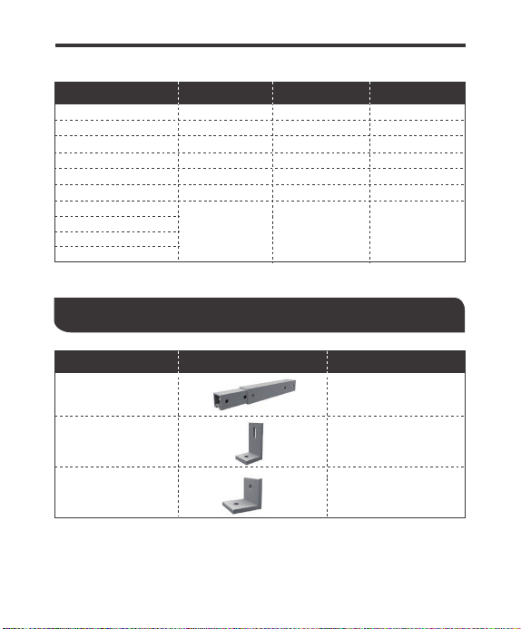
Identification of Components
Panel Models Minimum Angle° Maximum Angle° Degree Freedom
50W Mono
Extension Bracket
(A)
L-Bracket Foot
(B)
38
65 20
50W Poly
65 20
39
100W Eclipse
150W Mono
280W Mono
270W Poly
100W Mono
320W Poly
250W Poly
2065
89
100W Poly 51 70 15
36 64 28
64 77
76 12
2
4
13
64
Part Part Name Quantity
L-Joint
(C)
4
04
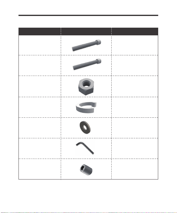
M8 Cap Bolt-55mm
(D)
M8 Cap Bolt-25mm
(E)
M8 Nut
(F)
M8 Spring Washer
(G)
4
6
10
10
M8 Flat Washer
(H)
20
4mm Hex Key
(I)
1
Set Screw
(J)
4
Part Part Name Quantity
05
06
Installation
The above tools and equipment are highly recommended to have available to assist with
installation but are in no way a comprehensive list of tools that can ease installation.
Installers feel free to substitute comparable equipment where appropriate.
The equipment should be installed, adjusted, and serviced by a qualified
electrical maintenance personnel familiar with the construction and
operation of the equipment and hazards involved. Failure to observe this
precaution may result in bodily injury. Protective gloves and safety
glasses should be worn during installation.
The stripping of the threads on the nuts and bolts is possible.
CAUTION
WARNING
Recommended Tools (Not provided)
Socket wrench
Torque extension
High-tensile strength
18mm wrench or socket for larger hex nut
13mm wrench or socket for smaller hex nut
Box-Leveler
Tape Measure
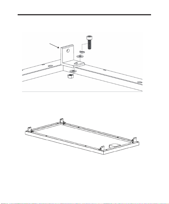
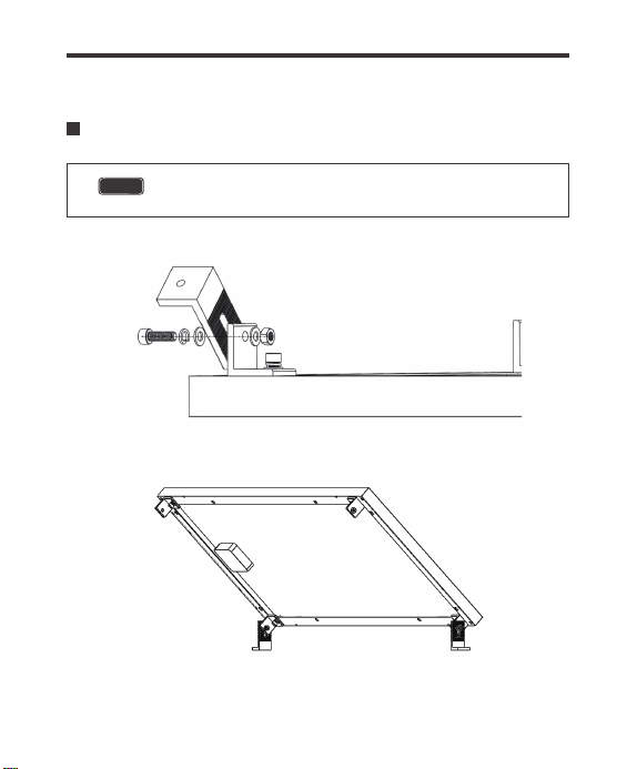
Fasten L-Joint to Back of Solar Panel
The back of the L-Joints face away from the panel’s longitudinal center.
NOTE
All Cap Head Bolts must have a Spring Washer and Washer before
feeding through a hole. A washer will also need to be placed behind the
hole before the nut.
NOTE
(C)
(E)
(G)
(H)
(H)
(F)
07
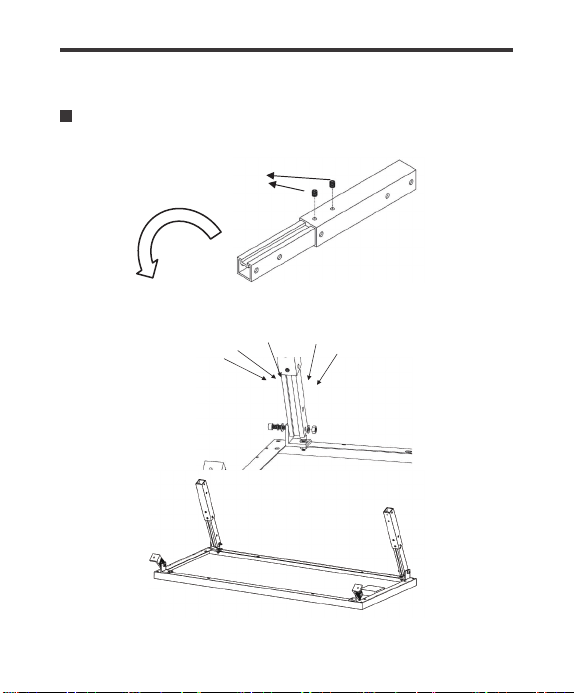
Attach L-Joint to L-Bracket Foot
The mounting angle demonstrated in the image is to serve as a guide for
users and their individual assemblies.
NOTE
(E) (G)
(H)
(F)
08
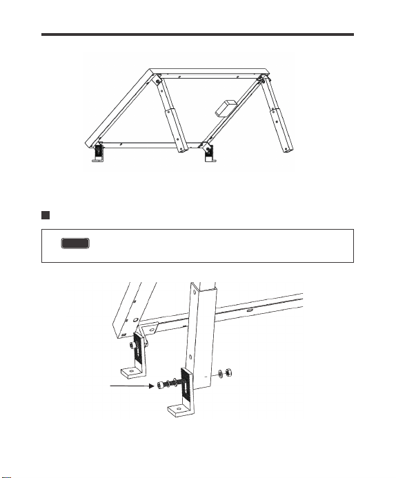
Attach Extension Bracket to L-Joint
(J)
(H) (H)
(F)
(G)
(D)
09
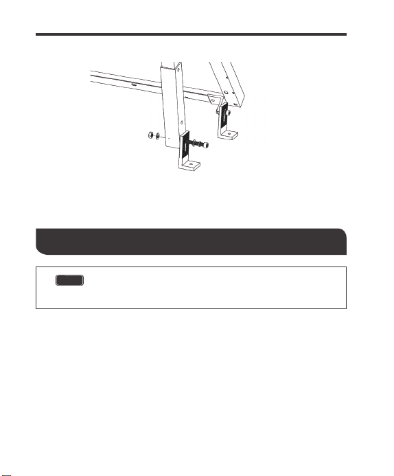
Attach L-Bracket Foot to Extension Bracket
The mounting angle of the Extension bracket relative to the L-Joint can
change based on user needs.
NOTE
(H)
(H)
(F)
(G)
(D)
10
Mounting Recommendations
There are various fastening techniques, but some of the most common situations call for the
use of a lag bolt. This method is common when mounting panels onto a roof with a wood or
asphalt surface. The following is a basic approach and should be taken as such.
Use a power drill with socket extension to drill the lag bolt into the hole.4.
Drill until sufficient load is applied.5.
2.
Drill 4 holes where the holes on the L-Bracket Feet line up. A power drill with a sufficient
drill but should be utilized in this process.
1.
Find a desired mounting location
3.
After the hole has been drilled, silicone sealant needs to be administered to the hole in
order to prevent leaks.
The following information is intended to be a basic guide to give the
user a basic approach to mounting. A proper roof-mounting guide
should be consulted prior to beginning any installation.
NOTE
11

12
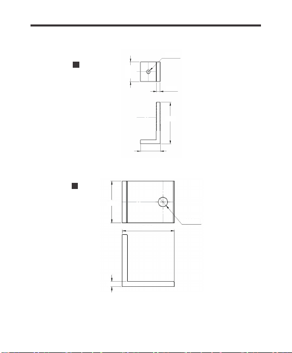
Dimensions
Inner Extension Bracket
The following drawings utilize inches as their dimension units.
NOTE
Outer Extension Bracket
8.86
1.24
8.86
1.50
φ0.26
13
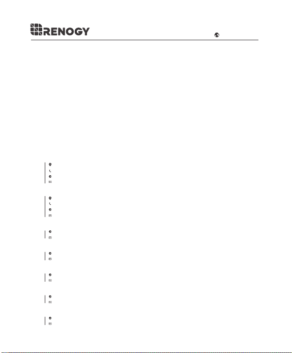
L-Foot
L-Joint
1.57
φ0.35
1.97
0.20
1.57
3.35
0.28
φ0.30
1.57

Compatibility
The following chart represents the Renogy Modules for which this Tilt Mount works for and is
optimized for. Optimization of the module implies that there are more degrees of freedom
tilting.
Compatibility*
RENOGY Solar Module
14
RNG-10D-SS
RNG-30D-SS
RNG-50D-SS
RNG-100D-R-BK
RNG-100D-SS
RNG-100MB
RNG-160D-SS
RNG-175D
RSP200D
RNG-270P
RNG-300D
RNG-320D
IMCOMPATIBLE
IMCOMPATIBLE
OPTIMIZED
OPTIMIZED
OPTIMIZED
OPTIMIZED
WORKS
WORKS
WORKS
WORKS
WORKS
WORKS
Renogy reserves the right to change
the contents of this manual without notice.
RENOGY.COM
US
2775 E Philadelphia St, Ontario, CA 91761, USA
909-287-7111
www.renogy.com
support@renogy.com
https://www.renogy.cn
support@renogy.cn
CN
400-6636-695
苏州高新区科技城培源路1号5号楼-4
CA
https://ca.renogy.com
supportca@renogy.com
https://au.renogy.com
supportau@renogy.com
AU
JP
https://www.renogy.jp
supportjp@renogy.com
https://uk.renogy.com
supportuk@renogy.com
UK
https://de.renogy.com
supportde@renogy.com
DE