Loading ...
Loading ...
Loading ...
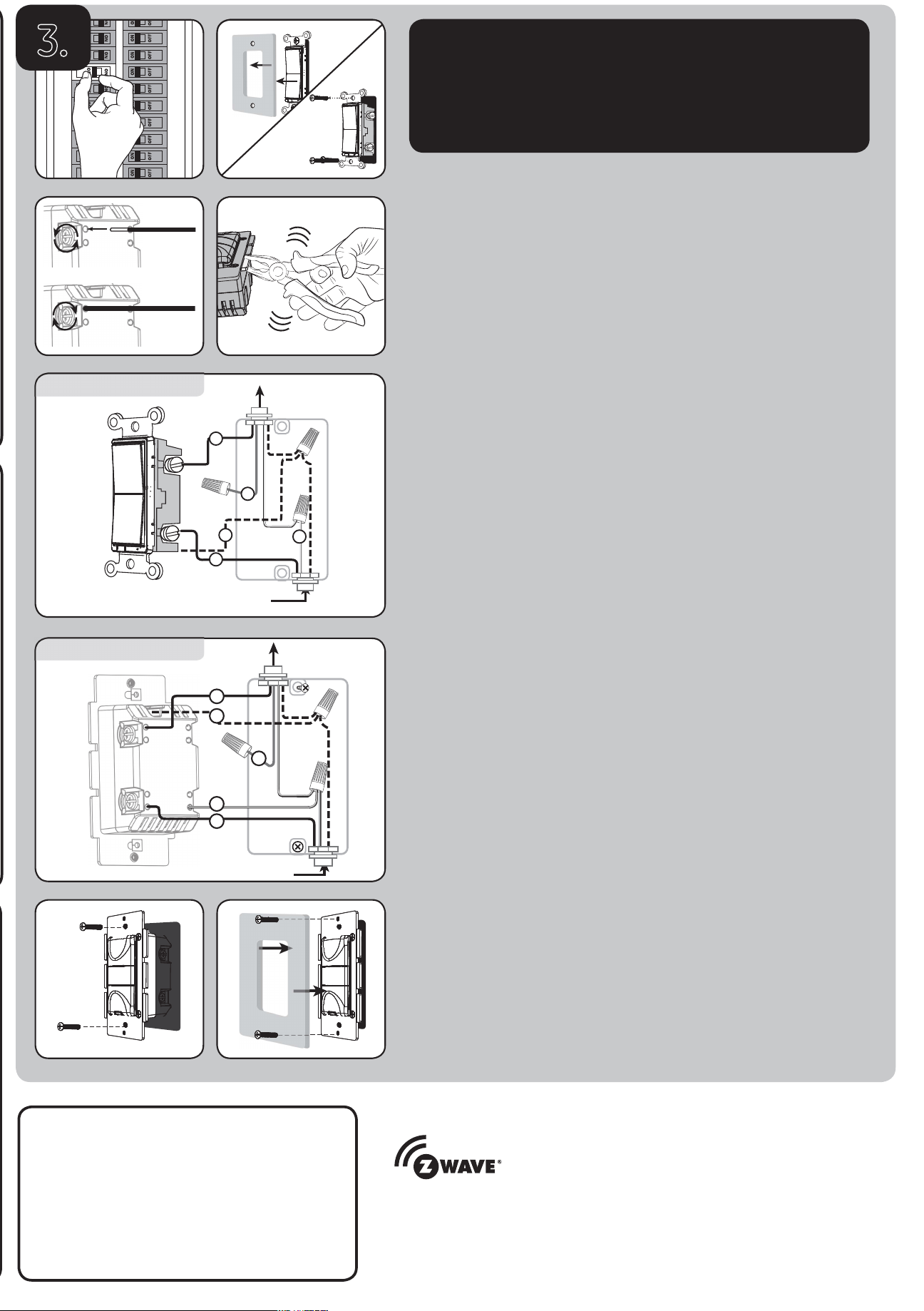
From Breaker Box
Out to Light (Load)
C
E
D
A
B
C
A
D
B
E
From Breaker Box
Out to Light (Load)
This device supports Association Command Class (3 Groups)
• Association Group 1 supports Lifeline, Multi Level Report
• Association Group 2 and Group 3 support Basic Set and are controlled by pressing
the ON or OFF button with the local load
• Each Association Group supports 5 total nodes
For more details, visit ezzwave.com
Z-WAVE INTEROPERABILITY
This product can be included and operated in any Z-Wave network with
other Z-Wave certified devices from other manufacturers and/or other
applications. All non-battery operated nodes within the network will act as
repeaters regardless of vendor to increase reliability of the network.
WARNING — SHOCK HAZARD
Turn OFF the power to the branch circuit for the switch and lighting fixture at the service
panel. All wiring connections must be made with the POWER OFF to avoid personal injury and
damage to the switch. This device is intended for installation in accordance with the National
Electric Code and local regulations in the United States, or the Canadian Electrical Code
and local regulations in Canada. If you are unsure or uncomfortable about performing this
installation, consult a qualified electrician.
Multi-switch wiring
For 3-way installations, please refer to the GE Add-on Switch manual
Single-switch wiring
Before installation, you may wish to change the button color to match your wallplate or decor.
Please proceed to section 6.
1. Shut off power to the circuit at circuit breaker or fuse box.
IMPORTANT! Verify power is OFF to switch box before continuing.
2. Remove wallplate.
3. Remove the switch mounting screws.
4. Carefully remove the switch from the switch box. DO NOT disconnect the wires.
5. There are up to five screw terminals on the switch; these are marked:
A. GROUND — Green/Bare
B. LOAD — Black (connected to lighting)
C. LINE (Hot) — Black (connected to power)
D. TRAVELER — Red/Other (only in 3-way installations)
E. NEUTRAL — White
Match these screw terminals to the wires connected to the existing switch.
6. Disconnect the wires from the existing switch. Be careful to label
wires according to the previous terminal connection.
Single-, dual- and triple-gang boxes
When installing the in-wall smart motion switch in multiple-gang boxes, it may be
necessary to break off one or both sides of the scored tabs on the front yoke. This does not
affect the electrical rating of the smart motion switch (see specifications for details).
Observe important wiring information
IMPORTANT! This switch is rated for and intended to only be used with copper wire.
Wire gauge requirements
Use 14 AWG or larger wires suitable for at least 80° C for supplying
line (hot), load, neutral, ground and traveler connections.
Wire strip length
For attachment to screw terminals, strip insulation 1in. (25mm).
For attachment using the enclosure’s holes, strip insulation 5/8in. (16mm).
UL specifies the tightening torque for the screws is 12 lbf-in (14 Kgf-cm).
1. Connect the green or bare copper ground wire to the GROUND terminal.
2. Connect the black wire ftom the fixture to the terminal marked LOAD.
3. Connect the black wire from the electrical service panel (Hot) to the terminal marked LINE.
4. Connect the white wire to the NEUTRAL terminal (use included jumper wire if needed).
Note: The traveler terminal is only used for 3-way or 4-way wiring and should remain
insulated if the switch is being installed in a 2-way system (one switch & one load).
5. Insert the switch into the switch box being careful not to pinch or crush wires.
6. Secure the switch to the box using the supplied screws.
7. Mount the wallplate.
8. Reapply power to the circuit at fuse box or circuit breaker and test the system.
Basic operation
The connected light can be turned ON/OFF in the following ways:
Occupancy mode (default)
1. The light will turn on automatically when motion is detected and turn
off automatically after 5 minutes when no motion is detected.
2. Remotely with a Z-Wave controller.
Vacancy mode
1. The light will turn on by pressing and releasing the top button and off
automatically after 5 minutes when no motion is detected.
2. Remotely with a Z-Wave controller.
Manual mode
1. The light will turn on or off by pressing and releasing the top or bottom buttons.
2. Remotely with a Z-Wave controller.
The GE-branded Add-on Switch is required for Multi-Switch
3-way or 4-way installations.
Connecting the traveler terminal of this switch to a standard,
non-GE-branded switch will cause damage or result in improper
function. If this switch is a part of a 3-way or 4-way multi-switch
installation, do not connect the traveler wire or apply power until
GE-branded Add-on Switches are correctly installed. For more
information on 3-way or 4-way installations, view the manual or
quick-start guide with the GE-branded Add-on Switch.
Removing existing switch
Smart Motion Switch
3.
Loading ...
Loading ...
Loading ...