Operation Manual Smart-UPS™ On-Line SRT
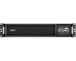
Front Panel Features

- Display interface panel
- UPS battery connectors
- Battery module
- Bezel
Rear Panel Features
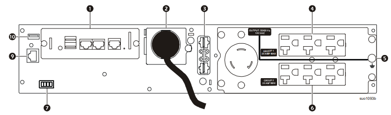
Note: Refer to the table “Key to identify rear panel features” on page 8, that provides a key to the callout numbers for the rear panel graphics depicted in this manual
SRT2200XLA/SRT2200RMXLA

SRT2200RMXLA-NC
SRT3000XLA/SRT3000RMXLA

SRT3000RMXLA-NC

Key to identify rear panel features
- SmartSlot: The SmartSlot can be used to connect optional management accessories.
- AC input power cable or hardwire input box: All models have factory installed input power cables. Hardwired input box is an optional accessory.
- External battery power and communication connector: Use the external battery cable on the XLBP to connect the UPS and XLBP. XLBPs provide extended runtime during power outages. The UPS will automatically recognize up to 10 external battery packs.
- Controllable outlet group 1: Connect electronic devices to these outlets.
- Chassis ground screw: The UPS and XLBPs have ground screws for connecting the ground leads. Prior to connecting a ground lead, disconnect the UPS from mains power.
- Controllable outlet group 2: Connect electronic devices to these outlets.
- EPO terminal: The Emergency Power Off (EPO) terminal allows the user to connect the UPS to a central EPO system.
- Serial Com: The Serial Com port is used to communicate with the UPS. Use only interface kits supplied or approved by APC by Schneider Electric. Any other serial interface cable will be incompatible with the UPS connector.
- USB port: The USB port is used to connect either a server for native operating system communications, or for software to communicate with the UPS. Note: Serial and USB communication should not be used simultaneously. Use either the Serial Com or the USB port.
- Main outlet: Connect electronic devices to the main outlet.
Operation
Connect Equipment
Note: The UPS batteries will charge to 90% capacity in the first three hours of normal operation. Do not expect full battery runtime capability during this initial charge period.
- Connect the internal battery module. See Installation manual for details.
- Connect equipment to the outlets on the rear panel of the UPS. Refer to “Controllable Outlet Groups”.
- Connect the UPS to the building utility power.
Turn the UPS On/Off
The first time the UPS is turned on the Setup Wizard screen will run. Follow the prompts to configure UPS settings. Refer to “Configuration”.
To turn on the UPS and all connected equipment, press the POWER ON/OFF button on the display panel. Follow the prompts to either turn the UPS on immediately or after a delay, then press OK. NOTE: When there is no input power and the UPS is off, the cold start feature can be used to turn on the UPS and connected equipment using battery power.
To perform a cold start press the POWER ON/OFF button. The display panel will illuminate and the POWER ON/OFF button will illuminate red. To turn on the output power press the POWER ON/OFF button again. Select the prompt Turn ON with NO AC and press OK.
To turn output power off, press the POWER ON/OFF button. Follow the prompts to either turn the UPS off immediately or after a delay, then press OK. NOTE: Once the UPS output power has been turned off and the AC input has been removed, the UPS will continue to use the battery for internal power for 10 minutes. To remove power completely press the POWER ON/OFF button. Follow the prompt to select Internal Power Off, then press OK.
UPS Display Interface

- POWER ON/OFF button - Button illumination indications: No illumination, the UPS and the output power are off; White illumination, the UPS and the output power are on; Red illumination, the UPS is on and the output power is off
- Load icon; Disable/mute audible alarm icon
- PS status information
- Operation mode icons
- ESCAPE button
- OK button
- UP/DOWN buttons
- Controllable outlet group status icons
- Battery status icons
LCD display interface angle adjustment
The angle of the LCD display interface can be adjusted for ease in viewing the displayed messages.
- Remove the front bezel.
- Locate the button on the bottom of the display interface panel.
- Press the button and slide the bottom of the LCD display interface screen out. An audible click will be heard when the screen reaches the maximum angle.
Menu overview
The UPS Display Interface has Standard and Advanced menu screens. The preference for Standard or Advanced menu selections is made during initial installation and can be changed at any time through the Configuration menu.
The Standard menus include the most commonly used options.
The Advanced menus provide additional options.
Note: Actual menu screens may differ by model and firmware version
Configuration
UPS Settings
There are four ways to select UPS configuration options.
- The first time the UPS is turned on the Setup Wizard screen will open. On each menu screen select the desired settings. Press OK after each UPS setting is selected. Note: The UPS will not turn on until all of the settings have been configured.
- Main Menu/Configuration/UPS/Default Setting. This screen allows the user to reset the UPS to factory default settings. Press OK after the UPS setting is selected. Refer to “Configuration” on page 13 and “UPS Menu Overview” .
- Configure settings using an external interface, such as the Network Management Web interface.
Controllable Outlet Groups
Overview
The controllable outlet groups can be configured using the Advanced menu options. Refer to “General settings”. The controllable outlet groups can be configured to independently turn off, turn on, shutdown, switch to sleep mode, and reboot connected equipment.
- Turn Off: Disconnect output power to connected equipment either immediately using the Turn Off Immediately feature or after a configured delay using the Turn Off With Delay feature. NOTE: Controllable outlet groups can be turned on only using the Turn On feature.
- Turn On: Connect output power to connected equipment either immediately using the Turn On Immediately feature or after a configured delay using the Turn On With Delay feature.
- Shutdown: Disconnects the power to connected equipment either immediately or after a configured delay. Equipment reconnects after a configured delay when mains power becomes available and other configured conditions are met. Each controllable outlet group can be configured separately to allow power sequencing for equipment connected to any controllable outlet group.
- Reboot: Disconnect the power to connected equipment either immediately or after a configured delay. Reconnect equipment after a configured delay when either mains or battery power becomes available and other configured conditions are met. Each controllable outlet group can be configured separately to allow power sequencing for loads connected to any controllable outlet group.
- Sleep: This mode is a reboot with an extended duration where a outlet(s) remain turned off. Disconnect the power to connected equipment either immediately or after a configured delay. Reconnect equipment after a configured delay when either mains or battery power becomes available and other configured conditions are met. Each controllable outlet group can be configured separately to allow power sequencing for equipment connected to any controllable outlet group. To configure Sleep mode use an external interface, such as the Network Management Web interface.
- Automatically turn off or shutdown when certain conditions occur, based on user configurations set using the Config Menu Outlets menus. Refer to “Configuration”.
Connect controllable outlet groups
- Connect critical equipment to one controllable outlet group.
- Connect peripheral equipment to the other controllable outlet groups.
- To conserve battery runtime during a power outage, nonessential equipment can be configured to shut down. Use Loadshed Time on Battery Enable/Disable and Loadshed Time on Battery Setting defined in the General Settings section. Refer to “General settings”.
- If equipment has dependent peripherals that must restart or shut down in a specific sequence, such as an ethernet switch that must restart before a connected server can be restarted, connect the devices to different outlet groups. Each controllable outlet group can be configured independently of the other groups.
- Use the Configuration menus to configure how the controllable outlet groups will react in the event of a power outage.
Emergency Power Off
Overview
The Emergency Power Off (EPO) option is a feature that will immediately disconnect all connected equipment from mains power.
The UPS will immediately shut down and will not switch to battery power. Connect each UPS to the EPO switch. If multiple units are to be controlled with an EPO switch, each UPS must be connected separately to the EPO switch. The UPS must be restarted for power to return to connected equipment. Press the ON/OFF button on the front panel of the UPS.
Normally open contacts

- If the EPO switch or relay contacts are normally open, insert the wires from the switch or contacts at pins 1 and 2 of the EPO terminal block. Use 16-28 AWG wire.
- Secure the wires by tightening the screws. If the contacts are closed, the UPS will turn OFF and power will be removed from the load.
Normally closed contacts

- If the EPO switch or relay contacts are normally closed, insert the wires from the switch or contacts at pins 2 and 3 of the EPO terminal block. Use 16-28 AWG wire.
- Insert a wire jumper between pins 1 and 2. Secure the wires by tightening the three screws at positions 1, 2, and 3. If the contacts are opened, the UPS will turn OFF and power will be removed from the load.
Note: Pin 1 is the power source for the EPO circuit, it provides a few milliampere of 24 V power.
If the normally closed (NC) EPO configuration is used, the EPO switch or relay should be rated for “dry” circuit applications, the rating should be for low voltage and low current applications. This normally implies the contacts are gold plated.
The EPO interface is a Safety Extra Low Voltage (SELV) circuit. Connect the EPO interface only to other SELV circuits. The EPO interface monitors circuits that have no determined voltage potential. SELV circuits are controlled by a switch or relay properly isolated from mains power. To avoid damage to the UPS, do not connect the EPO interface to any circuit other than a SELV circuit.
Use one of the following cable types to connect the UPS to the EPO switch.
- CL2: Class 2 cable for general use.
- CL2P: Plenum cable for use in ducts, plenums, and other spaces used for environmental air.
- CL2R: Riser cable for use in a vertical run in a floor to floor shaft.
- CLEX: Limited use cable for use in dwellings and for use in raceways.
- Installation in Canada: Use only CSA certified, type ELC, (extra low voltage control cable).
- Installation in countries other than Canada and the USA: Use standard low voltage cable in accordance with national and local regulations.
Network Management Interface (For NC models only)
Introduction
The UPS has a network port and console port that can be used to access the Network Management Interface. Refer to the Network Management Card utility CD supplied with this product.
IP Address Configuration
The default TCP/IP configuration setting DHCP, assumes that a properly configured DHCP server is available to provide TCP/IP settings to the Network Management Interface.
If the Network Management Interface obtains an IPv4 address from a DHCP server, use the display interface menus About/Accessory, to see the address.
To setup a static IPv4 address use the display interface Config menu. Set the IP address Subnet Mask and Gateway from the Config menu.
See the User’s Guide on the Network Management Card Utility CD for user information about the Network Management Interface and for setup instructions.
Related Documents
The Network Management Card Utility CD contains the following documentation:
- UPS Network Management Card 2 User’s Guide
- Network Management Card Upgrade Utilities
- Security Handbook
- PowerNet Management Information Base (MIB) Reference Guide
Smart Battery Management
Definitions
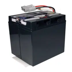
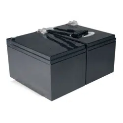
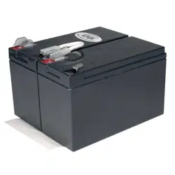
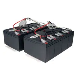
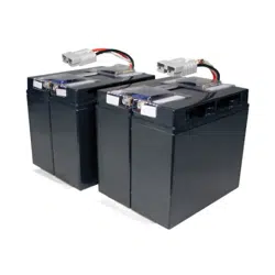
- Battery Module: A string of battery cells arranged to produce a battery assembly with a connector. • Replaceable Battery Cartridge (RBC): An APC battery cartridge consisting of one battery module. Replacement RBCs can be ordered from the APC by Schneider Electric web site, www.apc.com.
- Smart External Battery Pack (XLBP): An enclosure that contains RBC(s) and battery management electronics.
- User Interface (UI): Any interface by which a user can interact with the system. This may include a UPS display interface, a network management interface or PowerChute™ Network Shutdown software.
NOTE: Do not use a battery that is not APC approved. The system will not detect the presence of a non APC approved battery and may adversely affect the operation of the system. Use of a non APC approved battery will void the manufacturer warranty
Features
Smart Battery Management provides the following features:
- Monitors and informs the user of the health of each RBC.
- Monitors and shows on the UPS Display Interface screen, the date for the end of useful life for each RBC.
- The UPS emits an audible alarm and shows a message on the UPS Display Interface screen to indicate the estimated battery end of life. On the UPS Display Interface screen the user can set the number of days before the audible alarm is heard and the message appears on the UPS Display Interface screen.
- Automatically detects the addition or removal of XLBPs and RBCs.
- Monitors the internal temperature of each XLBP and automatically adjusts the battery charging.
Maintenance
- RBC maintenance: The APC RBC uses sealed, maintenance-free, Valve Regulated Lead-Acid batteries and does not require maintenance.
- Runtime Test (Calibration): This should be performed anytime the steady state load is changed significantly, for example a new server is added to or removed from the UPS load.
- Battery health monitoring: The battery energy output and voltage are monitored to assess the health of the installed batteries when the UPS is operating on battery.
- Battery health monitoring is done during a UPS Self Test, a Runtime Calibration Test, and when the UPS is operating on battery power.
- The UPS can be configured to perform periodic, automatic Self Tests.
End of useful life
- Near end of life notification: A message will appear on the UPS display interface screen when each RBC is approaching the end of its useful life. For configuration details refer to Replacement Notification Time and Replacement Battery Alarm Time.
- The estimated replacement date for each RBC is available through the UI.
- Needs replacement notification: The UPS display interface screen shows when RBC replacement is required. The RBC must be replaced as soon as possible. When an RBC requires replacement, the UPS display interface may recommend that additional RBCs be replaced if they will soon reach the end of their useful life.
- Recycling: Remove the RBC from the XLBP. Recycle the RBC. Do not disassemble an RBC.
Replace the RBC in a UPS
An RBC should only be disconnected or removed from the UPS temporarily as part of the battery replacement procedure.
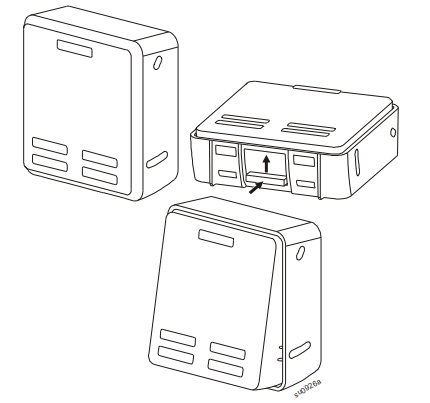
- Disconnect the connected battery module in the UPS. Slide the RBC out of the UPS.
- Slide the new RBC into the UPS and connect the battery module to the UPS.
- Securely connect the battery module. Press the battery connector into the UPS until it is firmly connected. A battery that is not properly connected will cause erratic UPS operation, abnormal alert messages and connected equipment may not receive battery power during power outages.
- After installing the RBC, the UPS display interface may prompt the user to verify the status of the replaced battery module. If the battery module is new, respond YES. If the battery module is not new, respond NO.
Recommended actions after installing new RBC
- Verify that the UPS is connected to input power and the output power is turned on.
- Verify on the UPS display interface that the installation dates for the replaced RBC is set to the current date. The installation dates can be changed manually on the UPS display interface. For configuration details refer to Battery Install Date in the “General settings” on page 14 of this manual.
- Allow the system to charge for 24 hours to ensure full runtime capability
XLBP installation and replacement
- Refer to the External Battery Pack Installation Guide for installation and replacement instructions.
Troubleshooting
UPS is not turning on or there is no output
- The UPS is not connected to mains power: Be sure the power cable is securely connected to the mains power supply
- The UPS display interface screen shows very low or no mains power: Check the mains power supply to verify acceptable power quality
- There is an internal UPS alert or message: The UPS Display Interface screen will show a message to identify the alert or message and corrective action.
UPS emits an audible alarm
- Normal UPS operation when running on battery power: The UPS is operating on battery power. Refer to the status of the UPS as shown on the UPS Display Interface screen. Press any key to mute all audible alarms.
- The UPS emits an audible alarm and has a red or amber back light on the UPS Display Interface screen: The UPS has detected a fault. Refer to the display interface screen for information.
UPS does not provide expected backup time
- The UPS batteries are weak due to a recent power outage or they are near the end of service life: Charge the batteries. Batteries require recharging after extended outages and wear out faster when put into service often or when operated at elevated temperatures. If the batteries are near the end of service life, consider replacing the batteries even if the Replace Battery message is not displayed.
- The UPS is experiencing an overload condition:
- The connected equipment exceeds the specified maximum load. Refer to the APC by Schneider Electric web site, www.apc.com for product specifications.
- The UPS will emit a sustained audible alarm until the overload condition is corrected.
- Disconnect nonessential equipment from the UPS to correct the overload condition.
UPS operates on battery power while connected to mains power
- The input circuit breaker has tripped: Reduce the load on the UPS. Disconnect nonessential equipment and reset the circuit breaker. Check the circuit breaker rating for the connected equipment.
- There is very high, very low, or distorted input line voltage:
- Navigate to the UPS Display Interface screen that shows input voltage. Verify that the input voltage is within specified operating limits.
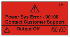
- If no input voltage is indicated on the UPS Display Interface screen, contact Customer Support through the APC by Schneider Electric web site, www.apc.com.
- The UPS Display Interface screen shows the message Waiting for Minimum Runtime: The UPS has been configured to operate for a specified period of runtime. The setting can be changed through the Config/UPS menus.
UPS Display Interface Status screen shows Overload and the UPS emits a sustained audible alarm
- The UPS is experiencing an overload condition
- The connected equipment exceeds the maximum load rating for the UPS.
- The UPS will emit a sustained audible alarm until the overload condition is corrected.
- Disconnect nonessential equipment from the UPS to correct the overload condition.
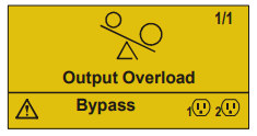
UPS Display Interface Status screen shows UPS is operating in Bypass mode
- The UPS received a command to operate in Bypass mode: No action is required.
- The UPS has automatically switched to Bypass mode due to an internal UPS alert or message: The UPS Display Interface screen will show a message to identify the alert or detected error and corrective action.
UPS Display Interface is red or amber and shows an alert or message. The UPS emits a sustained audible alarm
- The UPS has detected a problem during normal operation: Follow the instructions on the UPS Display Interface screen. Press any key to mute all audible alarms.
- The UPS Display Interface screen shows the message Disconnected Battery: Be sure the battery cables are securely connected. Perform a UPS Self Test to be sure the UPS detects all connected batteries. To perform a UPS Self Test use the UPS Display Interface menu option Test and Diagnostics.
- The UPS Display Interface screen shows the message Replace Battery: Replace all of the batteries. Contact APC by Schneider Electric customer support.
The UPS display turns red or amber, displays an alert message, and emits a sustained audible alarm. Red illumination indicates a UPS alarm that requires immediate attention. Amber illumination indicates a UPS alarm that requires attention.
- There is an internal UPS alert or message.
- Do not attempt to use the UPS. Turn the UPS off and have it serviced immediately
- The UPS is experiencing an overload condition.
- Reduce the load on the UPS. Disconnect nonessential equipment.
- The UPS has detected a Site Wiring Fault.
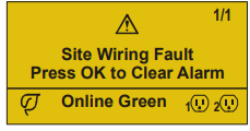
- Correct the building site wiring fault or ignore this message. See Config Menu UPS in “General settings”.
The Replace Battery alert is displayed
- The battery has a weak charge: Allow the battery to recharge for at least four hours. Then, perform a UPS Self Test. If the problem persists after recharging, replace the battery.
- The replacement battery is not properly connected: Be sure the battery cable is securely connected.
Transport
- Shut down and disconnect all connected equipment.
- Disconnect the unit from mains power.
- Disconnect all internal and external batteries (if applicable).
- Follow the shipping instructions outlined in the Service section of this manual.
Service
If the unit requires service, do not return it to the dealer. Follow these steps:
1. Review the Troubleshooting section of the manual to eliminate common problems.
2. If the problem persists, contact APC by Schneider Electric Customer Support through the APC by Schneider Electric web site, www.apc.com.
a. Note the model number and serial number and the date of purchase. The model and serial numbers are located on the rear panel of the unit and are available through the LCD display on select models.
b. Call Customer Support. A technician will attempt to solve the problem over the phone. If this is not possible, the technician will issue a Returned Material Authorization Number (RMA#).
c. If the unit is under warranty, the repairs are free.
d. Service procedures and returns may vary internationally. For country specific instructions refer to the APC by Schneider Electric web site, www.apc.com.
3. Pack the unit properly to avoid damage in transit. Never use foam beads for packaging. Damage sustained in transit is not covered under warranty. Note: Before shipping, always disconnect battery modules in a UPS or external battery pack. The disconnected internal batteries may remain inside the UPS or external battery pack.
4. Write the RMA# provided by Customer Support on the outside of the package.
5. Return the unit by insured, prepaid carrier to the address provided by Customer Support.