Loading ...
Loading ...
Loading ...
As the colours of the wires in the mains lead may not
correspond with the coloured markings in your plug, proceed
as follows:
Connect the BROWN wire to the terminal marked ‘L’ or
coloured RED. Connect the BLUE wire to the terminal
marked ‘N’ or coloured BLACK. Note: ‘L’ or ‘N’ must not
be connected to the EARTH terminal marked ‘E’ or ‘ ’ or
coloured GREEN or GREEN AND YELLOW.
If in doubt, consult your electrician.
Installation
The different parts of this appliance used to assemble and mount
this product are identied in Fig. 3. They are the Clamping Knob
- (W), the Saddle - (X), the Foot - (Y) and the Tilt base - (Z).
Note: When mounting the product on its foot for portable use it must
not be mounted vertically as shown in Fig. 2. The product is tted
with a safety tilt switch which will prevent it from operating should
the heater be tilted more than 45
o
from horizontal.
Portable Use - see Fig. 1 & Fig. 3
WARNING: The heater should never be used as a portable
appliance without the foot securely tted.
1. Set the foot (Y) on the ground.
2. Remove both clamping knobs (W) and saddles (X) from the
main heater body by unscrewing the clamping knob (W).
3. Lift the heater, holding it level and horizontal, and line up the
right tilt base (Z) with the corresponding hole in the foot (Y).
4. Line up the clamping knob (W) and saddle (X) with the foot
(Y) and tilt base (Z) and screw the clamping knob (W) into
position until it is tight.
5. Complete the same for the left hand side of the heater.
6. Ensure the heater is stood on a rm level base near to but not
directly beneath a suitable mains supply socket.
7. Maintain the clearances as shown in Fig. 1 to the back and
sides of the heater.
Adjusting the tilt - see Fig. 4
Once the heater is mounted on the foot, the tilt of the heater can
easily be adjusted. Loosen the Clamping knobs on the heater
slightly but do not unscrew completely.
The heater will tilt up 30 degrees from horizontal when portable
as shown in Fig. 4.
Using the Heater
Main Elements - See Fig 5
- Thermostat Knob
- Switch Knob
- Neon
Heat Control - see Fig. 5
- Off
- Cool Blow*
- Half Heat
- Full Heat
Thermostat Control - see Fig. 5
The heat output is controlled by the thermostat, according to the
room temperature.
Turn the thermostat knob fully clockwise to maximum setting
initially. When the room is warm enough, reduce the setting slowly
until the heater just clicks off.
The heater will now cycle on and off to maintain your selected room
temperature. An audible click may be heard when the thermostat
operates - this is normal.
Note: If the heater does not come on when the thermostat is at a
low setting, this is normally because the room is warmer than the
thermostat setting and is not a fault.
* When the heat control is set to ‘ ’ for cool blow, set the
thermostat control to maximum.
Position ‘ ’ will turn the heater on and off to maintain a temperature
of approximately 5°C.
Safety - overheat protection
For your safety this appliance is tted with a thermal cut-out. In
the event that the product overheats for some reason, the cut-out
prevents excessive temperatures on the product by cutting the
power to the heater. Once the heater has cooled down, it will reset
automatically, it will continue to cycle on and off automatically until
the reason for overheating is removed.
Fuselink
A thermal fuse link is provided as an added safety feature. If the
fuse link operates and opens circuit it is the result of abnormal
overheating within the appliance and servicing of the appliance by
a competent service engineer will be required in order to ensure
the future safe operation of the heater. Customer services should
be contacted in the event of fault or failure.
Cleaning
WARNING ALWAYS DISCONNECT FROM THE POWER
SUPPLY BEFORE CLEANING THE HEATER.
Do not use detergents, abrasive cleaning powders or polish of
any kind on the heater. Wipe with a dry cloth to remove dust and
a damp cloth (not wet) to clean off stains. Be careful not to allow
moisture into the heater.
Ensure that dust or uff does not accumulate inside the heater
as this could lead to overheating of the element. Use a vacuum
cleaner to remove any uff which does accumulate.
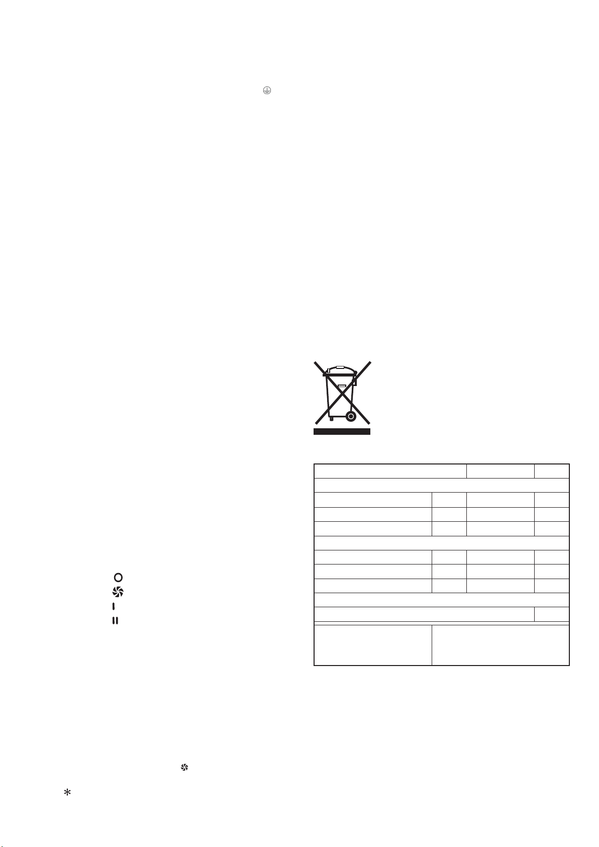
Recycling
For electrical products sold within the European
Community.
At the end of the electrical products useful life it
should not be disposed of with household waste.
Please recycle where facilities exist. Check with
your Local Authority or retailer for recycling advice
in your country.
Model Identier(s):
DXTT3
Heat output
Nominal heat output Pnom 3.0
kW
Minimum heat output (indicative) Pmin 1.8
kW
Maximum continuous heat output Pmax,c 3.0
kW
Auxiliary electricity Consumption
At nominal heat output elmax 0.0
kW
At minimum heat output elmin 0.0
kW
In standby mode elSB 0.0
kW
Type of heat output/ room temperature control
Mechanical thermostat room temperature control
Yes
Contact details
GDHV
Millbrook House, Grange Drive,
Hedge End, Southampton.
SO30 2DF
Loading ...
Loading ...
Loading ...