This thermostat can be used with most 24 volt: gas, oil, Millivolt, electric heating and cooling
systems, including heat pumps with an aux/emerg heat element.
It cannot be used with: 120/240 volt heating elements (without a transformer), or on heat pumps
that have two compressor stages (Y2). Ask your dealer for other LUX thermostats to control those
systems.
• The thermostat requires batteries to operate and failure or sub-standard performance of the
batteries may impair or prevent the correct operation of the thermostat. Use Duracell
®
or
Energizer
®
alkaline batteries ONLY for all LUX thermostats requiring batteries. BE SURE TO
CHANGE THE BATTERIES AT LEAST ONCE A YEAR, or whenever you see the LO BATT indication
on the screen. Failure to follow these battery instructions could result in property damage
and/or personal injury.
• The electrical rating for this thermostat is 1.5 Amps per terminal, with a maximum total load of
3.0A for all terminals combined.
• The thermostat contains parts that may wear out through use and are susceptible to failure if
over-loaded or used in a manner other than as indicated in the documentation.
• Check unoccupied residences regularly to ensure that all systems are operating properly.
• Check any heating/air-conditioning system including this product before operation and at
regular intervals.
• Electrical interference, static electricity, failure or substandard performance of batteries, wiring
defects in the installation and/or characteristics of the connected HVAC devices may prevent
the system from regulating heating and cooling as anticipated.
• The thermostat is a sensitive device and dropping the product can cause damage to critical
components. If the product is dropped or shaken violently during transport or installation then it
should be replaced immediately.
• Persons with physical or mental limitations may not be able to promptly respond to a
malfunction of the heating/air-conditioning system.
• All residents should be made aware of the potential in any system for malfunctions that could
cause continuous heating or cooling and should be familiar with the operation and location of
the heating/cooling appliance on/off switch.
• Read the instruction manual completely before installing the thermostat. A more detailed
product manual is available on our www.luxproducts.com website. You should consult a
qualified HVAC technician or an electrician if you do not fully understand the installation
instructions.
1. Turn OFF the electricity to all heating and cooling components. Do not turn the electricity back
on until all work is completed.
2. Write down the letters printed near each wire terminal that is used, and also the color of each
wire that is connected to it. Self-adhesive wire labels are also enclosed.
3. Carefully remove the wires one at a time, and bend them in a manner so that they do not fall
back inside the wall. Do not allow bare wire ends to touch each other.
Use the wiring diagrams shown on the back of this installation sheet to find the closest match to
your particular heating and/or cooling system. Please read ALL of the Wiring Diagram Notes that
are shown above the connection diagrams, to avoid causing damage to your system or the new
thermostat.
1. Strip wire insulation leaving only 3/8 in. (9.5mm) bare wire ends, and clean off any corrosion
present.
2. Fill the wall opening with non-combustible insulation to prevent drafts from affecting the
thermostat’s normal operation.
3. Route the wires through the opening in the new thermostat base plate, and install the mounting
screws.
4. If the previous holes cannot be used, hold the thermostat base against the wall so that it
appears straight and level (position the base for best appearance) and mark for the new screw
holes. Attach the base to the wall using the screws provided (use the supplied plastic anchors
if needed when mounting to a soft material such as drywall).
5. When attaching the wires to the thermostat, please ensure that the bare wire ends are held ALL
the way into the terminal block while the screw is being tightened, and be careful not to over
tighten them, as they only need to be snug.
HEAT / OFF / COOL, SYSTEM MODE SWITCH: Set this switch to HEAT to control your heating
system, and COOL to control your cooling system. The OFF position will disable both the heating
and cooling units.
AUTO / ON, FAN MODE SWITCH: When this switch is in AUTO, the blower fan (if present in your
system) will automatically cycle on and off by itself while heating or cooling is running. When in
the ON position, the blower fan will run constantly with or without a demand for heating or
cooling, even when the System Mode switch is in the OFF position.
NOTE: The Fan Mode switch only works if your system provides a wire for the thermostat’s “G”
wire terminal, to control a blower fan. The Fan Mode switch has no effect in systems that do not
have a blower fan (such as a hot water radiator system).
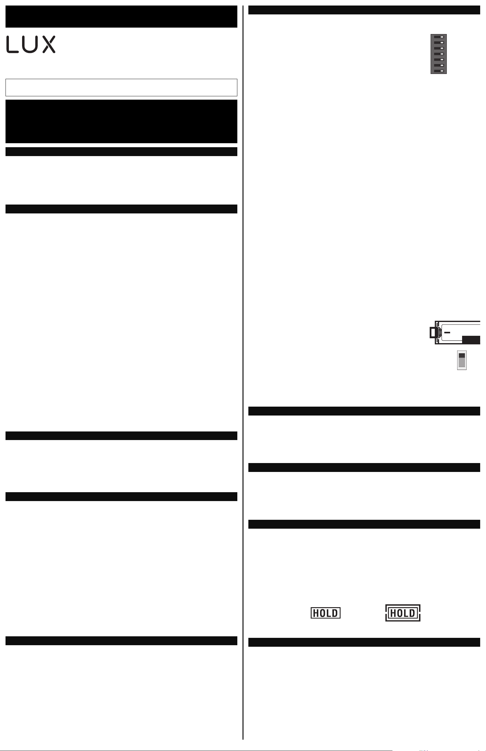
On the thermostat’s circuit board, there is a row of DIP switches,
labeled #1 through #7. The position of these switches will change
how the thermostat operates, and also how information is conveyed
to you on the LCD display screen. If you make any changes to
these options, the changes are not recognized unless you either:
change the position of the HEAT/OFF/COOL mode switch, or press
the “HW RST” (Hardware Reset) button on the circuit board.
These option switches are very small and should be moved carefully
using objects such as: eyeglass screwdriver, fine-point pen,
toothpick, or similar. The listing below describes the available
choices for each option switch:
SWITCH #1 (SYSTEM): [OFF/RIGHT = FURN, default] This is for the majority of heating systems
that are not Heat Pumps, such as a gas furnace or hot water boiler. [ON/LEFT = H/P] Use this
setting if you have a Heat Pump system, which uses the outdoor unit as the primary heat source
and may also contain an electric heating element as a backup heat source. When set to “HP”,
ensure that you have also set the Gas/Elec option to “ELEC”.
SWITCH #2 (THERMOSTAT TYPE): [OFF/RIGHT = PROG, default] Use this setting for following a
daily program routine. [ON/LEFT = MAN] This setting omits the program routine and operates as
a manual style non-programmable thermostat. This is very basic and only shows the room
temperature and set temperature on the screen, with no clock.
SWITCH #3 (PERIOD QUANTITY): [OFF/RIGHT = 4, default] Thermostat uses four periods per day
(called MORN, DAY, EVE, and NITE). [ON/LEFT = 2] The thermostat uses two periods per day
(called DAY and NITE).
SWITCH #4 (TEMPERATURE SCALE): [OFF/RIGHT = F, default] Shows all temperature values in
Fahrenheit. [ON/LEFT = C] Shows all temperature values Celsius.
SWITCH #5 (CLOCK FORMAT): [OFF/RIGHT = 12Hr, default] This displays the clock times using
standard AM and PM values. [ON/LEFT = 24Hr] This displays the clock times using the military-
time format (example 22:00 hours, without using AM or PM).
SWITCH #6 (DELAY TIME): [OFF/RIGHT = 5, default] Thermostat waits 5 minutes before turning
the system back on after it was last run. This internal delay prevents rapid cycling and provides
equipment protection. The 5 minute setting is fine for most applications. [ON/LEFT = 2] Same
operation as above but reduced to 2 minutes between state changes.
SWITCH #7 (EARLY RECOVERY): [OFF/RIGHT = OFF, default] Program Set Temperature values
start to occur at exactly the period start times. [ON/LEFT = ON] Early Recovery affects how the
transition occurs when changing from the NITE to the MORN period, and when changing from the
DAY to the EVE period. The thermostat calculates how long it takes for your home to recover from
a setback on a daily basis, and turns on ahead of time in order to reach the target set point of the
next upcoming program period by the period’s start time. While in a recovery, the words “IN
RECOV” will be shown on the display screen.
GAS / ELEC SLIDE SWITCH (FAN OPERATION):
This switch is a physical component by itself on the circuit board,
and is much larger than the DIP switches listed above.
[UP = GAS, default] This setting lets the heating system control
the blower fan automatically by itself. Systems that would
typically use the “GAS” setting would be: natural gas, propane, or
oil furnaces. This setting has no effect upon Cool mode
operation. [DOWN = ELEC/HP] This setting runs the system’s
blower fan when heat is called for, and is required for heating
systems that do not control their own fan while the thermostat is
in HEAT mode. Heat pump systems, and units with an electric
heating element typically require this setting.
NOTE: If your blower fan does not operate properly after installation, try moving the Gas / Electric
option to the “Electric” setting.
Once the hardware options are set, install two new Energizer
®
or DURACELL
®
"AA" size alkaline
batteries. Ensure that the batteries are installed in the proper direction as per the markings
shown in the battery tray. If the batteries were already installed before changing the hardware
setup options, change the position of the HEAT/OFF/COOL System Mode switch to accept the new
hardware option switch settings.
Press the MENU button. The first menu item shown is “SET DAY/TIME”, press the OK button.
With the day flashing, press UP or DOWN to set the day of the week. Press NEXT and the clock
time will start flashing. Use UP or DOWN to set the time, making sure the AM/PM indication is
correct. Holding the UP or DOWN buttons will make the clock digits scroll rapidly. Press the EXIT
button to return to the Normal Run screen.
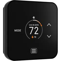
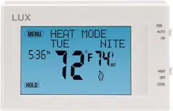
Basic operation of your heating or cooling system can be obtained by choosing either HEAT or
COOL on the System Mode switch. Touch the Set Temperature digits on the screen and they will
begin to flash. While they are flashing, the UP and DOWN buttons will be shown also, which you
can use to adjust the current Set Temperature. When the thermostat is first powered up, it will
follow a default temperature routine that is preset from the factory.
Alternatively, you can use the HOLD button to maintain a fixed Set Temperature. The HOLD button
is in the lower left corner, when in either Heat or Cool operating modes. The visual appearance of
the HOLD button will change depending upon whether or not it is currently active.
This sheet contains basic installation steps and setup instructions. There are additional topics
covered in greater detail, such as adjustable set temperature limits, keypad lockout, and the air
filter monitor, in the full version of the instruction manual for this thermostat product. The full
PDF version of this manual can be downloaded at http://www.luxproducts.com. Click on
SUPPORT, then INSTRUCTION MANUALS.
TX9600TSa 7-Day Universal
Touchscreen Thermostat
(Programmable or Non-Programmable)
53521-15
WARNING: Use Energizer
®
or DURACELL
®
Alkaline Batteries Only.
Energizer
®
is a registered trademark of Eveready Battery Company, Inc.
DURACELL
®
is a registered trademark of The Procter & Gamble Company
Lux Products Corporation - www.luxproducts.com
PRODUCT INSTALLATION MANUAL
REMOVAL OF OLD THERMOSTAT:
CAUTIONS AND WARNINGS:
SYSTEM COMPATIBILITY:
INSTALLATION OF NEW THERMOSTAT:
SET DAY AND TIME:
COMPLETE THE INSTALL:
SYSTEM CONFIGURATION AND SETUP OPTIONS:
FRONT PANEL ITEMS:
© 2015 LUX PRODUCTS CORPORATION. ALL RIGHTS RESERVED
IMPORTANT!
• Label every wire terminal designation on your existing thermostat wiring before removing
your old thermostat.
• Ignore the color of the wires since they may not comply with any standard. Please
connect wires using the terminal letter designations.
BASIC HEATING AND COOLING OPERATION:
ON
1234567
1
7
GAS
ELEC
BATTERY
HOLD
BUTTON
“OFF”
HOLD
BUTTON
“ON”
DOWNLOAD FULL INSTRUCTION MANUAL FROM OUR WEBSITE:
This is a 7-day thermostat, which means that all 7 days of the week can be programmed separately.
By default, this thermostat has 4 separate program periods for both Heat and Cool modes, they are:
MORN, DAY, EVE, and NITE. Each period ends at the start time of the next upcoming period. The Heat
temperature programs are set while the mode switch is in the HEAT position, and the Cool temperature
programs are set while the mode switch is in the COOL.
NOTE: If the thermostat is configured to use only 2 periods per day (instead of the factory default of 4
periods per day), the thermostat will only use the DAY and NITE period designations. The MORN and
EVE periods will not be used or visible on the screen.
TO SET A TEMPERATURE PROGRAM: Press the MENU button, then press the SCROLL button until
“SET/REVIEW HEAT PROGMS” is shown, then press the OK button to enter the programming screen. Use
the UP and DOWN buttons to adjust the start time for the MORN period, then press the NEXT button to
advance. Use the UP and DOWN buttons to adjust the set temperature for the MORN period, then press
the NEXT button to advance. Now adjust the start time and set temperature for the DAY period,
pressing the NEXT button after each to advance. Continue with these same steps to adjust the start
times and set temperatures for the EVE and NITE program periods.
When the NITE period is finished the thermostat will advance to Tuesday, with the MORN period start
time flashing. Perform the same steps that you used for setting the Monday periods, pressing the NEXT
button to advance through each flashing value. Press the EXIT button to return to the Normal Run
screen.
Emergency Heat mode is only present if the thermostat is setup for a Heat Pump configuration (SETUP
OPTION SWITCH #1 set to “HP”). While in normal Heat mode, one single press of the EMER button will
activate Emergency Heat mode. While in Emergency Heat, the top of the screen will change from “Heat
Mode” to show “Emer Heat”. A single press of the EMER button again will end Emergency Heat, and
return back to normal Heat mode. If a power loss occurs while in Emergency Heat mode, the
thermostat will continue to remain in Emergency Heat mode even after the power comes back on.
Emergency Heat mode will prevent the first stage of your heat pump system from turning on, and use
only the “W2” heat terminal (Auxiliary Heat) as the primary heating source. This will not only prevent
the heat pump from wasting energy if outdoor temperatures are too low to support efficient operation,
but it could also prevent damage to the heat pump if outside temperatures are below the
manufacturer’s recommendations. As every heat pump has different operating characteristics, you
should refer to your heat pump literature to determine when to disable the heat pump and run in
Emergency Heat mode. In general for most heat pump systems, use Emergency Heat mode whenever
the outside temperature is less than 32F degrees.
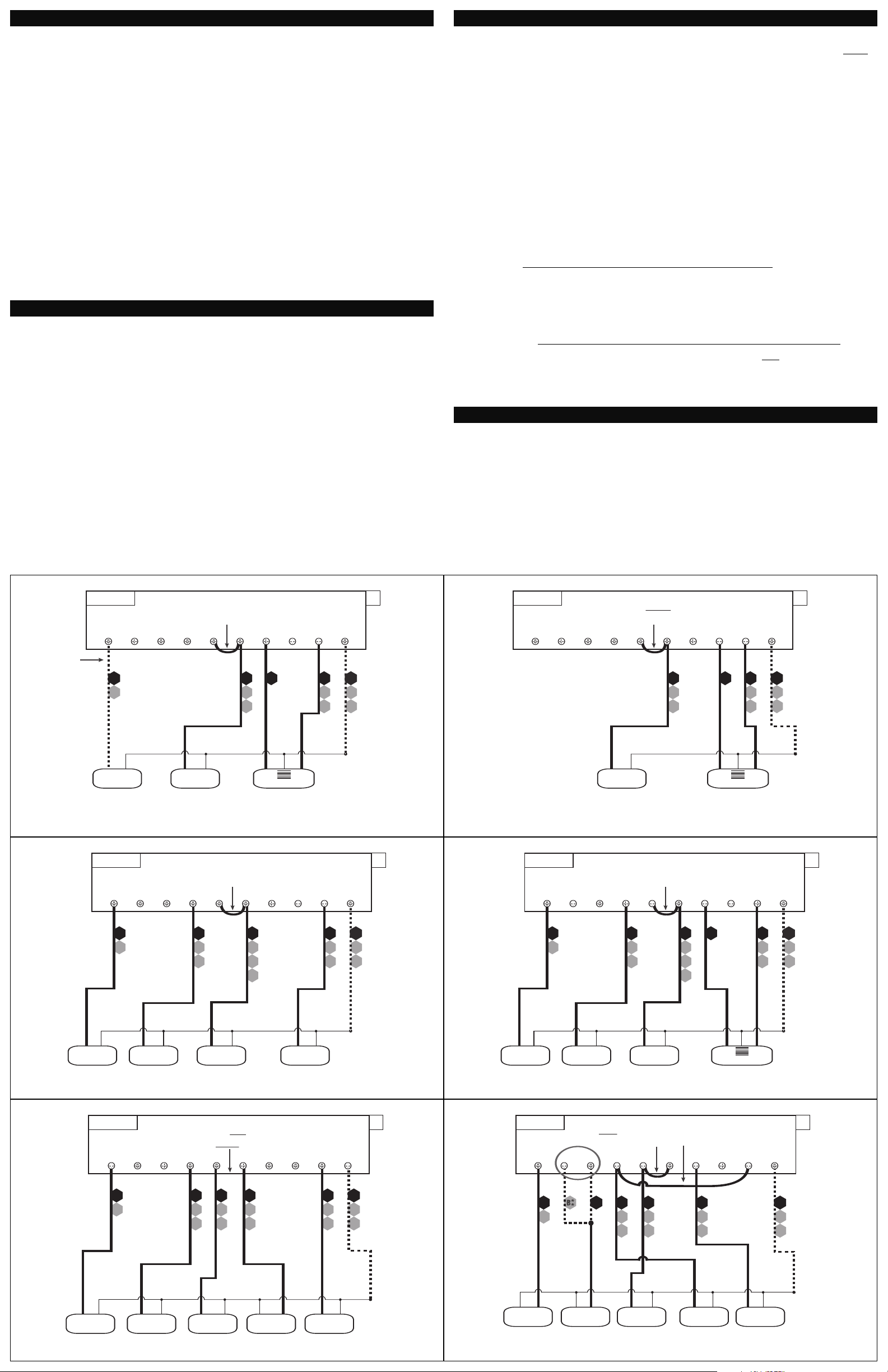
• If the information provided in the following wiring diagrams does not clearly represent or match your
system, please refer to the “TECHNICAL ASSISTANCE” section of this manual, and contact us before
removing any of your existing thermostat wiring.
• All of the dashed wires shown in the wiring diagrams are either optional, or their usage depends
upon your specific system type or brand. For example: Diagram #1 shows the fan wire as optional.
If your system does not have a fan, than this terminal will not be used.
• Terminal letters shown in black represent typical wiring applications. Depending upon the brand of
your specific system or thermostat, your terminal letters may not match exactly. Terminal letters
shown in gray represent other possible wiring designations that you might see on your existing
thermostat terminals.
• The optional “C” terminal is used for powering the thermostat by the 24 volts supplied by your
heating/cooling system, using the System Common wire. This can be used alone, or in addition to
installing batteries as a backup. NOTE: when using batteries, connecting the System Common wire
to the thermostat is not necessary for heating and cooling to function properly.
• If your old thermostat has both a “Y” and “C” wire present, then “C” is most likely a System Common
wire.
• For Heat Pump systems, you will use either the “O” terminal or the “B” terminal on this thermostat,
but not both. If your old thermostat has both an “O” and a “B” wire present
, then “B” is likely a
System Common wire and may be connected to the “C” terminal. Connecting a System Common wire
to this thermostat’s “B” terminal may damage the thermostat, and also your heating and cooling
system.
• Some Heat Pump systems have a wire for AUX electric heat (usually W2), and also a separate wire for
Emergency electric heat (usually E). This thermostat uses the W2 terminal for both AUX heat and
Emergency heat. Tape off your “E” wire, and confirm that all components function without it
.
• If replacing an old thermostat that has a mechanical clock, there may be TWO
wires labeled as “C”
for the clock power. Do not connect either of them to this thermostat. Cover their bare ends with
tape so they cannot touch anything.
If you have any problems installing or using this thermostat, please carefully and thoroughly review the
instruction manual. If you still require assistance, please contact our Technical Assistance department
at 856-234-8803 during regular business hours between 8:00AM and 4:30PM Eastern Time, Monday
through Friday. You can also receive technical assistance online anytime day or night at
http://www.luxproducts.com. Our website offers you troubleshooting guides, answers to the most
common technical questions, and also permits you to email your questions to our technical support staff
at your convenience.
NOTE: THE BLACK TERMINAL LETTERS ARE TYPICAL, GRAY TERMINAL LETTERS ARE BRAND SPECIFIC
W2
W1
4
W
XF
G
B*
RH
V
R
W2 A W1G B CO Y RC RH
1-STAGE OR 2-STAGE, HEATING ONLY
(INCLUDING MILLIVOLT)
(2-WIRE HEAT USE “RH” & “W1”)
Factory RH-RC Jumper Wire Installed
#1
2, 3, 4, 5 WIRES
C
HEATER
STAGE
2
STAGE
1
FAN
SYSTEM 24V
TRANSFORMER
SYSTEM COMMON
FAN WIRE
MAY NOT BE
PRESENT IN
ALL SYSTEMS
O
P
T
I
O
N
A
L
NOTE: THE BLACK TERMINAL LETTERS ARE TYPICAL, GRAY TERMINAL LETTERS ARE BRAND SPECIFIC
X
B*
C
RH
V
R A
W1
4
W
W2 A W1G B CO Y RC RH
HOT WATER HEATING ONLY
(WITH A 3-WIRE ZONE VALVE)
Factory RH-RC Jumper Wire Installed
#2
3, 4 WIRES
SYSTEM 24V
TRANSFORMER
SYSTEM COMMON
OPEN = Heat ON
CLOSE = Heat OFF
3-WIRE ZONE VALVE
CLOSE OPEN
O
P
T
I
O
N
A
L
NOTE: THE BLACK TERMINAL LETTERS ARE TYPICAL, GRAY TERMINAL LETTERS ARE BRAND SPECIFIC
RH
RC
V
R
Y1
6
Y
F
G
XW1
4
W
B*
W2 A COG BYRC RH
CONVENTIONAL (NON HEAT PUMP)
1-STAGE HEATING AND 1-STAGE COOLING
Factory RH-RC Jumper Wire Installed
#4
C
FAN
SYSTEM 24V
TRANSFORMER
SYSTEM COMMON
HEATER
AIR
CONDITIONER
4, 5 WIRES
O
P
T
I
O
N
A
L
W1
NOTE: THE BLACK TERMINAL LETTERS ARE TYPICAL, GRAY TERMINAL LETTERS ARE BRAND SPECIFIC
W1
4
W
RH
RC
V
R
Y1
6
Y
F
G
X
W2
B*
A W1 COG BYRC RH
CONVENTIONAL (NON HEAT PUMP)
2-STAGE HEATING AND 1-STAGE COOLING
Factory RH-RC Jumper Wire Installed
#5
C
FAN
SYSTEM 24V
TRANSFORMER
SYSTEM COMMON
AIR
CONDITIONER
5, 6 WIRES
O
P
T
I
O
N
A
L
HEATER
STAGE
2
STAGE
1
W2
NOTE: THE BLACK TERMINAL LETTERS ARE TYPICAL, GRAY TERMINAL LETTERS ARE BRAND SPECIFIC
X
B*
C
R
V
RH
R
V
RC
Y1
6
Y
F
G
W1
4
W
W2 A W1G B CO Y RC RH
CONVENTIONAL (NON HEAT PUMP) 1-STAGE HEATING AND
1-STAGE COOLING WITH TWO SEPARATE 24V TRANSFORMERS
Factory RH-RC Jumper Wire REMOVED
#6
FAN
HEAT 24V
TRANSFORMER
COOL 24V
TRANSFORMER
SYSTEM COMMON
HEATER
AIR
CONDITIONER
5, 6 WIRES
O
P
T
I
O
N
A
L
NOTE: THE BLACK TERMINAL LETTERS ARE TYPICAL, GRAY TERMINAL LETTERS ARE BRAND SPECIFIC
CUSTOMER INSTALLED Y-W1 Jumper Wire
X
B*
C
W3
W
W2
F
G
Y1
6
YO
RC
V
R
W2 A W1G B CO Y RC RH
2-HEAT / 1-COOL, HEAT PUMP SYSTEM
WITH AUX AND EMERGENCY HEAT
Factory RH-RC Jumper Wire Installed
#8
SYSTEM 24V
TRANSFORMER
SYSTEM COMMON
5, 6 WIRES
HEAT PUMP
REVERSING
VALVE
** Use “O” or “B”
Terminals, Never Both
AUX / EMERG.
HEAT
O
P
T
I
O
N
A
L
FAN
EMERGENCY HEAT OPERATION:
TECHNICAL ASSISTANCE:
WIRING DIAGRAM NOTES:
53521-15
TEMPERATURE PROGRAMMING: