Loading ...
Loading ...
Loading ...
9
Make Electrical Connection
1. Disconnect power.
2. Remove terminal box cover.
3. Remove the knockout in the terminal box and install
aULlisted or CSA approved 1/2" strain relief.
4. Run home power supply wiring through 1/2" strain relief
intoterminal box.
5. Use UL listed wire connectors and connect white
wires(B)together.
6. Use UL listed wire connectors and connect black
wires(C)together.
7. Connect green (or bare) ground wire from home power
supply to the 2 yellow-green ground wires (D) in terminal
boxusing UL listed wire connectors.
8. Tighten strain relief screw.
9. Install terminal box cover.
10. Reconnect power.
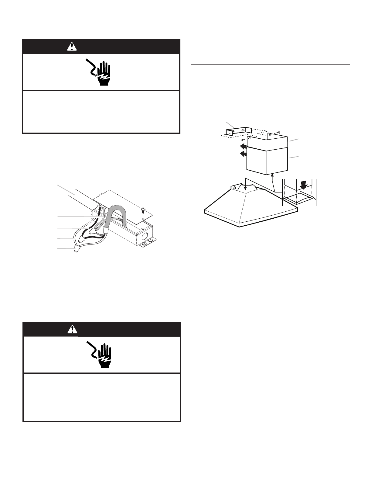
Install Vent Covers
1. When using both upper and lower vent covers, push lower
coverdown onto hood and lift upper cover to ceiling and
installwith (2) 2.9 x 6.5 mm screws.
NOTE: For vented installations, the upper vent cover may be
reversed to hide slots.
Complete Installation
1. For non-vented (recirculating) installations only, install
charcoal lters over the grease lters, using the clips
provided in the kit. See the “Range Hood Care” section.
2. Install metal lters. See the “Range Hood Care” section.
3. Check the operation of the range hood blower and light.
Seethe “Range Hood Use” section.
NOTE: To get the most efcient use from your new range
hood,read the “Range Hood Use” section.
WARNING
Electrical Shock Hazard
Disconnect power before servicing.
Replace all parts and panels before operating.
Failure to do so can result in death or electrical shock.
A
B
C
D
E
A UL listed wire connectors
B. White wires
C. Black wires
D. Green (or bare) wire connected to yellow-green wires
E. Home power supply
WARNING
Electrical Shock Hazard
Electrically ground blower.
Connect ground wire to green and yellow ground wire
in terminal box.
Failure to do so can result in death or electrical shock.
A
B
C
C
D
A. Upper vent cover
B. Lower vent cover
C. 2.9 x 6.5 mm screws
D. Bracket
Loading ...
Loading ...
Loading ...