
Installation & Operation
P300-8P
P300-10
P300-10T
P300-12
P300-12T
P500-12P
POWERED ENCLOSURE
Serial Number:
Date of Purchase:
ROCKFORDFOSGATE.COM
600 South Rockford Drive • Tempe, Arizona 85281
United States
Direct: (480) 967-3565 • Toll Free: (800) 669-9899
Printed In Thailand
102418JF
1230-71030-02
Installation assistance available at:
www.rockfordfosgate.com/rech
2
Dear Customer,
Congratulations on your purchase of the world’s finest brand of car
audio amplifiers. At Rockford Fosgate we are fanatics about musical
reproduction at its best, and we are pleased you chose our product.
Through years of engineering expertise, hand crasmanship
and critical testing procedures, we have created a wide range of
products that reproduce music with all the clarity and richness you
deserve.
For maximum performance we recommend you have your new
Rockford Fosgate product installed by an Authorized Rockford Fosgate
Dealer, as we provide specialized training through Rockford Technical
Training Institute (RTTI). Please read your warranty and retain your
receipt and original carton for possible future use.
Great product and competent installations are only a piece of the
puzzle when it comes to your system. Make sure that your installer is
using 100% authentic installation accessories from Rockford Fosgate in
your installation. Rockford Fosgate has everything from RCA cables and
speaker wire to power wire and battery connectors. Insist on it! Aer all,
your new system deserves nothing but the best.
To add the finishing touch to your new Rockford Fosgate image order
your Rockford accessories, which include everything from T-shirts to
jackets.
Visit our web site for the latest information on all
Rockford products; www.rockfordfosgate.com
or, in the U.S. call 1-800-669-9899 or FAX 1-800-398-3985. For all
other countries, call +001-480-967-3565 or FAX +001-480-966-3983.
Table of Content
If, after reading your manual, you still have questions regarding
this product, we recommend that you see your Rockford
Fosgate dealer. If you need further assistance, you can call us
direct at 1-800-669-9899. Be sure to have your serial number,
model number and date of purchase available when you call.
Safety
This symbol with “WARNING” is intended to alert the
user to the presence of important
instructions. Failure to heed the
instructions will result in severe injury
or death.
This symbol with “CAUTION” is
intended to alert the user to the
presence of important instructions.
Failure to heed the instructions can
result in injury or unit damage.
• To prevent injury and damage to the unit, please read
and follow the instructions in this manual. We want you to
enjoy this system, not get a headache.
• If you feel unsure about installing this system yourself, have
it installed by a qualified Rockford Fosgate technician.
• Before installation, disconnect the battery negative (-)
terminal to prevent damage to the unit, fire and/or possible
injury.
Introduction
©2012 Rockford Corporation. All Rights Reversed. ROCKFORD FOSGATE and associated logos where applicable are registered
trademarks of Rockford Corporation in the United States and/or other
countries. All other trademarks are the property of their respective owners. Specifications subject to change without notice.
PRACTICE SAFE SOUND
Continuous exposure to sound pressure levels over 100dB may cause
permanent hearing loss. High powered auto sound systems may
produce sound pressure levels well over 130dB. Use common sense
and practice safe sound.
PRATIQUEZ UNE ÉCOUTE SANS RISQUES
Une exposition continue à des niveaux de pression acoustique upérieurs à
100 dB peut causer une perte d’acuité auditive permanente. Les systèmes
audio de forte puissance pour auto peuvent produire des niveaux de
pression acoustique bien au-delà de 130 dB. Faites preuve de bon sens et
pratiquez une écoute sans risques
PRACTIQUE EL SONIDO SEGURO
El contacto continuo con niveles de presión de sonido superiores a 100
dB puede causar la pérdida permanente de la audición. Los sistemas de
sonido de alta potencia para automóviles pueden producir niveles de
presión de sonido superiores a los 130 dB. Aplique el sentido común y
practique el sonido seguro.
PRAKTIZIEREN SIE SICHEREN SOUND
Fortgesetzte Geräuschdruckpegel von über 100 dB können beim
Menschen zu permanentem Hörverlust führen. Leistungsstarke
Autosoundsysteme können Geräuschdruckpegel erzeugen, die weit über
130 dB liegen. Bitte wenden Sie gesunden Menschenverstand an und
praktizieren Sie sicheren Sound.
OSSERVATE LE REGOLE DEL SUONO SENZA PERICOLI
La costante esposizione a livelli di pressione acustica al di sopra dei
100dB possono causare la perdita permanente dell’udito. I sistemi
audio ad alta potenza possono produrre livelli di pressione acustica ben
superiori ai 130dB. Si consiglia il buon senso e l’osservanza delle regole
del suono senza pericoli
2 Introduction
3-5 Specifications
6 Design Features
7-8 Installation
Installation Considerations
Battery and Charging
Wiring the System
9 Operation
Adjusting Gain / Crossover
Phase Switch
Input Level
Auto Turn-on
Punch Bass / Remote Punch Level
10-21 Additional Languages
French
Spanish
German
Italian
22 Limited Warranty Information

3
Specifications
Model P300-10 P300-12 P300-8P
Description 10” Powered Subwoofer 12” Powered Subwoofer 8” Powered Subwoofer
Power Rating
(RMS/Peak)
300W / 600W 300W / 600W 300W / 600W
Crossover Slope 12dB/Oct 12dB/Oct 12dB/Oct
Crossover
Frequency
Variable 50Hz-200Hz Variable 50Hz-200Hz Variable 50Hz-200Hz
Punch Bass Variable 0 - +12dB @ 45Hz Variable 0 - +12dB @ 45Hz Variable 0 - +12dB @ 45Hz
Frequency
Response
35Hz - 200Hz 35Hz - 200Hz 35Hz - 200Hz
Input Sensitivity 100mV - 3V 100mV - 3V 100mV - 3V
Fuse Rating 20A (2 X 10A) 20A (2 X 10A) 20A (2 X 10A)
Overall
Dimensions
(HxWxD)
13.3” x 18.0” x 8.9”/5.9”
(33.7cm x 45.7cm x
22.6/15cm)
15.0” x 19.8” x 11.0”/7.0”
(38.1cm x 50.3cm x
28/17.8cm)
11.38” x 17.6” x 4.84”/3.69”
(28.9cm x 44.8cm x
14.1/9.36cm)
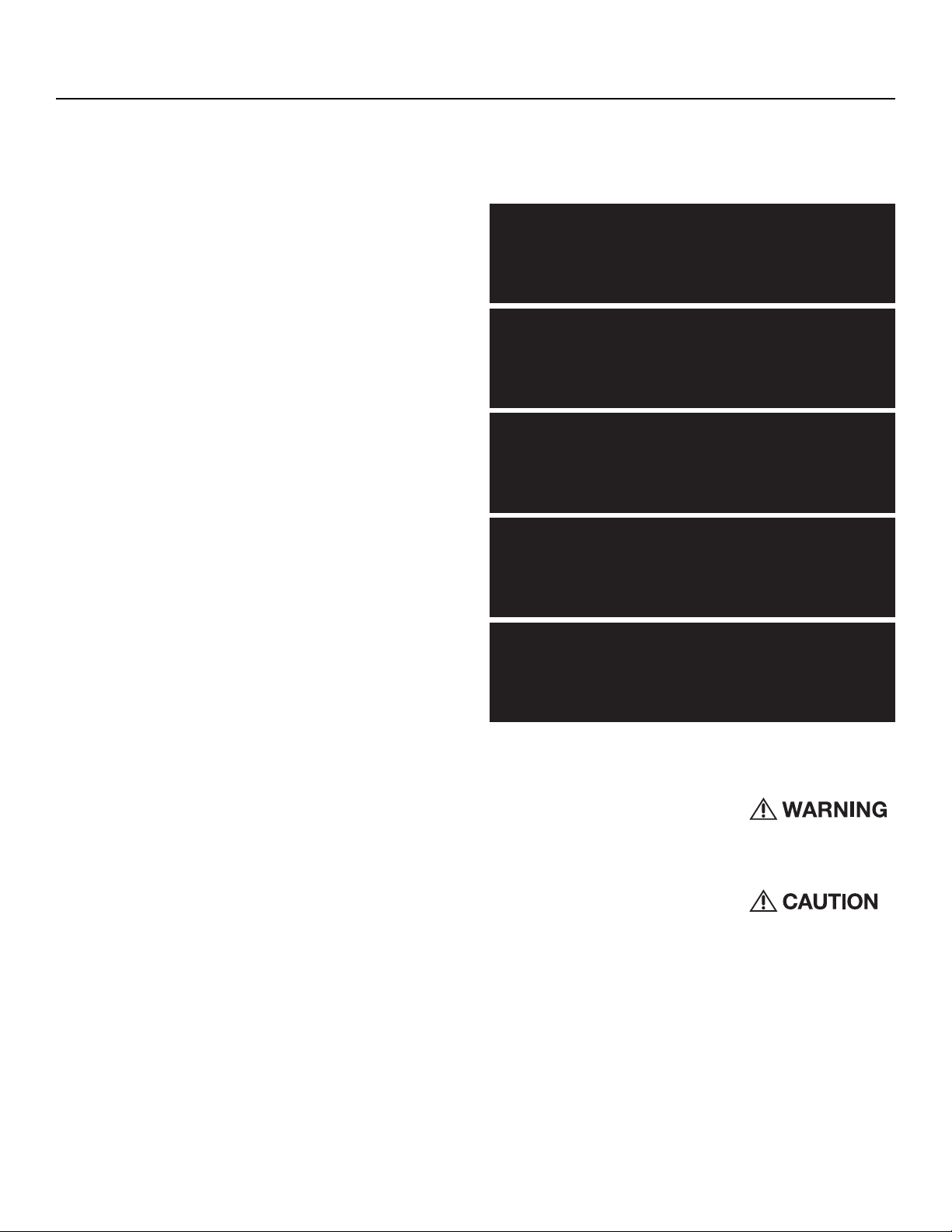
See illus.-1.1 for additional dimensions
CEA 2006
Power ratings on Rockford Fosgate amplifiers conform
to CEA-2006 industry standards. These guidelines
mean your amplifier’s output power ratings are REAL
POWER numbers, not inflated marketing ratings.
CEA 2031
Power handling on Rockford Fosgate speakers
conform to CEA-2031 industry standards. This means
your speaker has the capacity to handle power under
continuous demand, not instantaneous power handling,
that over time can damage voice coils.
Model P300-10T P300-12T P500-12P
Description 10” Powered Subwoofer 12” Powered Subwoofer 12” Powered Subwoofer
Power Rating
(RMS/Peak)
300W / 600W 300W / 600W 500W / 1000W
Crossover Slope 12dB/Oct 12dB/Oct 12dB/Oct
Crossover Frequency Variable 50Hz-200Hz Variable 50Hz-200Hz Variable 50Hz-200Hz
Punch Bass Variable 0 - +12dB @ 45Hz Variable 0 - +12dB @ 45Hz Variable 0 - +12dB @ 45Hz
Frequency Response 35Hz - 200Hz 35Hz - 200Hz 20Hz - 200Hz
Input Sensitivity 100mV - 3V 100mV - 3V 130mV - 5V
Fuse Rating 20A (2 X 10A) 20A (2 X 10A) 30A (2 X 15A)
Overall Dimensions
(HxWxD)
13.31” x 21.73” x
11.0”/7.0”
(33.8cm x 55.2cm x
20.1/12.2cm)
14.96” x 25.83.” x
8.46”/4.8”
(38cm x 65.6cm x
21.5/12.2cm)
12.88” x 24.76.” x
”10.91/7.71”
(32.7cm x 62.9cm x
27.7/189.2cm)
See illus.-1.1 for additional dimensions
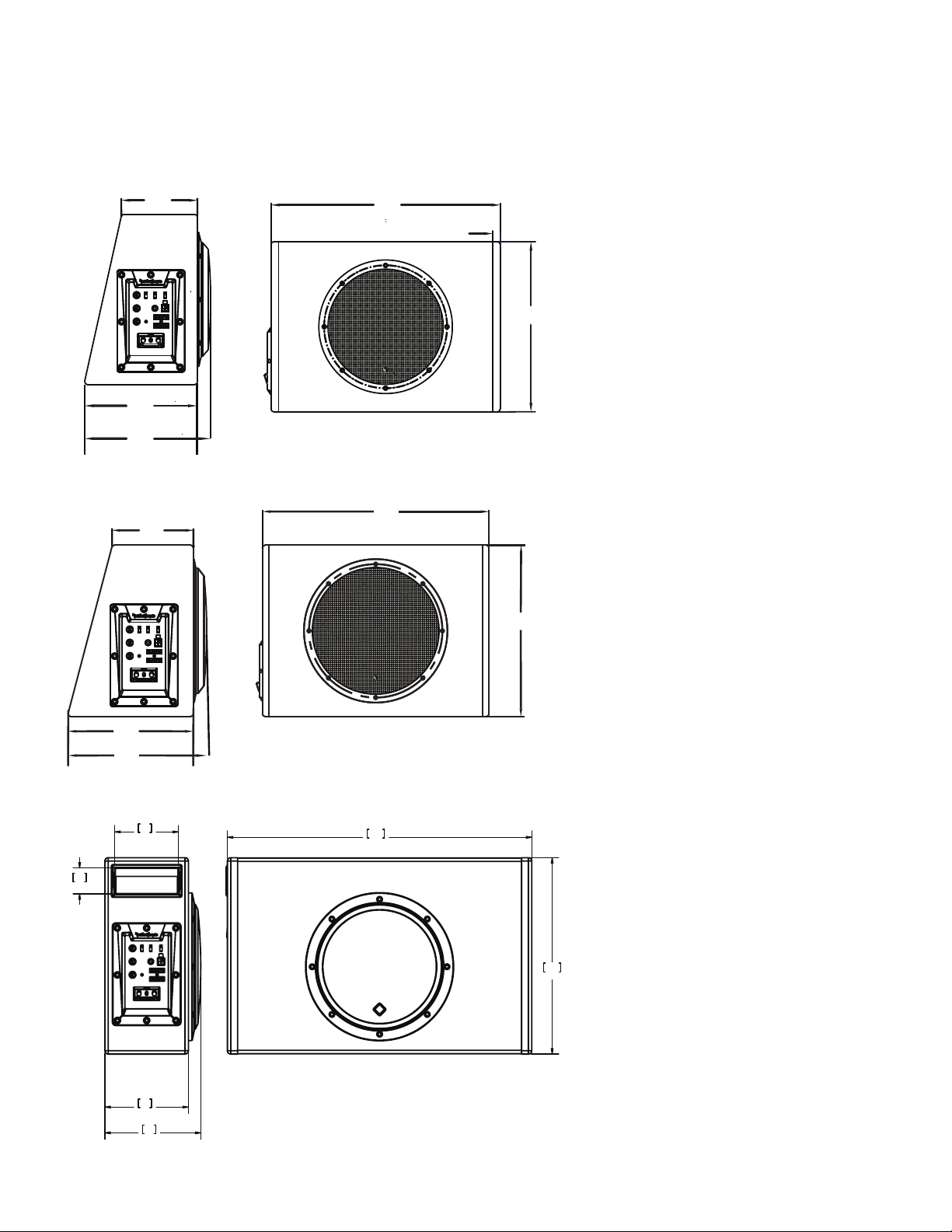
Specifications
illus.-1.1
4
[13.31]
338
[0.59]
15
[17.91]
455
[5.98]
152.0
[8.82]
224.0
P300-10
17.6
448
11.4
289
1.5
38
3.7
94
5.6
141
4.8
123
P300-8P
[14.96]
380
[19.80]
[7.08]
180
[10.94]
278
P300-12
[12.1]
307
[9.85]
250
5
Specifications
25.8
656
15.0
380
4.8
122
8.5
215
P300-12T
7.5
190
7.9
201
4.8
122
21.7
552
13.3
338
P300-10T
P500-12P
6
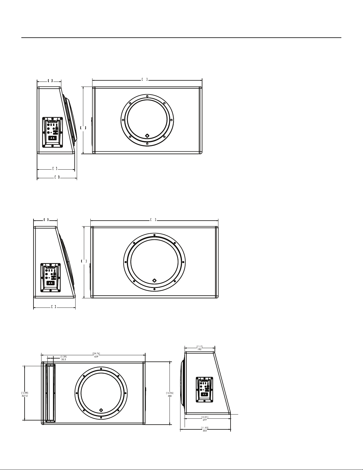
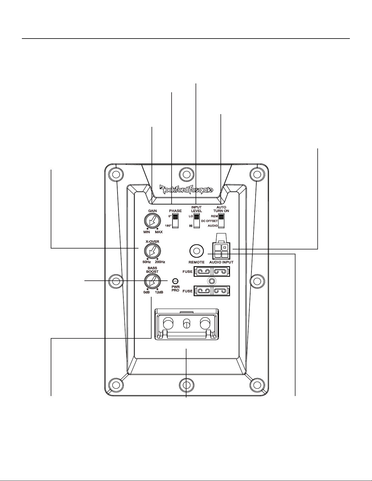
Design Features
illus.-2.1
Power Connector
The power connector allows for quick
connection and disconnection of the
amplifier’s Remote, power and ground
source. The power and ground are
set-screw wire connectors and will
accommodate 4 AWG. The remote is
a set-screw wire connector and will
accommodate 8 AWG.
Phase Switch
Allows you to select the output
phase of the amplifier between 0°
and 180°.
Input Level
Set the Input Level switch to match the outputs of your
source unit.(LO - RCA or HI - Speaker Level)
Auto Turn On
Three different automatic turn-on modes can be
selected; REM(+12V), DC Offset, and Audio.
Variable Crossover
Is a built-in 12dB/octave Butterworth
filter with a crossover point variable from
50Hz to 200Hz.
Punch Bass
This is an adjustable Bass control
adjustment variable from 0dB to +12dB
@ 45Hz.
Power/Protect LED
Power LED illuminates
blue when the unit
is turned on. Protect
LED illuminates red
if a short circuit or to
low of an impedance
is detected at the
speaker connections.
The amplifier will
automatically shut
down if this occurs.
Remote Punch Level
When connected, the “Gain Control”
is linked and allows you to remotely
control the output level of the amplifier
from the dash or center console.
Audio Input
The RCA/Speaker Harness utilizes either
speaker level (high-level) or RCA (low-
level) inputs.
Gain Control
The input gain control is preset to
match the output of most source
units.
7
Installation
Contents
• Punch Powered Loaded Enclosure
• RCA/Speaker Harness
• Power Connector
• Remote Punch Level Control
• Installation & Operation Manual
• 2X 10A Fuses Spare/2X 15A Fuses Spare (P500-12P only)
Installation Considerations
The following is a list of tools needed for installation:
This section focuses on some of the vehicle considerations
for installing your new powered loaded enclsoure. Pre-
planning your system layout and best wiring routes will
save installation time. When deciding on the layout of your
new system, be sure that each component will be easily
accessible for making adjustments.
If you feel unsure about installing this system yourself, have
it installed by a qualified technician.
Before installation, disconnect the
battery negative (-) terminal to prevent
damage to the unit, fire and/or possible
injury.
Before beginning any installation,
follow these simple rules:
1. Be sure to carefully read and understand the instructions
before attempting to install the unit.
2. For safety, disconnect the negative lead from the battery
prior to beginning the installation.
3. For easier assembly, we suggest you run all wires prior to
mounting your unit in place.
4. Route all of the RCA cables close together and away from
any high current wires.
5. Use high quality connectors for a reliable installation and to
minimize signal or power loss.
6. Think before you drill! Be careful not to cut or drill into gas
tanks, fuel lines, brake or hydraulic lines, vacuum lines or
electrical wiring when working on any vehicle.
7. Never run wires underneath the vehicle. Running the wires
inside the vehicle provides the best protection.
• Fuse-holder and fuse. (See
specifications for fuse
rating)
• Volt/Ohm Meter
• Wire strippers
• Wire crimpers
• Wire cutters
• #2 Phillips screwdriver
• Battery post wrench
• Hand held drill w/assorted
bits
• Assorted connectors
• Adequate Length—Red
Power Wire
• Adequate Length—Remote
Turn-on Wire
• Adequate Length—Black
Grounding Wire
8. Avoid running wires over or through sharp edges. Use
rubber or plastic grommets to protect any wires routed
through metal, especially the firewall.
9. ALWAYS protect the battery and electrical system from
damage with proper fusing. Install the appropriate fuse
holder and fuse on the +12V power wire within 18” (45.7
cm) of the battery terminal.
10. When grounding to the chassis of the vehicle, scrape
all paint from the metal to ensure a good, clean ground
connection. Grounding connections should be as short as
possible and always be connected to metal that is welded
to the main body, or chassis, of the vehicle. Seatbelt bolts
should never be used for connecting to ground.
Mounting Locations
Trunk or Passenger Compartment Mounting
Choose a structurally sound location to mount your powered
loaded enclosure. Mount the enclosure in such a manner
that the amplifier has a minimum of 1” (2.54cm) of air gap
around the amplifier’s heatsink to provide proper cooling
to ensure optimum performance of the amplifier is strongly
recommended.
Battery and Charging
Amplifiers will put an increased load on the vehicle’s battery
and charging system. We recommend checking your
alternator and battery condition to ensure that the electrical
system has enough capacity to handle the increased load
of your stereo system. Stock electrical systems which are in
good condition should be able to handle the extra load of any
Prime Series amplifier without problems, although battery
and alternator life can be reduced slightly. To maximize the
performance of your amplifier, we suggest the use of a heavy
duty battery and an energy storage capacitor.
Wiring the System
If you do not feel comfortable with
wiring your new unit, please see your
local Authorized Rockford Fosgate
Dealer for installation.
Before installation, disconnect the
battery negative (-) terminal to prevent
damage to the unit, fire and/or possible
injury.
Avoid running power wires near
the low level input cables, antenna,
power leads, sensitive equipment
or harnesses. The power wires carry
substantial current and could induce
noise into the audio system.
1. Plan the wire routing. Keep RCA cables close together but
isolated from the amplifier’s power cables and any high
power auto accessories, especially electric motors. This is
done to prevent coupling the noise from radiated electrical
fields into the audio signal. When feeding the wires through
the firewall or any metal barrier, protect them with plastic or
rubber grommets to prevent short circuits. Leave the wires
long at this point to adjust for a precise fit at a later time.
8
Installation
2. Prepare the RED wire (power cable) for attachment to the
amplifier by stripping 1/2” of insulation from the end of the
wire. Insert the bared wire into the B+ terminal of the power
connector and tighten the set screw to secure the cable in
place.
NOTE: The B+ cable MUST be fused 18” or less from the
vehicle’s battery. Install the fuseholder under the hood and
ensure connections are water tight.
3. Trim the RED wire (power cable) within 18” of the battery
and splice in a inline fuse holder (not supplied). See
Specifications for the rating of the fuse to be used. DO NOT
install the fuse at this time.
4. Strip 1/2” from the battery end of the power cable and crimp
an appropriate size ring terminal to the cable. Use the ring
terminal to connect to the battery positive terminal.
5. Prepare the BLACK wire (Ground cable) for attachment to
the amplifier by stripping 1/2” of insulation from the end of
the wire. Insert the bare wire into the GROUND terminal of
the power connector and tighten the set screw to secure
the cable in place. Prepare the chassis ground by scraping
any paint from the metal surface and thoroughly clean the
area of all dirt and grease. Strip the other end of the wire
and attach a ring connector. Fasten the cable to the chassis
using a non-anodized screw and a star washer.
NOTE: Keep the length of the BLACK wire (Ground) as short
as possible. Always less than 30”.
6. Prepare the Remote turn-on wire for attachment to the
amplifier by stripping 1/2” of insulation from the end of the
wire. Insert the bared wire into the REMOTE terminal of the
power connector and tighten the set screw to secure the
wire in place. Connect the other end of the Remote wire to
a switched 12 volt positive source. The switched voltage is
usually taken from the source unit’s remote amp on lead.
If the source unit does not have this output available, the
recommended solution is to wire a mechanical switch in line
with a 12 volt source to activate the amplifier.
NOTE: In the event that a switched +12V is not available,
either DC offset or Audio sense can be selected for amplifier
turn-on.
7. Connect the power connector to the mating connector at
the amplifier.
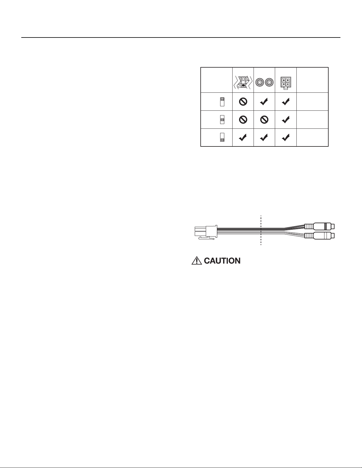
8. Connect from source signal by plugging the RCA cables
into the RCA/Speaker Harness input jacks, then insert the
four pin Molex connector into the mating four pin INPUT
connector at the amplifier.
NOTE: When the installation requires a High Level(Speaker)
input, the RCA/Speaker Harness will need to be cut on the
speaker wire side of the y-splitter.Then connect the white to
the left(+), white/black to the left(-), grey to the right(+), and
grey/black to the right(-) corresponding vehicle wires.
Always ensure power is off or disconnected at the amplifier
before connecting RCA cables. Failure to do so may cause
damage to the amplifier and/or connected components.
9. Perform a final check of the
completed system wiring to ensure that
all connections are accurate. Check
all power and ground connections for
frayed wires and loose connections
which could cause problems. Install
inline fuse near battery connection.
illus.-3.1
Cut
illus.-4.1
LOW INPUT
HI-LEVEL
INPUT
AUTO TURN ON NOTES
Requires 4mV signal
Needs 6V DC on
factory speaker wires
Use hi-level or low-
level input
AUDIO
DC OFFSET
REM
AUDIO
DC OFFSET
REM
AUDIO
DC OFFSET
REM
REM

9
Operation/Troubleshooting
Troubleshooting
NOTE: If you are having problems after installation follow the
Troubleshooting procedures below.
Step 1. Check Amplifier for proper connections. Verify that
POWER light is on. If POWER light is on skip to Step 3, if
not continue.
1. Check in-line fuse on battery positive cable. Replace if necessary.
2. Check fuse(s) on amplifier. Replace if necessary. Do not exceed
10A.
3. Verify that Ground connection is connected to clean metal on the
vehicle’s chassis. Repair/replace if necessary.
4. Verify there is 9 to 14.4 Volts present at the positive battery and
remote turn-on cable. Verify quality connections for both cables
at amplifier, stereo, and battery/fuseholder. Repair/replace if
necessary.
Step 2. Protect light is on.
1. If the Protect light is on, this is a sign of a possible short in the
speaker connections. Check for proper speaker connections
and use a volt/ohm meter to check for possible shorts in the
speaker wiring. Too low of a speaker impedance may also cause
Protect to light.
Step 3. Check Amplifier for audio output.
1. Verify good RCA input connections at stereo and amplifier.
Check entire length of cables for kinks, splices, etc. Test RCA
inputs for AC volts with stereo on. Repair/replace if necessary.
2. Disconnect RCA input from amplifier. Connect RCA input from
test stereo directly to amplifier input.
Step 4. Check Amplifier if you experience Turn-on Pop.
1. Disconnect input signal to amplifier and turn amplifier on and off.
2. If the noise is eliminated, connect the REMOTE lead of amplifier
to source unit with a delay turn-on module.
OR
1. Use a different 12 Volt source for REMOTE lead of amplifier.
Step 5. Check Amplifier if you experience excess Engine Noise.
1. Route all signal carrying wires (RCA, Speaker cables) away from
power and ground wires.
OR
1. Bypass any and all electrical components between the stereo
and the amplifier(s). Connect stereo directly to input of amplifier.
If noise goes away the unit being bypassed is the cause of the
noise.
OR
1. Remove existing ground wires for all electrical components.
Reground wires to different locations. Verify that grounding
location is clean, shiny metal free of paint, rust etc.
OR
1. Add secondary ground cable from negative battery terminal to
the chassis metal or engine block of vehicle.
OR
1. Have alternator and battery load tested by your mechanic.
Verify good working order of vehicle electrical system including
distributor, spark plugs, spark plug wires, voltage regulator etc.
Adjusting Gain
1. Turn amplifier gain to minimum (counter-clockwise).
2. Turn the source unit volume up to 7/8 maximum (or when
distortion is just inaudible).
3. Slowly increase amplifier gain control until adequate volume
is achieved.
NOTE: Best signal to noise and dynamic range are realized
with gain set to minimum. For a more in depth setting
procedure, contact Rockford Technical Support.
Avoid setting amplifier gain high
as noise and distortion will greatly
increase.
Adjusting Crossover Frequency
The crossover frequency can be adjusted between 50-
200Hz.The crossover is set to LP (Low Pass) only. Turn the
crossover adjustment knob all the way down. With the system
playing, turn the crossover adjustment knob up slowly until
the desired crossover point is achieved.
Phase Switch
Allows you to conveniently switch the output phase of the
amplifier between 0° and 180°. This has the same effect as
physically reversing the Positive (+) and Negative (-) speaker
wires
Input Level
Set the Input Level switch to match the outputs of your source
unit.(LO - RCA or HI - Speaker Level)
Auto Turn On(illus.-3.1)
Three different automatic turn-on modes can be selected;
REM(+12V), DC Offset, and Audio.
Remote: Set the switch to REM to use the remote turn-on
lead from your source unit.
DC Offset: Set the switch to DC Offset to detect a DC offset
from the HI-Level speaker outputs when the source unit has
been turned on.
Audio: Set the switch to Audio to detect the incoming audio
signal from your source unit and automatically turn on your
powered loaded enclosure.
NOTE: Using either the DC Offset or Audio mode causes the
REM on the power connector to have +12V out for turning on
additional amplifiers.
Punch Bass
This works along with the crossover switch on the amplifier.
When set to Low-Pass (LP) operation, this is a variable Bass
Boost. Set this to your personal preference while listening to
the system.
Over excursion and subsequent
damage may occur at high levels of
boost.
Remote Punch Level Control
When connected, the “Gain Control” is linked and allows you
to remotely control the output level of the amplifier from the
dash or center console..

10
Français
Particularités Techniques (illus.-2.1)
DEL d’alimentation / DEL de protection
Cette DEL vert s’illumine lorsque l’appareil est allumé. Cette DEL rouge
s’illumine si un court-circuit ou une impédance trop basse est détecté au
niveau des connexions de haut-parleur. L’ampli s’éteint automatiquement si
cela se produit.
Prises d’entrée RCA
Les prises RCA de norme industrielle permettent une connexion facile
pour les entrées de signaux. Ils sont plaqués de nickelés pour résister à la
détérioration de signal due à l’effet de la corrosion.
Commande de gain
La commande de gain d’entrée est préréglée de manière à correspondre à la
sortie de la plupart des unités source. Elle peut être réglée en fonction d’une
variété d’unités source.
Filtre phase
Permet de sélectionner la phase de sortie de l’amplificateur entre 0° et 180°.
Filtre variable
Les amplificateurs sont dotés d’un filtre de Butterworth intégré de 12dB/
octave dont le point de fréquence varie entre 50 Hz et 200 Hz.
Punch Bass
Il s’agit d’un niveau réglable Bass contrôle centré à 45 Hz @ 12dB/octave.
à distance Niveau Punch
Lorsqu’il est connecté, le “gain” est liée et vous permet de contrôler à
distance le niveau de
sortie de l’amplificateur du tableau de bord ou la console centrale.
Entrée sonore
Le harnais de RCA/Speaker utilise le haut-parleur de niveau (à niveau élevé)
ou les entrées (inférieures) de RCA.
Niveau saisie
Placez le commutateur de niveau saisie pour apparier les sorties de votre
unité de source. (LO - RCA ou HI - haut-parleur de niveau)
Automatique allumez-vous
Trois modes d’ouverture automatiques différents peuvent être choisis ; Rem
(12V), décalage du courant d’obscurité, et acoustique.
Prise d’alimentation
La prise d’alimentation tient compte de la connexion et du débranchage
rapides du distant de l’amplificateur, de la puissance et de la source de la
terre. La puissance et la terre sont des connecteurs de fil de vis de réglage
et faciliteront 4 AWG. Le distant est un connecteur de fil de vis de réglage et
facilitera 8 AWG.
Considérations Concernant L’installation
Voici la liste d’outils requis pour l’installation :
REMARQUE: Nous recommandons l’utilisation d’un fil de 4 AWG pour les
prises d’alimentation (B+) et de masse (GND).
Cette section traite de points concernant le véhicule dont il faut tenir
compte pour l’installation de votre nouvel ampli.Vous sauverez du temps en
planifiant à l’avance la disposition du système et du câblage.Assurez-vous,
entre autres, que chaque composant du système est facilement accessible
pour les réglages.
MISE EN GARDE : si vous vous sentez incapable d’installer l’appareil vous-
même, confiez la tâche à un technicien qualifié.
MISE EN GARDE : avant d’entamer l’installation, déconnectez la broche
négative (-) de la batterie pour éviter tout risque de blessures, d’incendie
ou de dommages à l’appareil.
Avant de commencer l’installation, suivez ces règles toutes simples :
1. Prenez soin de bien lire et comprendre les instructions avant d’installer
l’appareil.
2. Par mesure de sécurité, veuillez débrancher le fil négatif de la batterie
avant de commencer l’installation.
3. Pour faciliter le montage, nous vous suggérons de dérouler tous les fils
avant d’installer l’appareil.
4. Acheminez tous les câbles RCA de façon groupée, à l’écart des fils à
courant élevé.
5. Utilisez des connecteurs de haute qualité pour assurer une installation
fiable et minimiser la perte de signal ou de puissance.
6. Réfléchissez avant de percer quoique ce soit! Faites attention de ne pas
couper ou percer le réservoir d’essence, les conduites de carburant, de
frein, hydrauliques ou de dépression, ou le câblage électrique lorsque
vous travaillez sur un véhicule.
7. Ne faites jamais passer les fils sous le véhicule. Il vaut mieux les installer
à l’intérieur du véhicule pour assurer une meilleure protection.
8. Évitez de faire passer les fils par dessus ou à travers des bords
tranchants.Tout fil acheminé à travers du métal, un pare-feu en particulier,
doit être protégé avec des bagues en caoutchouc ou plastique.
9. Protégez TOUJOURS la batterie et le circuit électrique des dommages
potentiels à l’aide de fusibles. Installez un porte-fusible et un fusible
appropriés sur le câble d’alimentation de +12 V à moins de 45,7 cm de
la borne de batterie.
10. Préparez la masse du châssis en grattant toute trace de peinture de
la surface métallique afin d’assurer une bonne mise à la masse. Les
connexions de masse doivent être aussi courtes que possible et
toujours connectées à du métal soudé à la carrosserie ou au châssis
du véhicule.
Emplacements De Montage
Montage dans le coffre ou l’habitacle
Choisissez un emplacement structurellement sain pour monter votre rubrique
de description chargée actionnée. Montez la rubrique de description de
façon que l’amplificateur ait un minimum de 2,54cm de l’entrefer autour du
radiateur de l’amplificateur pour fournir le refroidissement approprié pour
assurer la représentation optima de l’amplificateur est vivement recommandé.
Batterie Et Charge
Les amplificateurs exercent une charge accrue sur la batterie et le
système de charge du véhicule.Nous vous conseillons de vérifier l’état de
l’alternateur et de la batterie pour vous assurer que le système électrique
puisse supporter la charge accrue de votre système stéréo. Les systèmes
électriques ordinaires en bon état sont normalement capables de fournir
sans problème la charge supplémentaire requise par les amplis Power.
Toutefois, la durée de vie de la batterie et de l’alternateur peut s’en trouver
affectée légèrement. Pour maximiser la performance de votre ampli, nous
vous suggérons d’utiliser une batterie à usage intensif et un condensateur
de stockage d’énergie.
CÂBLAGE DU SYSTÈME (illus.-3.1 & 4.1)
MISE EN GARDE: si vous ne vous sentez pas à l’aise pour effectuer vous-
même le câblage de votre nouvel appareil, veuillez confier l’installation à
votre distributeur agréé Rockford Fosgate.
MISE EN GARDE: avant d’entamer l’installation, déconnectez la broche
négative (-) de la batterie pour éviter tout risque de blessures, d’incendie ou
• Porte-fusible et fusible. (Voir les
spécifications concernant la
capacité des fusibles)
• Voltmètre-ohmmètre
• Pince à dénuder
• Pince à sertir
• Coupe-fils
• Tournevis à embout cruciforme
no 2
• Clé de borne de batterie
• Perceuse à main avec mèches
assorties
• Tube thermorétrécissable de
1/8 po de diamètre
• Connecteurs assortis
• Longueur adéquate — Fil
d’alimentation rouge
• Longueur adéquate — Fil
d’allumage à distance
• Longueur adéquate — Fil de
masse noir

11
Françias
de dommages à l’appareil.
MISE EN GARDE: évitez de faire passer les fils d’alimentation près des
câbles d’entrée de signaux faibles, de l’antenne, des câbles d’alimentation,
des équipements ou faisceaux sensibles. Les fils d’alimentation transportent
un courant élevé et peuvent produire du bruit dans le système audio.
1. Planifiez l’acheminement des fils.Gardez les câbles RCA ensemble
mais en les isolant des câbles d’alimentation de l’ampli et des autres
accessoires automobiles de forte puissance, particulièrement les moteurs
électriques, pour éviter que le signal audio ne subisse d’interférence de
bruit provenant de champs de rayonnement électriques. Si vous faites
passer les fils par un pare-feu ou autre barrière métallique, protégez-
les à l’aide de bagues en caoutchouc ou en plastique pour éviter les
courts-circuits. Conservez toute la longueur des fils pour l’instant.Vous
l’ajusterez plus tard.
REMARQUE: Nous recommandons l’utilisation d’un fil de 4AWG pour les
prises d’alimentation (B+) et de masse (GND).
2. Préparez le fil d’alimentation ROUGE à connecter à l’amplificateur en
dénudant son extrémité sur 13 mm. Insérez la partie dénudée dans la
borne B+ de la prise d’alimentation, puis fixez le fil en vissant la vis
sans tête.
REMARQUE: Le câble B+ DOIT comporter un fusible à 45,7 cm ou moins
de la batterie du véhicule. Installez le porte-fusible sous le capot et assurez-
vous que les connexions sont étanches.
3. Coupez le fil ROUGE (câble d’alimentation) à moins de 45,7 cm de la
batterie et épissez un porte-fusible en ligne.Voir les Spécifications en
ce qui concerne la capacité du fusible à utiliser.N’INSTALLEZ PAS le
fusible pour l’instant.
4. Dénudez l’autre extrémité du fil d’alimentation sur 13 mm environ,
sertissez-la dans un connecteur en anneau de taille adéquate, puis
fixez celui-ci à la borne positive de la batterie.
5. Préparez le fil de masse NOIR à connecter à l’amplificateur en dénudant
son extrémité sur 13 mm. Insérez la partie dénudée dans la borne GND
de la prise d’alimentation, puis fixez le fil en vissant la vis sans tête.
Préparez la masse du châssis en grattant toute trace de peinture de
la surface métallique et en nettoyant soigneusement pour éliminer tout
dépôt de saleté et de graisse.Dénudez l’autre extrémité du fil et fixez un
connecteur en anneau. Fixez le câble au châssis à l’aide d’une vis non
anodisée et une rondelle en étoile.
REMARQUE: Gardez le fil NOIR (masse) aussi court que possible.Toujours
inférieur à 76,2 cm.
6. Préparez le fil de télécommande (REM) à connecter à l’amplificateur en
dénudant son extrémité sur 13 mm. Insérez la partie dénudée dans la
borne REM de la prise d’alimentation, puis fixez le fil en vissant la vis
sans tête.Connectez l’autre extrémité du fil REM à une source positive
commutée de 12 volts. La tension commutée provient généralement
du câble d’allumage d’ampli de la source audio. Si la source audio
ne comporte pas une telle sortie, nous recommandons de raccorder
un interrupteur mécanique en ligne avec une source de 12 volts pour
activer l’ampli.
REMARQUE: Au cas où un 12V commuté ne serait pas disponible, le
décalage du courant d’obscurité ou le sens sonore peut être choisi pour la
mise en fonction d’amplificateur.
7. Branchez la prise d’alimentation au connecteur de accouplement à
l’amplificateur.
8. Connecter du signal source en branchant les câbles RCA dans les
prises d’entrée de faisceau RCA/Enceintes, puis insérer le connecteur
Molex à quatre broches dans le connecteur ENTRÉE correspondant à
quatre broches au niveau de l’amplificateur.
REMARQUE : Lorsquel’installationrequiertuneentréedeNiveaufort(Enceinte
),lefaisceau RCA/Enceintes devra être coupé sur le côté fil d’enceinte du
répartiteur en Y. Connecter ensuite le fil blanc sur la gauche (+), le fil blanc/
noir sur la gauche (-), le fil gris sur la droite (+) et le fil gris/noir sur la droite
(-) correspondants aux fils de véhicules.
MISE EN GARDE : Assurez-vous toujours que l’alimentation est éteinte ou
débranchée
au niveau de l’amplificateur avant de connecter les câbles RCA. Le non-
respect de cette consigne peut entraîner des dommages pour l’amplificateur
ou les éléments raccordés à celui-ci.
9. Effectuez une vérification finale du câblage pour vous assurer que
toutes les connexions sont bien mises.Vérifiez toutes les connexions
d’alimentation et de mise à la masse en vue de fils effilochés et de
connexions desserrées pouvant causer des problèmes. Installez le
fusible en ligne près de la connexion de la batterie.
Réglage Du Gain
Procédez de la manière suivante pour chaque voie séparément.
Pour régler le gain, tournez le bouton de gain de l’ampli vers son niveau le
plus bas (sens anti-horaire). Augmentez le volume de la source audio jusqu’à
produire une distorsion audible, puis baissez-le jusqu’à ce que la distorsion
devienne inaudible.Cela correspondant généralement au maximum du
volume sur la plupart des unités source.Augmentez ensuite le gain de l’ampli
jusqu’à ce que le volume soit adéquat.
REMARQUE: Mettez le gain au minimum pour assurer le meilleur rapport
signal/bruit et la meilleure gamme dynamique. Pour la plupart des utilisateurs,
un réglage au milieu assure un niveau de gain et de volume adéquat.
MISE EN GARDE: Évitez de régler le gain de l’ampli trop haut car cela
entraîne une augmentation significative du bruit et des distorsions.
REMARQUE: pour un réglage plus approfondi,communiquez avec le support
technique de Rockford.
Réglage De La Fréquence Du Filtre Passif
La fréquence de coupure est réglable entre 50 Hz et 200 Hz. Le filtre
fonctionne en mode passe-bas seulement. Tournez le bouton de réglage du
filtre à fond vers la gauche.Avec le système en marche, tournez lentement le
bouton de réglage vers la droite jusqu’à la fréquence de coupure souhaitée.
Une fréquence d’environ 80 Hz constitue un bon point de départ.
Filtre Phase
Permet de sélectionner la phase de sortie de l’amplificateur entre 0° et 180°.
Niveau Saisie
Placez le commutateur de niveau saisie pour apparier les sorties de votre
unité de source. (LO - RCA ou HI - haut-parleur de niveau)
Automatique Allumez-vous (illus.-3.1)
Trois modes d’ouverture automatiques différents peuvent être choisis ; Rem
(12V), décalage du courant d’obscurité, et acoustique.
Distant: Placez le commutateur à REM pour utiliser le fil de sortie d’ouverture
à distance à partir de votre unité de source.
Décalage du courant d’obscurité: Placez le commutateur au décalage du
courant d’obscurité pour détecter un décalage du courant d’obscurité des
sorties de haut-parleur de Salut-Level quand l’unité de source a été allumée.
Acoustique: Placez le commutateur à l’audio pour détecter le signal sonore
entrant à partir de votre unité de source et pour allumer automatiquement
votre rubrique de description chargée actionnée.
REMARQUE: Utilisant le décalage du courant d’obscurité ou le mode sonore
fait avoir le rem sur la prise d’alimentation 12V dehors pour mettre en marche
les amplificateurs supplémentaires.
Punch Bass
Esto funciona junto con el interruptor de cruce en el amplificador. Cuando
está ajustado para la operación en Pasa Bajos (Low Pass, LP) esto es un
Refuerzo de Bajos variable. Réglez-le selon votre goût tout en écoutant le
système.
MISE EN GARDE: Évitez de régler le gain de l’ampli trop haut car cela
entraîne une augmentation significative du bruit et des distorsions.
Télécommande De Niveau Punch
Lorsqu’il est connecté, le “gain” est liée et vous permet de contrôler à

distance le niveau de sortie de l’amplificateur du tableau de bord ou la
console centrale.
Dépannage
REMARQUE: si vous éprouvez des difficultés après l’installation,appliquez
les procédures de dépannage ci-dessous.
Step 1. Vérifiez que les connexions de l’ampli sont bienmises. Vérifiez que
le voyant POWER est allumé.Si c’est le cas,passez à l’étape 3,sinon
poursuivez.
1. Vérifiez le fusible en ligne du câble positif de batterie.Effectuez un
remplacement au besoin.
2. Vérifiez les fusibles de l’ampli.Effectuez un remplacement au besoin.
3. Vérifiez que la connexion demise à lamasse est branchée à une
surfacemétallique propre du châssis du véhicule.Procédez à une
réparation ou un remplacement si nécessaire.
4. Vérifiez la présence d’un courant de 9 à 16 volts au niveau de la borne
positive de la batterie et du câble d’allumage à distance. Vérifiez la
qualité des connexions des deux câbles au niveau de l’ampli,de la
stéréo,de la batterie et du porte-fusible.Procédez à une réparation ou
un remplacement si nécessaire.
Step 2. Le voyant de protection ou thermique est allumé.
1. Si le voyant de protection est activé,cela indique la présence possible
d’un court-circuit dans les connexions de hautparleur. Vérifiez le
branchement des enceintes et utilisez unmultimètre pour confirmer
l’absence de courts-circuits dans leur câblage. Le voyant de protection
peut s’allumer si l’impédance de haut-parleur est trop basse.
2. Si la luz de temperatura (Thermal) está encendida,compruebe si la
impedancia del altavoz es correcta,vuelva a cablear si es necesario.
Esto también puede ser una indicación de que se usa el amplificador
a niveles de potenciamuy altos sin tener el flujo de aire adecuado
alrededor del amplificador.Apague el sistema y permita que se enfríe
el amplificador. Compruebe que el sistema de carga del vehículo
estémanteniendo el voltaje adecuado.Si el elemento anterior no resuelve
el problema,es posible que haya una falla en el amplificador,llame a
servicio al cliente para conseguir ayuda.
Step 3. Vérifiez la sortie audio de l’ampli.
1. Vérifiez que les connexions d’entrée RCA sont bonnes au niveau de
la stéréo et de l’ampli.Vérifiez s’il y a des problèmes de torsion ou
d’épissure tout le long des câbles,etc.Testez la présence de courant
c.a.au niveau des entrées RCA lorsque la stéréo est allumée.Procédez
à une réparation ou un remplacement si nécessaire.
2. Débranchez l’entrée RCA de l’ampli.Branchez l’entrée RCA de la stéréo
test directement à l’entrée de l’ampli.
Step 4. Vérifiez l’ampli si un crépitement se produit lorsque vous l’allumez.
1. Débranchez le signal d’entrée reçu par l’ampli,puis allumez et éteignez
l’ampli.
2. Si le bruit disparaît,connectez le fil REMOTE de l’ampli à la source audio
avec unmodule d’allumage temporisé.
OU
1. Utilisez une source de 12Volts différente pour le fil REMOTE de l’ampli
(p.ex.,directement de la batterie).
2. Si le bruit disparaît,utilisez un relais pour isoler l’ampli du signal de bruit
du démarrage.
Step 5. Vérifiez l’ampli si un bruit demoteur excessif se produit.
1. Acheminez tous les fils de signal (RCA,câbles de haut-parleur) à l’écart
des fils d’alimentation ou demasse.
OU
1. Contournez tous les composants électriques situés entre la stéréo et
l’ampli.Connectez la stéréo directement à l’entrée de l’ampli.Si le bruit
disparaît,l’unité contournée est la cause du bruit.
OU
1. Retirez les fils demasse de tous les composants électriques.Branchez
de nouveau les fils à lamasse,mais à des emplacements différents.
Vérifiez que ceux-ci sont propres,que lemétal est brillant sans trace
de peinture,ni rouille,etc.
OU
1. Ajoutez un deuxième fil demasse allant de la borne négative de la
batterie aumétal du châssis ou au bloc-moteur du véhicule.
OU
1. Faites effectuer par votremécanicien un essai de charge au niveau
de l’alternateur et de la batterie.Vérifiez que le circuit électrique
du véhicule fonctionne correctement,notamment le distributeur,les
bougies et leurs câbles,le régulateur de tension, etc.
12
Français

12
Características Del Diseño (illus.-2.1)
LED de alimentación / LED de protección
Este LED verde se ilumina cuando se enciende la unidad. Este LED rojo se
ilumina si se detecta un corto circuito o una impedancia demasiado baja en
las conexiones del altavoz. El amplificador se apagará automáticamente si
esto sucede.
Entrada de información audio
El harness de RCA/Speaker utiliza el altavoz llano (de alto nivel) o las
entradas de información (bajas) de RCA.
Control de ganancia
El control de ganancia de entrada está precalibrado para que iguale la
salida de la mayoría de las unidades fuente. Se puede ajustar para que
iguale los niveles de salida de una variedad de unidades fuente.
Fase variable
Le permite seleccionar la fase de salida del amplificador entre 0° y 180°.
X-Over (transición) variable
Los amplificadores tienen un filtro Butterworth de 12dB/octava incorporado,
con un punto de transición variable de 50Hz a 200Hz.
Punch Bass
Este es un nivel ajustable de graves de control centrado en 12dB/octave @
45Hz.
Control remoto de nivel Punch
Cuando se conecta, el “Control de ganancia” está vinculado y le permite
controlar de forma remota el nivel de salida del amplificador de guión o la
consola central.
Nivel de introducción de datos
Fije el interruptor del nivel de introducción de datos para corresponder con
las salidas de su unidad de la fuente. (LO - RCA o HI - altavoz llano)
Auto gírese
Tres diversos modos de abertura automáticos pueden ser seleccionados;
Desplazamiento del REM (12V), de la C.C., y audio.
Conector de potencia
El conector de potencia permite la conexión y la desconexión rápidas del
telecontrol del amplificador, de la potencia y de la fuente de la tierra. La
potencia y la tierra son conectores del alambre del tornillo de presión y
acomodarán AWG 4. El telecontrol es un conector del alambre del tornillo de
presión y acomodará AWG 8.
Consideraciones Para La Instalación
La siguiente es una lista de las herramientas necesarias para la instalación:
NOTA:Nosotros recomendamos un alambre calibre 4 AWG para ser usado
con las conexiones de alimentación (B+) y tierra (GND).
Esta sección se concentra en algunas de las consideraciones para su
vehículo para instalar el nuevo amplificador. La planificación previa del
diagrama de su sistema y las mejores rutas del cableado ayudarán a ahorrar
tiempo en la instalación. Cuando se decida sobre el diagrama de su nuevo
sistema, asegúrese de que cada componente esté accesible para realizar
ajustes.
PRECAUCIÓN: Si no está seguro sobre cómo instalar el sistema usted
mismo, pídale a un técnico calificado que lo instale.
PRECAUCIÓN: Antes de la instalación,desconecte el terminal negativo de
la batería (-) para prevenir daño a la unidad, incendio y/o posibles lesiones.
Antes de comenzar la instalación, siga estas normas simples:
1. Asegúrese de leer y entender cuidadosamente las instrucciones antes
de intentar instalar la unidad.
2. Para mayor seguridad, desconecte el electrodo negativo de la batería
antes del comienzo de la instalación.
3. Para facilitar el montaje, le sugerimos que pase todos los cables antes
de montar la unidad fuente en su lugar.
4. Pase todos los cables RCA juntos y lejos de recorridos de cables de
alta corriente.
5. Use conectores de alta calidad para obtener una instalación fiable y
reducir la pérdida de potencia.
6. ¡Piense antes de perforar!Tenga cuidado de no cortar o perforar el
tanque de combustible, las líneas de combustible, líneas de frenos o
hidráulicas, líneas de vacío o cableado eléctrico cuando trabaje en
cualquier vehículo.
7. Nunca pase los cables por debajo del vehículo. Pasar los cables por el
interior del vehículo ofrece la mejor protección.
8. Evite pasar los cables sobre o por bordes filosos.Use anillos de
goma o plástico para proteger los cables pasados a través del metal,
especialmente el muro contra fuego.
9. Proteja SIEMPRE la batería y el sistema eléctrico contra daños usando
los fusibles apropiados. Instale el portafusible apropiado y el fusible en
el cable de +12V de potencia a una distancia máxima de 45,7 cm del
terminal de la batería.
10. Cuando conecte el chasis del vehículo a tierra, quite la pintura del metal
para asegurar una conexión a tierra buena y limpia. Las conexiones
de toma de tierra deberán ser las más cortas posibles y deberán estar
siempre conectadas al metal que está soldado al cuerpo principal, o
chasis del vehículo.
Lugares De Montaje
Instalación en el maletero o la cabina de pasajeros
Elija una ubicación estructural sana para montar su recinto cargado
accionado. Monte el recinto de manera que el amplificador tenga un mínimo
de los 2.54cm del hueco de aire alrededor del disipador de calor del
amplificador para proporcionar al enfriamiento apropiado para asegurar el
funcionamiento óptimo del amplificador se recomienda fuertemente.
Bateríay Carga
Los amplificadores aplicarán una carga mayor en la batería del vehículo
y en el sistema de carga de la misma. Le recomendamos que compruebe
el estado del alternador y la batería para asegurarse de que el sistema
eléctrico tenga capacidad suficiente para manejar la mayor carga de su
sistema estereofónico. Los sistemas eléctricos estándar que se encuentren
en buen estado deben ser capaces de manejar la carga adicional del
amplificador serie Power sin problemas, aún cuando es posible que se
acorte ligeramente la duración de la batería y el alternador.Para maximizar el
rendimiento de su amplificador, sugerimos que use una batería de servicio
pesado y un capacitor para el almacenamiento de energía.
Cableadodel Sistema (illus.-3.1 & 4.1)
PRECAUCIÓN: Si no se siente capaz de instalar el cableado de su nueva
unidad, por favor consulte a su DistribuidorAutorizado Rockford Fosgate
local sobre la instalación.
PRECAUCIÓN: Antes de la instalación,desconecte el terminal negativo de
la batería (-) para prevenir daño a la unidad, incendio o posibles lesiones.
PRECAUCIÓN: Evite pasar los cables de alimentación cerca de los cables
de entrada de bajo nivel, de la antena,de los conductores de alimentación,de
equipo sensible o de cableados preformados. Los cables de alimentación
llevan bastante corriente y podrían inducir ruido en el sistema de audio.
1. Planifique la ruta de cableado.Mantenga los cables RCA juntos pero
aislados de los cables de alimentación del amplificador y de cualquier
Español
• Portafusibles y fusible
(Consulte la capacidad
de los fusibles en las
especificaciones)
• Voltímetro / Ohmetro
• Pelacables
• Tenaza engarzadora de cables
• Cortador de cables
• Destornillador Phillips No. 2
• Llave para bornes de batería
• Taladro manual con distintas
brocas
• Tubo termoretráctil de 1/8
pulgadas de diámetro
• Variedad de conectores
• Largo adecuado—Cable rojo
para corriente
• Largo adecuado—Cable de
encendido remoto
• Largo adecuado—Cable negro
para conexión a tierra
13

accesorio del automóvil de alta potencia, especialmente de motores
eléctricos. Esto se hace para evitar ruido de acoplamiento de campos
eléctricos irradiantes en la señal de audio.Cuando pase los cables por
el muro contra fuego o por cualquier barrera metálica, protéjalos con
anillos de plástico o goma para evitar cortos circuitos. Deje los cables
largos para poder ajustarlos posteriormente en forma precisa.
NOTA:Nosotros recomendamos un alambre calibre 4 AWG para ser usado
con las conexiones de alimentación (B+) y tierra (GND).
2. Prepare el cable ROJO (cable de alimentación) para fijarlo al
amplificador pelando 13 mm de aislamiento del extremo del cable.
Inserte el cable pelado en el terminal B+ del conector de potencia y
apriete el tornillo de fijación para fijar el cable en su sitio.
NOTA: Se DEBE instalar un fusible en el cable B+ a 45,7 cm o menos de
distancia de la batería del vehículo. Instale el porta-fusibles abajo del capó /
cofre y asegúrese de que las conexiones sean herméticas.
3. Recorte el cable ROJO (cable de alimentación) a menos de 45,7 cm
de la batería y empálmelo en un portafusibles en línea.Consulte en las
especificaciones de la capacidad del fusible que debe usar.NO instale
el fusible en este momento.
4. Pele 13 mm del extremo de la batería del cable de alimentación y
conecte a presión un terminal de anillo del tamaño correcto al cable.
Use el terminal de anillo para conectar al borne positivo de la batería.
5. Prepare el cable NEGRO (cable de tierra) para fijarlo al amplificador
pelando 13mm de aislamiento del extremo del cable. Inserte el cable
sin aislación en el terminal GND (tierra) del conector de potencia y
ajuste el tornillo de fijación para asegurar el cable en su lugar. Prepare
la conexión a tierra en el chasis raspando la pintura de la superficie de
metal y limpie minuciosamente el polvo y la grasa del área.Pele el otro
extremo del cable y conecte un anillo conector.Ajuste el cable al chasis
con un tornillo no anodizado y una arandela en estrella.
NOTA: Mantenga el largo del cable NEGRO (tierra) lo más corto posible.
Siempre menos de 76,2 cm.
6. Prepare el cable de encendido remoto para fijarlo al amplificador
pelando 13 mm de aislamiento del extremo del cable. Inserte el cable
pelado en el terminal REM del conector de potencia y apriete el tornillo
de fijación para fijar el cable en su sitio.Conecte el otro extremo del
cable REM a una fuente de alimentación conmutada de 12 voltios.
El voltaje conmutado normalmente se toma del cable de encendido
del amplificador remoto. Si la unidad de fuente no tiene esta salida
disponible, la solución recomendada es cablear un interruptor mecánico
en línea con una fuente de 12 voltios para activar el amplificador.
NOTA: En caso que un 12V cambiado no esté disponible, o DC compensado
o el sentido audio se puede seleccionar para el excitamiento del amplificador.
7. Conecte el conector de potencia con el conector de acoplamiento en
el amplificador.
8. Conecte desde la señal de origen enchufando los cables RCA en los
conectores del arnés de entrada RCA/altavoz, luego inserte el conector
Molex de cuatro clavijas en el conector de ENTRADA complementario
en el amplificador.
NOTA: Cuando la instalación exige una entrada de alto nivel (altavoz), se
deberá cortar el arnés RCA/Altavoz en el lado del cable del altavoz del
divisor “y”. Luego conecte el cable blanco al (+) izquierdo, banco/negro
al (-) izquierdo, gris al (+) derecho y gris/negro al (-) derecho de los cables
correspondientes del vehículo.
PRECAUCIÓN: Asegúrese siempre de que la alimentación esté apagada
en el amplificador antes de conectar cables RCA. No hacerlo podría causar
daños al amplificador y/o a los componentes conectados.
9. Realice un control final del cableado terminado del sistema para
asegurarse de que todas las conexiones son precisas. Verifique que
no haya cables pelados ni conexiones sueltas en ninguna de las
conexiones de poder y a tierra que podrían causar problemas. Instale
el fusible cerca de la conexión de la batería.
Ajuste De Ganancia
Para ajustar la ganancia,gire las ganancias del amplificador totalmente
hacia abajo (sentido contra horario). Suba el volumen de la unidad de origen
hasta que pueda escuchar la distorsión y luego gire hacia abajo un poco
hasta que no se pueda escuchar la distorsión. Esto será hasta arriba en la
mayoría de las unidades fuentes. Luego,aumente el ajuste de ganancia del
amplificador hasta que se obtenga un volumen adecuado. Las unidades
fuentes.
NOTA: Se obtiene la mejor relación de ruido y gama dinámica con la
ganancia mínima.La mayoría de los usuarios encuentran que se obtiene un
volumen y ganancia adecuados en la mitad de la gama de ajustes.
PRECAUCIÓN: Evite ajustar la ganancia del amplificador en un valor
demasiado alto pues aumentará mucho el ruido y la distorsión.
NOTA: Para un procedimiento de calibración más detallado,comuníquese
con el Departamento deAsistenciaTécnica de Rockford.
Ajuste De Lafrecuencia X-Over (Transición)
La frecuencia de cruce se puede ajustar entre 50 y 200 Hz. El cruce está
configurado sólo para la operación con pasa bajos (LP). Gire la perilla de
ajuste del cruce totalmente hasta abajo.Con el sistema reproduciendo, gire
lentamente hacia arriba la perilla de ajuste de la frecuencia de cruce hasta
que se logre el punto de cruce deseado.Un buen sitio para comenzar es a
aproximadamente 80Hz.
Interruptor De Fase
Le permite seleccionar la fase de salida del amplificador entre 0° y 180°.
Nivel de introducción de datos
Fije el interruptor del nivel de introducción de datos para corresponder con
las salidas de su unidad de la fuente. (LO - RCA o HI - altavoz llano)
Auto gírese
Tres diversos modos de abertura automáticos pueden ser seleccionados;
Desplazamiento del REM (12V), de la C.C., y audio.
Alejado: Fije el interruptor a REM para utilizar el terminal de componente de
abertura alejado de su unidad de la fuente.
C.C. compensada: Fije el interruptor a DC compensan para detectar DC
compensado de las salidas de altavoz del Hola-Level cuando se ha girado
la unidad de la fuente.
Audio: Fije el interruptor al audio para detectar la señal audio entrante de
su unidad de la fuente y para girar automáticamente su recinto cargado
accionado.
NOTA: Usando el desplazamiento de la C.C. o el modo audio hace el REM en
el conector de potencia tener 12V hacia fuera para girar los amplificadores
adicionales.
Punch Bass (illus.-3.1)
Esto funciona junto con el interruptor de cruce en el amplificador.Cuando
está ajustado para la operación en Pasa Bajos (Low Pass, LP) esto es un
Refuerzo de Bajos variable.Ajuste esto de acuerdo a su preferencia personal
mientras escucha al sistema.
PRECAUCIÓN: A altos niveles de aumento de potencia puede producirse
una sobrecarga y posteriormente daños.
Control Remoto De Nivel Punch
Cuando está conectado le permite controlar de manera remota el nivel de
salida del amplificador.
Solución De Problemas
NOTA: Si tiene problemas después de la instalación,siga los procedimientos
de solución de problemas descritos a continuación.
Step 1. Verifique que el amplificador esté bien conectado. Compruebe
que esté encendida la luz deALIMENTACIÓN(POWER).Si la luz
deALIMENTACIÓN(POWER) está encendida vaya al Paso 3,de
otramanera,continúe.
1. Compruebe el fusible en línea en el cable positivo de la batería.Cambie
si es necesario.
2. Compruebe los fusibles en el amplificador.Cambie si es necesario.
3. Compruebe que la conexión a tierra esté conectada ametal limpio en el
chasis del vehículo.Repare o cambie si es necesario.
Español
14

4. Compruebe que haya 9 - 14.4 voltios en el positivo de la batería y en el
cable de encendido de la unidad remota.Compruebe la calidad de las
conexiones de ambos cables en el amplificador,estéreo y batería / porta-
fusibles.Repare o cambie si es necesario.
Step 2. La luz de protección (Protect) o temperatura (Thermal) está encendida.
1. Si la luz de protección está encendida,es una indicación de que
posiblemente haya un corto en las conexiones del altavoz. Compruebe
que las conexiones del altavoz estén bien hechas y use unmultímetro
para comprobar si hay un corto en el cableado de los altavoces. Una
impedancia de altavoz demasiado baja también puede causar que se
ilumine la luz de protección.
2. Si la luz de temperatura (Thermal) está encendida,compruebe si la
impedancia del altavoz es correcta,vuelva a cablear si es necesario. Esto
también puede ser una indicación de que se usa el amplificador a niveles
de potenciamuy altos sin tener el flujo de aire adecuado alrededor del
amplificador. Apague el sistema y permita que se enfríe el amplificador.
Compruebe que el sistema de carga del vehículo estémanteniendo
el voltaje adecuado. Si el elemento anterior no resuelve el problema,es
posible que haya una falla en el amplificador,llame a servicio al cliente
para conseguir ayuda.
Step 3. Compruebe la salida de sonido del amplificador.
1. Compruebe si las conexiones de entrada RCA están bien en el estéreo
y el amplificador.Compruebe a lo largo del cable para ver si está
retorcido,empalmado,etc. Pruebe las entradas RCA para determinar los
voltajes de CA teniendo el estéreo encendido. Repare o cambie si es
necesario.
2. Desconecte la entrada RCA del amplificador. Conecte la entrada RCA
desde el estéreo de prueba directamente a la entrada del amplificador.
Step 4. Verifique el amplificador si tiene chasquidos al encender.
1. Desconecte la señal de entrada al amplificador y encienda y apague el
amplificador.
2. Si el ruido se elimina,conecte el conductor REMOTOdel amplificador a la
unidad fuente con unmódulo de encendido de retardo.
O
1. Use una fuente de 12 volteos distinta para el conductor REMOTOdel
amplificador (ejemplo,directo a la batería).
2. Si el ruido se elimina,use un relé para aislar el amplificador del la salida de
encendido ruidosa.
Step 5. Verifique el amplificador si siente excesivo ruido demotor.
1. Pase todos los cables que llevan señales (RCA,cables de altavoces) lejos
de los cables de alimentación y de tierra.
O
1. Desvíe cualquiera y todos los componentes eléctricos entre el estéreo
y los amplificadores. Conecte el estéreo directamente a la entrada del
amplificador. Si el ruido desaparece el componente que está siendo
desviado es la causa del ruido.
O
1. Quite los cables a tierra existentes de todos los componentes eléctricos.
Vuelva a conectarlos a tierra en lugares diferentes. Verifique que el sitio de
conexión a tierra esté limpio,que seametal brilloso sin pintura, óxido,e tc.
O
1. Añada un cable a tierra secundario desde el terminal negativo de la batería
al chasis demetal o al bloque delmotor del vehículo.
O
1. Haga que sumecánico pruebe la carga del alternador y la batería.
Verifique que el sistema eléctrico del vehículo esté en orden, incluyendo el
distribuidor, las bujías, los cables de las bujías, el regulador de voltaje, etc.
15
Español

Designcharakteristiken (illus.-2.1)
Betriebs-LED / Schutz-LED
Diese LED leuchtet auf Grün,wenn das Gerät betriebsbereit ist. Diese LED
leuchtet auf Rot,wenn ein Kurzschluss oder eine zu geringe Impedanz an
den Lautsprecheranschlüssen erkannt wird.Wenn dies eintritt, schaltet sich
derVerstärker automatisch aus.
Audioinput
Das RCA/Speaker Geschirr verwendet entweder den Sprecher, der
waagerecht ausgerichtet ist (hochrangig) oder (RCAs, niedriges) Input.
Lautstärkeregler
Der Eingangslautstärkeregler ist werkseitig so eingestellt, dass er der
Leistung der meisten Source-Geräte entspricht. Er kann denAusgangspegeln
einerVielzahl von Source-Geräten angepasst werden.
Phasenschalter
Erlaubt die Wahl der Ausgangsphase des Verstärkers zwischen 0° und 180°.
Variierbares Crossover Tiefpassbetrieb
DieVerstärker haben einen eingebauten 12dB/Oktav Butterworth-Filter mit
einem von 50 Hz bis 200 Hz variierbaren Crossover-Punkt.
Punch-Bass
Dies ist ein Bass-Regler einstellbar zwischen 0dB und 12dB @ 45Hz.
Punch-Pegel-Fernbedienung
Wenn eineVerbindung, die “Gain Control” ist verknüpft und ermöglicht es
Ihnen, der Ferne kontrollieren Sie den Ausgangspegel desVerstärkers aus
dem Bindestrich oder Center-Konsole.
Erfassungsebene
Stellen Sie den Input-Niveauschalter, um die Ausgaben Ihrer Quelleinheit
abzugleichen. (LO - RCA oder HI - Sprecher waagerecht ausgerichtet)
Selbst schalten Sie ein
Drei unterschiedliche automatische Drehung-auf Modi können ausgewählt
werden; Ausgleich Rem (12V), Gleichstromes und Audio.
Energie-Verbindungsstück
Das Energieverbindungsstück lässt schnellen Anschluss und Trennung der
entfernten Station des Verstärkers, der Energie und der Bodenquelle zu.
Die Energie und der Boden ist Klemmschraubendrahtverbindungsstücke
und wird AWG-Lehre 4 anpassen. Die entfernte Station ist ein
Klemmschraubendrahtverbindungsstück und wird AWG-Lehre 8 anpassen.
Einbauüberlegungen
Die nachfolgendenWerkzeuge werden für den Einbau benötigt:
HINWEIS: Wir empfehlen Draht der Stärke 4AWG für die Strom- (B+) und
Masse-Anschlüsse (GND).
Dieser Abschnitt konzentriert sich auf Erwägungen hinsichtlich des Einbaus
Ihres neuen Verstärkers im Fahrzeug.Vorausplanung Ihres Systemlayouts
und der besten Verkabelungsrouten spart Zeit beim Einbau. Prüfen Sie bei
derWahl eines Layouts für Ihr neues System, ob alle Komponenten leicht
erreichbar sind, um Einstellungen vorzunehmen.
VORSICHT: Wenn Sie beim Einbau des Geräts unsicher sind, lassen Sie es
bitte von einem qualifizierten Rockford FosgateTechniker einbauen.
VORSICHT: Entfernen Sie vor dem Einbau den negativen Batteriepol, um
Schäden am Gerät, Feuer bzw.möglicheVerletzungen zu vermeiden.
Befolgen Sie vor dem Einbau diese einfachen Regeln:
1. Lesen Sie die Anleitung sorgfältig, bevor Sie versuchen das Gerät
einzubauen.
2. Entfernen Sie vor dem Einbau aus Sicherheitsgründen das negative
Kabel von der Batterie.
3. Um die Montage zu erleichtern, empfehlen wir, alle Kabel vor der
Befestigung des Source-Geräts zu verlegen.
4. Verlegen Sie alle RCA-Kabel dicht zusammen und im Abstand zu
jeglichen Hochstromkabeln.
5. Verwenden Sie nur Qualitätsstecker, um einen verlässlichen Einbau zu
gewährleisten und Signal- und Stromverlust zu minimieren.
6. Denken Sie nach, bevor Sie bohren! Achten Sie darauf, nicht
in den Benzintank, die Benzin-, Brems- oder hydraulische
Leitungen,Vakuumleitungen oder Elektrokabel zu schneiden oder zu
bohren, wenn Sie an einem Fahrzeug arbeiten.
7. Verlegen Sie Kabel nie unter dem Fahrzeug. Die Kabel im Fahrzeug zu
verlegen, bietet den besten Schutz.
8. Vermeiden Sie es, Kabel über scharfe Kanten zu verlegen.Verwenden
Sie Gummi- oder Plastikringe, um Kabel zu schützen, die durch Metall
verlegt werden (besonders die Feuerwand).
9. Schützen Sie die Batterie und das elektrische System IMMER durch
ordnungsgemäße Sicherungen vor Schäden. Installieren Sie die
entsprechende Sicherungshalterung und Sicherung auf dem +12V
Stromkabel maximal 45,7 cm vom Batteriepol.
10. Kratzen Sie bei der Erdung über das Fahrgestell alle Farbe vom
Metall, um eine gute, saubere Erdungsverbindung zu gewährleisten.
Erdungsverbindungen sollten so kurz wie möglich und stets an Metall
angeschlossen sein, das an die Karosserie oder das Fahrgestell
geschweißt ist.
Befestigungsstellen
Einbau im Kofferraum oder Innenraum
Beschließen Sie einen strukturell soliden Standort, um Ihre angeschaltete
einprogrammiert Einschließung einzuhängen. Hängen Sie die Einschließung
ein, derart, dass der Verstärker ein Minimum 2.54cm der Luftfunkenstrecke
um den Kühlkörper des Verstärkers hat, zum des richtigen Abkühlens
bereitzustellen zu optimale Leistung des Verstärkers sicherzustellen wird
stark empfohlen.
Batterie Undauadung
Verstärker belasten die Fahrzeugbatterie und das Ladesystem zusätzlich.Wir
empfehlen, die Lichtmaschine und den Batteriezustand zu überprüfen, um
zu gewährleisten, dass das elektrische System genügend Kapazität hat, um
die zusätzliche Belastung durch Ihr Stereosystem zu verkraften.Gewöhnliche
elektrische Systeme, die sich in gutem Zustand befinden, sollten in der Lage
sein, die zusätzliche Belastung durch einen beliebigenVerstärker der Power-
Serie problemlos zu verkraften, jedoch kann sich die Lebensdauer der Batterie
und Lichtmaschine etwas reduzieren.Wir empfehlen dieVerwendung einer
hochbelastbaren Batterie und eines Energiespeicherungskondensators, um
die Leistung IhresVerstärkers zu maximieren.
Verkabelung Des Systems (illus.-3.1 & 4.1)
VORSICHT: Wenn Sie beim Einbau des Geräts unsicher sind, lassen Sie es
bitte von einem qualifizierten Rockford Fosgate Techniker einbauen.
VORSICHT: Entfernen Sie vor dem Einbau den negative Batteriepol, um
Schäden am Gerät, Feuer bzw.möglicheVerletzungen zu vermeiden.
VORSICHT: Vermeiden Sie es, Stromkabel in der Nähe von niedrigaktiven
Eingangskabeln, derAntenne, Stromleitungen, empfindlichem Gerät oder
Halterungen zu verlegen. Die Stromkabel leiten erheblichen Strom und
können Geräusche im Audiosystem verursachen.
1. Planen Sie die Kabelrouten.Die RCA-Kabel sollen dicht zusammen
bleiben, aber von den Stromkabeln des Verstärkers und anderem
Hochleistungszubehör, insbesondere von elektrischen Motoren isoliert
sein.Dies dient dazu, die Kupplung von Geräuschen aus elektrischen
Deutsch
• Sicherungsfassung und
Sicherung. (Siehe Technische
Daten für Bemessungsstrom)
• Spannungs-
undWiderstandsmesser
• Abisolierzange
• Drahtkripper
• Drahtschere
• Kreuzschraubenzieher Nr. 2
• Batteriestützenschlüssel
• Handbohrer mit verschiedenen
Bohrerspitzen
• Schrumpfschlauch (3 mm
Durchmesser)
• Verschiedene Anschlussteile
• Angemessene Länge—Rotes
Stromkabel
• Angemessene Länge—
Fernbedienungsanschaltkabel
• Angemessene Länge—
Schwarzes Erdungskabel
16

Strahlungsfeldern in dasAudiosignal zu verhindern.Werden Kabel
durch die Feuerwand oder andere Metallbarrieren geführt, die Kabel
zurVermeidung von Kurzschlüssen mit Plastik- oder Gummiringen
schützen. Die Kabel zunächst etwas länger lassen und erst später exakt
anpassen.
HINWEIS: Wir empfehlen Draht der Stärke 4AWG für die Strom- (B+) und
Masse-Anschlüsse (GND).
2. Das ROTE Kabel (Stromkabel) durchAbisolieren von 13 mm am
Kabelende zur Befestigung amVerstärker vorbereiten.Das blanke Kabel
in den B+-Anschluss einführenund die Einstellschraube zur Befestigung
des Kabels anziehen.
HINWEIS: Das B+-Kabel muss maximal 45,7 cm von der Fahrzeugbatterie
mit einer Sicherung ausgestattet sein. Den Sicherungshalter unter der
Motorhaube anbringen und gewährleisten, dass dieAnschlüsse wasserdicht
sind.
3. Das ROTE Kabel (Stromkabel) maximal 45,7 cm von der Batterie
abisolieren und einen Inline-Sicherungshalter einspleißen.Der
Bemessungsstrom der zu verwendenden Batterie ist in denTechnischen
Daten aufgeführt.Zunächst noch KEINE Sicherung einsetzen.
4. 13 mm vom Batterieende des Stromkabels abisolieren und einen
Ringadapter von geeigneter Größe an das Kabel crimpen.Den
Ringadapter zumAnschließen an den positivenAnschluss der Batterie
benutzen.
5. Das SCHWARZE Kabel (Erdungskabel) zur Befestigung amVerstärker
durchAbziehen von 13 mm der Isolation am Kabelende vorbereiten.Das
freigelegte Kabel in den GND-Pol einführenund die Befestigungsschraube
anziehen. Den Untergrund am Fahrgestell durchAbkratzen der Farbe
von der Metalloberfläche und sorgfältiges Reinigen des Bereichs von
Schmutz und Schmiere vorbereiten.Die Isolation am anderen Ende des
Kabels abziehen und einen ringförmigen Stecker anbringen.Das Kabel
mittels einer nichteloxierten Schraube und einer Sternunterlegscheibe
am Fahrgestell befestigen.
HINWEIS: Die Länge des SCHWARZEN Kabels (Erde) sollte so kurz wie
möglich gehalten werden, jedoch stets maximal 76,2 cm.
6. Das Fernbedienungseinschaltkabel durchAbisolieren von 13 mm am
Kabelende zur Befestigung amVerstärker vorbereiten.Das blanke Kabel
in den Fernbedienungsanschluss einführen und die Einstellschraube
zur Befestigung des Kabels anziehen.Das andere Ende des
Fernbedienungskabels an eine geschaltete, positive 12V-Quelle
anschließen.Die geschaltete Spannung wird gewöhnlich vom
Einschaltanschluss für externeVerstärker am Source-Gerät genommen.
Ist ein solcherAnschluss am Source-Gerät nicht vorhanden,wird
empfohlen, einen mechanischen Schalter in eine Leitung mit einer
12V-Quelle einzubauen, um denVerstärker zu aktivieren.
HINWEIS: Im Falle, dass ein geschaltetes 12V nicht, entweder verfügbar ist,
Gleichstrom-Ausgleich oder Audiorichtung können für Verstärker Drehung-
auf ausgewählt werden.
7. Schließen Sie das Energieverbindungsstück an das fügende
Verbindungsstück am Verstärker an.
8. Vom Source-Signal anschließen, indem die RCA-Kabel in die
Eingangsbuchsen des RCA-/Lautsprecher-Kabelbaums gesteckt
werden und das 4-stiftige Molex-Anschlussteil dann in den
zusammensteckbaren 4-stifitigen EINGANGS- Anschluss amVerstärker
eingeführt wird.
HINWEIS: Wenn der Einbau einen Hochpegel- (Lautsprecher)
Eingang erfordert, muss der RCA-/Lautsprecher-Kabelbaum auf der
Lautsprecherkabelseite desY-Verteilers abgeschnitten werden. Dann die
weißen an den linken (+), die weiß-schwarzen an den linken (-), die grauen
an den rechten (+) und die grau-schwarzen an den entsprechenden rechten
(-) Fahrzeugdrähten anschließen.
VORSICHT: Stets gewährleisten, dass der Betriebsschalter ausgeschaltet
oder das Stromkabel vomVerstärker abgezogen ist, bevor RCA-Kabel
ansgeschlossen werden.Geschieht dies nicht, können derVerstärker und/
oder die angeschlossenen Komponenten beschädigt werden.
9. Eine abschließende Prüfung des gesamten Kabelsystems durchführen,
um zu gewährleisten, dass alleVerbindungen akkurat sind.Alle
Strom- und Erdungsverbindungen auf durchgeriebene Kabel und
loseVerbindungen prüfen, die Probleme verursachen könnten. Inline-
Sicherung in der Nähe des Batterieanschlusses einbauen.
Lautstärke (Gain) Einstellen
Zur Einstellung der Lautstärke die Lautstärkeregler desVerstärkers ganz nach
unten stellen (nach links drehen).Die Lautstärke des Source-Geräts erhöhen,
bis eineVerzerrung hörbar ist, dann ein wenig verringern, bis dieVerzerrung
nicht mehr hörbar ist.An den meisten Source-Geräten bedeutet dies ganz
nach oben.Als Nächstes die Lautstärkeeinstellung desVerstärkers erhöhen,
bis eine adäquate Lautstärke erreicht ist.
HINWEIS: Der beste Rauschabstand und Dynamikbereich werden bei einer
auf das Minimum gestellten Lautstärke erreicht.Die meisten Benutzer finden,
dass adäquate Lautstärke etwa in der Mitte des Einstellungsbereichs erzielt
wird.
VORSICHT:Vermeiden Sie, dieVerstärkerlautstärke sehr hoch einzustellen,
da Geräusche undVerzerrung sich dadurch wesentlich erhöhen.
HINWEIS: Kontaktieren Sie den technischen Kundendienst von Rockford für
genauere Einstellungsverfahren.
Crossover-Frequenzeinstellen
Die Crossover-Frequenz kann zwischen 50 Hz bis 200 Hz eingestellt werden.
Das Crossover ist nur auf Tiefpass (LP) eingestellt. Den Crossover-Regler
ganz nach unten drehen.Während das Systemspielt,den Crossover- Regler
langsamnach oben drehen,bis der gewünschte Crossover-Punkt erreicht ist.
Ein guter- Ausgangspunkt liegt bei etwa 80 Hz.
Phasenschalter
Erlaubt dieWahl derAusgangsphase desVerstärkers zwischen 0° und 180°.
Erfassungsebene
Stellen Sie den Input-Niveauschalter, um die Ausgaben Ihrer Quelleinheit
abzugleichen. (LO - RCA oder HI - Sprecher waagerecht ausgerichtet)
Selbst schalten Sie ein (illus.-3.1)
Drei unterschiedliche automatische Drehung-auf Modi können ausgewählt
werden; Ausgleich Rem (12V), Gleichstromes und Audio.
Entfernte Station: Stellen Sie den Schalter auf REM, um die entfernte Station
Drehung-auf Führung von Ihrer Quelleinheit zu benutzen.
Gleichstrom ausgeglichen: Stellen Sie den Schalter auf Gleichstrom-
Ausgleich, um einen Gleichstrom zu entdecken, der von den Hallo-Stufigen
Sprecherausgaben ausgeglichen wird, wenn die Quelleinheit eingeschaltet
worden ist.
Audio: Stellen Sie den Schalter auf Audio, um das ankommende Audiosignal
von Ihrer Quelleinheit zu entdecken und Ihre angeschaltete einprogrammiert
Einschließung automatisch einzuschalten.
HINWEIS: Entweder unter Verwendung des Gleichstrom-Ausgleichs oder
des Audiomodus veranlaßt den Rem auf dem Energieverbindungsstück, 12V
heraus für zusätzliche Verstärker einschalten zu haben.
Punch-Bass
Dies funktioniert gemeinsammit demCrossover-Schalter amVerstärker.
Bei Einstellung aufTiefpassbetrieb (LP) handelt es sich umeine
variableVerstärkung der Bässe. Nehmen Sie Ihre persönliche Einstellung
während des Zuhörens vor.
VORSICHT: ÜbermäßigeAuslenkung und nachfolgender Schaden können
bei hohen Boost- Pegeln entstehen.
Punch-Pegel-Fernbedienung
Wenn eineVerbindung,die “Gain Control” ist verknüpft und ermöglicht es
Ihnen,der Ferne kontrollieren Sie denAusgangspegel desVerstärkers aus
demBindestrich oder Center-Konsole.
Fehlerbeseitigung
HINWEIS: Falls Sie nach demEinbau Probleme haben, befolgen Sie die
Deutsch
17

nachfolgendenVerfahren zur Fehlerbeseitigung:
Step 1. DenVerstärker auf ordnungsgemäßeAnschlüsse überprüfen.
Prüfen,ob die BETRIEBS-LEDaufleuchtet. Leuchtet die BETRIEBS-
LEDauf, bei Schritt 3weitermachen, falls nicht, hierweitermachen.
1. Die Sicherung auf dempositiven Batteriekabel überprüfen und nach
Bedarf ersetzen.
2. Die Sicherung(en) amVerstärker überprüfen und nach Bedarf ersetzen.
3. Überprüfen,ob der Erdungsanschluss an blankemMetall amFahrgestell
des Fahrzeugs angeschlossen ist. Nach Bedarf reparieren oder
ersetzen.
4. Überprüfen,ob an der positiven Batterie und
amFernbedienungseinschaltkabel 9 bis 14.4Volt anliegen. DieQualität
der Anschlüsse für beide Kabel amVerstärker, Stereosystemund
Batterie- bzw. Sicherungshalter überprüfen. Nach Bedarf reparieren
oder ersetzen.
Step 2. Schutz- oderThermallicht leuchtet auf.
1. Falls das Schutzlicht aufleuchtet, bedeutet dies,dassmöglicherweise
ein Kurzschluss in den Lautsprecheranschlüssen vorliegt. Überprüfen,
ob die Lautsprecher ordernungsgemäß angeschlossen sind. Den
ordnungsgemäßenAnschluss der Lautsprecher überprüfen undmit
einemSpannungs-/Widerstandsmesser aufmögliche Kurzschlüsse in
den Lautsprecherkabeln testen. Eine zu niedrige Lautsprecherimpedanz
kann ebenfalls dazu führen, dass das Schutzlicht aufleuchtet.
2. Leuchtet dieThermal-LEDauf,die Lautsprecherimpendanz überprüfen
und gfs.neu verkabeln. Dies kann auch ein Zeichen dafür sein, dass
derVerstärker auf sehr hoher Leistung gefahren wird, ohne dass
adäquater Luftstromumden Verstärker herumvorhanden ist. Das
Systemausschalten und denVerstärker abkühlen lassen.Überprüfen,
ob das Ladesystemdes Fahrzeugs die erforderliche Spannung
aufrechterhält.Sollte keiner dieser SchritteAbhilfe schaffen, ist der
Verstärkermöglicherweise defekt.Rufen Sie dann den Kundendienst an.
Step 3. DenVerstärker aufAudioleistung überprüfen.
1. Gewährleisten Sie,dass gute RCA-Eingangsanschlüsse
amStereosystemundVerstärker vorliegen.Die gesamte Länge der
Kabel auf Knicke,Spleiße usw.überprüfen.Die RCA-Eingänge bei
eingeschaltetemStereosystemaufWechselspannung überprüfen.Nach
Bedarf reparieren bzw.ersetzen.
2. Den RCA-Eingang vomVerstärker entfernen.Den RCA-Eingang vomPrüf-
Stereosystemdirekt an denVerstärkereingang anschließen.
Step 4. Prüfen,ob beimAnstellen desVerstärkers einKnacken auftritt.
1. Das Eingangssignal zumVerstärker entfernen und denVerstärker ein-
und ausschalten.
2. Ist das Geräusch eliminiert, die FERNBEDIENUNGS-Ader
desVerstärkersmit einemVerzögerungseinschaltmodul am Source-Gerät
anschließen.
ODER
1. Eine andere 12VQuelle für die FERNBEDIENUNGS-Ader desVerstärkers
(z.B.Batterie direkt) verwenden.
2. Falls das Geräusch elimiert ist, ein Relais zur Isolierung desVerstärkers
vonAnschaltgeräuschen verwenden.
Step 5. DenVerstärker auf übermäßigeMotorengeräusche prüfen.
1. Alle signalübertragenden Kabel (RCA-,Lautsprecherkabel) von Strom-
und Erdungskabeln entfernt verlegen.
ODER
1. Alle elektrischen Komponenten zwischen der Stereoanlage und
dem/denVerstärker(n) umgehen. Die Stereoanlage direkt am
Verstärkereingang anschließen. Falls das Geräusch eliminiert ist, ist das
umgangene Gerät die Ursache des Geräuschs.
ODER
1. Die vorhandenen Erdungskabel aller elektrischen Komponenten
entfernen. Die Kabel an anderen Stellen wieder erden. Prüfen, ob die
Erdungsstelle sauberes, glänzendesMetall ist, das frei von Farbe, Rost
usw.ist.
ORER
1. Ein zweites Erdungskabel vomNegativpol der Batterie
zumFahrgestellsmetall oderMotorblock des Fahrzeugs hinzufügen.
ODER
1. DieDrehstromlichtmaschine und Batterieladung von ihremMechaniker
prüfen lassen.Die ordnungsgemäße Funktion des elektrischen Systems
amFahrzeug prüfen, und zwar einschließlich desVerteilers, der
Zündkerzen, der Zündkerzenkabel, des Spannungsreglers usw.
18
Deutsch

Caratteristiche Del Design (illus.-2.1)
LED alimentazione / LED di protezione
Questo LED verde si accende quando l’unità viene accesa. Questo LED
rosso si accende se viene rilevato un corto circuito o un’impedenza troppo
bassa ai collegamenti con i diffusori. In tal caso, l’amplificatore si spegne
automaticamente.
Audio input
Il cablaggio di RCA/Speaker utilizza l’altoparlante livellato (ad alto livello) o
input (a basso livello) di RCA.
Comando del guadagno
Il comando del guadagno d’ingresso è stato preregolato per essere
conforme con l’uscita della maggiore parte delle unità di fonte.Può essere
regolato in modo da conformarsi ai livelli di uscita provenienti da una varietà
di unità di fonte.
Fase variabile
Consente di selezionare la fase in uscita dell’amplificatore tra 0° e 180°.
Frequenza di incrocio variabile
Gli amplificatori hanno un filtro Butterworth incorporato da 12dB/ottava con
un punto di incrocio variabile dai 50Hz ai 200Hz.
Punch Bass
Si tratta di un livello di controllo dei bassi regolabili tra 0dB a +12dB @ 45Hz.
Comando a distanza di livello Punch
Quando è collegato, il “Gain Control” è collegata e vi permette di controllare
in remoto il livello di uscita del amplificatore dal centro trattino o console.
Livello di ingresso
Imposti l’interruttore del livello di ingresso per abbinare le uscite della vostra
unità di sorgente. (LO - RCA o HI - altoparlante livellato)
Automatico accenda
I tre modi d’apertura automatici differenti possono essere selezionati; Stampa
offset di rem (12V), di CC ed audio.
Connettore di potenza
Il connettore di potenza tiene conto il collegamento e la disconnessione
rapidi del periferico dell’amplificatore, dell’potenza e della sorgente di messa
a terra. L’potenza e la terra sono connettori del cavo della vite di arresto ed
accomoderanno l’AWG 4. Il periferico è un connettore del cavo della vite di
arresto ed accomoderà l’AWG 8.
Considerazioni Sull’installazione
Segue un elenco degli utensili necessari per eseguire l’installazione:
NOTA:Per il collegamento di alimentazione (B+) e massa (GND) consigliamo
di usare conduttori di misura 4 AWG.
Questa sezione si concentra su alcune considerazioni a livello di veicolo
inerenti all’installazione del vostro nuovo amplificatore.Programmando a
priori la configurazione del vostro sistema audio nonché i migliori cablaggi,
risparmierete tempo durante l’installazione.Quando avrete deciso la miglior
configurazione per il vostro nuovo sistema audio, assicuratevi di poter
accedere facilmente a ciascuna componente per effettuare le regolazioni
necessarie.
ATTENZIONE: Se aveste dei dubbi circa l’installazione, rivolgetevi ad un
tecnico qualificato Rockford Fosgate.
ATTENZIONE: Prima dell’installazione, scollegate il terminale negativo (-)
della batteria per evitare danni all’unità,pericoli d’incendio e/o potenziali
lesioni personali.
Prima di iniziare qualsiasi operazione d’installazione,vi consigliamo di
seguire queste semplici regole:
1. Assicuratevi di aver letto tutte le istruzioni con cura e di averle capite
prima di effettuare qualsiasi tentativo d’installazione nei confronti
dell’unità.
2. Per motivi di sicurezza, scollegate il cavo negativo dalla batteria prima
di dare l’avvìo all’installazione.
3. Per facilitare l’installazione,vi consigliamo di far scorrere tutti i cavi prima
di montare la vostra unità di fonte nell’ubicazione desiderata.
4. Fate passare tutti i cavi RCA vicini l’uno all’altro ma lontano da fili ad
alta tensione.
5. Usate connettori di alta qualità per garantire un’installazione che dà
affidamento e per ridurre al minimo la perdita di segnali o di potenza.
6. State attenti prima di trapanare! Cercate di non trapanare e di non
tagliare i serbatoi della benzina; le condutture del carburante,dei
freni,del sistema idraulico e a depressione;nonché i fili elettrici quando
state lavorando su qualsiasi veicolo.
7. Non fate mai scorrere i fili sotto il veicolo.Avrete la protezione migliore
faccendo scorrere i fili all’interno del veicolo.
8. Evitate di far scorrere i fili sopra o attraverso delle estremità affilate.Usate
guarnizioni di tenuta in gomma o in plastica per proteggere qualsiasi filo
che passi attraverso del metallo, soprattutto il parafiamma.
9. Proteggete SEMPRE sia la batteria che il sistema elettrico usando fusibili
adatti. Installate sia un fusibile che un portafusibili adeguati sul filo a
tensione da +12V entro 45,7 cm dal terminale della batteria.
10. Quando eseguite la messa a terra del telaio del veicolo, raschiate tutta
la vernice dal metallo per assicurarvi un collegamento a terra pulito e
saldo. I collegamenti a terra dovrebbero essere più corti possibile e
sempre a contatto di metallo che sia saldato all’autotelaio del veicolo.
Posizionamento
Montaggio nel bagagliaio o scampartimento passeggeri
Scelga una posizione strutturalmente sana per montare il vostro sistema
di chiusura caricato alimentato. Monti il sistema di chiusura in maniera tale
che l’amplificatore abbia un minimo di 2.54cm della lacuna di aria intorno al
dissipatore di calore dell’amplificatore per fornire il raffreddamento adeguato
per assicurare la prestazione ottimale dell’amplificatore è raccomandata
vivamente.
Batteria E Caricamento
Gli amplificatori rappresentano un ulteriore carico sulla batteria e sul
sistema di caricamento del veicolo. Si consiglia di controllare la condizione
dell’alternatore e della batteria per assicurarsi che il sistema elettrico sia
in grado di far fronte al carico aggiuntivo dovuto al sistema stereofonico.
I sistemi elettrici standard in buone condizioni dovrebbero poter far fronte
al carico supplementare di qualsiasi amplificatore della serie Power senza
alcun problema, sebbene la vita della batteria nonché quella dell’alternatore
potrebbero ridursi leggermente. Per sfruttare al massimo le prestazioni del
vostro amplificatore, vi consigliamo di utilizzare una batteria robusta ed un
condensatore ad accumulazione di energia.
Cablaggio Del Sistema (illus.-3.1 & 4.1)
ATTENZIONE: Se aveste dei dubbi circa l’installazione, rivolgetevi ad un
tecnico qualificato della Rockford Fosgate.
ATTENZIONE: Prima dell’installazione, scollegate il terminale negativo (-)
della batteria per evitare danni all’unità, pericoli d’incendio e/o potenziali
lesioni personali.
ATTENZIONE: Evitate di far scorrere i fili elettrici vicino ai cavi d’entrata
a basso livello, allebantenne, ai cavi di tensione, ad attrezzature sensibili
o a cablaggi preassemblati. I fili elettrici portano una tensione notevole e
potrebbero indurre rumori dentro il sistema audio.
Italiano
• Portafusibile e fusibile. (Per
informazioni sulla portata
dei fusibili, consultare le
specifiche.)
• Voltmetro/ohmetro
• Pinze spelafili
• Pinze raggrinzafili
• Pinze tagliafili
• Cacciavite a croce no.2
• Chiave per morsetto batteria
• Trapano e punte assortite
• Guaina termoretraibile avente
un diametro di 0,32 cm
• Connettori vari
• Lunghezza adeguata—Filo di
tensione rosso
• Lunghezza adeguata—Filo di
accensione a telecomando
• Lunghezza adeguata—Filo di
massa nero
19

1. Programmate il cablaggio dei fili.Tenete i fili RCA insieme ma isolati dai
cavi a tensione dell’amplificatore e da qualsiasi accessorio auto ad alta
tensione, soprattutto i motori elettrici.Ciò è necessario per evitare che il
rumore proveniente da campi elettrici irradiati possa accoppiarsi con
il segnale audio.Quando fate scorrere i fili attraverso il parafiamma o
attraverso qualsiasi barriera metallica, proteggeteli con delle guarnizioni
di tenuta in gomma o in plastica per evitare i cortocircuiti. Lasciate i
fili piuttosto lunghi a questo punto; più tardi potrete regolare la loro
lunghezza in modo più preciso.
NOTA:Per il collegamento di alimentazione (B+) e massa (GND) consigliamo
di usare conduttori di misura 4 AWG.
2. Preparare il filo ROSSO (cavo di alimentazione) per il collegamento
all’amplificatore, rimuovendo circa 13 mm di isolante dall’estremità del
filo. Inserire la parte scoperta del cavo nel terminale B+ del connettore
di potenza e stringere la vite di arresto per fissarlo in posizione.
NOTA:Il cavo B+ DEVE avere un fusibile a non più di 45,7 cm dalla batteria del
veicolo. Installare il portafusibili sotto il cofano e verificare che i collegamenti
siano a tenuta stagna.
3. Tagliare il cavo ROSSO (alimentazione) entro 45,7 cm dall’amplificatore
e inserire un portafusibili in linea. Per informazioni sulla portata dei
fusibili da usare, consultare il capitolo Specifiche.NON installare il
fusibile a questo punto.
4. Spelare 13 mm dall’estremità sul lato batteria del cavo di alimentazione
e strozzare sul cavo un terminale ad anello di dimensione opportuna.
Servirsi del terminale ad anello per collegare il cavo al positivo della
batteria.
5. Preparate il filo NERO (cavo della messa a terra) per poterlo attaccare
all’amplificatore, spelando via 13 mm di isolante dall’estremità del filo.
Inserite il filo spelato dentro il terminale GND del connettore di potenza
e stringete la vite di arresto per fissare il cavo. Preparate la messa a
terra del telaio raschiando via la vernice dalla superficie metallica e
pulitela accuratamente, rimovendo ogni traccia di lubrificazione e di
sudiciume. Spelate l’altra estremità del filo e attaccategli un serrafili ad
anello. Fissate il cavo al telaio usando una vite non anodizzata e una
rondella a stella.
NOTA:Far in modo che il cavo NERO (Massa) sia il più corto possibile.
Sempre meno di 76,2 cm.
6. Preparare il cavo di accensione REM per il collegamento all’amplificatore,
rimuovendo circa 13 mm di isolante dall’estremità del filo. Inserire la
parte scoperta del cavo nel terminale REM del connettore di potenza
e stringere la vite di arresto per fissarlo in posizione.Collegare l’altro
estremo del cavo REM a una fonte positiva commutata a 12Volt. La
tensione commutata proviene generalmente cavo dell’accensione
remota dell’amplificatore dell’unità di fonte.Qualora l’unità sorgente
non avesse tali uscite disponibili, la soluzione consigliata consiste nel
cablare un commutatore meccanico in linea con una fonte da 12 volt
per attivare l’amplificatore.
NOTA: Nel caso in cui un 12V passato non sia disponibile, la stampa offset di
CC o l’audio senso può essere selezionato per eccitazzione dell’amplificatore.
7. Nel caso in cui un 12V passato non sia disponibile, la stampa offset
di CC o l’audio senso può essere selezionato per eccitazzione
dell’amplificatore.
8. Collegare dalla fonte di segnale inserendo I cavi RCA nei jack d’ingresso
del cablaggio RCA/diffusori, quindi inserire il connettore Moles a quattro
pin nel connettore INGRESSO a quattro pin sull’amplificatore.
NOTA: Quando l’installazione richiede un ingresso Livello alto (diffusori),
il cablaggio RCA/diffusori dovrà essere tagliato sul lato dei fili dei diffusori
dello sdoppiatore a Y. Quindi collegare il bianco al corrispondente cavo di
sinistra (+) del veicolo, il bianco/nero a quello di sinistra (-), il grigio a quello
di destra (+) e il grigio/nero a quello di destra (-).
ATTENZIONE: Prima di collegare i cavi RCA accettarsi sempre che
l’amplificatore sia spento e scollegato. Se non lo si fa, si rischia di danneggiare
l’amplificatore e/o i componenti a esso collegati.
9. Eseguite un controllo finale dell’intero cablaggio del sistema per
assicurarvi che tutti i collegamenti siano corretti. Controllate tutti i
collegamenti di tensione e di massa per la presenza di fili sfrangiati o di
collegamenti allentati che potrebbero dar luogo a problemi. Installare il
fusibile in linea vicino al collegamento della batteria.
Regolazione Del Guadagno
Per regolare l’impostazione per il guadagno, abbassare completamente i
guadagni per l’amplificatore (ruotando in senso antiorario).Alzare il volume
dell’unità di fonte finché la distorsione non diventi udibile, e poi abbassarlo
finché la distorsione non sia più udibile.Nella maggior parte delle unità,
ciò avviene quasi al volume massimo. Quindi aumentare il guadagno
dell’amplificatore fino a quando il volume è al livello desiderato.
NOTA: Il miglior rapporto segnale-rumore e la massima gamma dinamica
si ottengono con il guadagno al minimo.Per la maggior parte degli utenti, il
guadagno e il volume ottimali sono circa a metà dell’intervallo di valori.
ATTENZIONE: Si consiglia di non selezionare un guadagno troppo alto per
non avere troppo
rumore e distorsione.
NOTA: Per una procedura di regolazione più dettagliata, vi preghiamo di
contattare l’assistenza tecnica della Rockford.
Regolazione Della Frequenza Di Incrocio
La frequenza di crossover può essere regolata tra 50Hz ai 200Hz. Il crossover
è impostato solo su operazione LP (passa basso). Ruotare la manopola
di regolazione del crossover del tutto in basso.Con il sistema in funzione,
ruotare la manopola di regolazione per aumentare la frequenza di crossover
lentamente fino a raggiun- gere il punto di crossover desiderato.Un buon
valore da cui iniziare è circa 80 Hz.
Regolatore Di Fase
Consente di selezionare la fase in uscita dell’amplificatore tra 0° e 180°.
Livello di ingresso
Imposti l’interruttore del livello di ingresso per abbinare le uscite della vostra
unità di sorgente. (LO - RCA o HI - altoparlante livellato)
Automatico accenda (illus.-3.1)
I tre modi d’apertura automatici differenti possono essere selezionati; Stampa
offset di rem (12V), di CC ed audio.
Periferico: Imposti l’interruttore a REM per usare il cavo d’apertura a distanza
dalla vostra unità di sorgente.
CC stampata in offset: Imposti l’interruttore alla stampa offset di CC per
individuare una CC stampata in offset dalle uscite dell’altoparlante del Ciao-
Level quando l’unità di sorgente è stata accesa.
Audio: Imposti l’interruttore ad audio per individuare l’audio segnale ricevuto
dalla vostra unità di sorgente e per accendere automaticamente il vostro
sistema di chiusura caricato alimentato.
NOTA: Facendo uso della stampa offset di CC o di audio modo induce il rem
sul connettore di potenza ad avere 12V fuori per accendere gli amplificatori
supplementari.
Punch Bass
Questo funziona assieme all’interruttore di crossover sull’amplificatore.
Quando è impostato su operazione Low-Pass (LP), questo rappresenta
un valore variabile di aumento dei bassi. Impostare il comando sul valore
preferito mentre si ascolta.
ATTENZIONE: A livelli elevati di intensità si potrebbe raggiungere il limite
della corsa, causando danni all’unità.
Comandoa Distanza Del Livello Punch
Quando è collegato, il “Gain Control” è collegata e vi permette di controllare
in remoto il livello di uscita del amplificatore dal centro trattino o console.
Italiano
20

21
Individuazione/Riparazione Guasti
NOTA: Se incontraste dei problemi dopo l’installazione, seguite le procedure
per la localizzazione e la riparazione dei guasti elencate di sotto.
Step 1. Controllate che l’amplificatore abbia i collegamenti adeguati.
Controllate che la spia dell’ACCENSIONE sia accesa. Se la spia
diACCENSIONE è accesa,passare al numero 3, altrimenti continuare
1. Controllare il fusibile in linea sul cavo positivo della batteria. Sostituire,se
necessario.
2. Controllare il fusibile sull’amplificatore.S ostituire,se necessario.
3. Controllate che lamessa a terra sia collegata almetallo non verniciato del
telaio del veicolo. Se necessario, effettuare riparazioni o sostituzioni.
4. Controllate che ci siano dai 9 ai 14.4 volt di tensione al cavo positivo della
batteria e al cavo di accensione del comando a distanza. Controllate che
ci siano collegamenti di qualità per entrambi i cavi con l’amplificatore,
l’impianto stereofonico e la batteria/portafusibili. Se necessario, effettuare
riparazioni o sostituzioni.
Step 2. gli indicatori luminosi per la protezione o la temperatura sono accesi .
1. Se l’indicatore di protezione è acceso, ciò può indicare un corto circuito nel
collegamento con gli altoparlanti. Controllare che i diffusori siano collegati
correttamente e servirsi di un voltmetro/ohmetro per verificare che non ci
siano cortocircuiti nei loro collegamenti. L’indicatore di protezione si può
accendere anche in caso di impedenza dell’altoparlante troppo bassa.
2. Se la spia termica si accende, controllare che l’impedenza dei diffusori
sia corretta emodificare il cablaggio se necessario. Ciò può anche
indicare che si stanno fornendo all’amplificatore livelli di potenzamolto
alti senza adeguata ventilazione dell’unità Spegnere il sistema e lasciare
che l’amplificatore si raffreddi. Controllare che l’impianto di carica del
veicolomantenga la tensione corretta. Se questi punti non correggono il
problema,potrebbe esserci un guasto nell’amplificatore;per supporto,
mettersi in contatto con l’assistenza clienti.
Step 3. Controllare le uscite audio dell’amplificatore.
1. Controllare che sia il sistema stereofonico che l’amplificatore siano collegati
correttamente all’entrata RCA. Controllare che lungo l’intera lunghezza dei
cavi non ci siano attorcigliamenti,giunture,ecc. Verificare che alle entrate
RCAnon si abbia corrente alternata con il sistema stereofonico acceso. Se
necessario, effettuare riparazioni o sostituzioni.
2. Scollegare l’ingresso RCAdall’amplificatore. Collegare l’ingresso RCAdal
sistema stereofonico di prova direttamente all’ingresso dell’amplificatore.
Step 4. Controllate l’amplificatore se si verificasse uno schiocco
almomentodell’accensione.
1. Scollegate il segnale d’entrata verso l’amplificatore;spegnete e riaccendete
l’amplificatore.
2. Se il rumore venisse eliminato,collegate il cavo a tensione REMOTE
dell’amplificatore all’unità di fonte con unmodulo di accensione ad azione
ritardata.
OPPURE
1. Usate una fonte da 12 volt diversa per il cavo a tensione REMOTE
dell’amplificatore (in altri termini,direttamente dalla batteria).
2. Se il rumore venisse eliminato,usate un relé per isolare l’amplificatore da
entrate ed uscite rumorose almomento dell’accensione.
Step 5. Controllate l’amplificatore se si verificasse un rumore eccessivoa livello
delmotore.
1. Fate scorrere tutti i fili che portano segnali (RCA,cavi degli altoparlanti)
lontano dalla tensione e dai fili dellamessa a terra.
OPPURE
1. Bipassate tutte le componenti elettriche tra il sistema stereofonico e
l’amplificatore(i).Collegate il sistema stereofonico direttamente all’entrata
dell’amplificatore. Se il rumore sparisse, vuol dire che l’unità bipassata è
la fonte del rumore.
Italiano
OPPURE
1. Rimuovete i fili dellamessa a terra esistenti per tutte le componenti
elettriche. Ricollegateli alla terra in ubicazioni diverse. Controllate
che l’ubicazione dellamessa a terra sia una superficiemetallica
pulita, senza verniciature, ruggine,ecc.
OPPURE
1. Aggiungete un cavo secondario per lamessa a terra dal terminale
negativo della batteria almetallo del telaio o delmonoblocco del
veicolo.
OPPURE
1. Fate esaminare sia l’alternatore che la carica della batteria dal
vostromeccanico.Controllate che il sistema elettrico del veicolo
sia funzionante, compreso il distributore, le candele, i fili delle
candele, il regolatore di tensione,ecc.

22
Rockford Corporation offers a limited warranty on Rockford Fosgate products on the following terms:
Length of Warranty
Speakers, Signal Processors, PRIME and PUNCH Amplifiers – 1 Year
POWER Amplifiers – 2 Years
Any Factory Refurbished Product – 90 days (receipt required)
What is Covered
This warranty applies only to Rockford Fosgate products sold to consumers by Authorized Rockford Fosgate Dealers in the
United States of America or its possessions. Product purchased by consumers from an Authorized Rockford Fosgate Dealer in
another country are covered only by that country’s Distributor and not by Rockford Corporation.
Who is Covered
This warranty covers only the original purchaser of Rockford product purchased from an Authorized Rockford Fosgate Dealer
in the United States. In order to receive service, the purchaser must provide Rockford with a copy of the receipt stating the
customer name, dealer name, product purchased and date of purchase.
Products found to be defective during the warranty period will be repaired or replaced (with a product deemed to be equivalent)
at Rockford’s discretion.
What is Not Covered
1. Damage caused by accident, abuse, improper operations,water, theft, shipping.
2. Any cost or expense related to the removal or reinstallation of product.
3. Service performed by anyone other than Rockford or an Authorized Rockford Fosgate Service Center.
4. Any product which has had the serial number defaced, altered, or removed.
5. Subsequent damage to other components.
6. Any product purchased outside the U.S.
7. Any product not purchased from an Authorized Rockford Fosgate Dealer.
Limit on Implied Warranties
Any implied warranties including warranties of fitness for use and merchantability are limited in duration to the period of the
express warranty set forth above. Some states do not allow limitations on the length of an implied warranty, so this limitation may
not apply. No person is authorized to assume for Rockford Fosgate any other liability in connection with the sale of the product.
How to Obtain Service
Contact the Authorized Rockford Fosgate Dealer you purchased this product from. If you need further assistance, call 1-800-
669-9899 for Rockford Customer Service. You must obtain an RA# (Return Authorization number) to return any product to
Rockford Fosgate. You are responsible for shipment of product to Rockford.
EU Warranty
This product meets the current EU warranty requirements, see your Authorized dealer for details.
Warranty

Installation & Operation
P300-8P
P300-10
P300-10T
P300-12
P300-12T
P500-12P
POWERED ENCLOSURE
Serial Number:
Date of Purchase:
ROCKFORDFOSGATE.COM
600 South Rockford Drive • Tempe, Arizona 85281
United States
Direct: (480) 967-3565 • Toll Free: (800) 669-9899
Printed In Thailand
102418JF
1230-71030-02
Installation assistance available at:
www.rockfordfosgate.com/rech