6 VOLT / 12 VOLT
AUTOMATIC BATTERY MAINTAINER
INSTRUCTION MANUAL
Catalog
Number
BM3B

SAFETY GUIDELINES / DEFINITIONS
SAFETY GUIDELINES - DEFINITIONS
It is important for you to read and understand this manual. The information it contains relates to pro-
tecting YOUR SAFETY and PREVENTING PROBLEMS. The symbols below are used to help you recog-
nize this information.
DANGER:
Indicates an imminently hazardous situation which, if not avoided, will result in death or
serious injury.
WARNING:
Indicates a potentially hazardous situation which, if not avoided, could result in death
or serious injury.
CAUTION:
Indicates a potentially haz ard ous situation which, if not avoided, may result in minor or
mod er ate injury.
CAUTION:
Used without the safety alert symbol indicates a potentially hazardous situation which, if
not avoided, may result in property damage.
IMPORTANT SAFETY INSTRUCTIONS
GENERAL SAFETY WARNINGS AND INSTRUCTIONS FOR ALL APPLIANCES
READ ALL INSTRUCTIONS
WARNING: Read all instructions before operating product. Failure to follow all instructions listed below may result
in electric shock, fire and/or serious injury.
• AVOID DANGEROUS ENVIRONMENTS. Don’t use appliances in damp or wet locations. Don’t use appliances in the rain.
• INTENDED FOR INDOOR AND HOUSEHOLD USE UNDER DRY CONDITION.
• KEEP CHILDREN AWAY. All visitors should be kept at a distance from work area.
• STORE IDLE APPLIANCES INDOORS. When not in use, appliances should be stored indoors in dry, and high or
locked-up place – out of reach of children.
• DON’T FORCE APPLIANCE. It will do the job better and with less likelihood of a risk of injury at the rate for which it
was designed.
• USE RIGHT APPLIANCE. Do not use the appliance for any job except that for which it is intended.
• DRESS PROPERLY. Do not wear loose clothing or jewelry. They can be caught in moving parts. Rubber gloves and
substantial, non-skid footwear are recommended when working outdoors. Wear protective hair covering to contain
long hair.
• USE SAFETY GLASSES AND OTHER SAFETY EQUIPMENT. Use safety goggles or safety glasses with side shields,
complying with applicable safety standards and, when needed, a face shield. Also use face or dust mask if operation is
dusty. This applies to all persons in the work area. Also use a hard hat, hearing protection, gloves, safety shoes and
dust collection systems when specified or required. Safety glasses or the like are available at extra cost at your local
dealer or Black & Decker Service Center.
• DON’T ABUSE CORD. Never carry appliance by cord or yank it to disconnect from receptacle. Keep cord from heat,
oil, and sharp edges.
• DON’T OVERREACH. Keep proper footing and balance at all times.
• DISCONNECT APPLIANCES. Disconnect the appliance from the power supply when not in use, before servicing, and
when changing accessories.
• AVOID UNINTENTIONAL STARTING. Don’t carry plugged-in appliance with finger on switch.
• GROUND FAULT CIRCUIT INTERRUPTER (GFCI) protection should be provided on the circuits or outlets to be used.
Receptacles are available having built in GFCI protection and may be used for this measure of safety.
• USE OF ACCESSORIES AND ATTACHMENTS. The use of any accessory or attachment not recommended for use with
this appliance could be hazardous. Note: Refer to the accessory section of this manual for further details.
• STAY ALERT. Watch what you are doing. Use common sense. Do not operate tool when you are tired.
• CHECK DAMAGED PARTS. Before further use of the tool, that is damaged should be carefully checked to determine
that it will operate properly and perform its intended function. Check for alignment of moving parts, binding of moving
parts, breakage of parts, mounting, and any other conditions that may affect its operation. A guard or other part that is
damaged should be properly repaired or replaced by an authorized service center unless otherwise indicated else-
where in this instruction manual. Have defective switches replaced by authorized service center. Do not use tool if
switch does not turn it on and off.
• DO NOT OPERATE portable electric tools near flammable liquids or in gaseous or explosive atmospheres. Motors in
these tools normally spark, and the sparks might ignite fumes.
• EXTENSION CORDS. Make sure your extension cord is in good condition. When using an extension cord, be sure
to use one heavy enough to carry the current your product will draw. An undersized cord will cause a drop in line
2

voltage resulting in loss of power and overheating. The following table shows the correct size to use depending on
cord length and nameplate ampere rating. If in doubt, use the next heavier gage. The smaller the gage number, the
heavier the cord.
WARNING: BURST HAZARD: Do not use the unit for charging dry-cell batteries that are commonly used with
home appliances. These batteries may burst and cause injury to persons and damage property. Use the unit for
charging a LEAD-ACID battery only. It is not intended to supply power to a low-voltage electrical system other than in
a starter-motor application.
WARNING: SHOCK HAZARD:
• If an extension cord is used, make sure that:
a) the pins of extension cord are the same number, size and shape as those in the battery maintainer,
b) the extension cord is properly wired and in good electrical condition,
c) the wire size is large enough for the AC rating of the charger as indicated in the table on page 3.
• Do not operate unit with damaged cord or plug; or if the unit has received a sharp blow, been dropped, or otherwise
damaged in any way. Do not disassemble the unit; take it to a qualified service technician when service or repair is
required. Incorrect reassembly may result in a risk of electric shock or fire, and will void warranty.
• Use of an attachment not supplied, recommended or sold by manufacturer specifically for use with this unit may re-
sult in a risk of electrical shock and injury to persons.
• NEVER submerge this unit in water; do not expose it to rain, snow or use when wet.
• To reduce risk of electric shock, disconnect the unit from any power source before attempting maintenance or
cleaning. Turning off controls without disconnecting will not reduce this risk.
WARNING: RISK OF EXPLOSIVE GASES:
• Working in the vicinity of a lead acid battery is dangerous. Batteries generate explosive gases during normal battery
operation. For this reason, it is of the utmost importance that each time before using the battery maintainer you read
this manual and follow instructions exactly.
• To reduce the risk of battery explosion, follow these instructions and those published by the battery manufacturer
and manufacturer of any equipment you intend to use in the vicinity of the battery. Review cautionary markings on
these products and on the engine.
• This equipment employs parts (switches, relays, etc.) that produce arcs or sparks. Therefore, if used in a garage or
enclosed area, the unit MUST be placed not less than 18 inches above the floor.
• THIS UNIT IS NOT FOR USE BY CHILDREN AND SHOULD ONLY BE OPERATED BY ADULTS.
CAUTION: TO REDUCE THE RISK OF INJURY OR PROPERTY DAMAGE:
• Pull cord by plug rather than cord when disconnecting the 120V AC Charging Adapter from the unit.
• NEVER ATTEMPT TO JUMP-START OR CHARGE A FROZEN BATTERY.
• Vehicles that have on-board computerized systems may be damaged if vehicle battery is connected to the vehicle
during the operation of the battery maintainer. Before maintaining the battery with the battery maintainer, read the
vehicle’s owner’s manual to confirm proper method of maintaining vehicle battery.
• When working with lead acid batteries, always make sure immediate assistance is available in case of accident or
emergency.
• Always wear protective eyewear when using this product: contact with battery acid may cause blindness and/or severe
burns. Be aware of first aid procedures in case of accidental contact with battery acid.
• Have plenty of fresh water and soap nearby in case battery acid contacts skin.
• If battery acid contacts skin or clothing, wash immediately with soap and water for at least 10 minutes and get med-
ical attention immediately.
• Never smoke or allow a spark or flame in vicinity of vehicle battery, engine or battery maintainer.
• Remove personal metal items such as rings, bracelets, necklaces and watches when working with a lead acid bat-
tery. A lead acid battery can produce a short circuit current high enough to weld a ring, or the like of a metal, caus-
ing a severe burn.
• Never allow battery acid to come in contact with this unit.
• Do not operate this unit in a closed area or restrict ventilation in any way.
Minimum Gage for Cord Sets
Volts Total Length of Cord in Feet
120V 0-25 26-50 51-100 101-150
(0-7,6m) (7,6-15,2m) (15,2-30,4m) (30,4-45,7m)
240V 0-50 51-100 101-200 201-300
(0-15,2m) (15,2-30,4m) (30,4-60,9m) (60,9-91,4m)
Ampere Rating
More Not more American Wire Gage
Than Than
0 - 6 18 16 16 14
6 - 10 18 16 14 12
10 - 12 16 16 14 12
12 - 16 14 12 Not Recommended
3

• FIRST AID – SKIN: If battery acid comes in contact with skin, rinse immediately with water, then wash thoroughly with
soap and water. If redness, pain, or irritation occurs, seek immediate medical attention.
EYES: If battery acid comes in contact with eyes, flush eyes immediately, for a minimum of 15 minutes and seek
immediate medical attention.
Preparing to Charge
1. Determine voltage of battery to be maintained by referring to the vehicle manual.
2. If it is necessary to remove battery from vehicle to maintain , or to clean terminals, always remove grounded ter-
minal from battery first. Make sure all accessories in the vehicle are off, so as not to cause an arc.
3. Clean battery terminals. Do not allow corrosion to come in contact with eyes.
4. Add distilled water in each cell until battery acid reaches level specified by battery manufacturer. This helps purge
excessive gas from cells. Do not overfill and always replace caps. For a battery without cell caps (maintenance
free), carefully follow battery manufacturer's charging and maintenance instructions.
5. Study all battery manufacturer’s specific precautions, while charging, and recommended rates of charge.
6. Area around battery should be well ventilated while battery is being charged. Do not operate within an enclosed
area.
CAUTION: This battery maintainer does not detect, diagnose or analyze the condition of the battery. Attempting
to charge/maintain a battery with an abnormal condition can further damage the battery. If in doubt, have the battery
checked by a qualified professional prior to using the BM3B maintainer.
Charger Location
1. Locate battery maintainer as far away from battery as cables permit.
2. Charge above freezing temperature and below 40 degree Celsius (C) (104 degree Fahrenheit).
3. NEVER place battery maintainer directly above battery being charged; gases from battery will corrode and dam-
age charger.
4. NEVER allow battery acid to drip on battery maintainer when reading gravity or filling battery.
5. NEVER operate battery maintainer in a closed-in area or restrict ventilation in any way.
6. Marine batteries must be removed and charged on shore.
7. Do not set a battery on top of battery maintainer.
Follow these steps when the battery is installed in a vehicle. A spark near the battery may cause an explosion.
WARNING: TO REDUCE RISK OF A SPARK NEAR THE BATTERY: CONNECT AND DISCONNECT DC OUTPUT
CLAMPS AND RING TERMINALS ONLY AFTER REMOVING AC CORD FROM ELECTRIC OUTLET.
1. Position AC and DC cords away from hood, door, or moving engine parts.
2. Stay clear of fan blades, belts, pulleys, and other parts that can cause injury to persons.
3. Check polarity of battery posts. POSITIVE (POS, P, +) battery post usually has larger diameter than NEGATIVE
(NEG, N, –) post.
4. Determine which post of battery is grounded (connected) to the chassis. If negative post is grounded to chassis
(as in most vehicles), see 5. If positive post is grounded to the chassis, see 6.
5. For negative-grounded vehicle, connect POSITIVE (RED) clamp from battery charger to POSITIVE (POS, P, +) un-
grounded post of battery. Connect NEGATIVE (BLACK) clamp to vehicle chassis or engine block away from bat-
tery. Do not connect clip to carburetor, fuel lines, or sheet-metal body parts. Connect to heavy gauge metal part of
the frame or engine block.
6. For positive-grounded vehicle, connect NEGATIVE (BLACK) clamp from battery charger to NEGATIVE (NEG, N, –)
ungrounded post of battery. Connect POSITIVE (RED) clamp to vehicle chassis or engine block away from battery.
Do not connect clip to carburetor, fuel lines or sheet-metal body parts. Connect to a heavy gauge metal part of the
frame or engine block.
7. When disconnecting charger, disconnect AC cord, remove clamp from vehicle chassis, and then remove clamp
from battery terminal.
8. Do not charge the battery while the engine is operating.
9. Refer to battery manufacturer's instruction on battery charging/maintaining procedures.
DC Connection Precautions
1. Remove AC cord from electric outlet before connecting or disconnecting DC clamps and ring terminals.
2. Never allow clamps to touch each other.
Follow these steps when the battery has been removed from a vehicle. A spark near the battery may cause an
explosion.
WARNING: TO REDUCE RISK OF A SPARK NEAR THE BATTERY: CONNECT OR DISCONNECT DC OUTPUT
CLAMPS ONLY AFTER REMOVING AC CORD FROM ELECTRICAL OUTLET.
1. Check polarity of battery posts. Positive post (marked POS,P, +) usually has a larger diameter than the Negative
battery post (marked NEG, N, –).
4

2. Attach a 24-inch (minimum length) 6 AWG insulated battery cable to the Negative battery post (marked NEG, N, –).
3. Connect the Positive (RED) battery clamp to the Positive battery post (marked POS, P, + or red).
4. Stand as far back from the battery as possible, and do not face battery when making final connection.
5. Carefully connect the NEGATIVE (BLACK) charger clamp to the free end of the battery cable connected to the
negative terminal.
6. Set the charge voltage to appropriate setting according to battery voltage .
7. When disconnecting maintainer, always do so in reverse sequence of connecting procedure. Remove the
connection from the 6AWG cable (mentioned in step #2) as far away from the battery as possible. Break first
connection while as far away from battery as practical.
Note: A marine (boat) battery must be removed and charged on shore. To charge it on board requires equipment
specially designed for marine use. This unit is NOT designed for such use.
• Check unit periodically for wear and tear. Take to a qualified technician for replacement of worn or defective parts
immediately.
• Read This Instruction Manual Before Using This Unit.
SAVE THESE INSTRUCTIONS
WARNING: TO REDUCE THE RISK OF INJURY:
Follow these instructions and those published by the battery manufacturer and manufacturer of any equipment you intend
to use with this unit. Review cautionary markings on these products and on engine.
INTRODUCTION
Thank you for selecting the
Black & Decker
®
1 Amp Charge Rate Automatic Battery Maintainer.
With proper care and
use, it will give you years of dependable service. Please read and observe all safety warnings and cautions and this en-
tire user’s instruction manual, before installing or using this device. The instruction manual should then be retained for
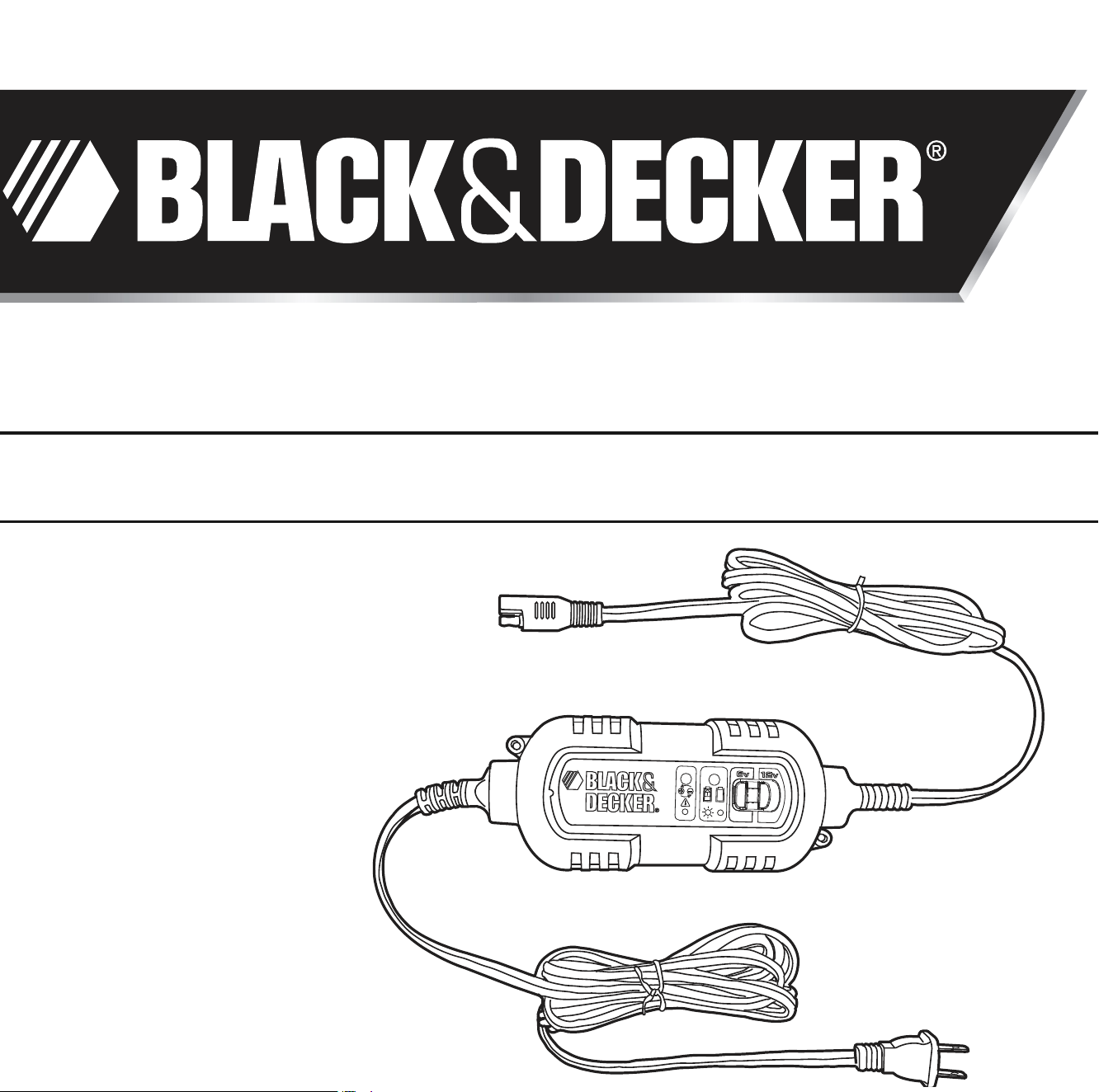
quick reference whenever the unit is used. Figure 1 shows the battery maintainer and its components.
5
This device complies with part 15 of the FCC rules. Operation is subject to the following two conditions: (1)
this device may not cause harmful interference, and (2) this device must accept any interference received,
including interference that may cause undesired operation.
This equipment has been tested and found to comply with the limits for a Class B digital device, pursuant to
part 15 of the FCC Rules. This limits are designed to provide reasonable protection against harmful interfer-
ence in a residential installation. This equipment generates, uses and can radiate radio frequency energy and,
if not installed and used in accordance with the instructions, may cause harmful interference to radio com-
munications. However, there is no guarantee that interference will not occur in a particular installation. If
equipment does cause harmful interference to radio or television reception, which can be determined by turn-
ing the equipment off and on, the user is encouraged to try to correct the interference by one or more of the
following measures:
• Reorient or relocate the receiving antenna.
• Increase the separation between equipment and receiver.
• Connect the equipment into an outlet on a circuit different from that to which the receiver is connected.
• Consult the dealer or an experienced radio/TV technician for help.
FEATURES
• The unit has two voltage rate settings (6v, 12v), controlled by one switch:
a) Use for battery maintenance, charging RVs, speciality vehicles, antique and classic cars, marine deep cycle
batteries, motorcycles, lawn mowers, tractors, ATVs, snowmobiles. personal watercraft and more.
• Maintains battery charge in stored vehicles
• Includes three connector sets:
a) DC accessory plug
b) Battery harness clips
c) Battery ring terminal harness
• Charging indicators:
a) Red – bad connection, battery not able to accept charge, reverse polarity hook-up
b) Blinking Green – connection correct and charging
c) Solid Green – fully charged
• ETL-Listed for safety
• Fully automatic; powers on when needed, powers off when battery is fully-charged or topped-off
• Built-in circuit protection guards against overcharging or short circuit
• Automatically checks for correct polarity (requires a minimum of 2.0 volts battery voltage)
• Convenient, color-coded ring terminals/clamps for easy, correct installation
• Charges with high frequency, pure, DC current
Mounting Instructions:
BM3B battery maintainer is designed to be able to mount to flat surface.
The unit has incorporated two mounting holes at the corners of the unit.
Note: Always disconnect the maintainer at AC power source and at battery terminal when mounting the unit.
To mount the unit:
1. Make sure the surface is flat and free of obstruction so the unit can rest flat on the surface.
2. Make sure the unit is disconnected from both AC power source and the battery.
3. Use 8/32 inches (6.35mm) wood screw to mount the unit through the mounting hole.
4. Do not over tighten the screw, it will damage the housing.
5. Connect the unit to AC power outlet and the unit is ready for use.
WARNING:Do not put the screw through the plastic housing as this will permanently damage the unit and cause
potential electrical hazard.
OPERATING INSTRUCTIONS
Ensure that all installation and operating instructions and safety precautions are understood and carefully followed by
anyone installing or using the charger. Follow the steps outlined in “Important Safety Instructions” at the front of this
manual.
6
BATTERY TERMINAL RINGS
DC ACCESSORY PLUG
6V/12V BATTERY MAINTAINER
BATTERY TERMINAL CLAMPS
1
110/120 VOLT
AC PLUG END
6 VOLT / 12 VOLT SWITCH
Charger Connector
Charging Indicators
Red LED – Bad connection, reverse polarity
connection; check that the RED clamp is connected to + battery terminal.
Blinking Green LED – Connection correct and charging
Solid Green LED – Battery fully charged
When the charger is properly connected, the LED will illuminate, indicating the inside smart circuit is functioning to
judge the battery status. This procedure may take up to 2 minutes if battery voltage is lower than 12.8 volts.
Setting the Voltage
The unit has two voltage rate settings (6v, 12v), controlled by one switch. Set the switch to either 6v or 12v
depending upon the battery you are charging.
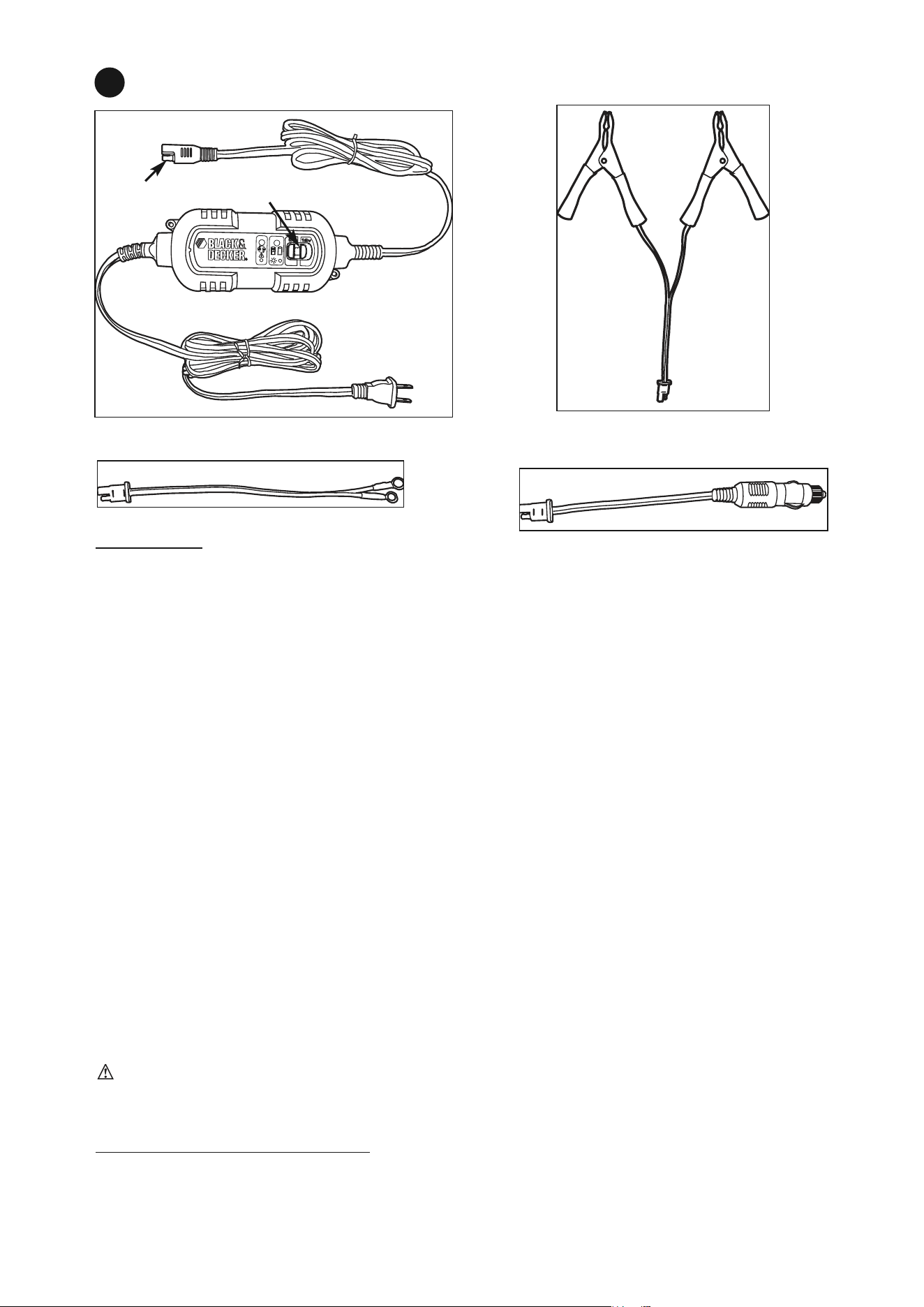
Connecting the Charger with the Terminal Clamps
The charger’s output leads have color-coded battery clamps (Figure 2) (RED-POSITIVE and
BLACK-NEGATIVE).
1. Disconnect battery and remove the battery from vehicle.
2. Unplug the battery maintainer AC cord from the AC outlet.
3. Disconnect the battery clamps from the unit at output cord connector.
4. Connect the RED POSITIVE clamp to the POSITIVE post of the battery.
5. Connect the BLACK NEGATIVE clamp to the NEGATIVE post of the battery.
6. Connect the battery clamp connector with the unit connector, as far away from the battery
as possible.
7. Slide the voltage selector to proper setting and plug the AC cord to AC outlet
8. Observe blinking GREEN LED, indicates unit is operating.
9. Monitor the unit periodically.
WARNING: FOLLOW THE STEPS OUTLINED IN "IMPORTANT SAFETY INSTRUCTIONS" AT THE FRONT OF THIS MAN-
UAL AND THE WARNING AT THE BOTTOM OF PAGE 4, "TO REDUCE RISK OF A SPARK NEAR THE BATTERY"
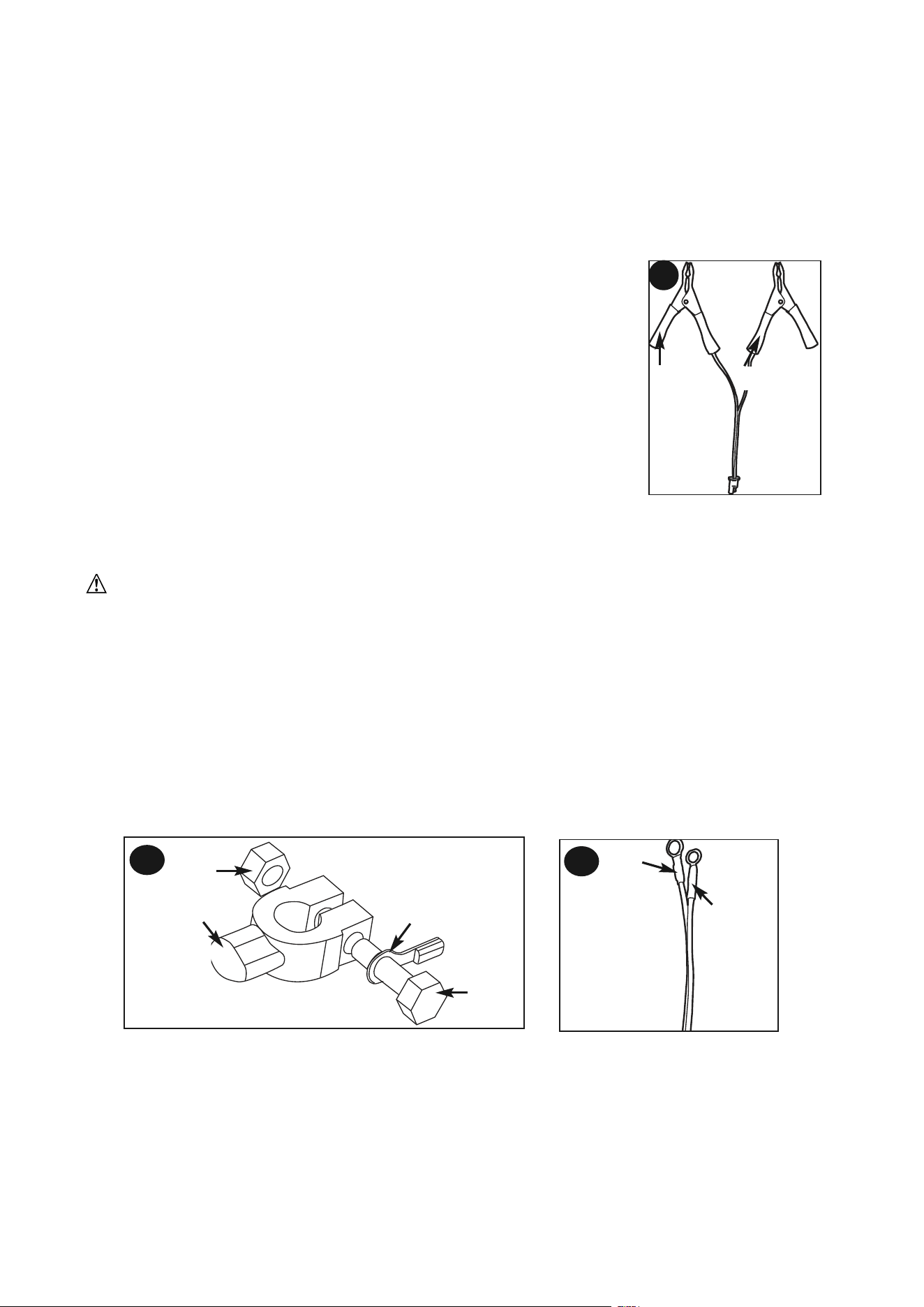
Connecting the Charger with Terminal Rings
The charger’s output leads have crimped, color-coded ring terminals (Figure 3) (RED-POSITIVE and BLACK-NEGATIVE).
These rings connect directly to the corresponding connectors on the battery posts.
1. Remove the nuts from the bolts of the battery post’s connectors.
2. Position the RED terminal on the bolt of the POSITIVE battery post connector.
3. Position the BLACK terminal on the NEGATIVE post connector; then replace the nuts.
4. If there is any problem connecting the output leads, check with a reputable auto supply store or contact the
Customer Service Department toll-free at (800) 544-6986 for assistance in finding an appropriate connection device
for your particular application.
Charging With Ring Terminals
1. Disconnect AC power cord from AC power outlet
2. Disconnect battery terminal clamps and DC accessory plug from the maintainer output cable, at connector
3. With the ring terminals connected (fig. 3a) and with ring terminal connector held as far away from battery, connect to the
maintainer output cord. If the maintainer red LED is lit, check ring terminal connections at battery.
4. Slide the voltage selector switch to 6V or 12V
5. Connect AC power
6. The unit should be working with blinking green LED, indicating the battery is being charged.
RED BLACK
2
7
RED
BLACK
CONNECTOR
NUT
BOLT
TERMINAL RINGS
3a
3b
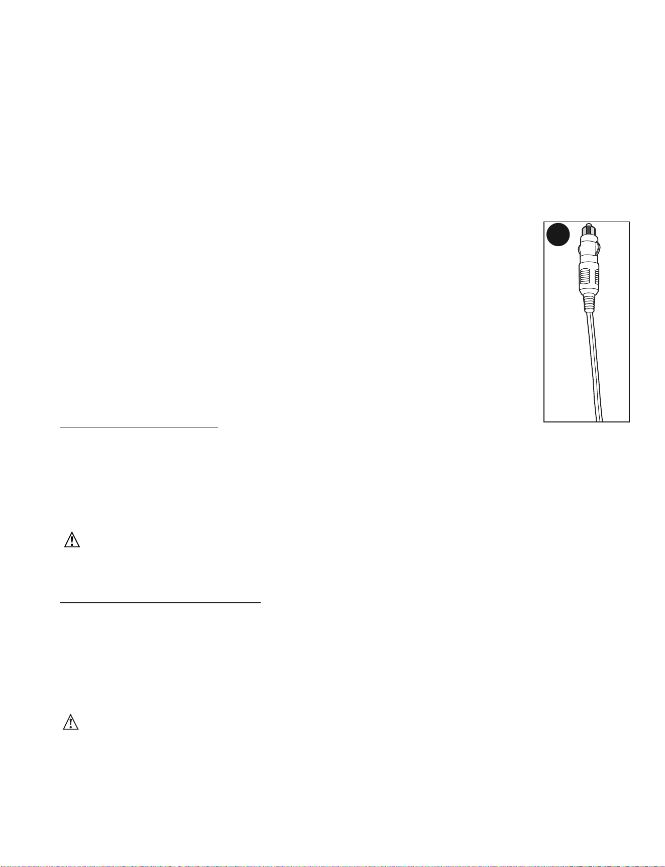
Connecting the Maintainer and Maintaining the Battery with the DC Accessory Plug
The charger’s output leads also contain a DC accessory plug (Figure 4).
Note: ALWAYS disconnect the AC power cord from the AC power outlet before connecting (or
disconnecting) the charger to (or from) the battery.
1. Slide the Voltage Selector switch to 6v or 12v.
2. Insert the DC plug into the vehicle’s DC accessory outlet.
3. Insert the AC plug of the charger into any standard 110/120 volt AC wall outlet.
Note: Some vehicles require that the ignition be turned to the ACC (accessory) position to activate the DC accessory
outlet. If your vehicle ignition is required to be turned to the ACC
position, be sure all the vehicle accessories (i.e. heater, fan, radio, TV, lights... etc) are turned off. If not turned
off, the maintainer might not be able to maintain the battery.
Charging the Battery
1. Leave the unit on.
2. Monitor the battery from time to time.
Fuse Replacement (DC Accessory Adapter)
1. Disconnect AC power from the outlet and disconnect adaptor from the output cord.
2. Remove plug from accessory outlet. Remove the plastic cap by turning counter clockwise and
lifting off.
3. Remove center pin and spring. Remove fuse.
4. Replace fuse with same type and size fuse (5 amp).
5. Replace center pin and spring inside plug.
6. Replace the plastic cap by turning clockwise.
TROUBLESHOOTING
Unit Not Charging
• Check that the charger is properly connected to a live 120 volt AC outlet (the LED will illuminate).
• Check that the correct voltage setting has been selected for the battery being maintained.
• If the battery to be maintained has fallen below 2 volts, the battery cannot be recharged with this unit.
- Make sure output connection are secured.
- Check correct polarity connections.
- If the maintainer does not detect battery voltage, the unit will not run.
WARNING: During troubleshooting, if there is a need to connect/disconnect the unit from battery, follow the
steps outlined in “Important Safety Instructions” at the front of this manual and the warning on page 4 and 5, "To
reduce risk of a spark near the battery".
CARE AND MAINTENANCE
With proper care and minimal maintenance, the Automatic Battery Maintainer will provide years of dependable
service. For maximum performance, manufacturer recommends:
1. Storing the unit in a clean, dry, cool place when not in use.
2. Cleaning the unit casing and cords (as necessary) with a dry (or slightly damp) cloth. Ensure that unit is
completely disconnected from battery and power source, before cleaning.
3. To maintain the operating condition and maximize the life of the charger cords, always coil them loosely for
storage. Do not wrap them around the unit or crimp them with a tight band.
WARNINGS:
• Do not use charger if cords have been damaged in any way — call Technical Support toll-free at (800) 544-6986.
• There are no user-serviceable parts in this unit.
• Do not open the unit. In the event of malfunction, it must be returned to manufacturer for professional testing and
repair. Opening the unit will void the manufacturer’s warranty.
4