1 PB
Service/ Parts Manual
Floating Air Select
96621400_00
FSHW091 - 9,000 BTU Single Zone - 110V
FSHW121 - 12,000 BTU Single Zone - 110V
FSHW183 - 18,000 BTU Single Zone - 230V
FSHW243 - 24,000 BTU Single Zone - 230V
FSHW363 - 36,000 BTU Single Zone - 230V

2 PB
TABLE OF CONTENTS
INTRODUCTION‑ 4
Important Safety Information‑ 4
Personal injury or death hazards‑ 6
Model identification guide‑ 7
Indoor Units‑ 8
Outdoor Units‑ 9
Remote Control‑ 9
SPECIFICATIONS‑ 10
Product Specifications‑ 10
Capacities and selection data‑ 14
9‑12K Operation Characteristics curve‑ 18
18‑24kK Operation Characteristics curve‑ 18
36K Operation Characteristics curve‑ 19
9‑12K Capacity Variation Ratio According to Temperature‑ 20
18‑24 K Capacity Variation Ratio According to Temperature‑ 20
36K Capacity Variation Ratio According to Temperature‑ 21
9‑12K Noise Curve‑ 21
18‑24K Noise Curve‑ 22
36K Noise Curve‑ 22
Cooling Data Sheet in Rated Frequency‑ 23
Heating Data Sheet in Rated Frequency‑ 23
18‑24K Indoor Unit Dimensions‑ 25
9‑12K Outdoor Unit Dimensions‑ 26
18‑24K Outdoor Unit Dimensions‑ 27
36K Outdoor Unit Dimensions‑ 27
OPERATION‑ 28
Remote Control Button Identification‑ 28
Remote Control Description‑ 29
9‑24k Sequence of Operation‑ 33
36k Sequence of Operation‑ 42
9‑12K Refrigerant System Diagram‑ 45
18‑24K Refrigerant System Diagram‑ 45
36K Refrigerant System Diagram‑ 46
INSTALLATION‑ 47
Installation Tools‑ 48
Installation Parts Checklist‑ 51
Selection of Installation Location‑ 51
Installation of Indoor Unit‑ 53
Leak Check, Evacuation, and Charging (Triple Evacuation)‑ 60
Checklist and Operation Test‑ 62
Check Unit following Installation‑ 62
Test Operation‑ 62
REMOVAL‑ 63
Indoor Unit‑ 63
Outdoor Unit‑ 68
WIRED CONTROLLER‑ 72
Display‑ 72
Buttons‑ 74
Operation Instructions‑ 75
Installation Instructions‑ 93
R‑410A SEALED SYSTEM REPAIR‑ 98
Service Valves Appearance‑ 98
Pumping Down‑ 99
Gas Charging (After Repair)‑ 100
COMPONENTS TESTING ‑ 101
Resistance Table of Ambient Temperature Sensor for Indoor and Outdoor Units (15kΩ)‑ 101
Resistance Table of Ambient Temperature Sensor for Indoor and Outdoor Units (20kΩ)‑ 102
Resistance Table of Ambient Temperature Sensor for Indoor and Outdoor Units (50kΩ)‑ 103
9‑12k Indoor Unit Printed Circuit Board Identification‑ 104
18‑24k Indoor Unit Printed Circuit Board Identification‑ 105
36k Indoor Unit Printed Circuit Board Identification‑ 106
9‑12k Outdoor Unit Printed Circuit Board Identification‑ 107
18‑24k Outdoor Unit Printed Circuit Board Identification‑ 108
36k Outdoor Unit Printed Circuit Board Identification‑ 109
TROUBLESHOOTING‑ 110
Diagnostic Codes‑ 110
Malfunction of Temperature Sensor F1, F2‑ 118
9‑12k Malfunction of blocked Protection of IDU Fan Motor H6‑ 119
18‑36k Malfunction of blocked Protection of IDU Fan Motor H6‑ 120
Malfunction of Protection of Jumper Cap C5‑ 121

3 PB
TABLE OF CONTENTS
Malfunction of IDU Fan Motor U8‑ 122
Malfunction of Communication E6 ‑ 124
Malfunction of Power Supply from Indoor to Outdoor Unit‑ 125
Malfunction of Detecting Plate (WIFI) JF‑ 126
Indoor fan does not rotate and there is no Feedback‑ 127
Temperature sensor malfunction‑ 128
Malfunction diagnosis of startup failure‑ 129
Diagnosis of losing synchronism for compressor ‑ 130
9‑12k, 36k Diagnosis of overload and discharge malfunction‑ 131
18‑24k Diagnosis of overload and discharge malfunction‑ 132
Capacity Charging malfunction ‑ Outdoor unit‑ 133
9‑24k PM protection, phase current overcurrent ‑ 134
36k IPM Protection, Out‑of‑Step Fault, Compressor Phase Overcurrent‑ 135
High temperature and Overload Protection Diagnosis‑ 136
PFC (Correction Power Factor) Outdor Unit Malfuction‑ 137
Communication malfunction: (following AP1 for outdoor unit control board)‑ 138
High‑pressure Protection‑ 139
Troubleshooting for Malfunction without Active Error Code‑ 140
WIRING DIAGRAMS‑ 143
9‑12K Indoor Unit Wiring Diagram ‑ 143
18‑24k Indoor Unit Wiring Diagram‑ 144
36K Indoor Unit Wiring Diagrams ‑ 145
18‑24k Outdoor Unit Wiring Diagrams‑ 147
36k Outdoor Unit Wiring Diagrams‑ 147
PARTS CATALOG‑ 148
9K Indoor Unit ‑ 148
12k Indoor Unit‑ 150
18K Indoor Unit‑ 152
24K Indoor Unit‑ 154
36K Indoor Unit‑ 156
9K Outdoor Unit‑ 158
12k Outdoor Unit‑ 160
18k Outdoor Unit‑ 162
24k Outdoor Unit‑ 164
36k Outdoor Unit‑ 166
APPENDIX‑ 168
Appendix 1: Reference Sheet of Celsius and Farenheit‑ 168
Appendix 2: Configuration of Connection Pipe‑ 168
Appendix 3: Pipe Expanding Method‑ 169
LIMITED WARRANTY‑ 170
FRIEDRICH AUTHORIZED PARTS DEPOTS‑ 171
4 PB
INTRODUCTION
The information in this manual is intended for use by a qualified technician who is familiar with the safety procedures
required for installation and repair, and who is equipped with the proper tools and test instruments required to service
this product.
Installation or repairs made by unqualified persons can result in subjecting the unqualified person making such repairs
as well as the persons being served by the equipment to hazards resulting in injury or electrical shock which can be
serious or even fatal.
Safety warnings have been placed throughout this manual to alert you to potential hazards that may be encountered. If
you install or perform service on equipment, it is your responsibility to read and obey these warnings to guard against
any bodily injury or property damage which may result to you or others.
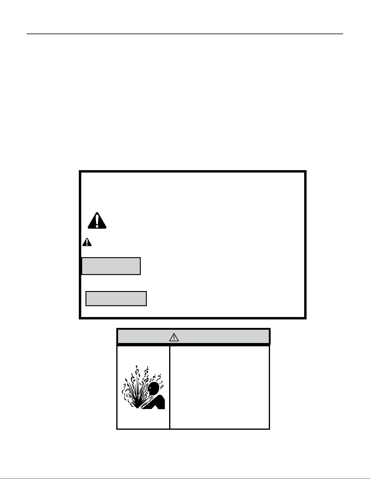
Important Safety Information
Your safety and the safety of others is very
important.
We have provided many important safety messages in this manual and on your appliance. Always read
and obey all safety messages.
This is a safety Alert symbol.
This symbol alerts you to potential hazards that can kill or hurt you and others.
All safety messages will follow the safety alert symbol with the word “WARNING”
or “CAUTION”. These words mean:
Indicates a hazard which, if not avoided, can result in severe personal
injury or death and damage to product or other property.
Indicates a hazard which, if not avoided, can result in personal injury and
damage to product or other property.
All safety messages will tell you what the potential hazard is, tell you how to reduce the chance of
injury, and tell you what will happen if the instructions are not followed.
Indicates property damage can occur if instructions are not followed.
WARNING
NOTICE
CAUTION
WARNING
Refrigeration system
under high pressure
Do not puncture, heat, expose to flame or
incinerate.
Only certified refrigeration technicians should
service this equipment.
R410A systems operate at higher pressures
than R22 equipment. Appropriate safe service
and handling practices must be used.
Only use gauge sets designed for use with
R410A.
Do not use standard R22 gauge sets.
5 PB
Important Safety Information
INTRODUCTION
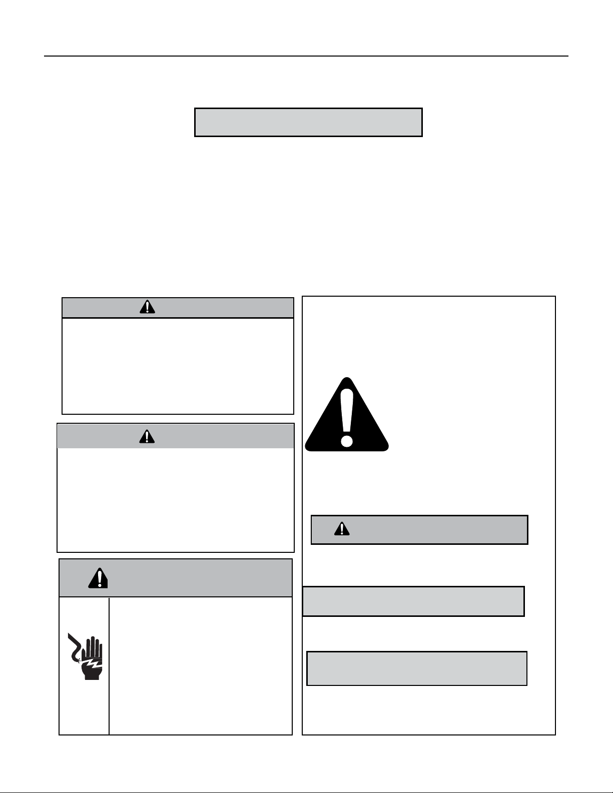
WARNING
Please read this manual thoroughly prior to equipment
installation or operation. It is the installer’s responsibility
to properly apply and install the equipment. Installation
must be in conformance with the NFPA 70-2008 National
Electric Code or current edition, International Mechanic
code 2009 or current edition and any other applicable
local
or national codes.
WARNING
Refrigeration system under high pressure. Do not punc-
ture, heat, expose to ame or incinerate. Only certied
refrigeration technicians should service this equipment.
R410A systems operate at higher pressures than R22
equipment. Appropriate safe service and handling prac-
tices must be used. Only use gauge sets designed for use
with R410A. Do not use R22 gauge sets. Failure to do so
can result in property damage, personal injury, or death.
WARNING
Electrical shock hazard.
Turn OFF electric power before service or installation.
Unit must be properly grounded.
Unit must have correct fuse or circuit breaker protec‑
tion. Unit’s supply circuit must have the correct
wire conductor size. All electrical connections and
wiring must be installed by a qualified electrician and
conform to the National Electrical Code and all local
codes which have jurisdiction. Failure to do so can
result in property
damage, personal injury and/or death.
Your safety and the safety of others are very
important.
We have provided many important safety messages in
this manual and on your appliance. Always read and
obey all safety messages.
This is the safety Alert symbol.
This symbol alerts you to potential
hazards that can kill or hurt you
and others.
All safety messages will follow the
safety alert symbol with the word
“WARNING” or “CAUTION”.
These words mean:
Indicates a hazard which, if not avoided, can result in
severe personal injury or death and damage to product or
other property.
Indicates a hazard which, if not avoided, can result in
personal injury and damage to product or other property.
All safety messages will tell you how to reduce the chance
of injury, and tell you what will happen if the instructions
are not followed.
Indicates property damage can occur if instructions
are not followed.
WARNING
CAUTION
NOTICE
DO NOT OPERATE EQUIPMENT DURING ACTIVE STAGES OF CONSTRUCTION
To ensure proper operation, Friedrich requires that all equipment is not operated during active construction phases. This includes active stages of
completing framing, drywalling, spackling, sanding, painting, flooring, and moulding in the equipment’s designated conditioning space. The use of this
equipment during construction could result in premature failure of the components and/or system and is in violation of our standard warranty guide‑
lines. The operation of newly installed equipment during construction will accelerate the commencement and/or termination of the warranty period.
CAUTION
6 PB
INTRODUCTION
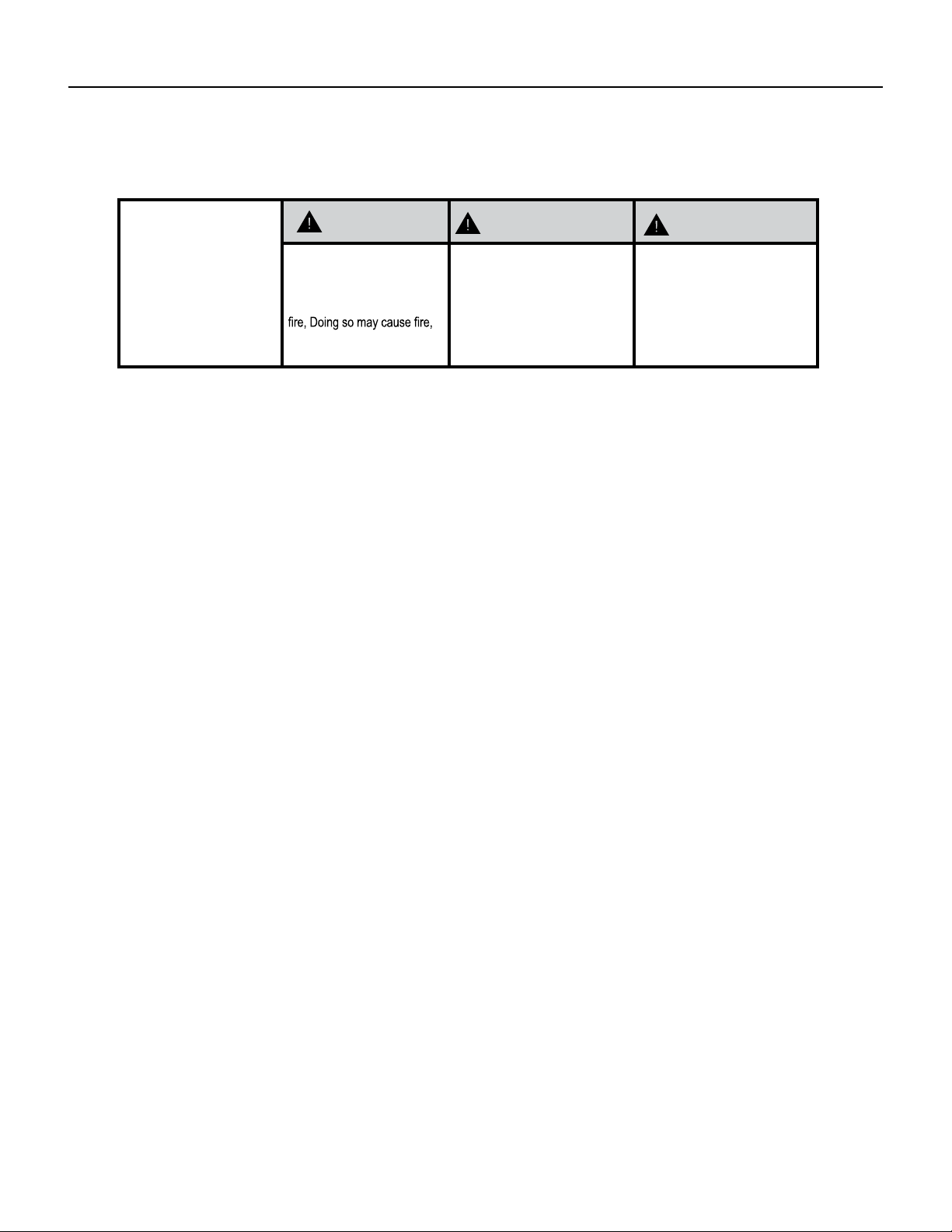
Personal injury or death hazards
SAFETY
FIRST
WARNING
AVERTISSEMENT ADVERTENCIA
Do not remove, disable or
bypass this unit’s safety
devices. Doing so may cause
injuries, or death.
Ne pas supprime, désactiver ou
contourner cette l´unité des
dispositifs de sécurité, faire vous
risqueriez de provoquer le feu, les
blessures ou la mort. o muerte.
No eliminar, desactivar o pasar
por alto los dispositivos de
seguridad de la unidad. Si lo hace
podría producirse fuego, lesiones
ELECTRICAL HAZARDS:
• Shutdown and/or disconnect all electrical power to the unit before performing inspections, maintenance, or
service.
• Make sure to follow proper lockout/tag out procedures.
• Always work in the company of a qualied assistant if possible.
• Capacitors, even when disconnected from the electrical power source, retain an electrical charge potential
capable of causing electric shock or electrocution. Wait a few minutes after shutdown to allow the capacitors to
discharge the stored energy.
• Handle, discharge, and test capacitors according to safe, established, standards, and approved procedures.
• Extreme care, proper judgment, and safety procedures must be exercised if it becomes necessary to test or
troubleshoot equipment with the power turned on to the unit.
• Do not spray water on the air conditioning unit while the power is on.
• Electrical component malfunction caused by water could result in electric shock or other electrically unsafe
conditions when the power is restored and the unit is turned on, even after the exterior is dry.
• Use air conditioner on a single dedicated circuit within the specied amperage rating.
• Ensure the unit that the unit is properly grounded.
• Do not cut or modify the power supply cord or remove the ground prong of the plug.
• Never operate the unit on an extension cord.
• Follow all safety precautions and use approved protective safety equipment such as: gloves, goggles, and
clothing. Ensure that properly insulated tools, and testing equipment are are used as well to protect against
equipment damage and reduce the risk of injury.
• Failure to follow proper safety procedures and these warnings can result in serious injury or possibly death.
7 PB
INTRODUCTION
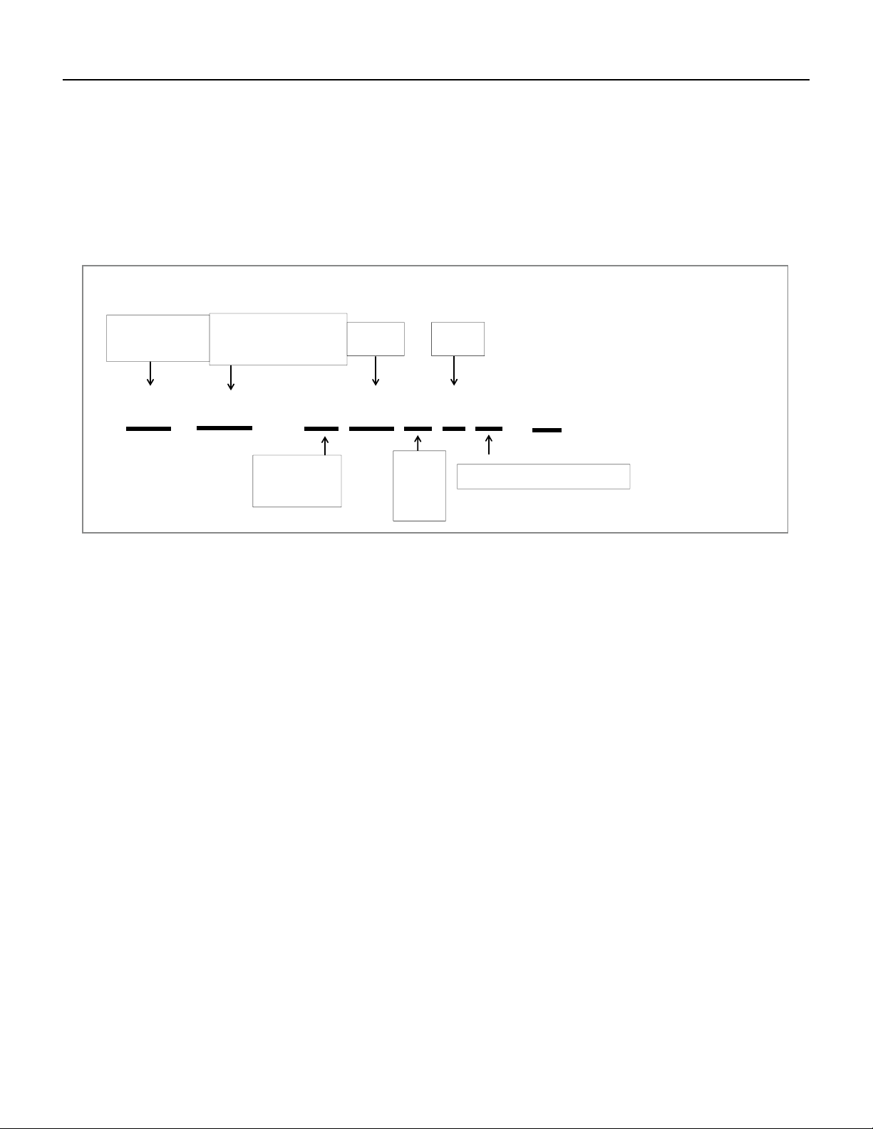
Model identification guide
FP HS W 09
A 1 A
- A
Model Type:
FR- Floating Air Premier
FP - Floating Air Pro
FS- F loating Air Select
Application :
W- Wallmounted
D- Ducted (Insider)
C- Cassette
R- Remo te Condenser
Function :
HS – H ea t Pump Single
HM – Heat Pump Multi
HF – Heat Pump F lex Single and
Multizon e
Cooling
BTU/HR
Model
Approximate
Introductory
Chara cter:
Voltag e
A- 2019
B- 202 0
C- 2021
D- 202
2
1- 115 Volts
3- 230 Volts
MODEL IDENTIFICATION GUIDE
Marketing Suffix :
Letter indicates modification to existing mode
l
Figure 101
Model Identification Guide
8 PB
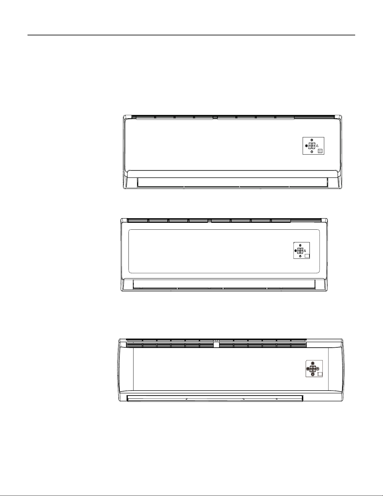
INTRODUCTION
FSHSW09A1A
FSHSW12A1A
Figure 102
Indoor Units
FSHSW18A3A
FSHSW24A3A
FSHSW36A3A
9 PB
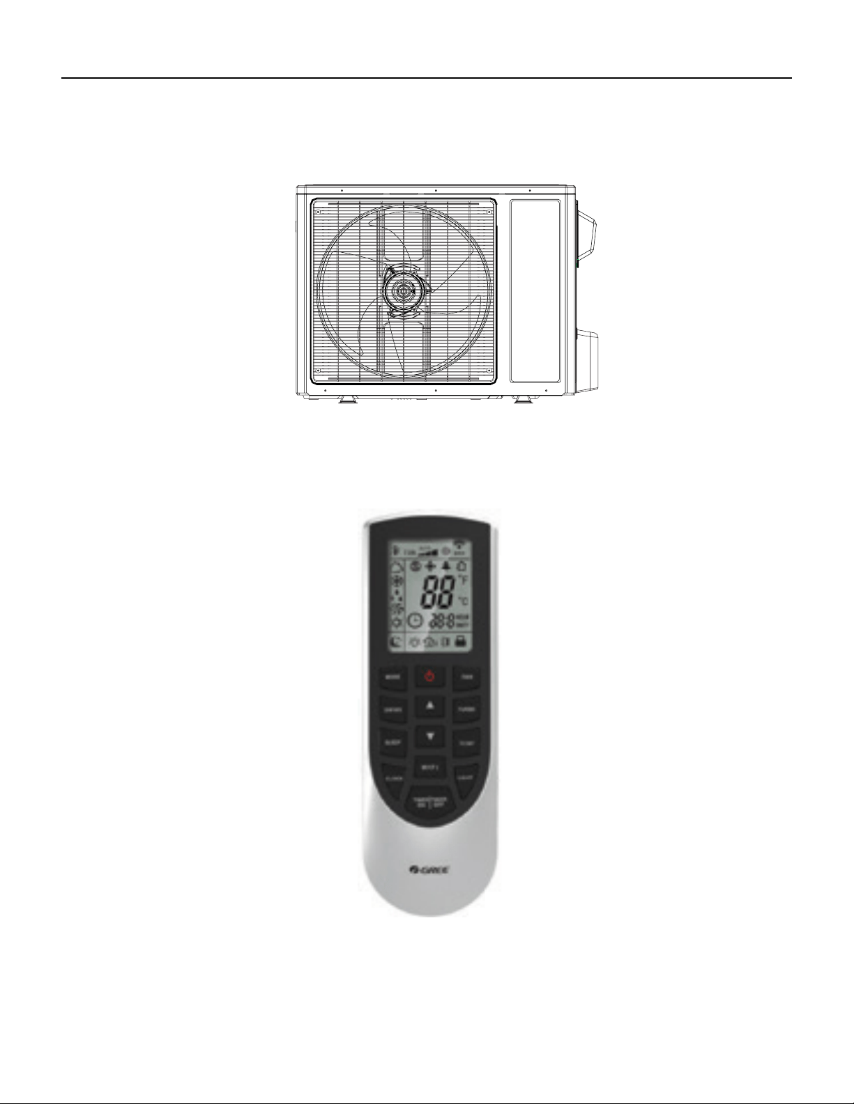
INTRODUCTION
FSHSR09A1A
FSHSR12A1A
FSHSR18A3A
FSHSR24A3A
FSHSR36A3A
Figure 103
Outdoor Units
FSHSW09A1A
FSHSW12A1A
FSHSW18A3A
FSHSW24A3A
FSHSW36A3A
Figure 104
Remote Control
10 PB
SPECIFICATIONS
Figure 201
Product Specifications
Friedrich Indoor Model Number Unit FSHSW09A1A FSHSW12A1A FSHSW18A3A FSHSW24A3A FSHSW36A3A
Friedrich Outdoor Model Number FSHSR09A1A FSHSR12A1A FSHSR18A3A FSHSR24A3A FSHSR36A3A
Friedrich Indoor UPC code 724587438710 724587438727 724587438734 724587438741 724587438758
Friedrich Outdoor UPC code 724587438765 724587438772 724587438789 724587438796 724587438802
Product Code CB425008200 CB425007900 CB425007400 CB425007700 CB432008100
Power Supply
Rated Voltage V 115 115 208/230 208/230 208/230
Rated Frequency Hz 60 60 60 60 60
Phases -- 1 1 1 1 1
Power Supply Mode Outdoor Outdoor Outdoor Outdoor Outdoor
Cross-sectional Area of Power Cable
Conductor
AWG AWG12 AWG12 AWG14 AWG14 AWG12
Recommended Power Cable(Core) N 3 3 3 3 3
Min/Max. Voltage V 103/127 103/127 187/253 187/253 187/253
Cooling Capacity W 2638 3517 5275 6450 9850
Cooling Capacity Btu/h 9000 12000 18000 22000 33600
Min. Cooling Capacity W 810 1100 1000 2500 2170
Min. Cooling Capacity Btu/h 2764 3753 3412 8600 7404.04
Max. Cooling Capacity W 2850 3664 6000 7034 10550
Max. Cooling Capacity Btu/h 9724 12500 20472 24000 35996.6
Heating Capacity W 2784 3810 5803 7034 10140
Heating Capacity Btu/h 9500 13000 19800 24000 34600
Min. Heating Capacity W 610 1000 1000 2500 4390
Min. Heating Capacity Btu/h 2081 3412 3412 8600 14978.68
Max. Heating Capacity W 3600 4400 6400 7600 10550
Max. Heating Capacity Btu/h 12283 15013 21837 26000 35996.6
Cooling Power Input W 900 1194 1820 2010 4100
Min. Cooling Power Input W 350 380 80 600 450
Max. Cooling Power Input W 1100 1300 2350 2700 4300
Heating Power Input W 870 1250 2090 2130 3800
Min. Heating Power Input W 280 350 220 650 560
Max. Heating Power Input W 1250 1350 2350 2750 4300
Cooling Current A 10.87 13 8.1 8.92 17
Heating Current A 10.36 13.5 8.5 9.45 16.5
Rated Input W 1270 1350 2350 2750 4300
Rated Current A 12.66 13.5 12 11.98 20
Rated Heating Current A 10.65 13.8 13 12.2 20
Max. Over Current Protection A 25 30 25 25 40
Min. Current (MCA) A 17 20 16 16 24
Starting Current A 6 8 / 5 2
EER W/W 2.93 2.95 2.9 3.21 2.4
EER Btu/h)/w 10 10.05 9.89 10.95 8.2
COP W/W 3.2 3.05 2.78 3.3 2.67
COP Btu/h)/w 10.92 10.4 9.47 11.3 9.11
SEER 18 18 18 18 18
HSPF 9 9 9 10 9
Air Flow Volume m3/h 540/490/ 410/290 680/540/ 410/330 850/750/ 650/500 1200/1050/ 900/750 1500/1300/ 1100 /950
Air Flow Volume CFM 318/288/241/171 400/318/241/194 500/441/383/294
706.2/617.925
/529.65/441.375
882.75/765.05/647.35
/559.075
11 PB
SPECIFICATIONS
Figure 202
Product Specifications
Friedrich Indoor Model Number Unit FSHSW09A1A FSHSW12A1A FSHSW18A3A FSHSW24A3A FSHSW36A3A
Friedrich Outdoor Model Number FSHSR09A1A FSHSR12A1A FSHSR18A3A FSHSR24A3A FSHSR36A3A
Dehumidifying Volume L/h 0.8 1.4 1.8 2 3.5
Dehumidifying Volume PINT/D 1.69 2.96 3.8 4.23 7.4
Application Area sq ft 130-194 172-258 248-366 248-366 495-764
Indoor unit
Fan Type ‑‑ Cross‑flow Cross‑flow Cross‑flow Cross‑flow Cross‑flow
Fan Diameter
Length(D×L)
inch 3 6/7×22 5/6 3 6/7×25 / 4 1/4×32 7/10 4 1/4 × 20 4/7
Cooling Speed r/min 1350/1200/1050/750 1350/1200/1000/800 1350/1200/1050/900 1300/1150/1000/850 1400/1250/1000/800
Heating Speed r/min 1350/1200/1050/850 1350/1200/1000/900 1300/1200/1100/900 1300/1150/1000/850 1400/1250/1050/850
Fan Motor Power
Output
W 20 20 35 30 70
Fan Motor RLA A 0.24 0.25 0.37 0.32 0.4
Fan Motor Capacitor μF 4 4 2.5 3 0
Evaporator Form --
Aluminum Fin-copper
Tube
Aluminum Fin-copper
Tube
Aluminum Fin-copper
Tube
Aluminum Fin-copper
Tube
Aluminum Fin-copper
Tube
Evaporator Pipe
Diameter
inch 0.197 0.197 / / 2/7
Evaporator Row-n
Gap
inch 2-1/18 2-1/18 / / 2-1/18
Evaporator Coil
Length (L×D×W)
inch 23×7/8×10 8/16 25×7/8×12 1/16 / 33 1/4×1×13 1/2 42 2/7×1×15
Swing Motor Model -- MP24AA MP24BA MP35CJ MP35CJ MP24BA
Swing Motor Power
Output
W 1.5 1.5 2.5 2.5 1.5
Fuse Current A 3.15 3.15 3.15 3.15 3.15
Set Temperature
Range
°F 61-86 61-86 61-86 61-86 61-86
Sound Pressure
Level
dB (A) 43/38/34/28 43/39/35/29 47/44/41/35 49/46/42/36 54/49/44/37
Sound Power Level dB (A) 53/48/44/28 53/49/45/39 57/54/51/45 63/59/56/52 64/59/54/47
Dimension (W×H×D) inch 31.102×10.827×7.874 33.268×11.378×8.228 38.2×11.8×8.8 42.441×12.795×9.685 53.15×12.835×9.961
Net Weight lb 20.9 23.2 30.9 37.485 41.895
Gross Weight lb 25.4 27.6 37.5 45.202 51.818
12 PB
SPECIFICATIONS
Friedrich Indoor Model Number Unit FSHSW09A1A FSHSW12A1A FSHSW18A3A FSHSW24A3A FSHSW36A3A
Friedrich Outdoor Model Number FSHSR09A1A FSHSR12A1A FSHSR18A3A FSHSR24A3A FSHSR36A3A
Outdoor Unit
Compressor Manufacturer
ZHUHAI LANDA COM-
PRESSOR CO.,LTD
ZHUHAI LANDA COM-
PRESSOR CO.,LTD
ZHUHAI LANDA COM-
PRESSOR CO.,LTD
ZHUHAI LANDA COM-
PRESSOR CO.,LTD
ZHUHAI LANDA COM-
PRESSOR CO., LTD
Compressor Model QXA-A091zE190 QXA-A091zE190 QXA-B141zF030A QXA-B141zF030A QXAS-D32ZX090A
Compressor Oil FVC68D or RB 68EP FVC68D or RB 68EP RB68EP RB68EP RB68EP or equivalent
Compressor Type Rotary Rotary Rotary Rotary Rotary
Compressor LRA. A 40 40 25 25 67
Compressor RLA A 12.62 15.23 12.08 12.18 17.5
Compressor Power
Input
W 980 980 1440 1440 4150±3%
Compressor Overload Protector
1NT11L-6233
or KSD115 or
HPC115/95U1
1NT11L-6233
or KSD115 or
HPC115/95U1
/ / 1NT11L-6233
Fan Type Axial-ow Axial-ow Axial-ow Axial-ow Axial-ow
Fan Diameter inch 15.748 15.748 / 20 21.654
Fan Motor Speed rpm 850 900 800 800 890
Fan Motor Power
Output
W 30 30 60 60 170
Fan Motor RLA A 0.24 0.23 0.52 0.4 0.73
Outdoor Unit Air
Flow Volume
m3/h 1800 1800 3200 3200 4400
Condenser Form
Aluminum Fin-copper
Tube
Aluminum Fin-copper
Tube
Aluminum Fin-copper
Tube
Aluminum Fin-copper
Tube
Aluminum Fin-copper
Tube
Condenser Pipe
diameter
inch 0.276 0.276 / / φ3/8
Condenser Rows-n
Gap
mm 1-1.4 2-1.4 1-1.4 2-1.4 2-1.4
Condenser Rows-n
Gap
inch 1-1/18 2-1/18 / / 2-1/18
Condenser Coil
Length (L×D×W)
inch 29 3/4×3/4×20 28×1 1/2×20 / / 37×1 3/4×30
Permissible Excessive
Operating Pressure for
the Discharge Side
MPa 4.3 4.3 4.3 4.3 4.3
Permissible Exces-
sive Operating
Pressure for the
Suction Side
MPa 2.5 2.5 2.5 2.5 2.5
Maximum Allowable
Pressure
MPa 4.3 4.3 4.3 4.3 4.3
Cooling Operation
Ambient Tempera-
ture Range
°F 0~115 0~115 0φ115 0~115 0~115
13 PB
SPECIFICATIONS
Friedrich Indoor Model Number Unit FSHSW09A1A FSHSW12A1A FSHSW18A3A FSHSW24A3A FSHSW36A3A
Friedrich Outdoor Model Number FSHSR09A1A FSHSR12A1A FSHSR18A3A FSHSR24A3A FSHSR36A3A
Outdoor Unit
Heating Operation
Ambient Tempera-
ture Range
°F -4~75 -4~75 -13φ75 -13φ75 -4φ75
Throttling Method
Electron expansion
valve
Electron expansion
valve
Electron expansion
valve
Electron expansion
valve
Electron expansion
valve
Defrosting Method Automatic Defrosting Automatic Defrosting Automatic Defrosting / Automatic Defrosting
Climate Type T1 T1 T1 T1 T1
Climate Zone Temperate Zone Temperate Zone Temperate Zone Frigd Zone Temperate Zone
Isolation I I I I I
Moisture Protection IPX4 IPX4 IPX4 IPX4 IPX4
Sound Pressure
Level
dB (A) 52 53 57 58 65
Sound Power Level dB (A) 62 63 67 68 75
Dimension (W×H×D) inch 33.386×21.26×12.598 33.386×21.26×12.598 37.6×27.6×15.6 37.598×27.559×15.591 38.583×31.102×16.811
Net Weight lb 62.8 67.3 97 103.635 160.965
Gross Weight lb 68.4 72.8 106.9 113.558 171.99
Refrigerant R410A R410A R410A R410A R410A
Refrigerant Charge oz 24.7 31.8 45.86 56.4 91.71
Length ft 24.6 24.6 24.6 24.6 24.6
Gas Additional
Charge
oz/ft. 0.2 0.2 0.2 0.538 0.538
Outer Diameter of
Liquid Pipe(British
System Allocation)
inch 1/4" 1/4" 1/4" 1/4" 1/4"
Outer Diameter of
Gas Pipe(British
System Allocation)
inch 3/8" 3/8" 1/2" 5/8" 5/8"
Max Distance Height ft 32.8 49.2 65 65.6 32.8
Max Distance Length ft 65.6 98.4 100 100.1 98.4

14 PB
SPECIFICATIONS
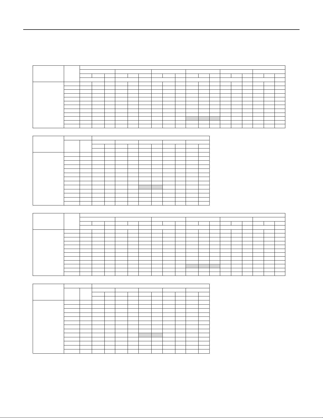
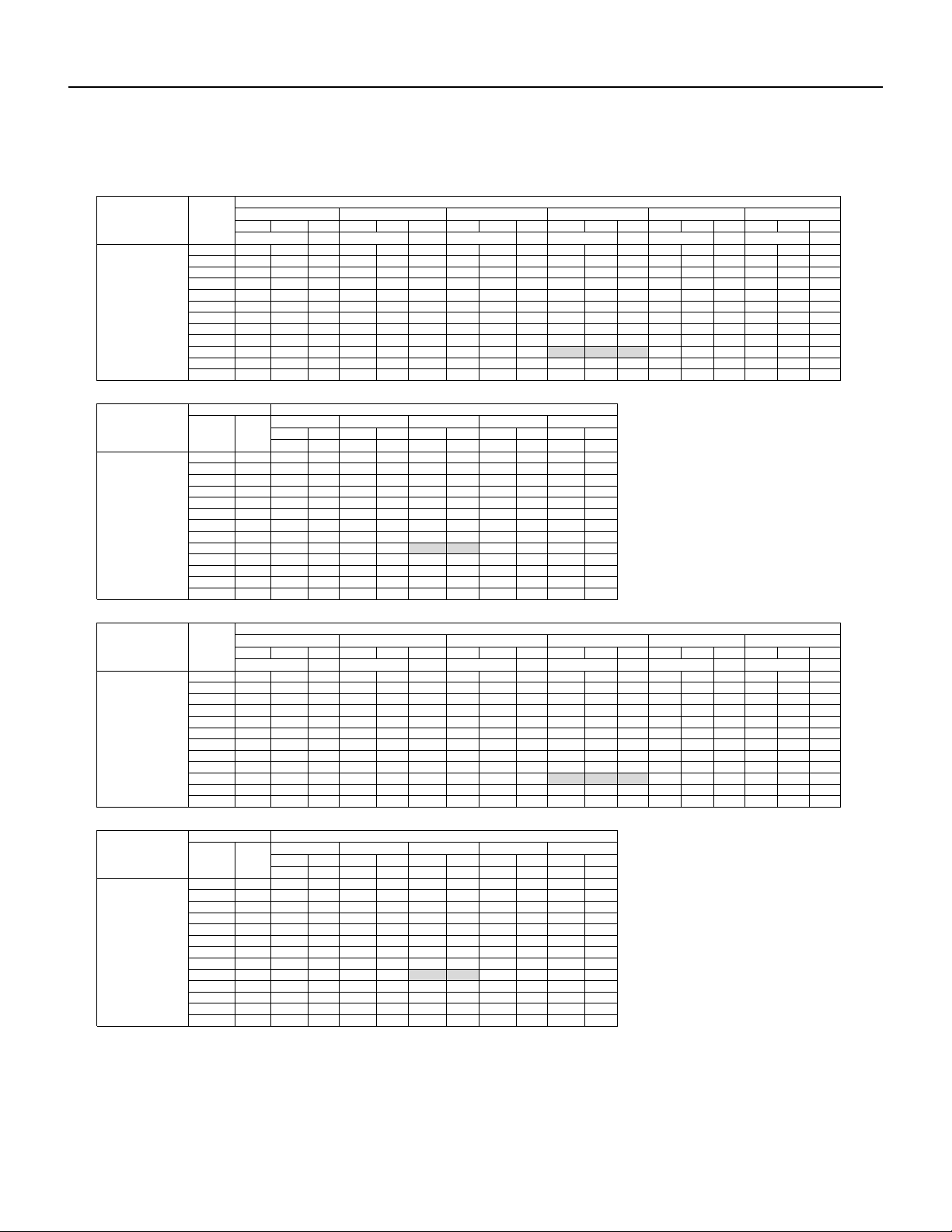
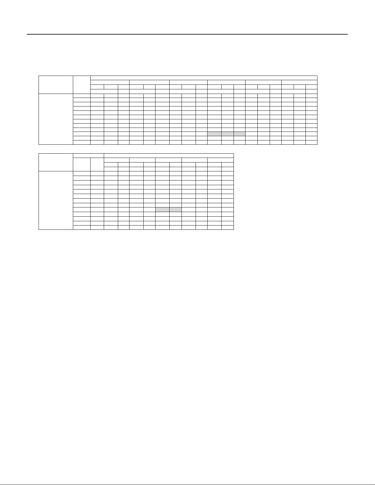
Capacities and selection data
Capacity characteristic charts
The following charts show the characteristics of outdoor unit capacity, which corresponds with
the operating ambient temperature of outdoor unit. This data is obtained with Free-Spin of the
Condenser and not in a testing mode
Conditions:
1
Capacities and selection data
1- Pipe length / height difference : 25 ft. (7.6m) / 0 ft. (0m)
2- Compressor at rated inverter frequency
3- Indoor fan speed at high fan speed
4- Capacity loss due to frost accumulation and defrost
operation is not included.
15 PB
SPECIFICATIONS
Capacities and selection data
Cooling Template
TC SHC PI TC SHC PI TC SHC PI TC SHC PI TC SHC PI TC SHC PI
kW kW kW kW kW kW
14 3.83 2.81 0.60 4.55 3.34 0.63 4.86 3.57 0.65 5.22 3.84 0.67 5.40 3.97 0.68 4.95 3.64 0.68
23 4.19 3.10 0.63 4.91 3.63 0.66 5.22 3.86 0.67 5.58 4.13 0.69 5.76 4.26 0.70 5.31 3.93 0.71
32 4.37 3.25 0.65 5.09 3.79 0.68 5.40 4.02 0.70 5.76 4.29 0.72 5.94 4.43 0.73 5.49 4.09 0.74
41 4.91 3.68 0.67 5.63 4.22 0.71 5.94 4.46 0.72 6.30 4.73 0.75 6.48 4.86 0.76 6.03 4.52 0.77
50 5.45 4.11 0.70 6.17 4.65 0.74 6.48 4.89 0.75 6.84 5.16 0.77 7.02 5.30 0.78 6.57 4.96 0.79
59 5.90 4.48 0.72 6.62 5.03 0.76 6.93 5.27 0.78 7.29 5.54 0.80 7.47 5.68 0.81 7.02 5.34 0.82
67 6.08 4.65 0.75 6.80 5.20 0.79 7.11 5.44 0.80 7.47 5.71 0.83 7.65 5.85 0.84 7.20 5.51 0.85
77 7.97 6.13 0.77 8.69 6.69 0.81 9.00 6.93 0.83 9.36 7.21 0.86 9.54 7.35 0.86 9.09 7.00 0.87
87 8.42 6.52 0.80 9.14 7.08 0.84 9.45 7.32 0.86 9.81 7.60 0.88 9.99 7.74 0.89 9.54 7.39 0.90
95 7.61 5.93 0.81 8.33 6.49 0.86 8.64 6.74 0.87 9.00 7.02 0.90 9.18 7.16 0.91 8.73 6.81 0.92
104 6.66 5.23 0.89 7.38 5.79 0.94 7.74 6.08 0.96 8.10 6.36 0.99 8.28 6.50 1.00 7.83 6.15 1.01
115 6.300 4.977 0.975 7.020 5.546 1.026 7.380 5.830 1.048 7.740 6.115 1.080 7.920 6.257 1.089 7.470 5.901 1.098
Heating Template
TC PI TC PI TC PI TC PI TC PI
kBtu/h kW kBtu/h kW kBtu/h kW kBtu/h kW kBtu/h kW
-15 -17 3.61 0.67 3.71 0.68 3.99 0.70 4.09 0.71 4.13 0.71
-5 -7 4.18 0.68 4.28 0.69 4.56 0.71 4.66 0.73 4.70 0.73
5 3 5.13 0.71 5.23 0.72 5.51 0.74 5.61 0.75 5.65 0.76
10 8 5.32 0.73 5.42 0.73 5.70 0.76 5.80 0.77 5.84 0.77
14 12 5.80 0.74 5.89 0.75 6.18 0.77 6.27 0.79 6.32 0.79
23 19 7.32 0.77 7.41 0.78 7.70 0.80 7.79 0.82 7.84 0.82
32 28 7.98 0.79 8.08 0.79 8.36 0.82 8.46 0.84 8.50 0.84
41 37 8.65 0.80 8.74 0.81 9.03 0.84 9.12 0.85 9.17 0.86
47 43 9.12 0.84 9.22 0.84 9.50 0.87 9.60 0.89 9.64 0.89
50 47 9.22 0.86 9.31 0.87 9.60 0.90 9.69 0.91 9.74 0.92
59 50 9.31 0.89 9.41 0.90 9.69 0.92 9.79 0.94 9.83 0.95
68 59 9.93 0.94 10.02 0.95 10.31 0.98 10.40 1.00 10.45 1.00
75 65 10.17 0.97 10.26 0.98 10.55 1.01 10.64 1.03 10.69 1.03
CoolingTemplate
TC SHC PI TC SHC PI TC SHC PI TC SHC PI TC SHC PI TC SHC PI
kW kW kW kW kW kW
14 5.10 3.75 0.80 6.06 4.45 0.84 6.48 4.76 0.86 6.96 5.12 0.88 7.20 5.29 0.90 6.60 4.85 0.91
23 5.58 4.13 0.83 6.54 4.84 0.87 6.96 5.15 0.89 7.44 5.51 0.92 7.68 5.68 0.93 7.08 5.24 0.94
32 5.82 4.34 0.86 6.78 5.05 0.91 7.20 5.36 0.93 7.68 5.72 0.96 7.92 5.90 0.97 7.32 5.45 0.98
41 6.54 4.91 0.89 7.50 5.63 0.94 7.92 5.94 0.96 8.40 6.30 0.99 8.64 6.48 1.00 8.04 6.03 1.01
50 7.26 5.48 0.93 8.22 6.21 0.98 8.64 6.52 1.00 9.12 6.89 1.03 9.36 7.07 1.04 8.76 6.61 1.05
59 7.86 5.97 0.96 8.82 6.70 1.01 9.24 7.02 1.03 9.72 7.39 1.06 9.96 7.57 1.07 9.36 7.11 1.09
67 8.10 6.20 0.99 9.06 6.93 1.04 9.48 7.25 1.07 9.96 7.62 1.10 10.20 7.80 1.11 9.60 7.34 1.12
77 10.62 8.18 1.02 11.58 8.92 1.08 12.00 9.24 1.10 12.48 9.61 1.13 12.72 9.79 1.15 12.12 9.33 1.16
87 11.22 8.70 1.06 12.18 9.44 1.11 12.60 9.77 1.14 13.08 10.14 1.17 13.32 10.32 1.18 12.72 9.86 1.19
95 10.14 7.91 1.08 11.10 8.66 1.13 11.52 8.99 1.16 12.00 9.36 1.19 12.24 9.55 1.21 11.64 9.08 1.22
104 8.88 6.97 1.19 9.84 7.72 1.25 10.32 8.10 1.27 10.80 8.48 1.31 11.04 8.67 1.33 10.44 8.20 1.34
115 8.40 6.64 1.29 9.36 7.39 1.36 9.84 7.77 1.39 10.32 8.15 1.43 10.56 8.34 1.44 9.96 7.87 1.46
Heating Template
TC PI TC PI TC PI TC PI TC PI
kBtu/h kW kBtu/h kW kBtu/h kW kBtu/h kW kBtu/h kW
-15 -17 4.94 0.96 5.07 0.97 5.46 1.00 5.59 1.02 5.66 1.03
-5 -7 5.72 0.98 5.85 0.99 6.24 1.02 6.37 1.04 6.44 1.05
5 3 7.02 1.02 7.15 1.03 7.54 1.06 7.67 1.08 7.74 1.09
10 8 7.28 1.04 7.41 1.05 7.80 1.09 7.93 1.11 8.00 1.11
14 12 7.93 1.06 8.06 1.07 8.45 1.11 8.58 1.13 8.65 1.13
23 19 10.01 1.11 10.14 1.12 10.53 1.15 10.66 1.18 10.73 1.18
32 28 10.92 1.13 11.05 1.14 11.44 1.18 11.57 1.20 11.64 1.21
41 37 11.83 1.15 11.96 1.16 12.35 1.20 12.48 1.22 12.55 1.23
47 43 12.48 1.20 12.61 1.21 13.00 1.25 13.13 1.28 13.20 1.28
50 47 12.61 1.24 12.74 1.25 13.13 1.29 13.26 1.31 13.33 1.32
59 50 12.74 1.27 12.87 1.29 13.26 1.33 13.39 1.35 13.46 1.36
68 59 13.59 1.35 13.72 1.36 14.11 1.41 14.24 1.44 14.30 1.44
75 65 13.91 1.39 14.04 1.41 14.43 1.45 14.56 1.48 14.63 1.49
78
FSHSW12A1A
FSHSW12A1A
Indoor units(Btu)
Outdoor Air Indoor Air Temp. °F DB
°F DB °F WB
60 65 70 75
85 / 71 90 / 73
kBtu/h kBtu/h kBtu/h kBtu/h kBtu/h kBtu/h
FSHSW09A1A
Indoor units(Btu)
Outdoor
Air
Temp.
(°F DB)
Indoor Air Temp. °F DB / °F WB
64 / 54 70 / 60 75/ 83 80 / 67
Indoor units(Btu)
Outdoor Air Indoor Air Temp. °F DB
°F DB °F WB
60 65 70 75 78
kBtu/h kBtu/h kBtu/h kBtu/h kBtu/h
FSHSW09A1A
Indoor units(Btu)
Outdoor
Air
Temp.
(°F DB)
Indoor Air Temp. °F DB / °F WB
64 / 54 70 / 60 75/ 83 80 / 67 85 / 71 90 / 73
kBtu/h
2
16 PB
SPECIFICATIONS
Capacities and selection data
Cooling Template
TC SHC PI TC SHC PI TC SHC PI TC SHC PI TC SHC PI TC SHC PI
kW kW kW kW kW kW
14
9.82 6.23 1.20 10.17 7.32 1.23 10.74 7.74 1.25 12.13 8.73 1.27 12.49 9.37 1.30 13.67 10.25 1.32
23
10.85 6.88 1.22 11.50 8.28 1.26 12.31 8.86 1.27 14.10 10.15 1.30 14.52 10.89 1.32 15.51 11.63 1.34
32
12.03 8.86 1.23 12.93 9.31 1.29 13.83 9.95 1.30 15.84 11.41 1.33 16.32 12.24 1.35 17.43 13.07 1.37
41
12.52 9.03 1.32 13.46 9.69 1.43 14.40 10.37 1.44 16.50 11.88 1.47 17.00 12.75 1.50 18.15 13.61 1.52
50
13.00 9.38 1.36 14.03 10.10 1.46 15.00 10.80 1.47 17.19 12.37 1.50 17.70 13.28 1.53 18.91 14.18 1.55
59
14.53 10.53 1.37 15.28 11.00 1.48 16.35 11.77 1.50 17.91 12.89 1.53 18.44 13.83 1.56 20.61 15.46 1.58
67
17.00 12.12 1.56 17.92 12.90 1.65 19.04 13.71 1.67 20.35 14.65 1.70 20.96 15.72 1.74 23.33 17.50 1.76
77
16.23 11.65 1.60 17.18 12.37 1.69 18.28 13.16 1.70 19.56 14.09 1.74 20.15 15.11 1.77 22.46 16.85 1.79
87
15.02 11.08 1.63 16.16 11.64 1.72 17.24 12.41 1.74 18.81 13.54 1.77 19.38 14.53 1.81 21.53 16.15 1.83
95
14.31 10.56 1.65 15.44 11.12 1.75 15.77 11.35 1.77
18.09 13.02 1.81
18.63 13.97 1.84 20.82 15.62 1.86
104
14.00 10.02 1.70 15.04 11.28 1.78 15.37 11.53 1.80 17.18 12.37 1.84 17.70 13.27 1.88 19.69 14.77 1.89
115
13.52 10.23 1.77 14.45 10.84 1.89 15.00 11.25 1.91 16.15 12.11 1.95 16.63 12.48 1.99 19.16 14.37 2.01
Heating Template
TC PI TC PI TC PI TC PI TC PI
kBtu/h kW kBtu/h kW kBtu/h kW kBtu/h kW kBtu/h kW
-15 -17 6.98 1.62 6.75 1.65 6.56 1.70 6.39 1.78 6.13 1.81
-5 -7 8.75 1.70 8.60 1.76 8.51 1.82 8.42 1.86 8.23 1.90
5 3 10.33 1.73 10.13 1.80 10.01 1.86 9.91 1.91 9.80 1.93
10 8 11.85 1.80 11.60 1.86 11.43 1.91 11.28 1.95 11.23 1.98
14 12 12.96 1.83 12.75 1.90 12.52 1.94 12.31 1.98 12.11 2.01
23 19
14.94 1.86 14.74 1.92 14.46 1.96 14.02 2.00 13.88 2.04
32 28
16.77 1.90 16.48 1.96 16.16 2.00 15.67 2.04 15.51 2.08
41 37.00
18.63 1.94 18.46 2.00 18.10 2.04 17.56 2.08 17.38 2.12
47 43.00 20.80 1.97 20.60 2.04 20.20 2.08
19.59 2.12 19.39 2.16
50 47.00 21.22 1.99 21.02 2.06
20.60 2.10 19.98 2.14 19.78 2.18
59 50
21.67 2.01 21.44 2.08 21.02 2.12 20.38 2.16 20.17 2.20
68 59
18.45 1.71 18.22 1.77 17.86 1.80 17.33 1.84 17.15 1.87
75 65
18.70 1.75 18.58 1.80 18.22 1.84 17.67 1.87 17.49 1.91
Cooling Template
TC SHC PI TC SHC PI TC SHC PI TC SHC PI TC SHC PI TC SHC PI
kW kW kW kW kW kW
14 7.48 5.50 1.07 9.46 6.95 1.25 11.22 8.25 1.32 12.98 9.54 1.38 13.42 9.86 1.46 13.86 10.19 1.50
23 8.36 6.19 1.13 9.90 7.33 1.32 11.66 8.63 1.39 13.42 9.93 1.46 14.08 10.42 1.48 14.74 10.91 1.56
32 9.02 6.72 1.21 10.34 7.70 1.37 12.10 9.01 1.44 13.86 10.33 1.52 14.74 10.98 1.58 15.40 11.47 1.62
41 9.68 7.26 1.27 11.66 8.75 1.41 13.42 10.07 1.48 15.18 11.39 1.56 15.84 11.88 1.64 16.50 12.38 1.68
50 10.78 8.14 1.33 12.98 9.80 1.50 14.74 11.13 1.57 16.50 12.46 1.66 17.16 12.96 1.70 17.38 13.12 1.74
59 11.44 8.69 1.42 13.86 10.53 1.55 15.62 11.87 1.63 17.38 13.21 1.72 17.60 13.38 1.76 18.04 13.71 1.77
67 12.32 9.42 1.48 14.52 11.11 1.60 16.28 12.45 1.69 18.04 13.80 1.77 18.26 13.97 1.81 18.92 14.47 1.83
77 14.96 11.52 1.54 18.48 14.23 1.62 20.24 15.58 1.70 22.00 16.94 1.79 22.22 17.11 1.85 22.66 17.45 1.87
87 15.84 12.28 1.66 20.02 15.52 1.67 21.78 16.88 1.76 23.54 18.24 1.85 22.66 17.56 1.89 23.10 17.90 1.93
95 13.42 10.47 1.76 18.48 14.41 1.76 20.24 15.79 1.85 22.00 17.16 1.95 23.32 18.19 2.01 23.98 18.70 2.05
104 12.98 10.19 1.85 16.06 12.61 1.92 17.82 13.99 2.02 19.58 15.37 2.13 21.78 17.10 2.18 22.22 17.44 2.24
115 10.56 8.34 1.99 14.74 11.64 2.04 16.50 13.04 2.15 18.26 14.43 2.26 20.02 15.82 2.34 20.24 15.99 2.36
Heating Template
TC PI TC PI TC PI TC PI TC PI
kBtu/h kW kBtu/h kW kBtu/h kW kBtu/h kW kBtu/h kW
-15 -17 8.88 1.56 9.36 1.59 10.32 1.66 10.80 1.69 11.28 1.72
-5 -7 10.08 1.59 10.56 1.62 11.52 1.69 12.00 1.73 12.48 1.76
5 3 12.48 1.66 12.96 1.69 13.92 1.76 14.40 1.80 14.88 1.83
10 8 12.96 1.69 13.44 1.73 14.40 1.80 14.88 1.83 15.36 1.87
14 12 14.56 1.73 15.04 1.76 16.00 1.83 16.48 1.87 16.96 1.91
23 19 17.76 1.80 18.24 1.83 19.20 1.91 19.68 1.95 20.16 1.99
32 28 19.68 1.83 20.16 1.87 21.12 1.95 21.60 1.99 22.08 2.03
41 37 21.36 1.87 21.84 1.91 22.80 1.99 23.28 2.03 23.76 2.07
47 43 22.56 1.95 23.04 1.99 24.00 2.07 24.48 2.11 24.96 2.15
50 47 22.80 2.01 23.28 2.05 24.24 2.13 24.72 2.17 25.20 2.22
59 50 23.04 2.07 23.52 2.11 24.48 2.20 24.96 2.24 25.44 2.28
68 59 24.48 2.19 24.96 2.24 25.92 2.33 26.40 2.38 26.88 2.42
75 65 25.20 2.26 25.68 2.30 26.64 2.40 27.12 2.45 27.60 2.50
78
FSHSW24A3A
FSHSW24A3A
Indoor units(Btu)
Outdoor Air Indoor Air Temp. °F DB
°F DB °F WB
60 65 70 75
90 / 73
kBtu/h kBtu/h kBtu/h kBtu/h kBtu/h kBtu/h
78
FSHSW18A3A
Indoor units(Btu)
Outdoor
Air
Temp.
(°F DB)
Indoor Air Temp. °F DB / °F WB
64 / 54 70 / 60 75/ 83 80 / 67 85 / 71
FSHSW18A3A
Indoor units(Btu)
Outdoor Air Indoor Air Temp. °F DB
°F DB °F WB
60 65 70 75
85 / 71 90 / 73
kBtu/h kBtu/h kBtu/h kBtu/h kBtu/h kBtu/h
Indoor units(Btu)
Outdoor
Air
Temp.
(°F DB)
Indoor Air Temp. °F DB / °F WB
64 / 54 70 / 60 75/ 83 80 / 67
3
17 PB
SPECIFICATIONS
Capacities and selection data
Cooling Template
TC SHC PI TC SHC PI TC SHC PI TC SHC PI TC SHC PI TC SHC PI
kW kW kW kW kW kW
14 11.40 8.40 2.01 14.40 10.60 2.34 17.10 12.60 2.46 19.80 14.60 2.59 20.50 15.10 2.74 21.20 15.60 2.81
23 12.80 9.50 2.12 15.10 11.20 2.47 17.80 13.20 2.60 20.50 15.20 2.74 21.50 15.90 2.77 22.50 16.70 2.92
32 13.80 10.30 2.26 15.80 11.80 2.57 18.50 13.80 2.70 21.20 15.80 2.85 22.50 16.80 2.96 23.50 17.50 3.03
41 14.80 11.10 2.37 17.80 13.40 2.64 20.50 15.40 2.77 23.20 17.40 2.92 24.20 18.20 3.07 25.20 18.90 3.14
50 16.50 12.50 2.48 19.80 14.90 2.80 22.50 17.00 2.95 25.20 19.00 3.10 26.20 19.80 3.18 26.50 20.00 3.25
59 17.50 13.30 2.66 21.20 16.10 2.90 23.90 18.20 3.05 26.50 20.10 3.21 26.90 20.40 3.29 27.60 21.00 3.32
67 18.80 14.40 2.77 22.20 17.00 3.00 24.90 19.00 3.16 27.60 21.10 3.32 27.90 21.30 3.39 28.90 22.10 3.43
77 22.80 17.60 2.88 28.20 21.70 3.03 30.90 23.80 3.19 33.60 25.90 3.36 33.90 26.10 3.47 34.60 26.60 3.50
87 24.20 18.80 3.10 30.60 23.70 3.13 33.30 25.80 3.29 36.00 27.90 3.47 34.60 26.80 3.54 35.30 27.40 3.61
95 20.50 16.00 3.29 28.20 22.00 3.29 30.90 24.10 3.47 33.60 26.20 3.65 35.60 27.80 3.76 36.60 28.50 3.83
104 19.80 15.50 3.47 24.50 19.20 3.59 27.20 21.40 3.78 29.90 23.50 3.98 33.30 26.10 4.09 33.90 26.60 4.20
115 16.10 12.70 3.72 22.50 17.80 3.82 25.20 19.90 4.02 27.90 22.00 4.23 30.60 24.20 4.38 30.90 24.40 4.42
Heating Template
TC PI TC PI TC PI TC PI TC PI
kBtu/h kW kBtu/h kW kBtu/h kW kBtu/h kW kBtu/h kW
-15 -17 12.80 2.73 13.50 2.78 14.20 2.84 14.90 2.90 16.30 3.02
-5 -7 14.50 2.78 15.20 2.84 15.90 2.90 16.60 2.96 18.00 3.08
5 3 18.00 2.90 18.70 2.96 19.40 3.02 20.10 3.08 21.50 3.20
10 8 18.70 2.96 19.40 3.02 20.10 3.08 20.80 3.14 22.10 3.27
14 12 21.00 3.02 21.70 3.08 22.40 3.14 23.10 3.21 24.50 3.34
23 19 25.60 3.14 26.30 3.21 27.00 3.27 27.70 3.34 29.10 3.47
32 28 28.40 3.21 29.10 3.27 29.80 3.34 30.40 3.41 31.80 3.54
41 37 30.80 3.27 31.50 3.34 32.20 3.41 32.90 3.48 34.30 3.62
47 43 32.50 3.41 33.20 3.48 33.90 3.55 34.60 3.62 36.00 3.77
50 47 32.90 3.51 33.60 3.58 34.30 3.65 34.90 3.73 36.30 3.88
59 50 33.20 3.61 33.90 3.69 34.60 3.76 35.30 3.84 36.70 4.00
68 59 35.30 3.83 36.00 3.91 36.70 3.99 37.40 4.07 38.80 4.24
75 65 36.30 3.95 37.00 4.03 37.70 4.11 38.40 4.20 39.80 4.37
78
Indoor units(Btu)
Outdoor Air Indoor Air Temp. °F DB
°F DB °F WB
60 65 70 75
90 / 73
kBtu/h kBtu/h kBtu/h kBtu/h kBtu/h kBtu/h
Indoor units(Btu)
Outdoor
Air
Temp.
(°F DB)
Indoor Air Temp. °F DB / °F WB
64 / 54 70 / 60 75/ 83 80 / 67 85 / 71
4
FSHSW36A3A
FSHSW36A3A
18 PB
SPECIFICATIONS
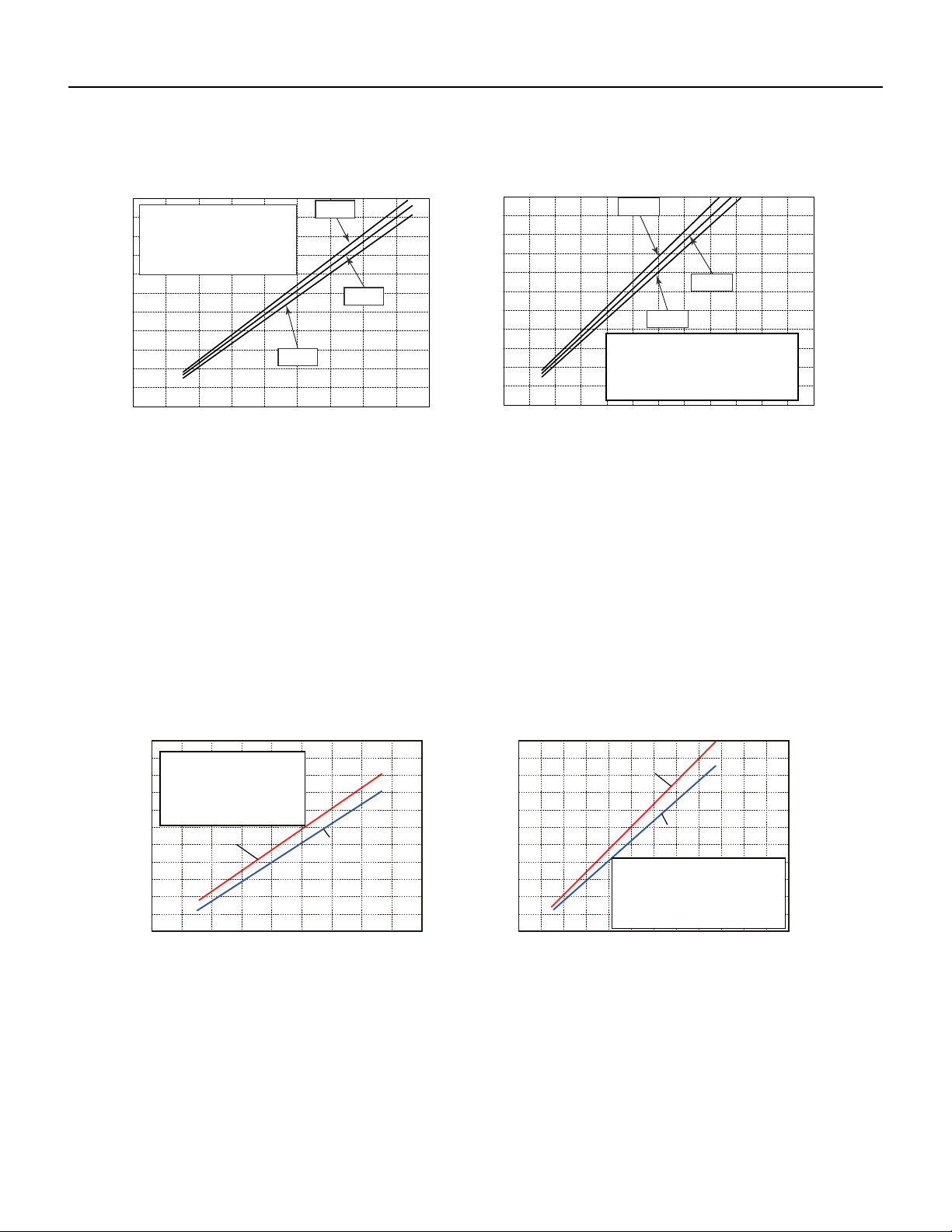
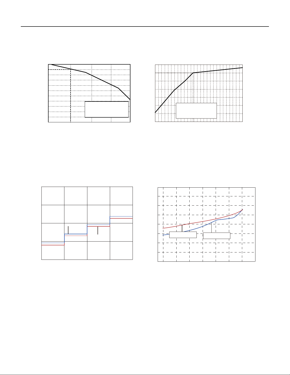
Figure 204
18-24kK Operation Characteristics curve
Figure 203
9-12K Operation Characteristics curve
110
90706050403020100
1201009080706050403020100
80
11
10
9
8
7
6
5
4
3
2
1
0
11
10
9
8
7
6
5
4
3
2
1
0
• Conditions
Indoor : DB80˚F/WB66.9˚F
High
Outdoor : DB95˚F
Indoor air flow :
220V
230V
240V
220V
230V
240V
Current (A)
Current (A)
Compressor frequency(Hz)
Compressor frequency(Hz)
Pipe lengt : 24.6ft
• Conditions
Pipe lengt : 24.6ft
Indoor : DB70˚F/WB60˚F
Outdoor : DB19.94˚F/WB19.04˚F
Indoor air flow : High
Cooling
Heating
Cooling Heating
0 01 02 30 0 4 0 5 0 6 07 09
80
11
10
9
8
7
6
5
4
3
100 20 30 40 50 60 70 80 90 100 110 120
2
1
0
Compressor speed (rps)
Current (A)
11
10
9
8
7
6
5
4
3
2
1
0
Compressor speed (rps)
Current (A)
24K
24K
18K
18K
Outdoor:DB95°F
Indoor air flow:Super High
Conditions
Indoor:DB80°F/WB66.9°F
Pipe length:24.6ft
Indoor air flow:Super High
Pipe length:24.6ft
Conditions
Indoor:DB70°F/WB60°F
Outdoor:DB19.94°F/WB19.04°F
19 PB
SPECIFICATIONS
Figure 205
36K Operation Characteristics curve
Cooling
Heating
24K
0
2
4
6
8
10
12
14
0 02 001
120
0
2
4
6
8
10
12
14
0 02 100 120
Conditio
n
Indoor:DB 80°F
WB66
°F
Indoor air flow: Super High
Pipe length:24 39/64ft
Condition
Indoor:DB 70°F
Indoor air flow: Super High
Pipe length:24 39/64ft
Current(A)
40 60 80
Compressor Frequency(Hz)
Current(A)
40 60 80
Compressor Frequency(Hz)
20 PB
SPECIFICATIONS
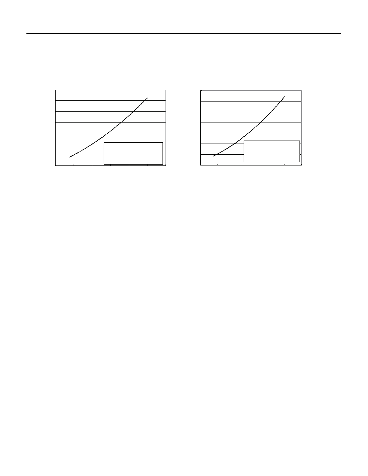
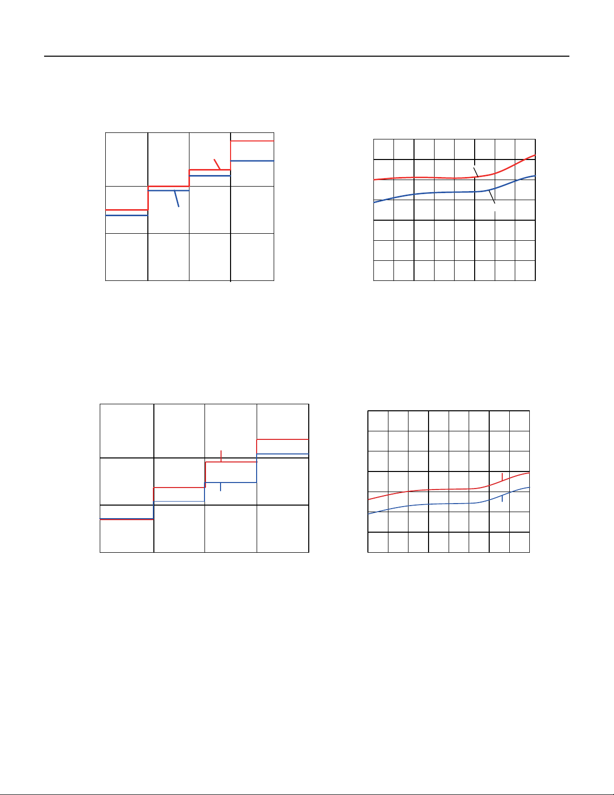
Figure 206
9-12K Capacity Variation Ratio According to Temperature
Figure 207
18-24 K Capacity Variation Ratio According to Temperature
Cooling Heating
5-4 41
110
100
90
80
70
60
50
40
23 32 41 50
Outdoor temp.(°F)
Capacity ratio (%)
100
105
95
90
85
80
75
70
65
89.6 91.4 93.2 95 96.8 98.6 100.4 102.2 104
105.8 107.6 109.4
60
55
50
Outdoor temp.(°F)
Capacity ratio (%)
Conditions
Outdoor:DB95°F
flow:Super HighIndoor air
Indoor:DB
80°F
/WB66.9
°F
Pipe length:
24.6ft
Conditions
Outdoor:DB19.94°F/WB19.04°F
Indoor:DB
70°F
air flow:SuperIndoor High
Pipe length:
24.6ft
Cooling
-4 5 41
110
100
90
80
70
60
50
40
23 32 41 50
Outdoor temp.(°F)
Capacity ratio (%)
100
105
95
90
85
80
75
70
65
60
55
50
Capacity ratio (%)
Outdoor:DB95°F
Indoor air flow:Super High
Conditions
Indoor:DB
80°F
/WB66.9
°F
89.6 91.4 93.2 95 96.8 98.6 100.4 102.2 104
105.8 107.6 109.4
Outdoor temp.(°F)
Pipe length:
24.6ft
Conditions
Indoor:DB
70°F
Outdoor:DB19.94°F/WB19.04°F
Indoor air flow:Super High
Pipe length:
24.6ft
Heating
21 PB
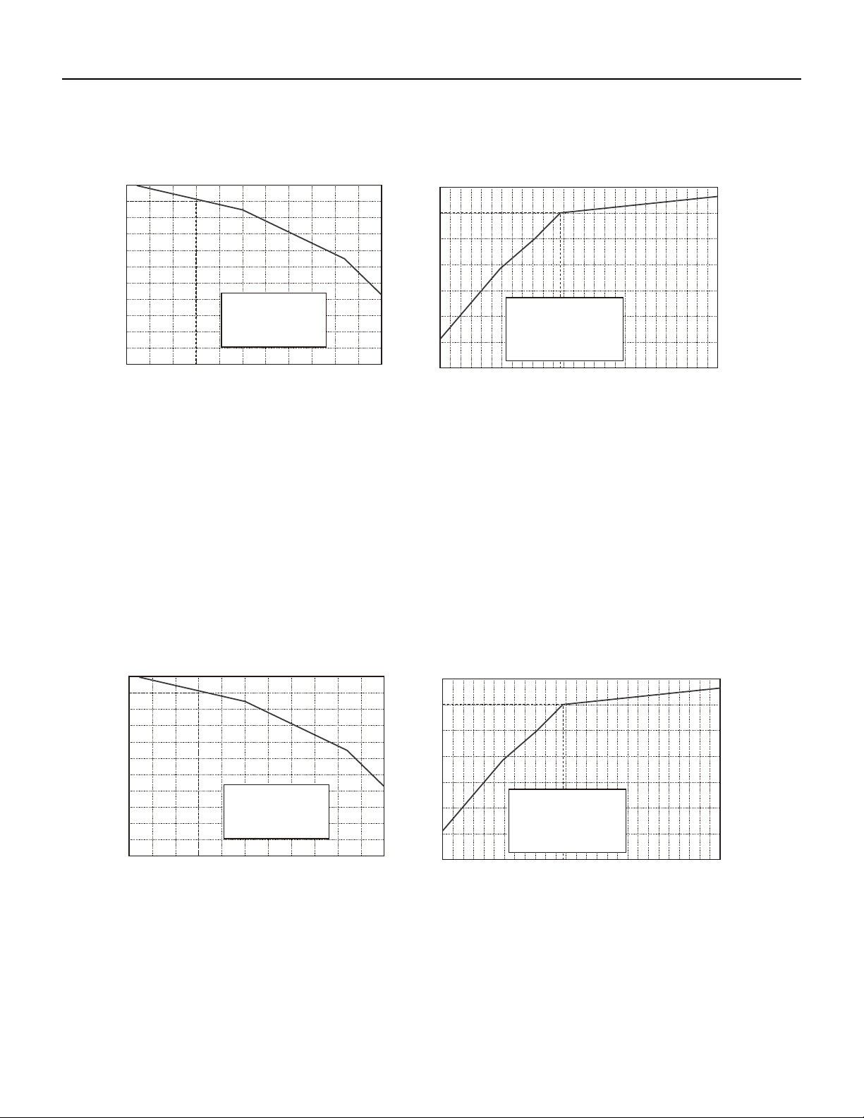
SPECIFICATIONS
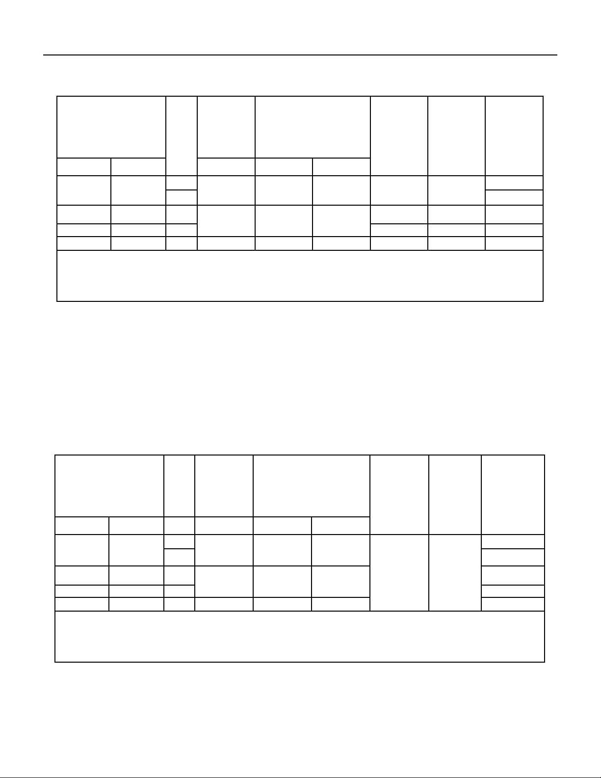
Figure 208
36K Capacity Variation Ratio According to Temperature
Figure 209
9-12K Noise Curve
Cooling Heating
90 95 100 105 110
100
105
95
90
85
80
75
70
65
60
55
50
Outdoor temp. (˚F) utdoor temp. (˚F)O
Capacity ratio (%)
Capacity ratio (%)
Conditions
-4 5 41
Indoor:
DB 80°F
WB66
°F
Indoor air flow: Super High
Pipe length :
24 39/64f
t
110
100
90
80
70
60
50
40
23 32 41 50
Conditions
HighIndoor air
length:Pipe
Indoor:DB
70°F
flow:Super
24 39/64f
t
Indoor side noise when blowing Outdoor side noise when blowing
Indoor fan motor rotating speed
Noise/dB(A)
40 50 60 70
Compressor frequency(Hz)
50
60
30
40
20
Super High
Low
Middle
High
40
42
44
46
48
50
52
54
56
20 30 80 90
Noise dB(A)
09&12K Cooling
09&12K Heating
09K
12K
22 PB
SPECIFICATIONS
Figure 210
18-24K Noise Curve
Figure 211
36K Noise Curve
20
30
40
50
L M H
18K
SH
24K
Indoor fan motor rating speed
Noise/dB(A)
46
48
50
52
54
56
58
60
20 30 40 50 60 70 80 90 100
Compressor frequency(Hz)
Noise dB(A)
Heating
Cooling
Indoor side noise Outdoor side noise
30
40
50
60
L
36K
30K
30K
HS
Noise/dB(A)
M
H
Indoor fan motor rating speed
45
50
55
60
65
70
75
80
20 30 40 50 60 70 80 90 100
Compressor frequency(Hz)
Noise dB(A)
Indoor side noise Outdoor side noise
36K
23 PB
Rated cooling connecting
indoor and (DB/WB)
Model Pressure of
gas pipe con‑
necting indoor
and outdoor
unit
Inlet and outlet pipe tempera‑
ture of heat exchanger
Fan speed of
indoor unit
Fan speed of
outdoor unit
Compresso r
frequency (Hz)
Indoor Outdoor PSI T1 (°F) T2 (°F)
80/67 95/75 9k 130.44~144.93 in:46.4~51.8
out:51.8~57.2
in:167~181.4
out:98.6~118.4
Super High High 52
12k 72
80/67 95/75 18k 130~142 in:46.4~51.8
out:51.8~57.2
in:167~181.4
out:98.6~118.4
Super High High 75
80/67 95/75 24k Super High High 87
80/66 95/75 36k 130~145 46.8 to 52.8 127 to 96.8 Super High High 60
T1: Inlet and outlet pipe temperature of evaporator
T2: Inlet and outlet pipe temperature of condenser
P: Pressure at the side of big valve
Connection pipe length: 24.6ft.
SPECIFICATIONS
Rated Heating connecting
indoor and (DB/WB)
Model Pressure
of gas pipe
connecting
indoor and
outdoor unit
Inlet and outlet pipe tempera-
ture of heat exchanger
Fan speed of
indoor unit
Fan speed
of outdoor
unit
Compresso r
frequency (Hz)
Indoor Outdoor PSI T1 (oF) T2 (oF)
70/60 19.94 /19.04 9k
362.32~405.80
in:167~181.4
out:98.6~113
in:33.8~37.4
out:35.6~42.8
Super High High 65
12k 77
70/60 47/43 18k
507~550
in:167~181.4
out:98.6~113
in:33.8~37.4
out:35.6~42.8
90
70/60 47/43 24k 87
70/- 20/19 36k 507~550 134.4 to 102 36 to 39 58
T1: Inlet and outlet pipe temperature of evaporator
T2: Inlet and outlet pipe temperature of condenser
P: Pressure at the side of big valve
Connection pipe length: 24.6ft.
Figure 212
Cooling Data Sheet in Rated Frequency
Figure 213
Heating Data Sheet in Rated Frequency
24 PB
SPECIFICATIONS
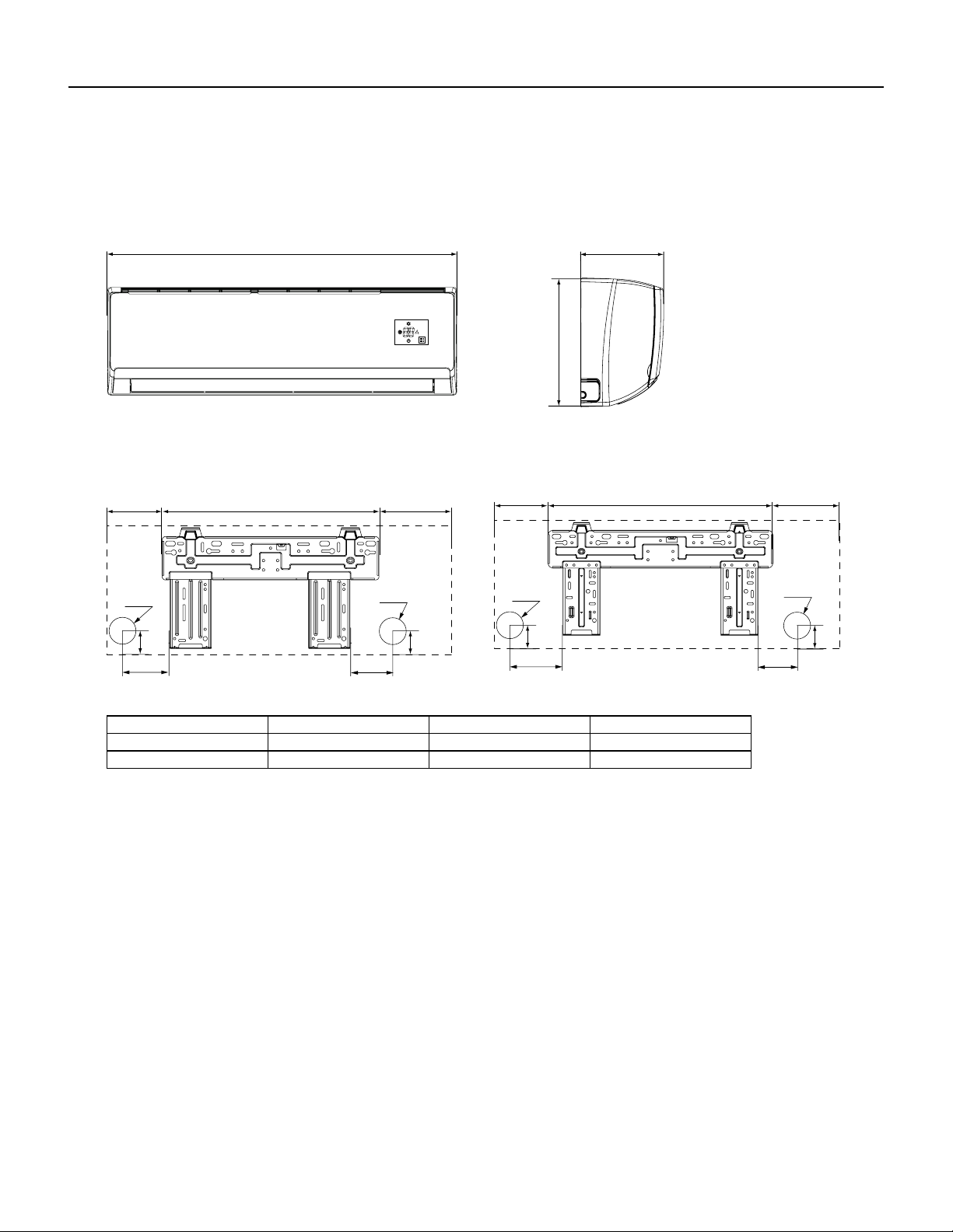
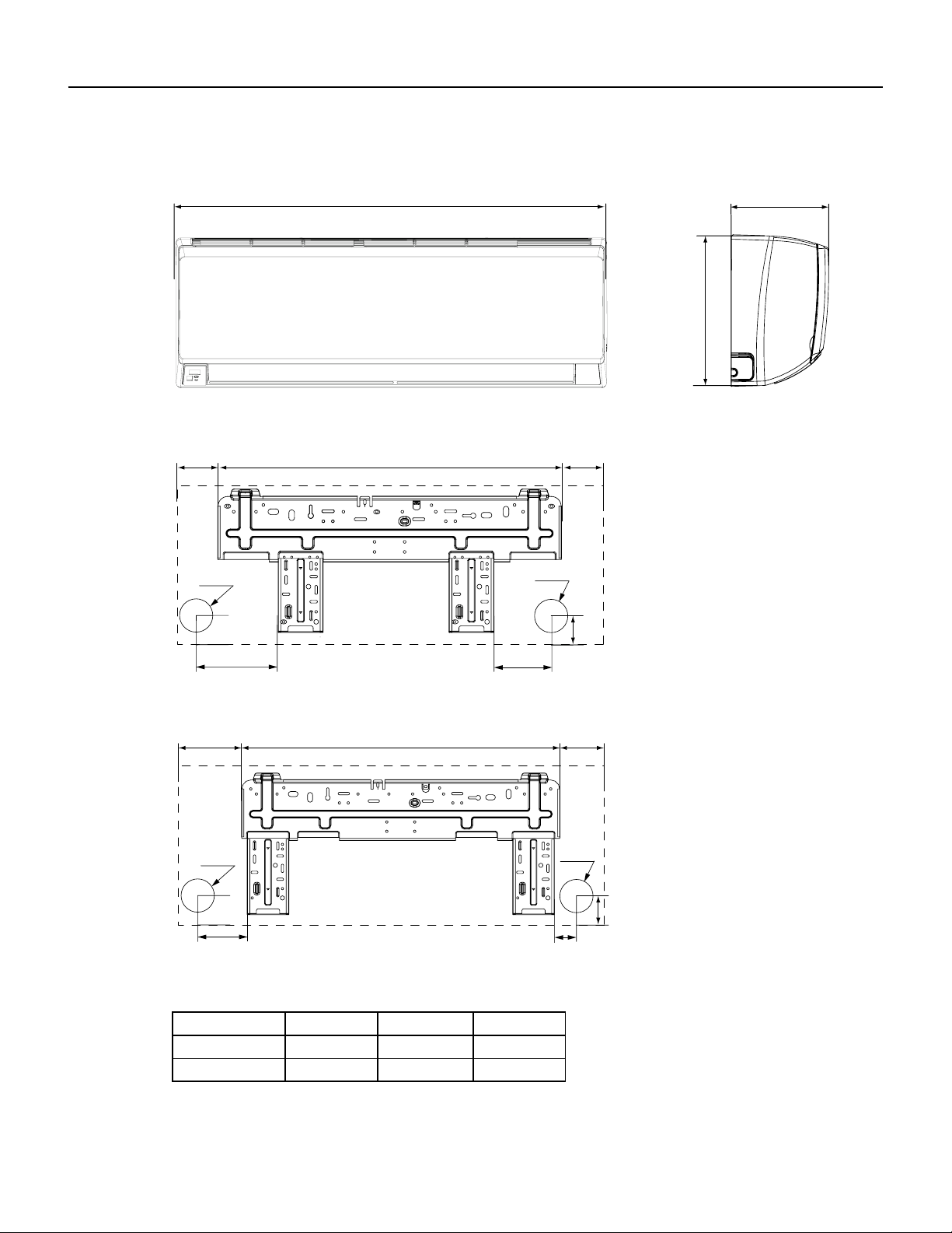
Figure 224
9-12K Indoor Unit Dimensions
W
D
H
Models W H D
09K 31 1/8 10 13/16 7 7/8
12K 33 1/4 11 3/8 8 1/4
12K
09K
3 9/16
5 7/8
1/8
2
6 5/8 18 1/4 6 1/4
2Φ
3/16
Φ2 3/16
2 1/8
1 5/1624 7/8 7 1/16
4 15/16
3 1/4
1 3/8
Φ2 3/16
2 3/16Φ
1 3/8
Unit: “ (inches)
25 PB
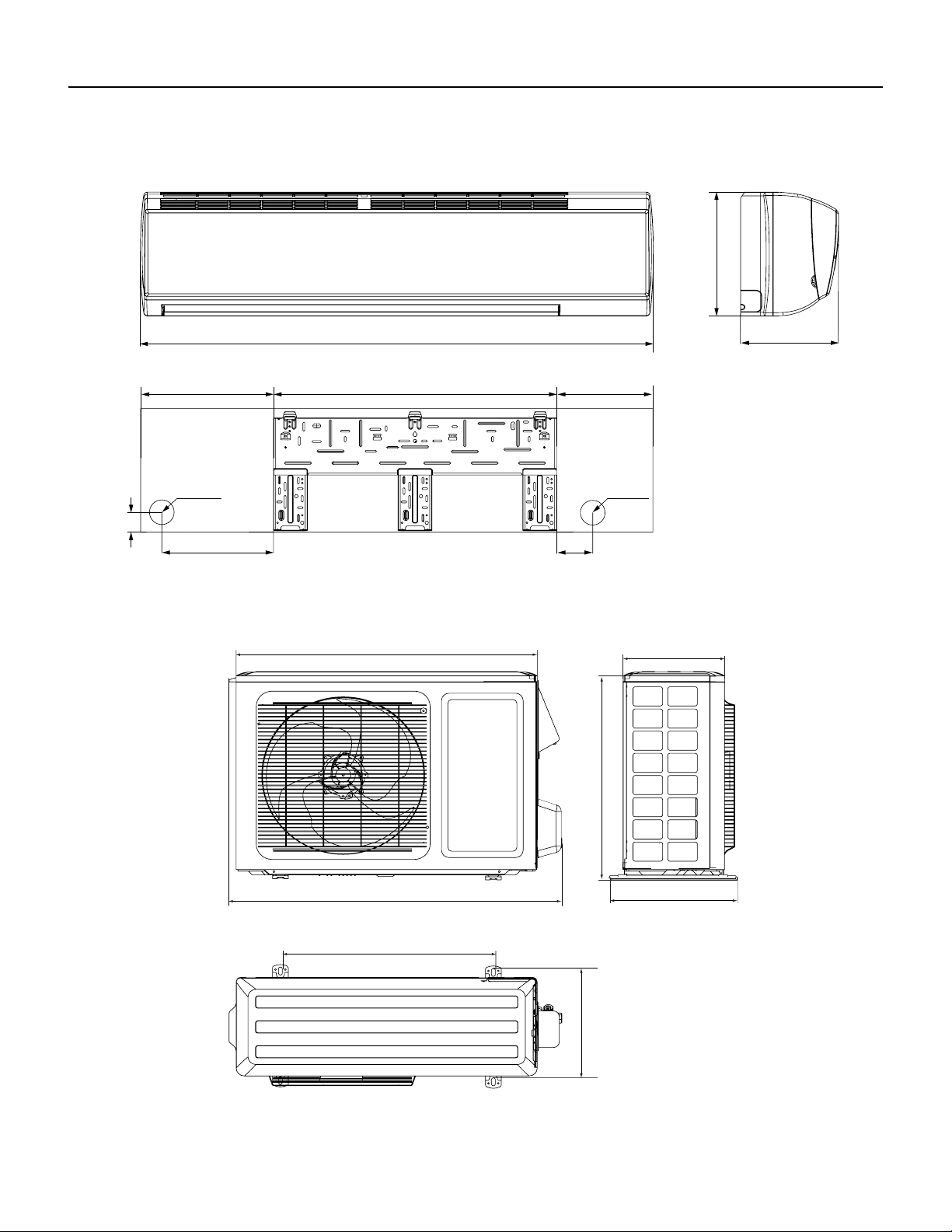
Figure 225
18-24K Indoor Unit Dimensions
SPECIFICATIONS
W
D
H
4 72 3/167
5 1/2
7 1/2
1 1/2
Φ2 3/16
Φ2 3/16
3 1/8
6
1 11/16
8 1/8 27 7 5/16
Φ2 3/4
Φ2 3/4
18K
24K
Models W H D
18K 38 3/16 11 13/16 8 13/16
24K 42 7/16 12 13/16 9 11/16
Unit: “ (inches)
26 PB
SPECIFICATIONS
Figure 227
9-12K Outdoor Unit Dimensions
Figure 226
36K indoor Unit Dimensions
53 9/64
12 53/64
10
11 19/32
3 1/2
1 37/64
13 25/32 1029 3/8
Φ2 3/4
Φ2 3/4
Unit: “ (inches)
21 1/4
11 1/4
30
10
12 5/8
33 3/8
21 1/4
Unit: “ (inches)
27 PB
SPECIFICATIONS
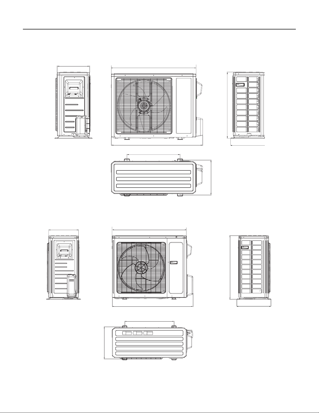
Figure 228
18-24K Outdoor Unit Dimensions
Figure 229
36K Outdoor Unit Dimensions
Unit: “ (inches)
35
13 3/8
27 9/16
15 5/8
38
14 5/16
22
14 37/64
31 7/64
16 13/16
15 9/16
39 1/2
24
36 7/32
Unit: “ (inches)
28 PB
OPERATION
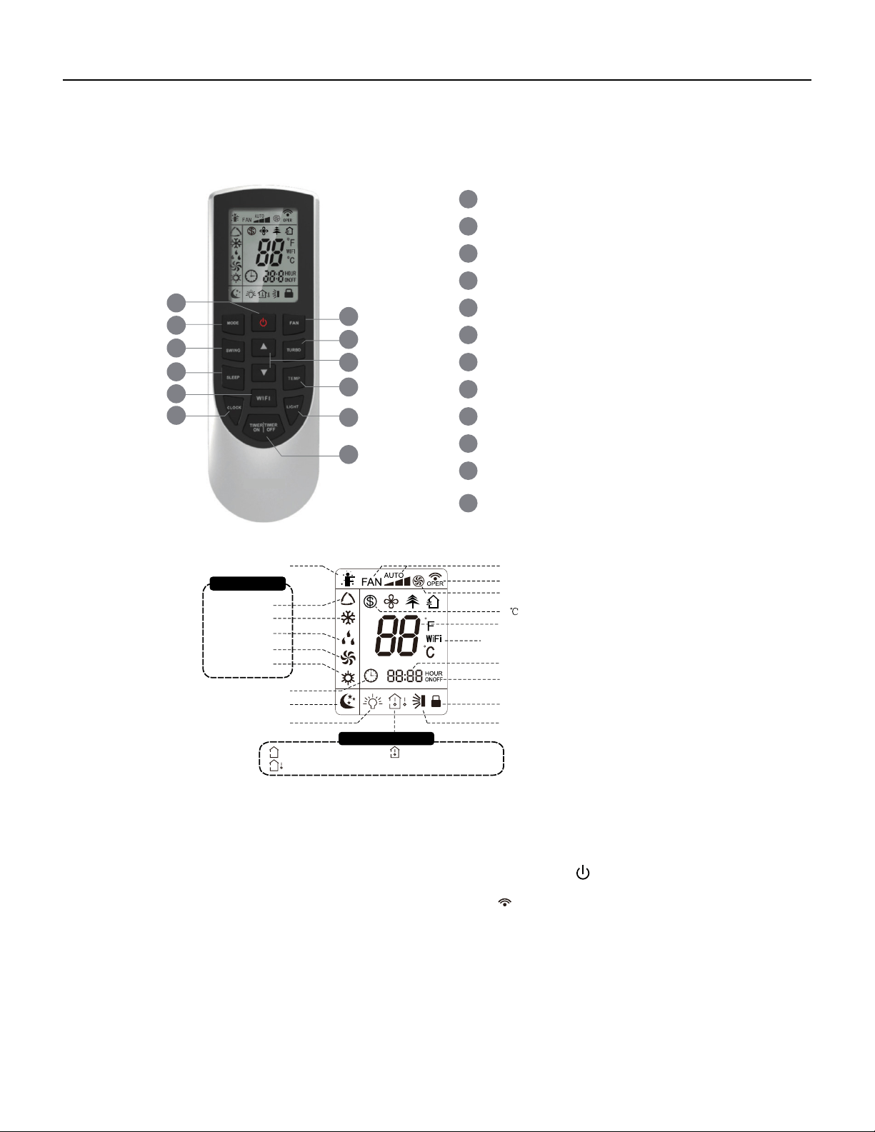
Figure 301
Remote Control Button Identification
69700657 / 69700623
Introduction for icons on display screen
5
3
6
8
10
12
11
9
7
4
2
1
1
2
3
4
5
6
7
8
9
10
11
12
ON/OFF button
MODE button
FAN button
SWING button
TURBO button
TEMP button
WiFi button
LIGHT button
CLOCK button
TIMER ON / TIMER OFF
button
SLEEP button
▲
▲
/ button
Set time
TIMER OFF
TIMER ON /
Child lock
Send signal
Turbo mode
8
heating function
Set temperature
Up & down swing
Set fan speed
Light
Temp. display type
:Set temp.
:Outdoor ambient temp.
bient temp.
Sleep mode
Clock
Temp. display type
:Indoor am
Heat mode
Fan mode
Dry mode
Cool mode
Auto mode
I feel
Operation mode
WiFi
This is a general remote controller.Some
models have this function while some
do not. Please refer to the actual models.
{
Introduction for buttons on remote controller
Note:
● This is a general use remote controller, it could be used for the air conditioners with multifunction; For some function, which the
model doesn't have, if press the corresponding button on the remote controller that the unit will keep the original running status.
● After putting through the power, the air conditioner will give out a sound. Operation indicator " " is ON (red indicator, the colour is
different for different models). After that, you can operate the air conditioner by using remote controller.
●
Under on status, pressing the button on the remote controller, the signal icon " "
on the display of remote controller will blink once
and the air conditioner will give out a “de” sound, which means the signal has been sent to the air conditioner.
● Under off status, set temperature and clock icon will be displayed on the display
of remote controller (If timer on, timer off and light functions are set, the corre- sponding icons will be displayed on the display of
remote controller at the same
time); Under on status, the display will show the corresponding set function icons.
29 PB
OPERATION
Remote Control Description
● When selecting auto mode, air conditioner will operate automatically according to ex-factory setting. Set temperature can't be adjusted and
will not be displayed as well. Press "FAN" button can adjust fan speed. Press "SWING" button can adjust fan blowing angle.
● After selecting cool mode, air conditioner will operate under cool mode. Cool indicator on indoor unit is ON. (This indicator is not available
for some models).Press "▲" or "
▲
" button to adjust set temperature. Press "FAN" button to adjust fan speed. Press "SWING" button to
adjust fan blowing angle.
" on indoor unit is ON.(This ● When selecting dry mode, the air conditioner operates at low speed under dry mode. Dry indicator "
indicator is not available for some models). Under dry mode, fan speed can't be adjusted. Press "SWING" button to adjust fan blowing
angle.
● When selecting fan mode, the air conditioner will only blow fan, no cooling and no heating. All indicators are OFF. Press "FAN" button to
adjust fan speed. Press "SWING" button to adjust fan blowing angle.
● When selecting heating mode, the air conditioner operates under heat mode. Heat indicator on indoor unit is ON. (This indicator is not
available for some models).Press "▲" or "
▲
" button to adjust set temperature. Press "FAN" button to adjust fan speed. Press "SWING"
button to adjust fan blowing angle. (Cooling only unit won't receive heating mode signal. If setting heat mode with remote controller, press
ON/OFF button can't start up the unit).
Note:
● For preventing cold air, after starting up heating mode, indoor unit will delay 1~5 minutes to blow air (actual delay time is depend on indoor
ambient temperature).
● Set temperature range from remote controller: 60.8 ~ 86°F; Fan speed: auto, low speed, medium speed, high speed.
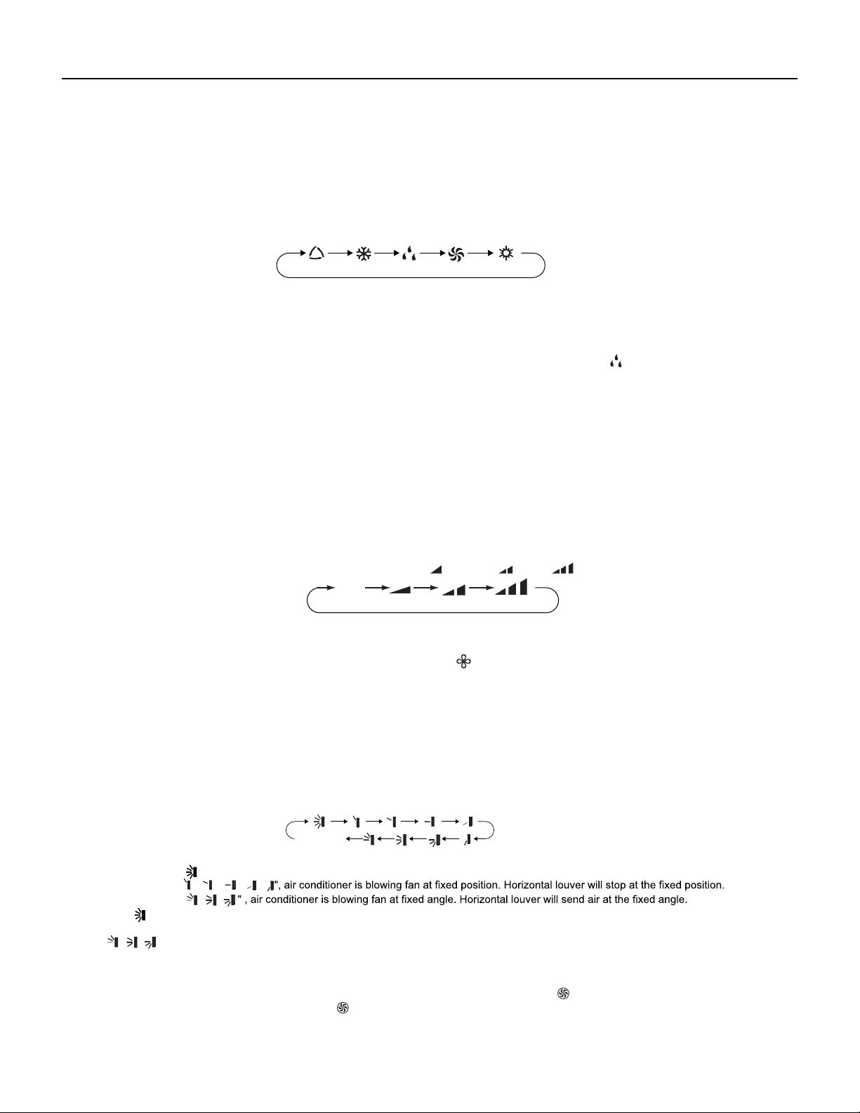
3. FAN button
Pressing this button can set fan speed circularly as: auto (AUTO), low(
) ,medium( ), high( ).
1. ON/OFF button
Press this button to turn on the unit. Press this button again to turn off the unit.
2. MODE button
Press this button to select your required operation mode.
FANAUTO COOL DRY HEAT
5. TURBO button
Under COOL or HEAT mode, press this button to turn to quick COOL or quick HEAT mode. " " icon is displayed on remote controller.
Press this button again to exit turbo function and " " icon will disappear.
Auto
4. SWING button
Press this button can select up&down swing angle. Fan blow angle can be selected circularly as below:
", air conditioner is blowing fan automatically. Horizontal louver will automatically swing up & down at maximum angle.
、 、 、 、
、
● When selecting "
● When selecting "
● When selecting "
、
"button above 2s to set your required swing angle. When reaching your required angle, release the button.● Hold "
Note:
● "
、 、
" may not be available. When air conditioner receives this signal, the air conditioner will blow fan automatically.
no display
(horizontal louvers stops at current position)
Note:
● Under AUTO speed, air conditioner will select proper fan speed automatically according to ex-factory setting.
● Fan speed under dry mode is low speed.
● X-FAN function:Hold fan speed button in COOL or DRY mode, the icon “ ” is displayed and the indoor fan will continue operation for a
few minutes in order to dry the indoor unit even though you have turned off the unit. After energization, X-FAN OFF is defaulted. X-FAN is not
available in AUTO, FAN or HEAT mode.
This function indicates that moisture on evaporator of indoor unit will be blowed after the unit is stopped to avoid mould.
●Having set X-FAN function on:After turning off the unit by pressing ON/OFF button indoor fan will continue running for a few minutes.at low
speed.In this period,Hold fan speed button to stop indoor fan directly.
●Having set X-FAN function off: After turning off the unit by pressing ON/OFF button, the complete unit will be off directly.
30 PB
OPERATION
Remote Control Description
6. ▲/
▲
button
12.
TIMER ON / TIMER OFF button
● Press "▲" or "
▲
" button once increase or decrease set temperature 1
°F
. Holding "▲" or "
▲
" button, 2s later, set temperature on remote
(Temperature can't be adjusted under auto mode)
● When setting TIMER ON,
▲
TIMER OFF or CLOCK, press "▲" or " " button to adjust time. (Refer to CLOCK, TIMER ON, TIMER OFF
buttons)
10. LIGHT button
Press this button to turn off display light on indoor unit. "
display light. " " icon is displayed.
11. CLOCK button
● This function is only available for some models.
" icon on remote controller disappears. Press this button again to turn on
9. WIFI button
Press " WiFi " button to turn on or turn off WiFi function. When WiFi function is turned on, the " WiFi " icon will be displayed on remote
controller; Under status of remote controller off, press "MODE" and " WiFi " buttons simultaneously for 1s,WiFi modulewill restore to factory
default setting.
● Clock time adopts 24-hour mode.
● The interval between two operation can't exceeds 5s. Otherwise, remote controller will quit setting status. Operation for TIMER ON/TIMER
OFF is the same.
Press this button to set clock time. " " icon on remote controller will blink. Press "▲" or "
▲
" button within 5s to set clock time. Each
pressing of "▲" or "
▲
" button, clock time will increase or decrease 1 minute. If hold "▲" or "
▲
" button, 2s later, time will change quickly.
" icon stops blinking.
Note:
● TIMER ON button
"TIMER ON" button can set the time for timer on. After pressing this button, "
" icon disappears and the word "ON" on remote controller
blinks. Press "▲" or "
▲
"button to adjust TIMER ON setting. After each pressing "▲" or "
▲
" button, TIMER ON setting will increase or
decrease 1min. Hold "▲" or "
▲
" button, 2s later, the time will change quickly until reaching your required time. Press "TIMER ON" to
" icon resumes displaying. Cancel TIMER ON: Under the condition that TIMER ON is
started up, press "TIMER ON" button to cancel it.
● TIMER OFF button
"TIMER OFF" button can set the time for timer off. After pressing this button,"
" icon disappears and the word "OFF" on remote
controller blinks. Press "▲" or "
▲
" button to adjust TIMER OFF setting. After each pressing "▲" or "
▲
" button,
TIMER OFF setting will increase or decrease 1min. Hold "▲" or "
▲
" button, 2s later, the time will change quickly until reaching your
required time. Press "TIMER OFF" word "OFF" will stop blinking. " " icon resumes displaying. Cancel TIMER OFF. Under the condition
that TIMER OFF is started up, press "TIMER OFF" button to cancel it.
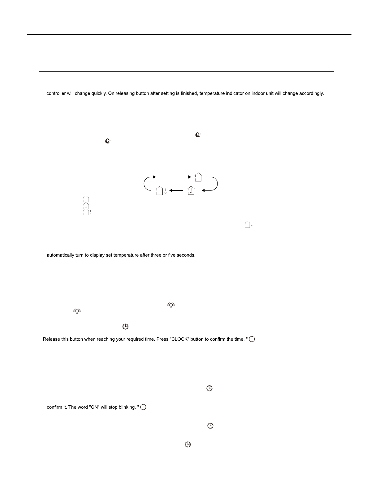
" or no display with remote controller, temperature indicator on indoor unit displays set temperature.
" with remote controller, temperature indicator on indoor unit displays indoor ambient temperature.
" with remote controller, temperature indicator on indoor unit displays outdoor ambient temperature.
● When selecting "
● When selecting "
● When selecting "
Note:
"signal, while it displays indoor set
7. SLEEP button
Under COOL, HEAT mode, press this button to start up sleep function. " " icon is displayed on remote controller. Press this button again
to cancel sleep function and " " icon will disappear.
8.
TEMP button
By pressing this button, you can see indoor set temperature, indoor ambient temperature or outdoor ambient temperature on indoor units
display. The setting on remote controlleris selected circularly as below:
●
Outdoor temperature display is not available for some models. At that time, indoor
unit receives "
temperature.
● Only for the models whose indoor unit has dual-8 display.
● It's defaulted to display set temperature when turning on the unit.There is no display in the remote controller.
● When selecting displaying of indoor or outdoor ambient temperature, indoor temperature indicator displays corresponding temperature and
no display

31 PB
OPERATION
Remote Control Description
Note:
● Under on and off status, you can set TIMER OFF or TIMER ON simultaneously.
● Before setting TIMER ON or TIMER OFF, please adjust the clock time.
● After starting up TIMER ON or TIMER OFF, set the constant circulating valid. After that, air conditioner will be turned on or turned off
according to setting time. ON/OFF button has no effect on setting. If you Don't need this function, please use remote controller to cancel it.
4. Temperature display switchover function
Under OFF status, press "
▲
" and "MODE" buttons simultaneously to switch temperature display between
℃
and
℉
.
5. I FEEL Function
● Under energy-saving function, fan speed is defaulted at auto speed and it can't be adjusted.
●
Under energy-saving function, set temperature can't be adjusted. Press "TURBO"
button and the remote controller won't send signal.
● Sleep function and energy-saving function can't operate at the same time. If energy-saving function has been set under cooling mode,
press sleep button will cancel energy-saving function. If sleep function has been set under cooling mode, start up the energy-saving
function will cancel sleep function.
Function introduction for combination buttons
1. Energy-saving function
Under cooling mode, press "TEMP" and " CLOCK" buttons simultaneously to start up or turn off energy-saving function. When energy-saving
function is started up, "SE" will be shown on remote controller, and air conditioner will adjust the set temperature automatically according to
ex-factory setting to reach to the best energy-saving effect. Press "TEMP" and "CLOCK"buttons simultaneously again to exit energy-saving
function.
Note:
2. 46ºF
heating function
Under heating mode, press "TEMP" and "CLOCK" buttons simultaneously to start
up or turn off
46ºF
heating function. When this function is
started up, " " and "
46ºF”
will be shown on remote controller, and the air conditioner keep the heating status
at 46ºF
. Press "TEMP" and
"CLOCK" buttons simultaneously again to exit 46ºF
heating function.
Note:
● Under 46ºF
heating function, fan speed is defaulted at auto speed and it can't be adjusted.
● Under 46ºF
heating function, set temperature can't be adjusted. Press
"
TURBO
"
button and the remote controller won't send signal.
● Sleep function and 46ºF
heating function can't operate at the same time. If 46ºFheating function has been set under cooling mode, press
sleep button will cancel 46ºF heating function. If sleep function has been set under cooling mode, start up the 46ºF
heating function will
cancel sleep function.
● Under
℉
temperature display, the remote controller will display 46
℉
heating.
3. Child lock function
Press "▲" and "
▲
" simultaneously to turn on or turn off child lock function. When child lock function is on, " " icon is displayed on remote
controller. If you operate the remote controller, the " " icon will blink three times without sending signal to the unit.
Press "▲" and "MODE" buttons simultaneously to start I FEEL function and " " will be displayed on the remote controller. After this function
is set, the remote controller will send the detected ambient temperature to the controller and the unitwill automatically adjust the indoor
temperature according to the detected tempera-ture. Press this two buttons simultaneously again to close I FEEL function and " " will
disappear.
● Please put the remote controller near user when this function is set. Do not put the remote controller near the object of high temperature
or low temperature in order to avoid detecting inaccurate ambient temperature.When I FEEL function is turned on, the remote controller
should be put within the area where indoor unit can receive the signal sent by the remote controller.
If “H1” is displayed on the remote controller while it’s not operated by the professional person/after-sales person, it belongs to the
misoperation.
Please operate it as below to cancel it.Under the OFF status of remote controller, hold the Mode button for 5s to cancel “H1” display
.
Note:
● If remote controller displays “H1”, it belongs to the normal function reminder. If the unit is defrosting under heating mode, it operates
according to H1 defrosting mode. “H1” won’t be displayed on the panel of indoor unit;
● Once you set H1 mode, if you turn off unit by remote controller, H1 will display 3 times on the remote controller and then disappear;
● Also, when you set H1 mode, when you change to heating mode, H1 will display 3 times on the remote controller and then disappear.
32 PB
OPERATION
Remote Control Description
Operation guide
Replacement of batteries in remote controller
● During operation, point the remote control signal sender at the receiving window on indoor unit.
1. After putting through the power, press "ON/OFF" button on remote controller to turn on the air conditioner.
2. Press "MODE" button to select your required mode: AUTO, COOL, DRY, FAN, HEAT.
3. Press "▲" or "
▲
" button to set your required temperature. (Temperature can't be adjusted under auto mode).
4. Press "FAN" button to set your required fan speed: auto, low, medium and high speed.
5. Press "SWING" button to select fan blowing angle.
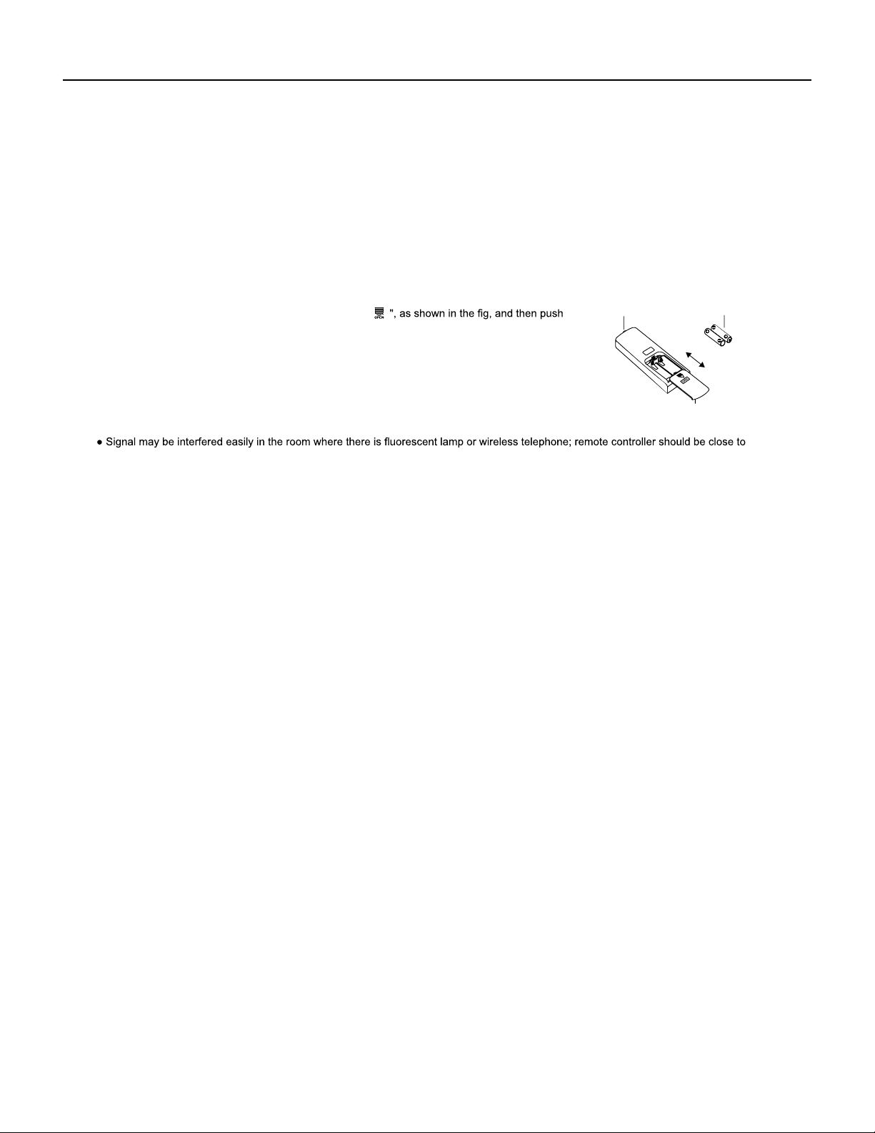
1. Press the back side of remote controller marked with "
● The distance between signal sender and receiving window should be no more than 8m, and there should be no obstacles between them.
indoor unit during operation.
● Replace new batteries of the same model when replacement is required.
● If you won't use remote controller for a long time, please take out the batteries.
● If the display on remote controller is fuzzy or there's no display, please replace batteries.
out
the cover of battery box along the arrow direction.
signal sender battery
2. Replace two AAA 1.5V dry batteries, and make sure the position of "+" polar and "-" polar
are correct.
3. Reinstall the cover of battery box.
Note:
Cover of battery box
remove
reinstall

33 PB
OPERATION
9-24k Sequence of Operation
1.Basic function of system
(1)Cooling mode
(2)Drying mode
(1) Under this mode, fan and swing operates at setting status. Temperature setting range is 60.8~86.0
O
F.
(2) During malfunction of outdoor unit or the unit is stopped because of protection, indoor unit keeps original operation status.
(3)Heating mode
(1) Under this mode, fan operates at low speed and swing operates at setting status. Temperature setting range is 60.8~86.0
O
F.
(2) If the outdoor unit malfunctions, or the unit is stopped because of protection, indoor unit keeps original operation status.
(3) Protection status is same as that under cooling mode.
(4) Sleep function is not available for drying mode.
(1) Under this mode, Temperature setting range is 60.8~86.0
O
F.
(2) Working condition and process for heating mode:
When unit heating mode is turned on, the indoor unit enters into cold air prevention status. When the unit is stopped or at OFF status,
and indoor unit has been initially started, the unit enters into residual heat-blowing status.
a. During cooling operation, protection function is same as that under cooling mode.
b. During heating operation, protection function is same as that under heating mode.
(4)Working method for AUTO mode:
1.Working condition and process for AUTO mode:
a.Under AUTO mode, standard heating Tpreset=68.0
O
F and standard cooling Tpreset=77.0
O
F. The unit will switch mode automatically
according to ambient temperature.
2.Protection function
3. Display: Set temperature is the set value under each condition. Ambient temperature is (Tamb.-Tcompensation) for heat pump unit
and Tamb. for cooling only unit.
4. If there's I feel function, T compensation is 0. Others are same as above.
(5)Fan mode
Under this mode, indoor fan operates at set fan speed. Compressor, outdoor fan, 4-way valve and electric heating tube stop operation.
Indoor fan can select to operate at high, medium, low or auto fan speed. Temperature setting range is 60.8~86.0
O
F.
2. Other control
(1) Buzzer
Upon energization or command from the unit or remote controller , the buzzer will give out a beep.
(2) Auto button
If press this auto button when turning off the unit, the complete unit will operate at auto mode. Indoor fan operates at auto fan speed
and swing function is turned on. Press this auto button at ON status to turn off the unit.
(3) Auto fan
Heating mode: During auto heating mode or normal heating ode, auto fan speed will adjust the fan speed automatically according to
ambient temperature and set temperature.
(4) Sleep
After setting sleep function for a period of time, system will adjust set temperature automatically.
(5) Timer function:
General timer and clock timer functions are compatible by equipping remote controller with different functions.
(6) Memory function
Memorized compensation temperature, off-peak energization value.
Memory content: mode, up&down swing, light, set temperature, set fan speed, general timer (clock timer can't be memorized).
After power recovery, the unit will be turned on automatically according to memory content.
(7) Health function
Turn on the unit by pressing auto button, and the health is defaulted ON.
34 PB
OPERATION
9-24k Sequence of Operation
(8)I feel control mode
After controller received I feel control signal and ambient temperature sent by remote controller, controller will work according to the ambient
temperature sent by remote controller.
(9)Compulsory defrosting function
(10)Refrigerant recovery function:
(1) Start up compulsory defrosting function
Under ON status, set heating mode with remote controller and adjust the temperature to 60.8
O
F. Press “+, -, +, -, +,-” button successively
within 5s and the complete unit will enter into compulsory defrosting status. Meanwhile, heating indicator on indoor unit will ON 10s and OFF
0.5s successively. (Note: If complete unit malfunctions or stops operation due to protection, compulsory defrosting function can be started
up after malfunction or protection is resumed.
(2) Exit compulsory defrosting mode
After compulsory defrosting is started up, the complete unit will exit defrosting operation according to the actual defrosting result, and the
complete unit will resume normal heating operation.
(11)Ambient temperature display control mode
(1) Enter refrigerant recycling function
Within 5min after energizing (unit ON or OFF status ), continuously press LIGHT button for 3 times within 3s to enter refrigerant
recycling mode; Fo is displayed and refrigerant recycling function is started. At this moment, the maintenance people closes liquid valve.
After 5min, stick the thimble of maintenance valve with a tool. If there is no refrigerant spraying out, close the gas valve immediately and
then turn off the unit to remove the connection pipe.
(2) Exit refrigerant recycling function
After entering refrigerant recycling mode, when receive any remote control signal or enter refrigerant recycling mode for
25min, the unit will
exit refrigerant recycling mode automatically If the unit is in standby mode before refrigerant recycling, it will be still in standby mode after
1. When user set the remote controller to display set temperature (corresponding remote control code: 01), current set temperature will be
displayed.
2. Only when remote control signal is switched to indoor ambient temperature display status (corresponding remote control code: 10) from
other display status (corresponding remote control code: 00, 01,11),controller will display indoor ambient temperature for 3s and then turn
back to display set temperature.
Under this mode, indoor fan operates at set fan speed. Compressor, outdoor fan, 4-way valve and electric heating tube stop operation.
Indoor fan can select to operate at high, medium, low or auto fan speed. Temperature setting range is 60.8~86.0
O
F.
(12)Off-peak energization function:
Adjust compressors minimum stop time. The original minimum stop time is 180s and then we change to:
The time interval between two start-ups of compressor can't be less than 180+T s(0≤T≤15). T is the variable of controller. Thats to say
the minimum stop time of compressor is 180s~195s.
(13) X-fan mode
When X-fan function is turned on, after turn off the unit, indoor fan will still operate at low speed for 2min and then the complete unit will be
turned off. When x-fan function is turned off, after turn off the unit, the complete unit will be turned off directly.
(14) 46º heating function
Under heating mode, you can set 46º heating function by remote controller. The system will operate at 46ºset temperature.
(15) Turbo fan control function
Set turbo function under cooling or heating mode to enter into turbo fan speed. Press fan speed button to cancel turbo wind.
No turbo function under auto, dry or fan mode.
35 PB
OPERATION
9-24k Sequence of Operation
Outdoor Units
1. Input Parameter Compensation and Calibration
(1) Check the ambient temperature compensation function Indoor ambient temperature compensation function.
a. In cooling mode, the indoor ambient temperature participating in computing control = (T
indoor ambient temperature
–
⊿
T
cooling indoor ambient temperature
compensation
)
b. In heating mode, the indoor ambient temperature participating in computing control= (T
indoor ambient temperature
–
⊿
T
heating indoor ambient temperature
compensation
)
(2) Check effective judgment controls of parameters
temperature thermo-bulb is judged not to be connected into place, the mainboard of outer units will display failure of the outdoor exhaust
temperature thermo-bulb (not connected into place), stop the machine for repairing, and resume the machine by remote controls of ON/
OFF.
2. Basic Functions
(1) Cooling Mode
1. Conditions and processes of cooling operation:
a. Judgment of exhaust detection temperature change:
After the compressor starts up and runs for 10 minutes, if the compressor frequency f ≥ 40Hz, and the rising value Texhaust (T
exhaust (after start-
up for 10 minutes)
- T
exhaust (before start-up)
) <35.6ºF , the outdoor exhaust temperature thermo-bulb can be judged not to be connected into place (judging
b. Comparative judgment of exhaust detection temperature and condenser detection temperature (T
pipe temperature
= T
outdoor pipe temperature in cooling
mode
, T
pipe temperature
= T
indoor pipe temperature in heating mode
): After the compressor starts up and runs for 10 minutes, if the compressor frequency f ≥
40Hz, and T
pipe temperature
≥(T
exhaust+37.4
), the outdoor exhaust temperature thermobulb can be judged not to be connected into place (judging
2. Temperature setting range
(2) Dehumidifying Mode
1. Conditions and processes of dehumidifying operations: Same as the cooling mode;
2. The temperature setting range is: 61~86ºF;
(3) Air-supplying Mode
(1) If T
outdoor ambient temperature
≥ [T
low-temperature cooling temperature
], the temperature can be set at: 61~86ºF (Cooling at room temperature);
(2) If T
outdoor ambient temperature
< [T
low-temperature cooling temperature
], the temperature can be set at: 77~86ºF (Cooling at low temperature), that is, the
minimum setting temperature for outer units judgment is 77ºF .
1. The compressor, outdoor fans and four-way valves are switched off;
2. The temperature setting range is: 61~86ºF.
(1) If the compressor is shut down, and [T
setup
– (T
indoor ambient temperature
–
⊿
T
cooling indoor ambient temperature compensation)
] ≤ 32.9ºF , start up the
machine for cooling, the cooling operation will start;
(2) During operations of cooling, if 32ºF ≤ [T
setup
– (T
indoor ambient temperature
–
⊿
T
cooling indoor ambient temperature compensation)
] < 35.6ºF , the cooling
operation will be still running;
(3) During operations of cooling, if 35.6ºF ≤ [Tsetup – (T
indoor ambient temperature
–
⊿
T
cooling indoor ambient temperature compensation)
], the cooling operation
will stop after reaching the temperature point.
(4) Heating Mode
1. Conditions and processes of heating operations: (T indoor ambient temperature is the actual detection temperature of indoor environment
thermo-bulb, Theating indoor ambient temperature compensation is the indoor ambient temperature compensation during heating
operations)
2. The temperature setting range in this mode is: 61~86ºF .
(1) If the compressor is shut down, and [(T
indoor ambient temperature
–
⊿
T
heating indoor ambient temperature compensation
) –T
setup
] ≤ 32.9ºF , start the machine
to enter into heating operations for heating;
(2) During operations of heating, if 32ºF ≤ [(T
indoor ambient temperature
–
⊿
T
heating indoor ambient temperature compensation
) –T
setup
] < 35.6ºF , the heating
operation will be still running;
(3) During operations of heating, if 35.6ºF ≤ [(T
indoor ambient temperature
–
⊿
T
heating indoor ambient temperature compensation
) –T
setup
], the heating operation
will stop after reaching the temperature point.
36 PB
OPERATION
9-24k Sequence of Operation
3. Special Functions
Defrosting Control
①
Conditions for starting defrosting
the defrosting operation will start.
②
③
T
outdoor pipe temperature
≥ (T
outdoor ambient temperature
– [T ];
④
The continuous running time of defrosting reaches [tmax. defrosting time].
(1) Start the machine to enter into heating operation for heating, the compressor is switched on.
(2) Defrosting:
1. Cooling mode
Start the machine to enter into cooling operation for cooling, the compressor is switched on.
2. Dehumidifying mode
Same as the cooling mode.
3. Air-supplying mode
The compressor is switched off.
4. Heating mode
a. Defrosting starts: the compressor is shut down, and restarts it after 55-second delay.
b. Defrosting ends: the compressor stops, then starts it after 55-second delay.
2. The status of 4-way valve control under the heating mode: getting power;
(1) 4-way valve power control under heating mode
a. Starts the machine under heating mode, the 4-way valve will get power immediately.
(2) 4-way valve power turn-off control under heating mode
(2) Outer Fans Control
Notes:
After remote shutdown, safety stops, and when the machine stops after reaching the temperature point, as well as after the compressor
.
(3) 4-way valve control
(3) Defrosting control under heating mode:
4. Control Logic
(1) Compressor Control
Start the compressor after starting cooling, heating, dehumidifying operations, and the outer fans start for 5s; When the machine is
shutdown, in safety stops and when switching to air-supplying mode, the compressor will stop immediately. In all modes: once the
compressor starts up, it will not be allowed to stop until having run for the [tmin. compressor running time] (Note: including cases of
shutdown when the temperature point is reached; except the cases requiring stopping the compressor such as fault protection, remote
shutdown, mode switching etc.); In all modes: once the compressor stops, it will be allowed be restart after 3-minute delay (Note: The
indoor units have a function of power memory, the machine can be restarted after remote shutdown and powering up again without
delay).
a. Defrosting begins: The power of 4-way valve will be cut after 50s of entering into the defrosting compressor.
b. Defrosting stops: The 4-way valve will get power after 50s of exiting the defrosting compressor.
a. When you should turn off the power or switch to other mode under heating mode, the power of 4-way valve will be cut
after 2 minutes
of the compressor stopped.
b. When all kinds of protection stops, the power of 4-way valve will be cut after delaying 4 minutes.
(4) Evaporator frozen-preventing protection function
At the mode of Cooling, dehumidifying:
Evaporator frozen-preventing protection function is allowed to begin after 6 min of starting the compressor.

37 PB
OPERATION
9-24k Sequence of Operation
(5) Overload protection function
Overload protection function at the mode of Cooling and dehumidifying
1. Starting estimation:
After the compressor stopped working for 180s, if T
inner pipe
> [T
frozen-preventing frequency-limited temperature
(the temperature of hysteresis is 35.6ºF )],
the machine is only allowed to start for operating, otherwise it should not be started, and should be stopped to treat according to the frozen-
preventing protection: Clear the trouble under the mode of power turn-off / heating, and the protection times are not counted.
2. Frequency limited
[T
frozen-preventing normal speed frequency-reducing temperature
] ≤[T
inner pipe T frozen-preventing frequency-limited temperature
] , you should limit the frequency raising of
compressor.
3. Reducing frequency at normal speed:
If [T
frozen-preventing high speed frequency-reducing temperature
] ≤[T
inner pipe T frozen-preventing normal speed frequency-reducing temperature
], you should adjust the compressor
frequency by reducing 8Hz/90s till the lower limit;
4. Reducing frequency at high speed:
If [T
frozen-preventing power turn-off temperature
] ≤T
inner pipe
[T
frozen-preventing high speed frequency-reducing temperature
] you should adjust the compressor frequency by
reducing 30Hz/90s till the lower limit;
5. Power turn-off:
If the T
inner pipe
<[T
frozen-preventing power turn-off temperature
], then frozen-preventing protect to stop the machine; If T[
frozen-preventing frequency-limited temperature
]
<T
inner pipe
, and the compressor has stopped working for 3 minutes, the whole machine should be allowed to operate.
6. If the frozen-preventing protection power turn-off continuously occurs for six times, it should not be resumed automatically, and you should
press the ON/OFF button to resume if the fault keeps on. During the process of running, if the running time of compressor exceeds the t
evaporator frozen-preventing protection times zero clearing time , the times of frozen-preventing power turn-off should be cleared to recount.
The mode of stopping the machine or transferring to supply air will clear the trouble times immediately (if the trouble can not be resumed,
mode transferring will not clear it).
Overload protection function at the mode of heating
Starting estimation :
After the compressor stopped working for 180s, if T inner pipe T heating overload frequency-limited temperature (the temperature of
hysteresis is 35.6ºF ), the machine is allowed to start, otherwise it should not be started, and should be stopped to treat according to the
overload protection:
Clear the trouble at the mode of power turn-off / heating, and the protection times are not counted.
1. Starting estimation:
After the compressor stopped working for 180s, if T
outer pipe
<[T
Cooling overload frequency-limited temperature
] (the temperature of hysteresis is 35.6ºF ), the
machine is allowed to start, otherwise it should not be started, and should be stopped to treat according to the overload protection: Clear the
trouble at the mode of power turn-off / heating, and the protection times are not counted.
2. Frequency limited
If [T
Cooling overload frequency-limited temperature
] ≤[T
outer pipe T Cooling overload frequency reducing temperature at normal speed
], you should limit the frequency raising of
compressor.
3. Reducing frequency at normal speed and power turn-off:
If [T
Cooling overload frequency reducing temperature at high speed
] ≤T
outer pipe
< [T
Cooling overload power turn-off temperature
] , you should adjust the compressor frequency
by reducing 8Hz/90s till the lower limit; After it was running 90s at the lower limit, if [T
Cooling overload frequency reducing temperature at normal speed
]≤T
outer pipe
,
then Cooling overload protects machine stopping;
4. Reducing frequency at high speed and stop machine:
If [T
Cooling overload frequency reducing temperature at high speed
]≤T
outer pipe
[T
Cooling overload power turn-off temperature
], you should adjust the compressor frequency by
reducing 30Hz/90s till the lower limit; After it was running 90s at the lower limit, if [T
Cooling overload frequency reducing temperature at normal speed
] ≤[T
outer pipe]
,
then Cooling overload protects machine stopping;
5. Power turn-off:
If the [T
Cooling overload power turn-off temperature
] ≤T
outer pipe
, then Cooling overload protects machine stopping; If [T
outer pipe
]<[T
Cooling overload frequency-limited
temperature
]and the compressor has been stopped working for 3 minutes, the machine should be allowed to operate.
6. If the Cooling overload protection power turn-off continuously occurs for six times, it should not be resumed automatically, and you should
press the ON/OFF button to resume if the fault keeps on. During the process of running, if the running time of compressor exceeds the t
overload protection times zero clearing time , the times of overload protection power turn-off should be cleared to recount. The mode of
stopping the machine or transferring to supply air will clear the trouble times immediately (if the trouble can not be resumed, transferring
mode will not clear it).

38 PB
OPERATION
9-24k Sequence of Operation
1. Frequency limited
If [T
heating overload frequency-limited temperature
]≤T
inner pipe
<[T
heating overload frequency reducing temperature at normal speed
] , you should limit the frequency raising of
compressor.
2. Reducing frequency at normal speed and stopping machine:
If T[
heating overload frequency reducing temperature at normal speed
]≤T
inner pipe
<[T
heating overload frequency reducing temperature at high speed
], you should adjust the compressor
frequency by reducing 8Hz/90s till the lower limit; After it was running 90s at the lower limit, if T heating overload frequency reducing
temperature at normal speed ≤T inner pipe, then overload protects machine stopping;
3. Reducing frequency at high speed and power turn-off:
If [T
heating overload frequency reducing temperature at high speed
]≤T
inner pipe
<[T
heating overload power turn-off temperature
], you should adjust the compressor frequency by
reducing 30Hz/90s till the lower limit; After it was running 90s at the lower limit, if T heating overload frequency reducing temperature at normal
speed ≤T outer pipe, then Cooling overload protects machine stopping;
4. Power turn-off:
If the [T
heating overload power turn-off temperature
] ≤T
inner pipe
, then overload protects machine stopping; If T inner pipe T heating overload frequency-limited
temperature and the compressor has been stopped working for 3 minutes, the machine should be allowed to operate.
5. If the overload protection power turn-off continuously occurs for six times, it should not be resumed automatically, and you should press
the ON/OFF button to resume if the fault keeps on. During the process of running, if the running time of compressor exceeds the t overload
protection times zero clearing time , the times of overload protection power turn-off should be cleared to recount. The mode of stopping the
machine or transferring to supply air will clear the trouble times immediately (if the trouble can not be resumed, transferring mode will not clear
it). Protective function for discharge temperature of compressor
1. Starting estimation:
After the compressor stopped working for 180s, if T
Discharge
<T
Discharge limited temperature
(the temperature of hysteresis is 35.6ºF ), the machine is
allowed to start, otherwise it should not be started, and should be stopped to treat according to the discharge temperature:
The machine should be stopped or transferred to supply air, the trouble should be cleared immediately, and the protection times are not
counted.
2. Frequency limited
If [T
Limited frequency temperature during discharging
] ≤T
Discharge
<[T
frequency reducing temperature at normal speed during discharging
] , you should limit the frequency raising of
compressor.
3. Reducing frequency at normal speed and stopping machine:
If [T
frequency reducing temperature at normal speed during discharging
] ≤T
Discharge
<[T
frequency reducing temperature at high speed during discharging
], you should adjust the compressor
frequency by reducing 8Hz/90s till the lower limit; After it was running 90s at the lower limit, if [T
frequency reducing temperature at normal speed during discharging
]
≤T
Discharge
, you should discharge to protect machine stopping;
4. Reducing frequency at high speed and power turn-off:
If [T
frequency reducing temperature at high speed during discharging
] ≤T
Discharge
<[T
Stop temperature during discharging
], you should adjust
the compressor frequency by reducing 30Hz/90s till the lower limit; After it was running 90s at the lower limit, if [T
frequency reducing temperature at normal
speed during discharging
] ≤T
Discharge
, you should discharge to protect machine stopping;
5. Power turn-off:
If the [T
Power turn-off temperature during discharging
] ≤T
Discharge
, you should discharge to protect machine stopping; If [T
Discharge
]<[T
Limited frequency temperature during
discharging
] and the compressor has been stopped for 3 minutes, the machine should be allowed to operate.
6. If the discharging temperature protection of compressor continuously occurs for six times, it should not be resumed automatically, and you
should press the ON/OFF button to resume. During the process of running, if the running time of compressor exceeds the t Protection times
clearing of discharge , the discharge protection is cleared to recount. Stopped or transferred to supply air mode will clear the trouble times
immediately (if the trouble can not be resumed, mode transferring also will not clear it).
7. Frequency limited
If [I
Limited frequency when overcurrent
] ≤I
AC Electric current
<[I
frequency reducing when overcurrent
], you should limit the frequency raising of compressor.
8. Reducing frequency:
If [I
Frequency reducing when overcurrent
] ≤[I
AC Electric current I Power turn-off when overcurrent
] , you should reduce the compressor frequency till the lower limit or exit
the frequency reducing condition;
9. Power turn-off:
If [I
Power turn-off machine when overcurrent
] ≤[I
AC Electric current
] , you should carry out the overcurrent stopping protection; If I
AC Electric current
<[T
Limited frequency when
overcurrent
] and the compressor has been stopped for 3 minutes, the machine should be allowed to operate.
10. If the overcurrent protection continuously occurs for six times, it should not be resumed automatically, and you should press the ON/OFF
button to resume. During the process of running, if the running time of compressor exceeds the [t
Protection times clearing of over current
] , the discharge
protection is cleared to recount.

39 PB
OPERATION
9-24k Sequence of Operation
(6)Voltage sag protection
After start the compressor, if the time of DC link Voltage sag [U
Sagging protection voltage
] is measured to be less than t Voltage sag protection time ,
the machine should be stop at once, hand on the voltage sag trouble, reboot automatically after 30 minutes.
(7)Communication fault
When you have not received any correct signal from the inner machine in three minutes, the machine will stop for communication fault. When
you have not received any correct signal from driver IC (aim to the controller for the separating of main control IC and driver IC), and the
machine will stop for communication fault. If the communication is resumed, the machine will be allowed to operate.
(8)Module protection
Testing the module protective signal immediately after started, once the module protective signal is measured, stop the machine with module
protection immediately. If the module protection is resumed, the machine will be allowed to operate. If the module protection continuously
occurs for three times, it should not be resumed automatically, and you should press the ON/OFF button to resume. If the running time of
compressor exceeds the [t
Protection times clearing of module
] , the module protection is cleared to recount.
(9)Module overheating protection
(10)Compressor overloads protection
If you measure the compressor overload switch action in 3s, the compressor should be stopped for overloading. The machine should be
allowed to operate after overload protection was measured to resume. If the overloading protection continuously occurs for three times, it
should not be resumed automatically, and you should press the ON/OFF button to resume. The protection times of compressor is allowed to
clear after the compressor run [t
Protection times clearing of compressor overloading
] 30 minutes.
(11)Phase current overcurrent protection of compressor
During the running process of compressor, you could measure the phase current of the compressor, and control it according to the following
steps:
1. Starting estimation:
After the compressor stopped working for 180s, if T
Module
<[T
Module frequency limited temperature
](the temperature of hysteresis is 35.6ºF ), the machine
is allowed to start, otherwise it should not be started, and should be stopped to treat according to the module overheating protection: The
machine should be stopped or transferred to supply air, the trouble should be cleared immediately, and the protection times are not counted.
2. Frequency limited
If [T
Limited frequency temperature of module
] ≤T
Module
<[T
frequency reducing temperature at normal speed of module
] , you should limit the frequency raising of compressor.
3. Reducing frequency at normal speed and power turn-off:
If [T
frequency reducing temperature at normal speed of module
] ≤T
Module
<[T
frequency reducing temperature at high speed of module
], you should adjust the compressor frequency by
reducing 8Hz/90s till the lower limit; After it was running 90s at the lower limit, if [T
frequency reducing temperature at normal speed of module
] ≤T
Module
, you should
stop the machine for module overheating protection;
4. Reducing frequency at high speed and power turn-off:
If [T
frequency reducing temperature at high speed of module
]≤T
Module
<[T
Power turn-off temperature of module
] you should adjust the compressor frequency by reducing 30Hz/90s
till the lower limit; After it was running 90s at the lower limit, if [T
frequency reducing temperature at normal speed of module
] ≤T
Module
, you should stop the machine for
module overheating protection;
5. Power turn-off:
If the [T
Power turn-off temperature of module
] ≤T
Module
, you should stop the machine for module overheating protection; If T
Module
<[T
Limited frequency temperature of module
]
and the compressor has been stopped for 3 minutes, the machine should be allowed to operate.
6. If protection continuously occurs for six times, it should not be resumed automatically, and you should press the ON/OFF button to resume.
During the process of running, if the running time of compressor exceeds the [t
Protection times clearing of module
] , the discharge protection is cleared
to recount. Stopped or transferred to supply air mode will clear the trouble times immediately (if the trouble can not be resumed, mode
transferring also will not clear it).
1. Frequency limited
If [I
Limited frequency phase current
] ≤[I
Phase current T frequency reducing phase current
] , you should limit the frequency raising of compressor.
2. Reducing Frequency
If [I
Frequency Reducing Phase Current
]≤I
Phase Current
<[I
Power Turn-Off Phase Current
], the compressor shall continue to reduce frequency till the lowest frequency limit or
out of the condition of reducing frequency;
3. Power turn-off
If [I
Phase Current
]≥[I
Power Turn-Off Phase Current
], the compressor phase current shall stop working for overcurrent protection; if [I
Phase Current
]≤[I
Frequency Reducing Phase
Current
], and the compressor have stopped working for 3 min, the machine shall be allowed to operate;
4. If the overcurrent protection of compressor phase current continuously occurs for six times, it should not be resumed automatically, and
you should press the ON/OFF button to resume. During the process of running, if the running time of compressor exceeds the [t
Clearing Time of
Compressor Phase Current Times
] , the overcurrent protection is cleared to recount.
40 PB
OPERATION
9-24k Sequence of Operation
(12) Starting-up Failure Protection for Compressor
Stop the compressor after staring fails, then restart it after 20s if the fault doesn't show.If starting fails 3 consecutive
times, it shall be reported as Starting-up Failure, and then restart up it after 3 min. When it still not be able to operate through carry out the
above process for 5 times, it is available if you press ON/OFF. The compressor should be cleared after it runs 2 min.
(13) Out-of-Step Protection for Compressor
the out-of-step protection shall be stopped; if it can run for lasting power turn-off 3 min, the machine shall be allowed to operate. If it still can't
run automatically when the out-of-step protection for compressor happens to stop working for 6 times in succession, it needs to press ON/OFF
to operate. And if the running time is more than 10 min, the power turn-off times for out-of-step protection shall be cleared and recounted.
(14) Voltage Abnormity Protection for DC Bus
To detect voltage abnormity protection for dc bus after completing the pre-charge:
1.Over-High Voltage Protection for DC Bus:
If it found the DCbus voltage U
DC
>[U
DC Jiekuangchun Protection
], turn off PFC and stop the compressor at once, and it shall show the DC over-high
voltage failure; it should clear out the failure when the voltage dropped to U
DC
<[U
DC Jiekuangchun Recovery
] and the compressor stopped for 3 min.
2.Over-Low Voltage Protection for DC Bus:
If it found the DC bus voltage U
DC
<[U
DC Wantuochun Protection
], turn off PFC and stop the compressor at once, and it shall show the DC over-low
voltage; and it should clear out the failure when the voltage raised to U
DC
>[U
DC Wantuochun Recovery
] and the compressor stopped for 3 min.
3.To detect voltage abnormity protect for DC bus when getting electricity:
If it found the DC bus voltage U
DC
>[U
DC-Over-High Voltage
], turn off the relay at once, and shows voltage abnormity failure for DC Bus. And the failure
can't recover except to break off and get the electricity.
(17) Failure Detection for Sensor
(a) The compressor only detect the sensor failure after it start up 3 min in normal mode;
(b) It should detect the exhaust sensor failure immediately in the testing mode.
1. After start up the PFC, it should detect the protection signal of PFC immediately; under the condition of PFC protection, it should turn off the
PFC and compressor at the same time;
2. It shows the failure is cleared out if PFC Protection stopped working 3 min and recovers to run automatically;
3. If the PFC protection failure occurs 3 times consecutively, it will be available if you
press ON/OFF; and clear the PFC Protection
times when start up PFC for 10min.
4. Module Temperature Sensor:
(15)Abnormity Protection for Four-way Valve
Under the model of heating operation in good condition: the compressor is detected [T
Inner Tube
<(T
Inner Ring
-T
Abnormity Temperature Difference For Four-Way Valve
Reversion
)], during the running, it should be regarded as four-way valve reversion abnormity. And then it can run if stop the reversion abnormity
protection for four-way valve 3 min; and if it still can't run when the reversion abnormity protection for four-way valve happens to stop working
for 3 times in succession, it is available if presses ON/OFF.
Attention: the protection shall be shielded during the testing mode and defrosting process, and it shall be cleared out the failure and its times
immediately when turning off or delivering wind / cooling / dehumidifying mode conversed (the inverted mode Don't clear out the failure when it
can't recover to operate).
(16) PFC Protection
1. Outdoor Ambient Sensor: detect the failure of sensor at all times.
2. Outdoor Tube Sensor: You should not detect the failure of outdoor tube sensor within 10 minutes heating operation compressor except the
defrosting, and you could detect it at other time.
3. Outdoor Exhaust Sensor:
5. Disposal for Sensor Protection
(a) Short-Circuit Detection: the compressor should be detected immediately when the module temperature sensor occurs short-circuits;
(b) Open-Circuit Detection: the compressor should be detected on open-circuit when it runs 3min (it neednt 30s avoiding the module over-
heated).
(c) Detect the sensor failure at all times in the testing mode.
according to the over-high sensor, the machine should carry out the corresponding protection to stop working, and show the corresponding
temperature shutdown protection and sensor failure at the same time (for example: the compressor stops immediately when the outdoor tube
sensor short-circuit, and the machine shall show the overload protection and outdoor tube sensor failure).
(2) When the open-circuit of sensor is detected within 30s, The protection shall be stopped and it shall show the corresponding sensor failure.

41 PB
OPERATION
9-24k Sequence of Operation
6. Electric Heating Function of Chassis
7. Electric Heating Function of Compressor
(1) When T
outdoor amb.
≤32ºF , the electric heating of chassis will operate;
(2) When T
outdoor amb.
>35.6ºF , the electric heating of chassis will stop operation;
(3)When 32ºF <T
outdoor amb.
≤35.6ºF, the electric heating of chassis will keep original status.
(1) When T
outdoor amb.
≤23ºF , compressor stops operation, while the electric heating of compressor starts operation;
(2) When T
outdoor amb.
>28.4ºF , the electric heating of compressor stops operation;
(3) When 23ºF <T
outdoor amb.
≤28.4ºF , the electric heating of compressor will keep original status.
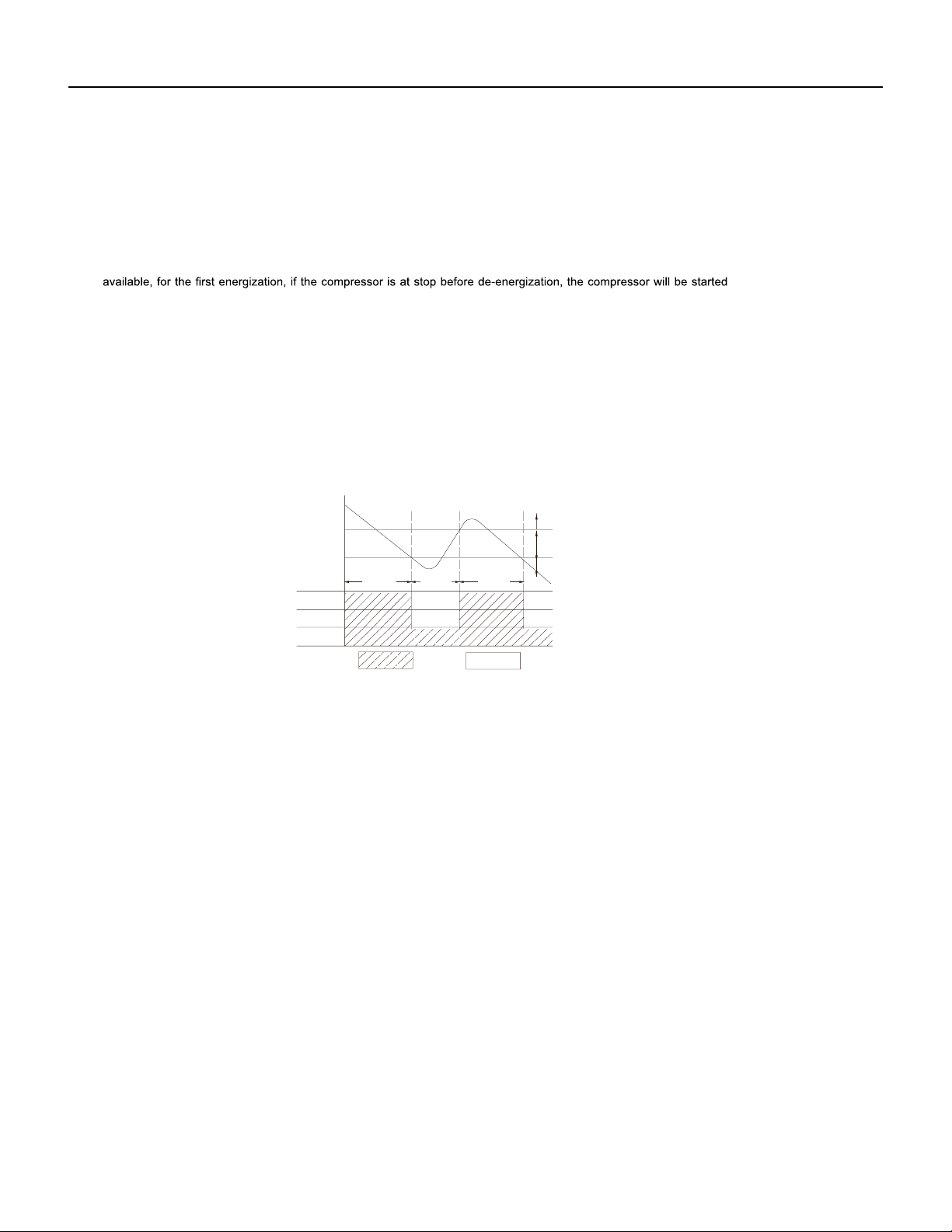
42 PB
OPERATION
36k Sequence of Operation
1. Temperature Parameters
Indoor preset temperature (Tpreset)
Indoor ambient temperature (Tamb.)
2. Basic Functions
Once energized, in no case should the compressor be restarted within less than 3 minutes. In the situation that memory functionis
lag; if the compressor is in operation before de-energization, the compressor will be started with a 3-minute lag; and once started, the
compressor will not be stopped within 6 minutes regardless of changes in room temperature;
(1) Cooling Mode
①
Working conditions and process of cooling
When Tamb. ≥ Tpreset, the unit will enter cooling operation, in which case the indoor fan, the outdoor fan and the compressor will work and
the indoor fan will run at preset speed.
When Tamb. ≤ Tpreset -3.6°F, the compressor will stop, the outdoor fan will stop with a time lag of 60s, and the indoor fan will run at preset
speed.
When Tpreset-3.6°F < Tamb.< Tpreset+1.8°F, the unit will remain at its previous state.
Under this mode, the four-way valve will be de-energized and temperature can be set within a range from 61°F~86°F. If the compressor is
shut down for some reason, the indoor fan and the swing device will operate at original state.
②
Protection
Run Stop
Antifreeze protection
Under cooling and dehumidifying mode, 6 minutes after the compressor is started:
If Tevap ≤ 35.6°F, the compressor will operate at reduced frequency.
If Tevap ≤ 30.2°F is detected for durative 3 minutes, the compressor will stop, and after 60 seconds, the outdoor fan will stop;and under
cooling mode, the indoor fan and the swing motor will remain at the original state.
If Tevap. ≥ 42.8°F and the compressor has remained at OFF for at least 3 minutes, the compressor will resume its original operation state.
Total current up and frequency down protection
If I
total
≤ 16A, frequency rise will be allowed; if I
total
≥ 17A, frequency rise will not be allowed; if I
total
≥ 18A, the compressor will run at reduced
frequency; and if I
total
≥ 20A, the compressor will stop and the outdoor fan will stop with a time lag of 60s.
(2) Dehumidifying Mode
①
Working conditions and process of dehumidifying.
If Tamb. > Tpreset+1.8°F, the unit will enter cooling and dehumidifying mode, in which case the compressor and the outdoor fan wil
l
operate and the indoor fan will run at low speed.
If Tpreset -3.6°F ≤ Tamb. ≤ Tpreset+1.8°F, the compressor remains at its original operation state.
If Tamb.< Tpreset-3.6°F , the compressor will stop, the outdoor fan will stop with a time lag of 60s, and the indoor fan will
operate at low speed.
②
Protection
Protection is the same as that under the cooling mode.
60-second blow at low speed.
If Tpreset+3.6°F < Tamb. < Tpreset+9°F, the unit will maintain its original operating status.
(3) Heating Mode
①
Working conditions and process of heating
If Tamb. ≤ Tpreset+3.6°F, the unit enters heating mode, in which case the four-way valve, the compressor and the outdoor fan will operate
simultaneously, and the indoor fan will run at preset speed in the condition of preset cold air prevention.
If Tamb. ≥ Tpreset+9°F, the compressor will stop, the outdoor fan will stop with a time lag of 60s, and the indoor fan will stop after
Under this mode, the four-way valve is energized and temperature can be set within a range of 61°F~86°F. The operating symbol, the
heating symbol and preset temperature are revealed on the display.
②
Condition and process of defrost
Tpreset
Tpreset +3˚F
Compressor
Outdoor fan
Indoor fan
Tamb.
Stop cooling
Start cooling
Original working state
≥ 6 min. ≥ 3 min. ≥ 6 min.
Set fan speed
without a 3 minute

43 PB
OPERATION
36k Sequence of Operation
When duration of successive heating operation is more than 45 minutes, or accumulated heating time more than 90 minutes, and one of the
following conditions is reached, the unit will enter the defrost mode after 3 minutes.
a. T outdoor amb. ≥ 41°F, T outdoor pipe ≤ 28.4°F; b. 28.4°F ≤ T outdoor amb.
c. 23.4°F < T outdoor amb. ≤ 28.4°F, T outdoor pipe ≤ 17.6°F;
d. 14°F < T outdoor amb. < 23°F, T outdoor pipe- T compensation ≤ T outdoor amb.-5.4°F;
e. T outdoor amb. < 14°F, T outdoor pipe- T compensation ≤ T outdoor amb.-5.4°F;
After energization, when defrosting for the first time T compensation=0°F. If it is not the firstl time for defrosting, the T compensation is
determined by the Toutdoor pipe of last time quitting defrosting.
a. Toutdoor pipe > 35.6°F, Tcompensation=0°F; b. Toutdoor pipe ≤ 35.6°F, Tcompensation=5.4°F.
At that time, the indoor fan stops and the compressor stops, and after 60 seconds the outer fan will stop, and then after 30 seconds, the four-
way valve will stop. After 30 seconds, the compressor is initiated for raising the frequency to defrost frequency.
When the compressor has operated under defrost mode for 10 minutes, or Touter tube ≥ 50°F, the compressor will be converted to 46Hz
operation.After 30 seconds, the compressor will stop. And after another 30 seconds, the four-way valve will be opened, and after 60 seconds,
the compressor and the outer fan will be started, the indoor fan will run under preset cold air prevention conditions,and H1 will be displayed
at temperature display area on the display panel. Defrost frequency is 70 Hz.
3.Protection
Cold air prevention
The unit is started under heating mode (the compressor is ON):
(4) Fan Mode
Under the mode, the indoor fan will run at preset speed
and the compressor, the outdoor fan, the four-way valve and the electric heater will
stop.
Under the mode, temperature can be set within a range of 61°F~86°F.
(5) AUTO Mode
①
Working conditions and process of AUTO mode
Under AUTO mode, standard cooling temperature Tpreset is 77°F and standard heating temperature Tpreset is 68°F.
①
In the case of Tindoor amb. < 75°F: if T tube ≤ 104°F and the indoor fan is at stop state, the indoor fan will begin to run at low speed with a
time lag of 2 minutes. Within 2 minutes, if T tube > 104°F, the indoor fan also will run at low speed; and after 1 minute operation atlow speed,
the indoor fan will be converted to operation at preset speed. Within 1 minute low speed operation or 2 minute non-operation, if T tube >
108°F, the fan will run at present speed.
②
In the case of Tindoor amb. < 75°F: if Ttube ≤ 108°F, the indoor fan will run at low speed, and after one minute, the indoor fan will
be converted to preset speed. Within 1 minute low speed operation, if Ttube > 104 ° F , the indoor fan will be converted to preset speed. Note:
Tindoor amb. indicated in
①
and
②
refers to, under initially heating mode, the indoor ambient temperature before the command to start the
compressor is performed according to the program, or after the unit is withdrawn from defrost, the indoor ambient temperature before the
defrost symbol is cleared.
Total current up and frequency down protection
If the total current I
total
≤ 16A, frequency rise will be allowed; if I
total
≥ 17A,frequency rise will not be allowed; if Itota l≥ 18A, the compressor will run
at reduced frequency; and if I
total ≥ 20A, the compressor will stop and the outdoor fan will stop with a time lag of 60s.
②
Protection
a. In cooling operation, protection is the same as that under the cooling mode;
b. In heating operation, protection is the same as that under the heating mode;
c. When ambient temperature changes, operation mode will be converted preferentially. Once started, the compressor will remain unchanged
for at least 6 minutes.
b. If Ttube ≥ 131°F, frequency rise is not allowed.
(6) Common Protection Functions and Fault Display under COOL, HEAT, DRY and AUTO Modes
①
Overload protection
Ttube:measured temperature of outdoor heat exchanger under cooling mode; and measured temperature of indoor heat ex-changer under
heating mode.
1) Cooling overload.
a. If Ttube ≤ 126°F, the unit will return to its original operation state.
a. Once energized, if Tamb. ≤ 71.6°F, the unit will be started under heating mode; if 71.6°F < Tamb.< 78.8°F, the unit will run under fanmode
and the run indicator will be bright; and if Tamb. ≥
78.8°F, the unit will be started under cooling mode.
b.Under AUTO mode,if Tamb. ≥ Tpreset +1.8ºF is detected,the unit will select to run under cooling mode,in which case implicit
preset temperature is 77 °F; if Tamb. ≤ Tpreset-1.8°F, the compressor will stop, the outdoor fan will stop with a time lag of 1 minute,
and the indoor fan will run at preset speed; and if Tpreset-1.8 °F < Tamb. < Tpreset+1.8ºF, the unit will remain at its original state.
c.Under AUTO mode, if Tamb. ≤ Tpreset+3.6°F is detected, the unit will select to run under heating mode, in which case implicit preset
temperature is 64°F;
if Tamb. ≥ Tpreset+9°F, the compressor will stop, the outdoor fan will stop with a time lag of 1 minute,and the indoor
fan will run under the mode of residue heat blowing; and if Tpreset+3.6°F < Tamb.< Tpreset+41°F, the unit will remainatits original state. The
cooling-only unit will run under fan mode.
d.Under AUTO mode, if 71.6°F < Tamb.< 78.8°F, the unit will remain at its original state.
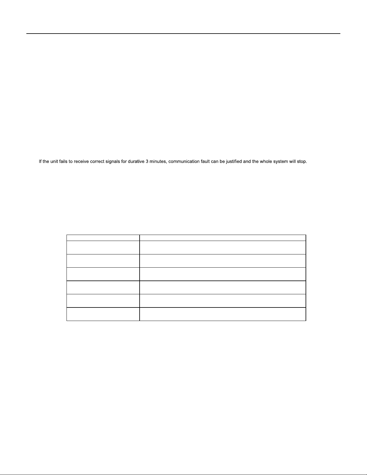
44 PB
OPERATION
36k Sequence of Operation
2) Heating overload
c. If Ttube ≥ 136°F, the compressor will run at reduced frequency.
d. If Ttube ≥ 144°F, the compressor will stop and the indoor fan will run at preset speed.
a. If Ttube ≤ 126°F, the unit will return to its original operation state.
b. If Ttube ≥ 131°F, frequency rise is not allowed.
c. If Ttube ≥ 136°F, the compressor will run at reduced frequency.
d. If Ttube ≥ 144°F,the compressor will stop and the indoor fan will blow residue heat and then stop.
Designation of sensors Faults
Indoor ambient temperature
The sensor is detected to be open-circuited or short-circuited for successive 5
seconds
Indoor tube temperature
The sensor is detected to be open-circuited or short-circuited for successive 5
seconds
Outdoor ambient temperature
The sensor is detected to be open-circuited or short-circuited for successive 30
seconds
Outdoor tube temperature
The sensor is detected to be open-circuited or short-circuited for successive 30
seconds, and no detection is performed within 10 minutes after defrost begins.
Exhaust
After the compressor has operated for 3 minutes, the sensor is detected to be
open-circuited or short-circuited for successive 30 seconds.
Overload
After the compressor has operated for 3 minutes, the sensor is detected to be
open-circuited or short-circuited for successive 30 seconds.
②
Exhaust temperature protection of compressor
If exhaust temperature ≥ 208°F, frequency is not allowed to rise.
If exhaust temperature ≥ 217°F, the compressor will run at reduced frequency.
If exhaust temperature ≥ 230°F, the compressor will stop.
If exhaust temperature ≤ 194°F, the compressor has stayed at stop for at least 3 minutes, the compressor will resume its operation.
③
Communication fault
④
Module protection
Under module protection mode, the compressor will stop. When the compressor remains at stop for at least 3 minutes, the compressor will
resume its operation. If module protection occurs six times in succession, the compressor will not be started again.
⑤
Overload protection
If temperature sensed by the overload sensor is over 239°F, the compressor will stop and the outdoor fan will stop with a time lag of 30
seconds. If temperature is below 203°F, the overload protection will be relieved.
If voltage on the DC bus is below 150V or over 420V, the compressor will stop and the outdoor fan will stop with a timelag of 30 seconds.
When voltage on the DC bus returns to its normal value and the compressor has stayed at stop for at least 3 minutes, the compressor will
resume its operation.
⑥
Faults of temperature sensors
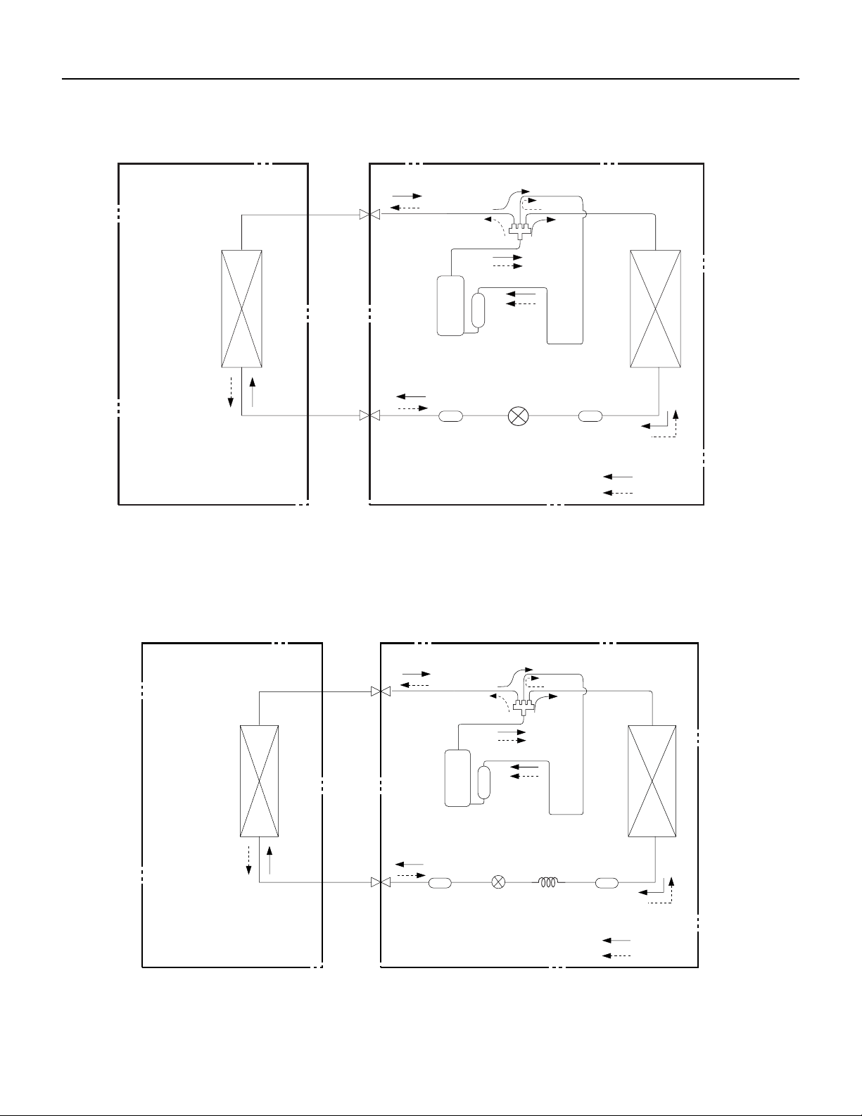
45 PB
OPERATION
Figure 302
9-12K Refrigerant System Diagram
Figure 303
18-24K Refrigerant System Diagram
Indoor unit
COOLING
HEATING
4-Way valve
Discharge
Suction
Outdoor unit
Heat
exchanger
Heat
(evaporator)
Valve
(condenser)
exchanger
Valve
side
Liquid pipe
Gas pipe
side
Accumlator
Compressor
Strainer
Electron
Strainer
expansion
valve
Indoor unit
COOLING
HEATING
Discharge
Outdoor unit
Suction
4-Way valve
Heat
exchanger
(evaporator)
Heat
exchanger
(condenser)
Valve
Valve
side
Liquid pipe
Gas pipe
side
Strainer
Strainer
Capillary
Accumlator
Electron
expansion
Compressor
valve
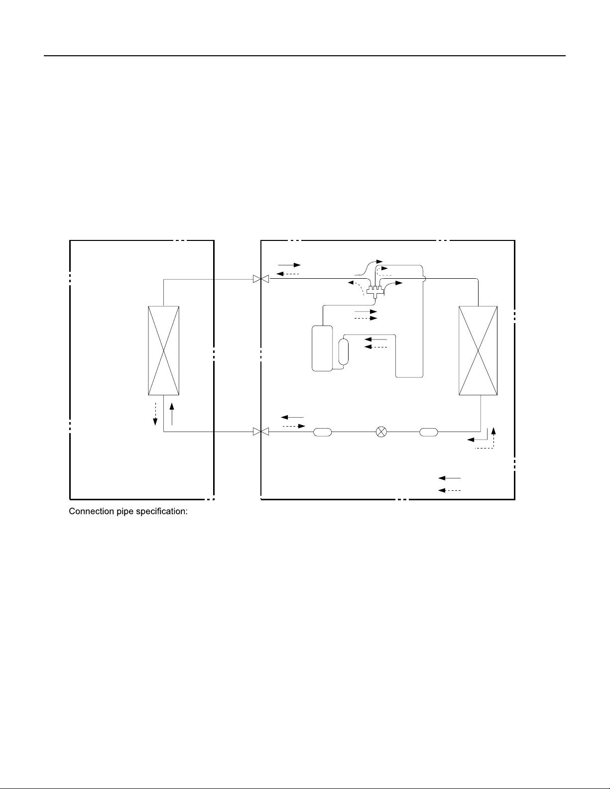
46 PB
OPERATION
Figure 304
36K Refrigerant System Diagram
COOLING
HEATING
4-Way valve
Discharge
Suction
Heat
exchanger
(evaporator)
Heat
exchanger
(condenser)
Valve
Valve
side
Liquid pipe
Gas pipe
side
Electron
Strainer
expansion
valve
Strainer
Accumlator
Compressor
Liquid pipe:1/4 inch
Gas pipe:5/8 inch
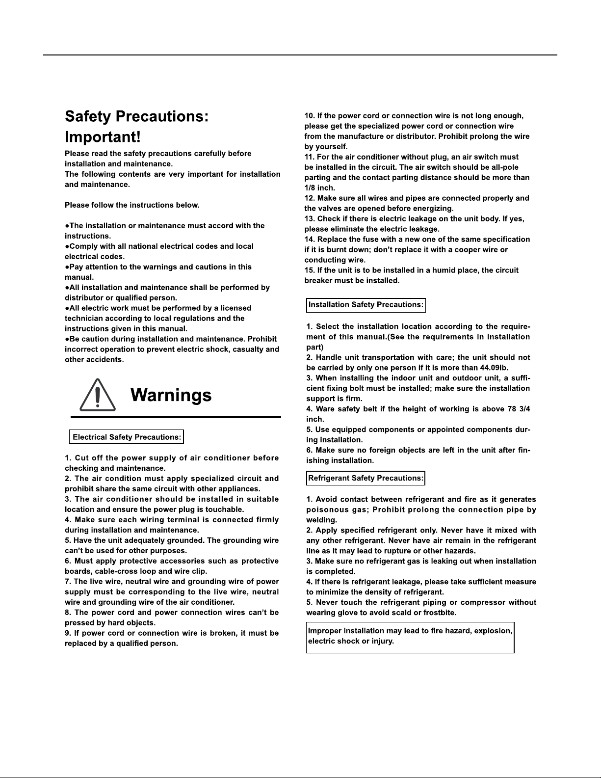
47 PB
INSTALLATION
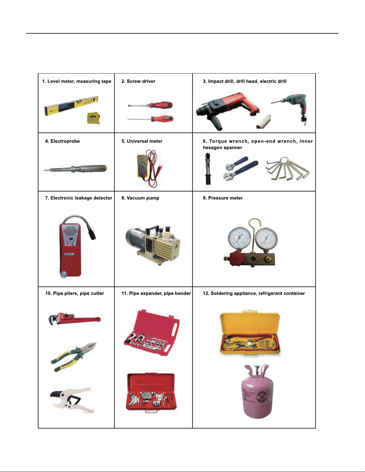
48 PB
INSTALLATION
Installation Tools
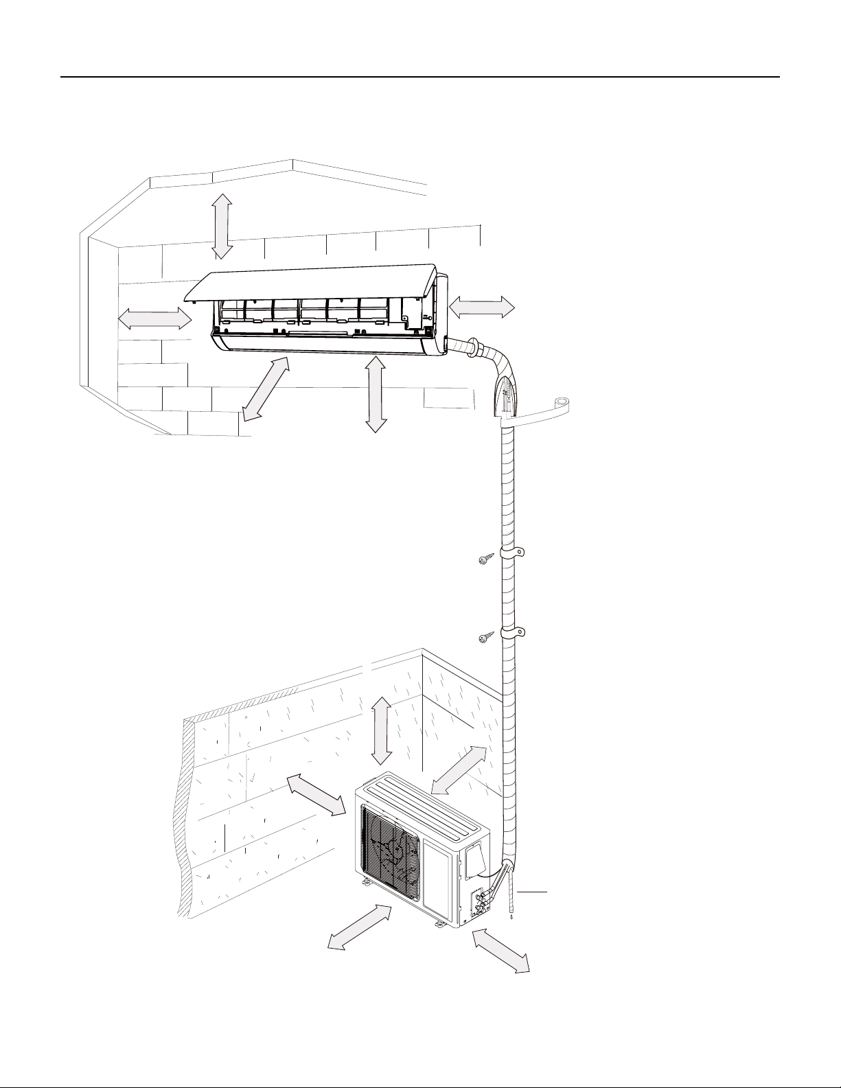
49 PB
INSTALLATION
Installation Dimension Diagram
Space to the ceiling
Space to the wall
At least 5 inches(”)
At least 78 inches(”)
At least 4 inches(”)
At least 4 inches(”)
Space to the wall
Space to the obstruction
roolf eht ot ecapS
At least 60 inches(”)
Space to the obstructio
At least 28 inches(”)
At least
Space to the wall
12 inches(”)
At least 24 inches(”)
Space to the obstruction
At least 12 inches(”)
Drainage pipe
Space to the obstruction
At least 24 inches(”)
Space to the obstruction
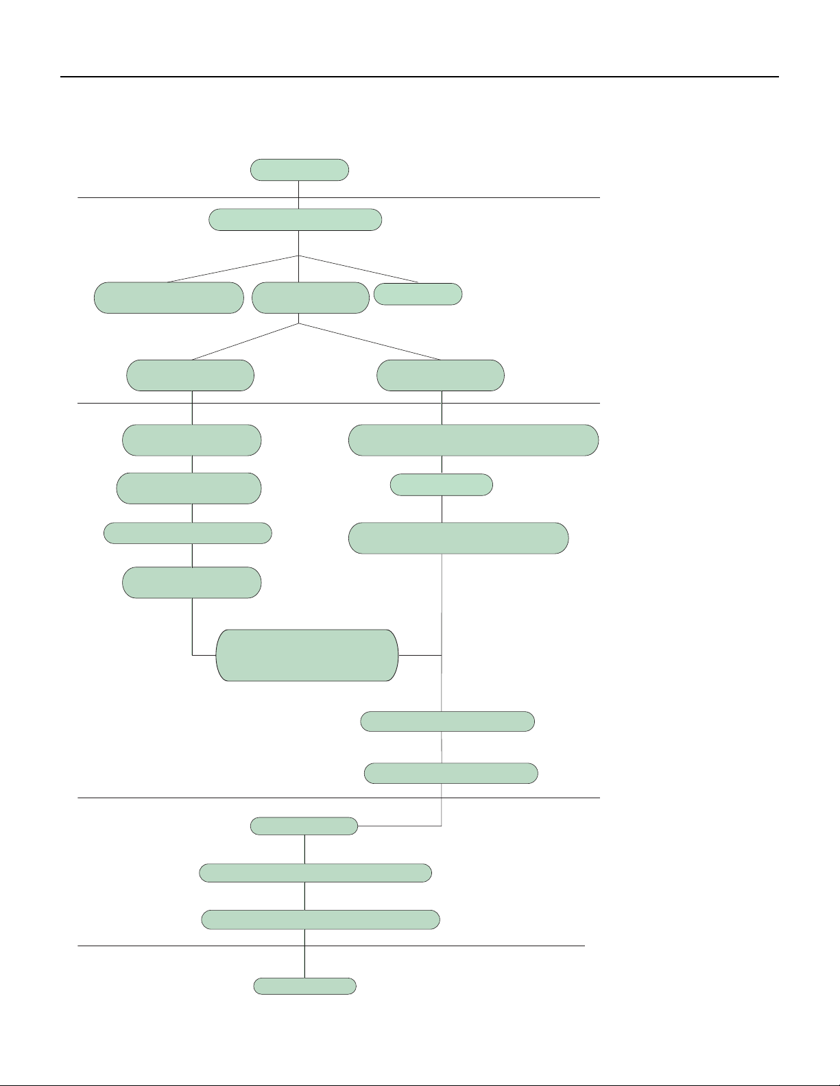
50 PB
INSTALLATION
Installation Work Flow
Preparation before installation
Prepare tools
Read the requirements
for electric connection
select installation
location
Select indoor unit
installation location
Install wall-mounting
frame, drill wall holes
Connect wires of indoor unit
Connect pipes of indoor
unit and drainage pipe
Connect wires of outdoor unit
Bind up pipes and
hang the indoor unit
Make the bound pipes pass
through the wall hole and then
connect outdoor unit
Neaten the pipes
Vacuum pumping and leakage detection
Check after installation and test operation
Finish installation
Select outdoor unit
installation location
Install the support of outdoor unit
(select it according to the actual situation)
Connect pipes of outdoor unit
Install drainage joint of outdoor unit
(only for cooling and heating unit)
Start installation
Fix outdoor unit

51 PB
INSTALLATION
Installation Parts Checklist
1. Indoor Unit
2. Outdoor Unit
3. Connection Pipe
4. Drainage pipe
5. Wall Mounting Frame
6. Connecting Cable (power cord)
7. Wall Pipe
8. Sealing gim
9. Wrapping Tape
10. Outdoor unit support
11. Fixing screw
12. Drainage plug (cooling and heating unit)
13. Owner’s Manual
14. Remote Control
Selection of Installation Location
Basic Requirement
Installing the unit in the following places may cause malfunction. If it is unavoidable, please consult the local dealer:
1. Places with strong heat sources, vapors, flammable or explosive gas, or volatile objects spread in the air.
2. Places with high‑frequency devices (such as welding machine, medical equipment).
3. Places with oil or fumes in the air.
4. Places with sulfureted gas.
Indoor Unit
1. There should be no obstruction near air inlet and air outlet.
2. Select a location where the condensation water can be dispersed easily and won’t affect other people.
3. Select a location which is convenient to connect the outdoor unit and near the power socket.
4. Select a location which is out of reach for children.
5.The location should be able to withstand the weight of indoor unit and won’t increase noise and vibration.
6. The appliance must be installed 78 inches above the floor.
7. Don’t install the indoor unit right above electric appliances.
8. The appliance shall not be installed in the laundry.

52 PB
INSTALLATION
Outdoor Unit
1. Select a location where the noise and outflow air emitted by the outdoor unit will not affect neighborhood.
2. The location should be well ventilated and dry, in which the outdoor unit won’t be exposed directly to sunlight or strong wind.
3. The location should be able to withstand the weight of outdoor unit.
4. Make sure that the installation follows the requirement of installation dimension diagram.
5. Select a location which is out of reach for children and far away from animals or plants.If it is unavoidable, please add fence for safety
purpose.
Electrical connection Requirements
Safety Precaution
1. Must follow the electric safety regulations when installing the unit.
2. According to the local safety regulations, use qualified power supply circuit and air switch.
3. Make sure the power supply matches with the requirement of air conditioner. Unstable power supply or incorrect
wiring may result in electric shock,fire hazard or malfunction. Please install proper power supply cables before using the air
conditioner.
4. Properly connect the live wire, neutral wire and grounding wire of power socket.
5. Be sure to cut off the power supply before proceeding any work related to electricity and safety.
6. Do not put through the power before finishing installation.
7. For appliances with type Y attachment,the instructions shall contain the substance of thefollowing.If the supply cord is
damaged, it must be replaced by the manufacturer,its service agent or similarly qualified persons in order to avoid a hazard.
8. The temperature of refrigerant circuit will be high, please keep the interconnection cable away from the copper tube.
Grounding Requirements
1. The air conditioner is first class electric appliance. It must be properly grounded with a specialized grounding
device by a professional. Please make sure it is always grounded effectively, otherwise it may cause electric shock.
2. The yellow‑green wire in air conditioner is grounding wire, which can’t be used for other purposes.
3. The grounding resistance should comply with national electric safety regulations.
4. The appliance must be positioned so that the plug is accessible.
5. An all‑pole disconnection switch having a contact separation of at least 3mm in all poles should be connected in fixed wiring.
6. Include an air switch with suitable capacity, please note the following table. Air switch should be included mag
net buckle and heating buckle function, it can protect the circuit‑short and overload.
CAUTION
Do not rely on the fuse
alone for protection of the
circuit
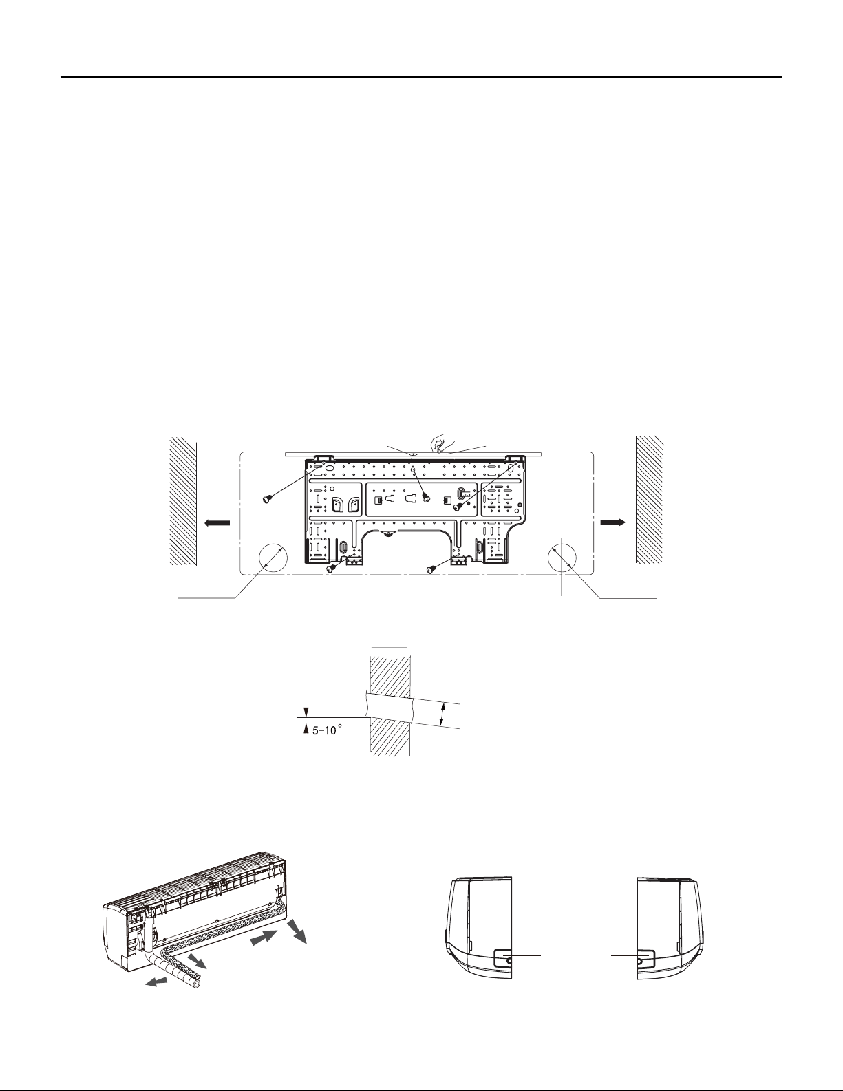
53 PB
INSTALLATION
Installation of Indoor Unit
Install Wall Mounting Frame
1. Hang the wall‑mounting frame on the wall; adjust it in horizontal position with the level meter and then point out the screw fixing holes
on the wall.
2. Drill the screw fixing holes on the wall with impact drill (the specification of drill head should be the same as the plastic expansion
particle) and then fill the plastic expansion particles in the holes.
3. Fix the wall‑mounting frame on the wall with tapping screws (ST4.2X25TA) and then check if the frame is firmly installed by pulling the
frame. If the plastic expansion particle is loose, please drill another fixing hole nearby.
4. Choose the position of piping hole according to the direction of outlet pipe. The position of piping hole should be a little
lower than the wall‑mounted frame.(As show in Fig.1)
5. Open a piping hole with the diameter of 2 3/4inch on the selected outlet pipe position.In order to drain smoothly, slant the
piping hole on the wall slightly downward to the outdoor side with the gradient of 5‑10°.(As show in Fig.2)
Note:
1. Pay attention to dust prevention and take relevant safety measures when opening the hole.
2. The plastic expansion particles are not provided and should be bought locally.
Fig.1
6inch
6inch
Wall
Wall
Mark on the middle of it
Gradienter
Left
Right
(Rear piping hole) (Rear piping hole)
Space
to the
wall
above
Space
to the
wall
above
Φ2 1/16inch
Φ2 3/16inch
Φ2 3/4inch
Φ2 1/16inch
Φ2 3/16inch
Φ2 3/4inch
Φ2 1/16inch
Φ2 3/16inch
Φ2 3/4inch
Indoor
Outdoor
Fig.2
Outlet Pipe
1. The pipe can be led out in the direction of right, rear right, left or rear left.(As show in Fig.3)
2. When selecting leading out the pipe from left or right, please cut off the corresponding hole on the bottom case.(As show in Fig.4)
Left
Rear left
Right
Rear right
Fig. 3
Cut off
the hole
Left Right
g. 4
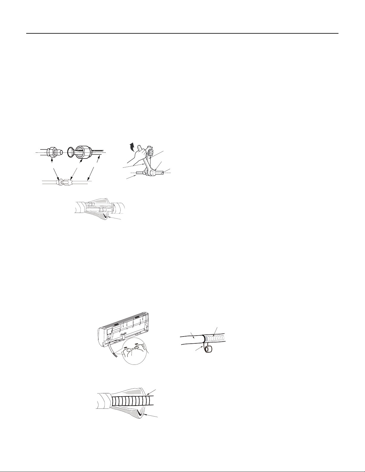
54 PB
INSTALLATION
Installation of Indoor Unit
Connect the Pipe of the Indoor Unit
1. Aim the pipe joint at the corresponding bellmouth.(As show in Fig.5)
2. Pretightening the union nut with hand.
3. Adjust the torque force by referring to Figure 22a. Place the open‑end wrench on the pipe joint and place the
torque wrench on the union nut. Tighten the union nut with torque wrench.(As show in Fig.6)
4. Wrap the indoor pipe and joint of connection pipe with insulating pipe, and then wrap it with tape.(As show in Fig.7)
Insulating pipe
Torque wrench
Open-end
wrench
Indoor pipe
Pipe
Union nut
Pipe joint Union nut
Pipe
Refer to the following table for wrench moment of force
Fig.5 Fig.6
Fig.7
Hex nut diameter(inch) Tightening torque(ft∙Ibf)
Φ1/4 11~14.7
Φ3/8 22.8~29.5
Φ1/2 33.2~40.6
Φ5/8 44.3~47.9
Φ3/4 51.6~55.3
Install Drain Hose
1. Connect the drain hose to the outlet pipe of indoor unit.(As show in Fig.8)
2. Bind the joint with tape.(As show in Fig.9)
Note:
1. Add insulating pipe in the indoor drain hose in order to prevent condensation. (As show in Fig.10)
2. The plastic expansion particles are not provided.
Drain hose
Insulating pipe
Fig.10
Outlet
pipe
Drain hose
Drain hose
Tape
Outlet pipe
Fig.8
Fig.9
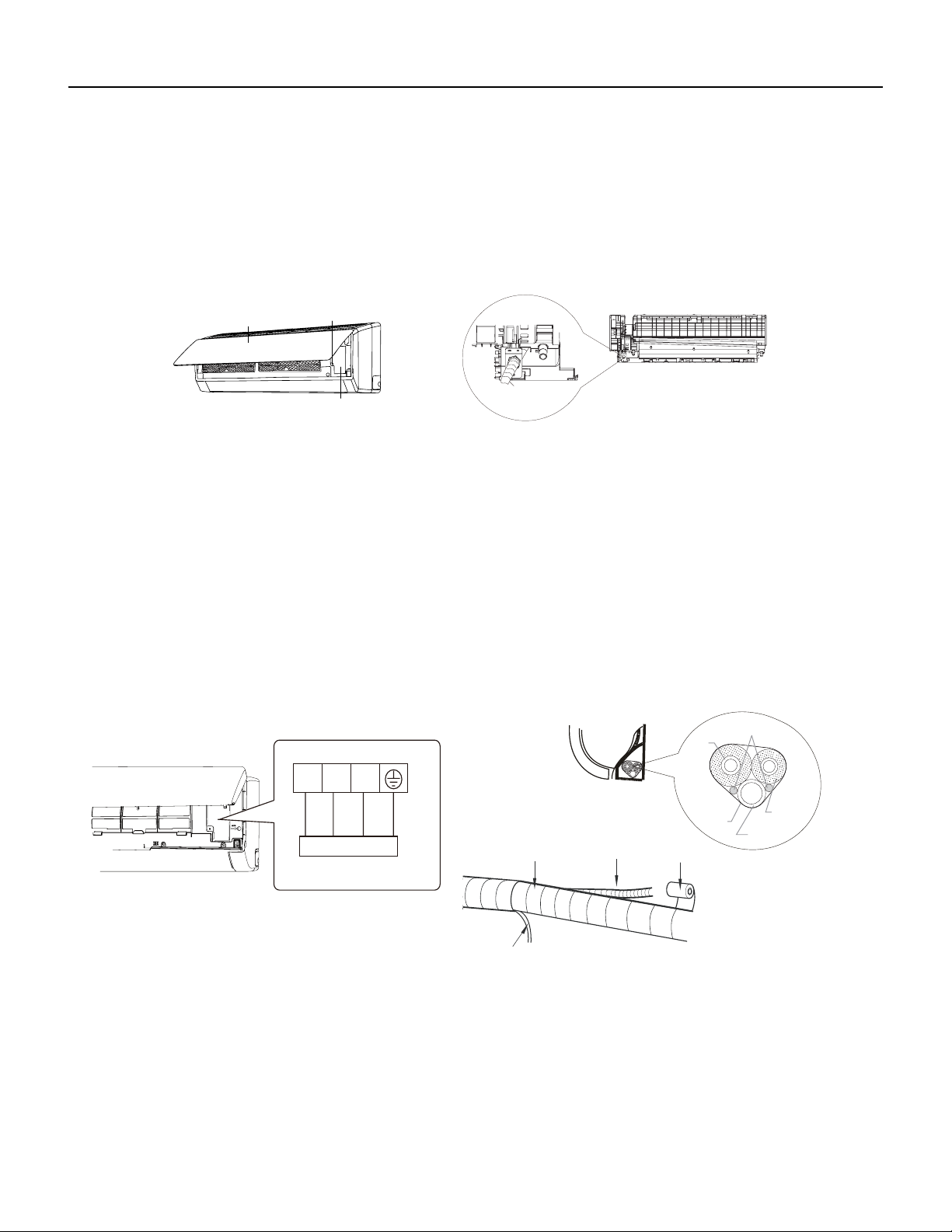
55 PB
Connect Wire of Indoor Unit
1. Open the panel, remove the screw on the wiring cover and then take down the cover.(As show in Fig.11)
2. Fix the wire crossing board on connection wire sleeve at the bottom case; let the connection wire sleeve go through
the wire crossing hole at the back of indoor unit, and then pull it out from the front.(As show in Fig.12)
INSTALLATION
Installation of Indoor Unit
Fig.11
Wiring cover
Screw
Panel
connection wire sleeve
Fig.12
3. Remove the wire clip; connect the power connection wire to the wiring terminal; tighten the screw and then fix the power connection wire
with wire clip.(As show in Fig.13)
4. Put wiring cover back and then tighten the screw.
5. Close the panel.
NOTE:
All wires of indoor unit and outdoor unit should be connected by a professional.
If the length of power connection wire is insufficient, please contact the supplier for a new one. Avoid extending the wire by
yourself.
For the air conditioner with plug, the plug should be reachable after finishing installation.
For the air conditioner without plug, an air switch must be installed in the line. The air switch should be all‑pole parting and
the contact parting distance should be more than 1/8inch.
N(1) 2 3
yellow-
green
Outdoor unit connection
Fig.13
Indoor unit
Gas
pipe
Indoor and
outdoor power cord
Liquid
pipe
Drain hose
Band
Connection pipe
Indoor power cord
Drain hose
Band
Fig.14
Fig.15
Bind Up Pipe
1. Bind up the connection pipe, power cord and drain hose with the band.(As show in Fig.14)
2. Reserve a certain length of drain hose and power cord for installation when binding them. When binding to a certain degree, separate the
indoor power and then separate the drain hose.(As show in Fig.15)
3. Bind them evenly.
4. The liquid pipe and gas pipe should be bound separately at the end.
5. The power cord and control wire can’t be crossed or winding.
6. The drain hose should be bound at the bottom.
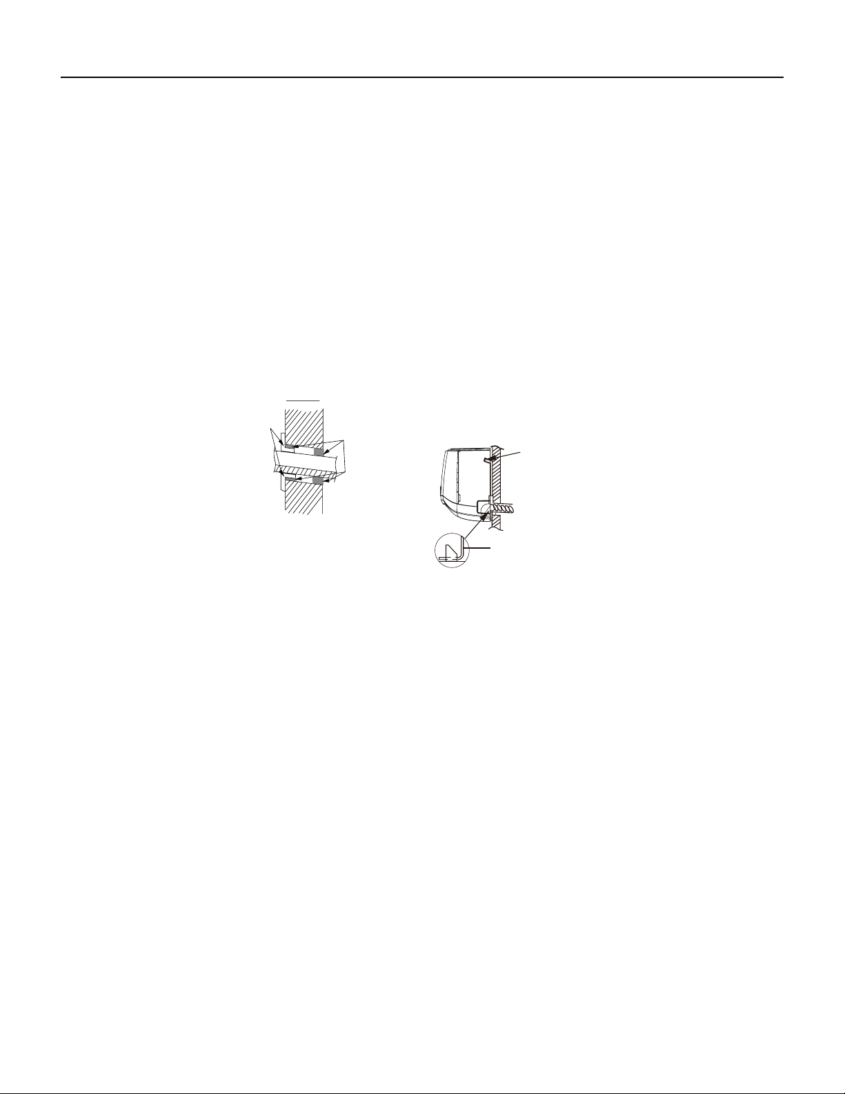
56 PB
INSTALLATION
Installation of Indoor Unit
Hang the Indoor Unit
1. Put the bound pipes in the wall pipe and then make them pass through the wall hole.
2. Hang the indoor unit on the wall‑mounting frame.
3. Stuff the gap between pipes and wall hole with sealing gum.
4. Fix the wall pipe. (As show in Fig.16)
5. Check if the indoor unit is installed firmly and closed to the wall.(As show in Fig.17)
NOTE
Do not bend the drain hose too excessively in order to prevent blocking.
Indoor
Outdoor
Wall pipe
Sealing gum
Upper hook
Lower hook of
wall-mounting frame
Fig.16
Fig.17
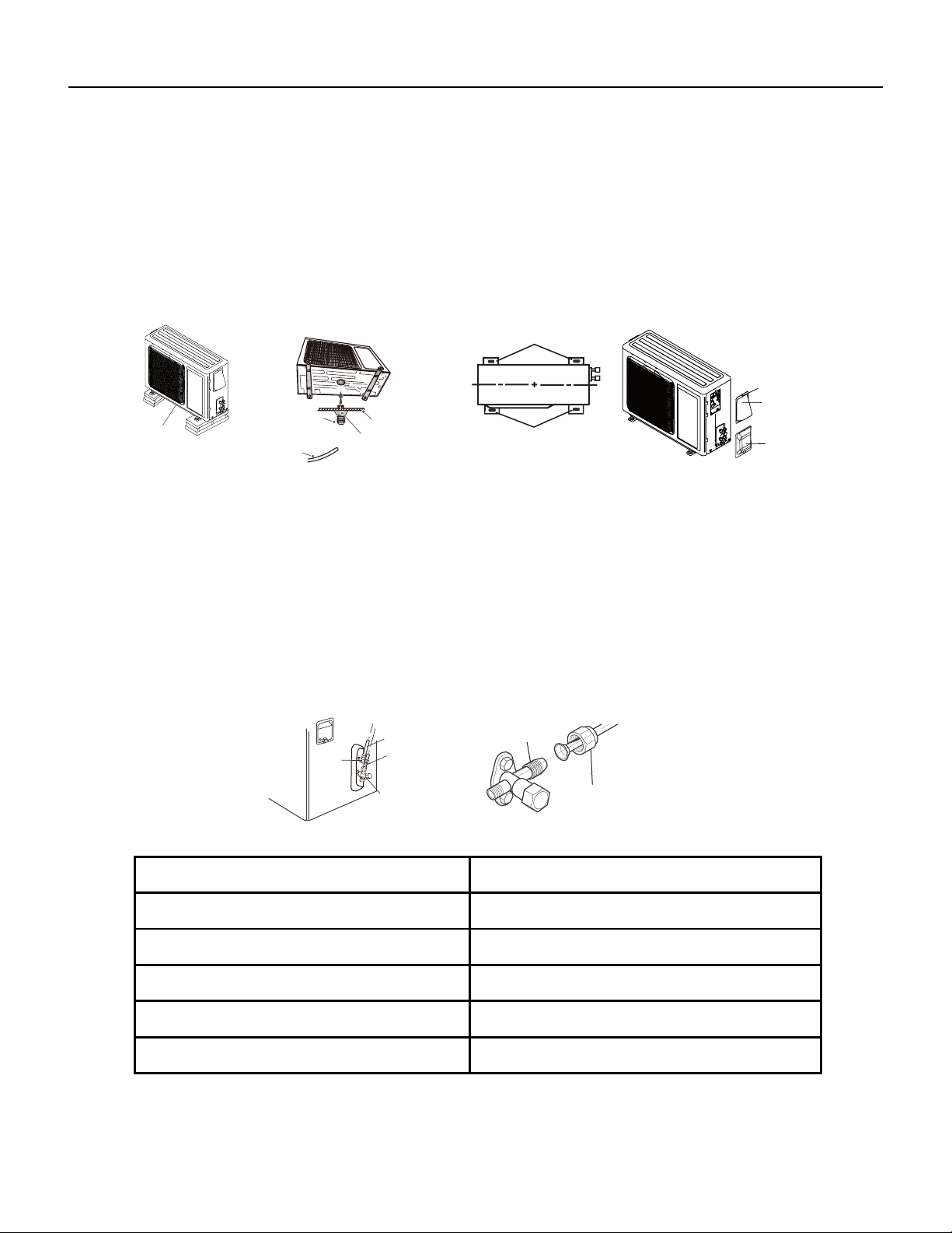
57 PB
INSTALLATION
Installation of the Outdoor Unit
Install the Outdoor Support
1. Select installation location according to the house structure.
2. Fix the support of outdoor unit on the selected location with expansion screws.
Notes
1. Take sufficient protective measures when installing the outdoor unit.
2. Make sure the support can withstand at least four times the unit weight.
3. The outdoor unit should be installed at least 1 1/6inch above the floor in order to install drain joint.(As show in
Fig.18)
Drain hose
Chassis
Outdoor drain joint
Drain vent
Fig.18 Fig.19
At least 1 1/6 inch
above the oor
Foot holes
Foot holes
Fig.20
Fig.21
Screw
Cable Cross
Plate Sub-assy
Valve Cover
Install Drain Joint ( For Colling and Heating Unit Only)
1. Connect the outdoor drain joint into the hole on the chassis.
2. Connect the drain hose into the drain vent. (As show in Fig.19)
Fix the Outdoor Unit
1. Place the outdoor unit on the support.
2. Fix the foot holes of outdoor unit with bolts.(As show in Fig.20)
Connect Indoor and Outdoor Pipes
1. Remove the screw on the right cable cross plate sub‑assy and valve cover of outdoor unit and then remove the
cable cross plate sub‑assy and valve cover.(As show in Fig.21)
2. Remove the screw cap of valve and aim the pipe joint at the bellmouth of pipe.(As show in Fig.22)
3. Pretightening the union nut with hand.
4. Tighten the union nut with torque wrench .
Refer to the figure 22a for wrench moment of force
gas pipe
Liquid pipe
Liquid
valve
gas valve
Union nut
Pipe joint
Fig.22
Hex nut diameter(inch) Tightening torque(ft∙Ibf)
Φ1/4 11~14.7
Φ3/8 22.8~29.5
Φ1/2 33.2~40.6
Φ5/8 44.3~47.9
Φ3/4 51.6~55.3
Fig. 22a
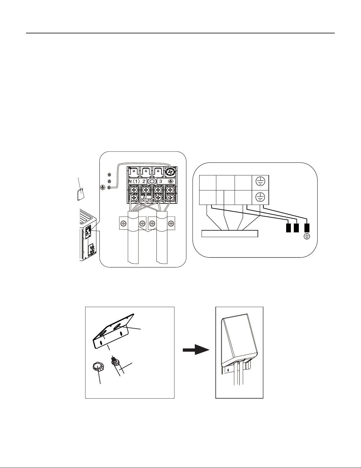
58 PB
INSTALLATION
Installation of the Outdoor Unit
Connect Outdoor Electric Wire
1. Put power connection wire and power wire through the wire‑‑passing hole.
2. Remove the wire clip; connect the power connection wire and power wire to the wiring terminal; fix them with screws.(As
show in Fig.23)
3. Fix the power connection wire and power wire with wire clip.
4. Install the cable cross plate sub‑assy.
Notes
1. After tightening the screw, pull the power cord slightly to check if it is firm.
2. Never cut the power connection wire to prolong or shorten the distance.
3. The connecting wire and connection pipe cannnot touch each other.
4. Top cover of outdoor unit and electric box assembly should be fixed by the screw. Otherwise, it can cause a fire, or short
circuit caused by water or dust.
Fig.23
cord clamp
cable cross
plate sub-assy
power connect wire
power wire
N(1)
N
N
L
L
32
Indoor unit connection
wire pipe
wire-passing
hole
Fixed nut
Finish
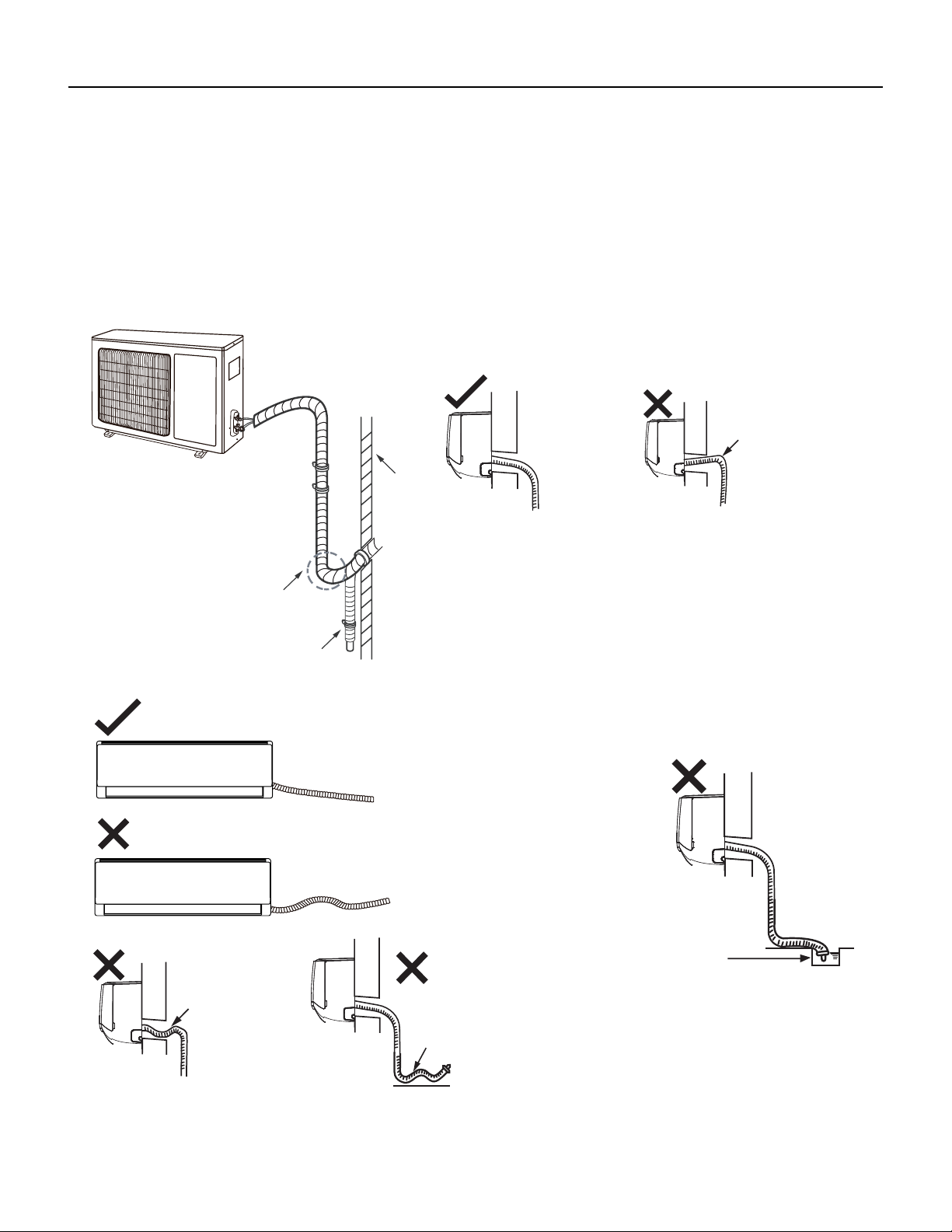
59 PB
INSTALLATION
Installation of the Outdoor Unit
Neaten the Pipes
1. The pipes should be placed along the wall, bent reasonably and hidden possibly. Min. semidiameter of bending the pipe is 4 inch.
2. If the outdoor unit is higher than the wall hole, you must set a U‑shaped curve in the pipe before pipe goes into the room, in order to
prevent rain from getting into the room. (As show in Fig.24)
Notes:
1. The through‑wall height of drain hose shouldn’t be higher than the outlet pipe hole of indoor unit. (As show in Fig.25)
2.Slant the drain hose slightly downwards. The drain hose can’t be curved, raised and fluctuant, etc. (As show in Fig.26)
3. The water outlet can’t be placed in water in order to drain smoothly.(As show in Fig.27)
The drain hos
can't raise
upwards
Fig.24
Fig.25
U-shaped curve
Wall
Drain hose
The drain hose can't be uctuant
The drain hose
can't be uctuant
The water
outlet can't be
uctuant
The water outlet
can't be placed
in water
Fig.26
Fig.27

60 PB
INSTALLATION
Leak Check, Evacuation, and Charging (Triple Evacuation)
Friedrich requires all installations are Leak Checked and Evacuated in accordance to the “triple evacuation” process. This process pro‑
motes a dry tight refrigeration system before opening the service valves. It recommended that a single port refrigeration manifold and
hoses rated over 800psi be used. Refrigeration hose valves, along with a vacuum pump and micron gauge, must be used to ensure the
system can be vacuumed and held under 500 microns. Check all equipment and hoses for proper usage and leaks before beginning.
1. 1st Nitrogen Pressure Test:
Ensure all refrigeration connections are properly flared, secured, and torqued to their respective settings. Pressurize the
system with nitrogen to 550psi. Soap all connections with an approved refrigerant leak detection solution. The pressure in
the system must hold for one hour respective to the environmental conditions and should not vary less than 540psi. If
pressure can not be adequate held, check integrity of flares and torque specifications. Once pressure is held adequately,
purge the nitrogen charge to system pressure of 5‑10psi. DO NOT RETURN TO ATMOSPHERIC PRESSURE.
2. 1st Vacuum Micron Test:
Connect hoses and vacuum pump to the outdoor unit as shown in Fig.28. Start the vacuum pump and vacuum to 1000
microns. Close the valve to the vacuum pump and check for micron rise for 15 minutes. If microns rise to near
atmospheric pressure, there is a potential leak; follow Section 8.7.A. If microns rise over 5000, the system is very wet and
will require further nitrogen purges.
3. 2nd Nitrogen Break:
Once the system holds below 5000 microns, reconnect the nitrogen tank break the system vacuum with 30‑50psi of
nitrogen. Wait 5 minutes, then purge to 5‑10psi. DO NOT RETURN TO ATMOSPHERIC PRESSURE.
4. 2nd Vacuum Micron Test:
Reconnect vacuum pump and gauge and begin evacuation. Vacuum system to 500 microns. Close vacuum valve
and check for micron rise. Vacuum should hold under 1000 microns. Repeat 8.7.C and 8.7.D until achieved.
5. 3rd Nitrogen Break:
Once the system holds below 1000 microns, reconnect the nitrogen tank break the system vacuum with 30‑50psi of
nitrogen. Wait 5 minutes, then purge to 5‑10psi. DO NOT RETURN TO ATMOSPHERIC PRESSURE.
6. 3rd Final Vacuum Micron Test:
Reconnect vacuum pump and gauge and begin evacuation. Vacuum system to 300 microns. Close vacuum valve
and check for micron rise. Vacuum should hold under 500 microns. Repeat 8.7.C and 8.7.D until achieved. Once held
under 500 microns, the system is considered dry and tight.
7. Charging the system:
Unscrew Service Valve Caps to expose the inner hexagon head. Use an allen‑head spanner or service wrench with
appropriate adapter to release the refrigerant into the system. If the calculated line set length is over 24.9ft, weight
i n the additional charge with an approved refrigerant scale as needed (Fig.28B).
61 PB
INSTALLATION
Leak Check, Evacuation, and Charging (Triple Evacuation)
WAIT
EVACUATE
BREAK VACUUM WITH DRY NITROGEN
CHARGE SYSTEM
EVACUATE
WAIT
EVACUATE
CHECK FOR TIGHT, DRY SYSTEM
(IF IT HOLDS A VACUUM)
BREAK VACUUM WITH DRY NITROGEN
62 PB
INSTALLATION
Checklist and Operation Test
Check Unit following Installation
No. Items to be checked Possible malfunction
1
Has the unit been
installed firmly?
2
The unit may drop, shake or
emit noise.
Have you done the
refrigerant leakage test?
3
It may cause insufficient cooling
(heating) capacity.
Is heat insulation of
pipeline sufficient?
4
It may cause condensation and
water dripping.
Is water drained well?
5
It may cause condensation and
water dripping.
6
It may cause malfunction or
damage the parts.
Is the voltage of power
supply according to the
voltage marked on the
nameplate?
7
Is electric wiring and
pipeline installed
correctly?
It may cause malfunction or
damage the parts.
It may cause electric leakage.
Is the unit grounded
securely?
8
Does the wiring
follow the specifications?
9
It may cause malfunction or
damage the parts.
Is there any obstruction
in air inlet and air outlet?
10
It may cause insufficient cooling
(heating).
11
It may cause malfunction or
damaging the parts.
Dust and debris not
after installation?
removed after
The gas valve and liquid
valve of connection pipe
are open completely?
It may cause insufficient cooling
(heating) capacity.
Test Operation
1. Preparation of Test Operation
The client approves the air conditioner installation.
Specify the important notes for air conditioner to the client.
2, Method of test operation
Turn on the power, press ON/OFF button on the remote controller to start operation.
Press MODE button to select AUTO, COOL, DRY, FAN and HEAT to check whether the operation is normal or
not.
If the ambient temperature is lower than 60.8°F, the air conditioner can’t start cooling.
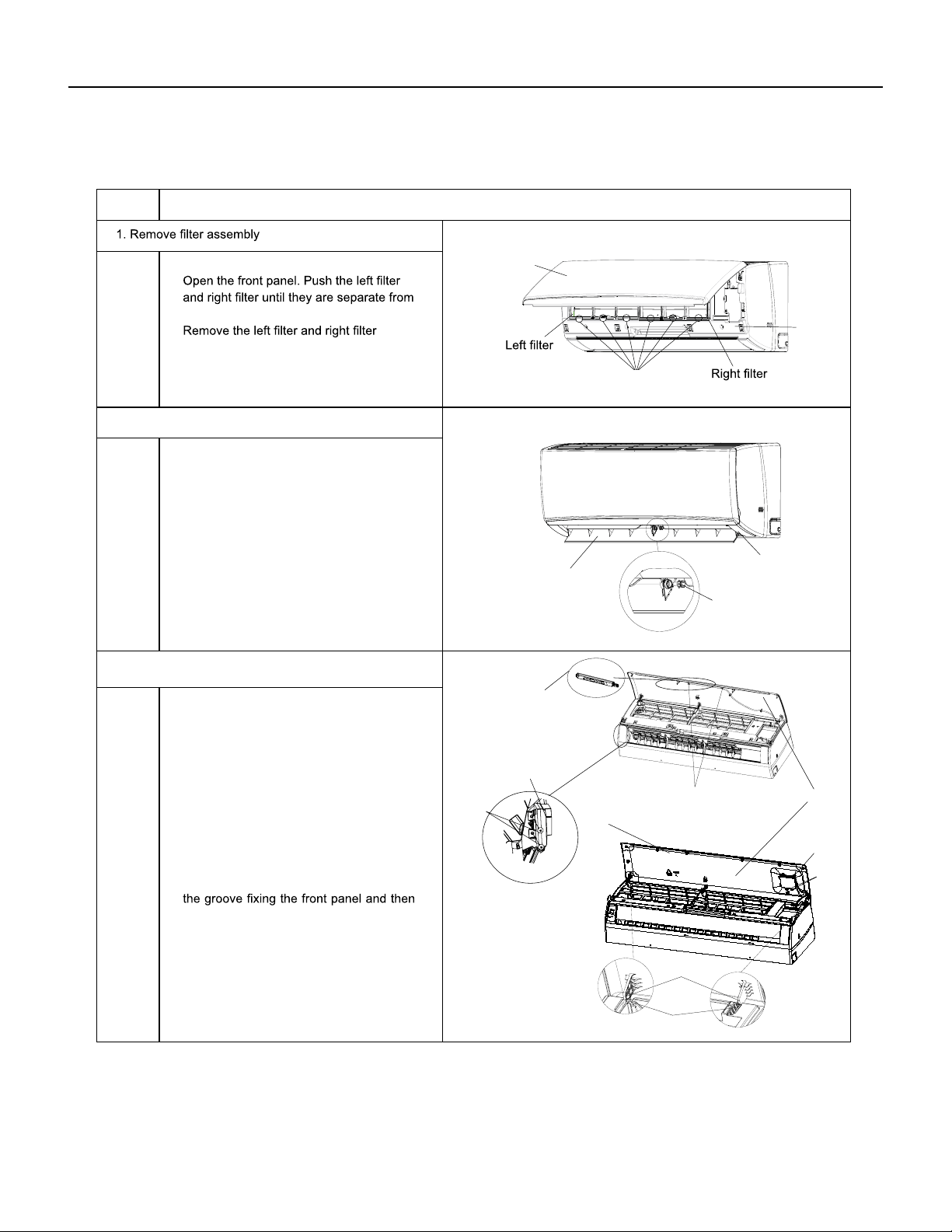
63 PB
REMOVAL
Indoor Unit
a
b
Axile bush
Horizontal louver
Location of step motor
ProcedureStep
2. Remove horizontal louver
Front panel
Front
case
Groove
Push out the axile bush on horizontal
louver. Bend the horizontal louver with
hand and then separate the horizontal
louver from the crankshaft of step motor
to remove it.
the groove on the front panel.
respectively.
that are locking the display board.
(1)A1 display: Screw off the 2 screws that
are locking the display board. Separate
the display board from the front panel.
(2)A3/A5 display: Screw off the 2 screws
3. Remove panel
Separate the panel rotation shaft from
removes the front panel.
Panel
Screws
Screws
Screws
A1 display
A5 display
A3/A6 display
Front panel
Panel rotation
Groove
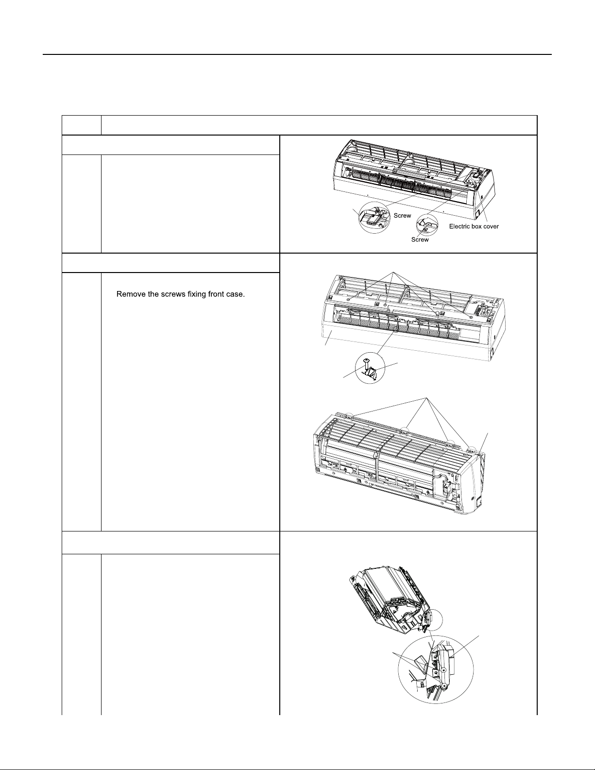
64 PB
REMOVAL
Indoor Unit
a
b
Note:
Screw off the 2 screws that are locking
the display board.
1.Open the screw caps before removing
the screws around the air outlet.
2.The quantity of screws fixing the front
case sub-assy is different for different
models.
5. Remove front case sub-assy
6. Remove display
Bottom case
Front case
sub-assy
Display
Screws
Clasp
Screw caps
Loosen the connection clasps between
front case sub-assy and bottom case. Lift
up the front case sub-assy and take it out.
Screws
Screw
Detecting plate(WIFI)
2
ProcedureStep
4. Remove electric box cover 2 and detecting plate(WIFI)
Remove the screws on the electric box
cover 2 and detecting plate(WIFI), then
remove the electric box cover 2 and
detecting plate(WIFI).
Note:the position of detection board(WIFI)
may be different for different models.
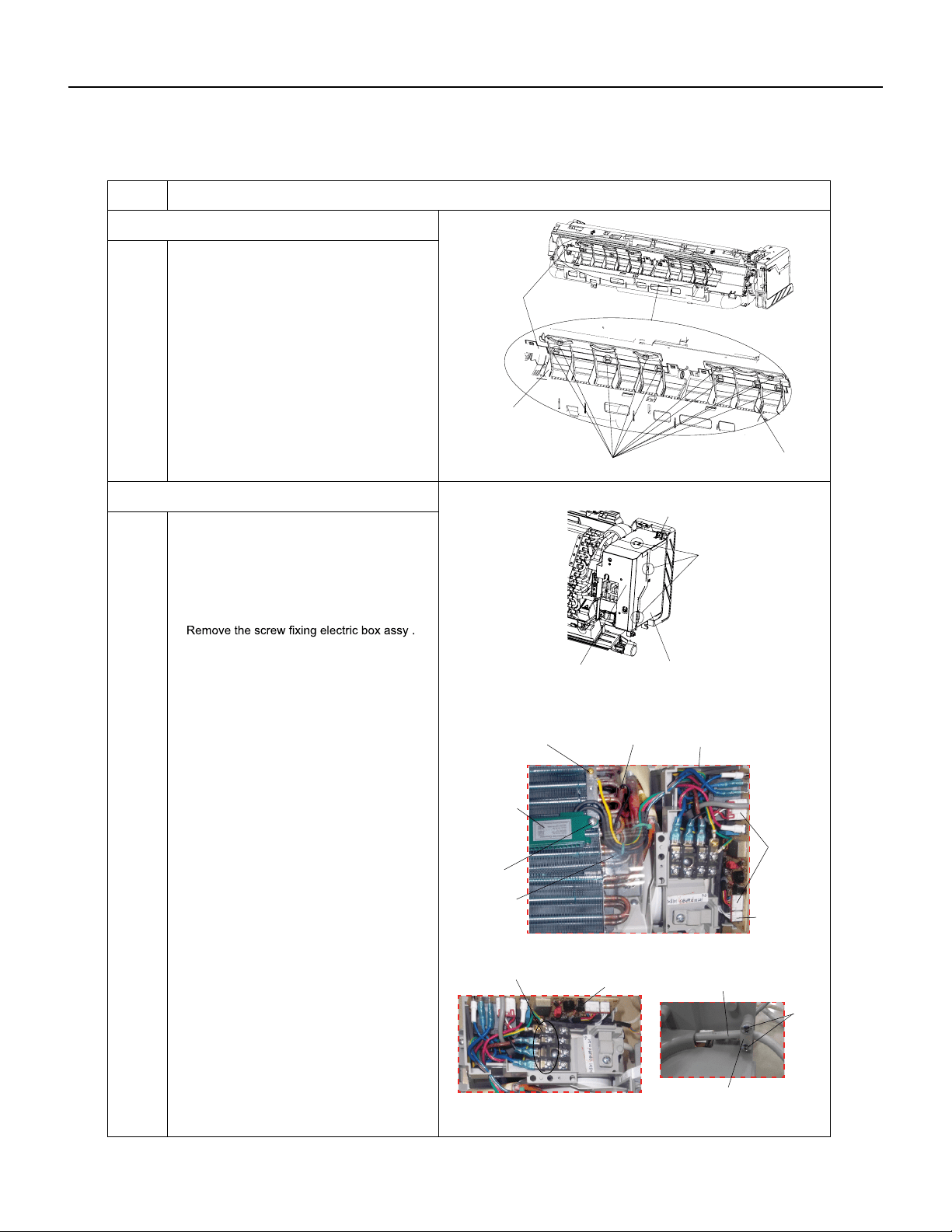
65 PB
REMOVAL
Indoor Unit
a
b
c
ProcedureSteps
Loosen the connection clasps between
shield cover of electric box sub-assy and
electric box, and then remove the shield
cover of electric box sub-assy.
①
Take off the water retaining sheet.
Remove the cold plasma generator by
screwing off the locking screw on the
generator.
②
Take off the indoor tube temperature
sensor.
③
Screw off 1 grounding screw.
④
Remove the wiring terminals of motor and
stepping motor.
⑤
Remove the electric box assy.
8. Remove electric box assy
Electric box
Twist off the screws that are locking
each lead wire and rotate the electric
box assy.
Twist off the screws that are locking the
wire clip. Loosen the power cord and
remove it's wiring terminal. Lift up the
main board and take it off.
Electric box assy
Clasps
Shield cover of electric
box sub-assy
Cold plasma
generator
Water retaining
sheet
Grounding screw
Screw
Power cord
Wire clip
Screws
Main board
Screw
Indoor tube
temperature
sensor
Wiring
terminal
of motor
Wiring
terminal
of stepping
motor
Screw
Vertical
louver
Vertical
louver
Clasps
Bottom
case
7. Remove vertical louver
Loosen the connection clasps between
vertical louver and bottom case to remove
vertical louver.
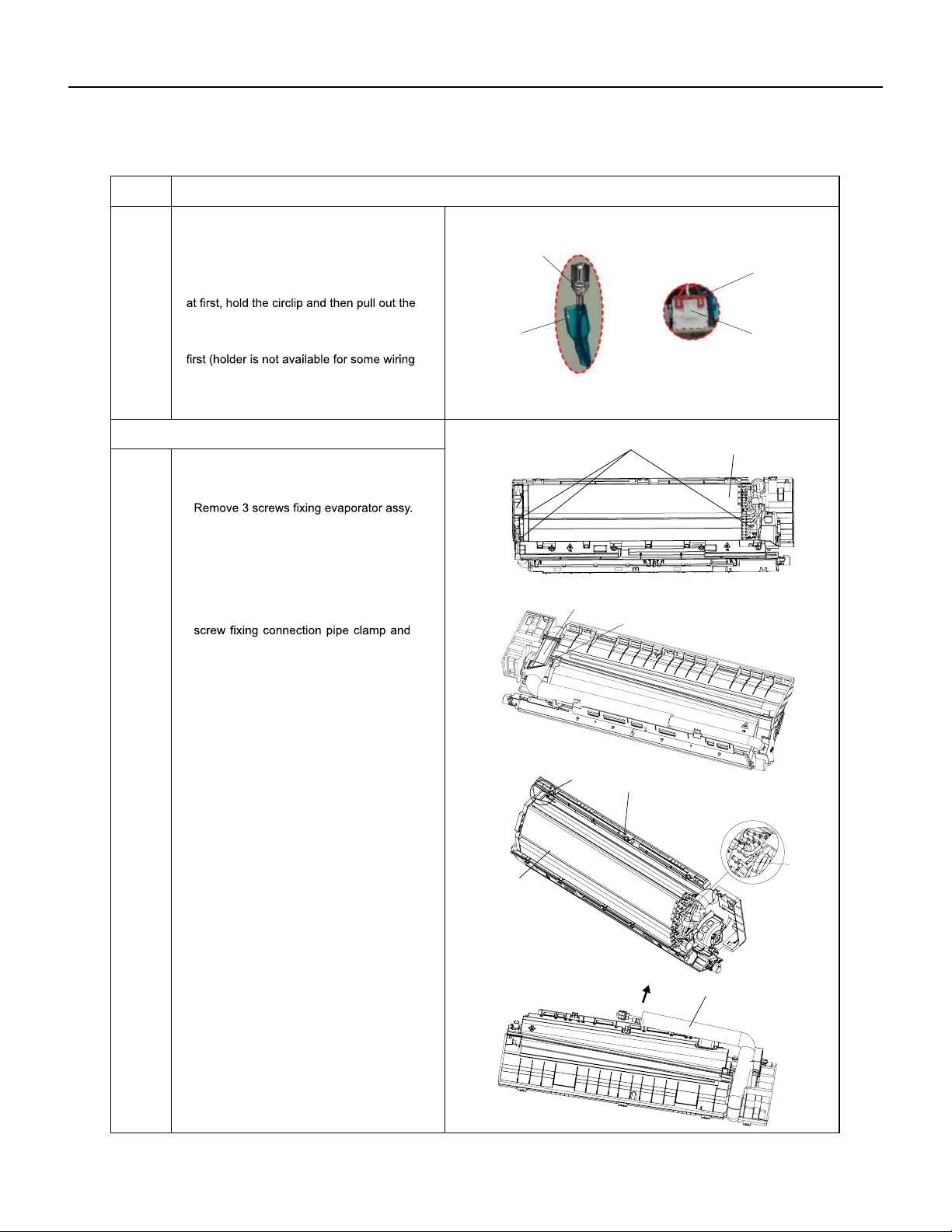
66 PB
REMOVAL
Indoor Unit
a
c
d
b
Instruction: Some wiring terminal of this
product is with lock catch and other devices.
The pulling method is as below:
First remove the left side of the evaporator
from the groove of bottom case and then
remove the right side from the clasp on
the bottom case.
Circlip
Soft sheath
①
Remove the soft sheath for some terminals
terminals.
②
Pull out the holder for some terminals at
terminal), hold the connector and then pull the
terminal.
Holder
Connector
ProcedureSteps
9. Remove evaporator assy
Screws
Connection pipe clamp
Evaporator assy
Evaporator assy
Screw
Groove
Bottom case
Clasp
Connection pipe
At the back of the unit, remove the
then remove the connection pipe clamp.
Adjust the position of connection pipe
on evaporator slightly and then lift the
evaporator upwards to remove it.
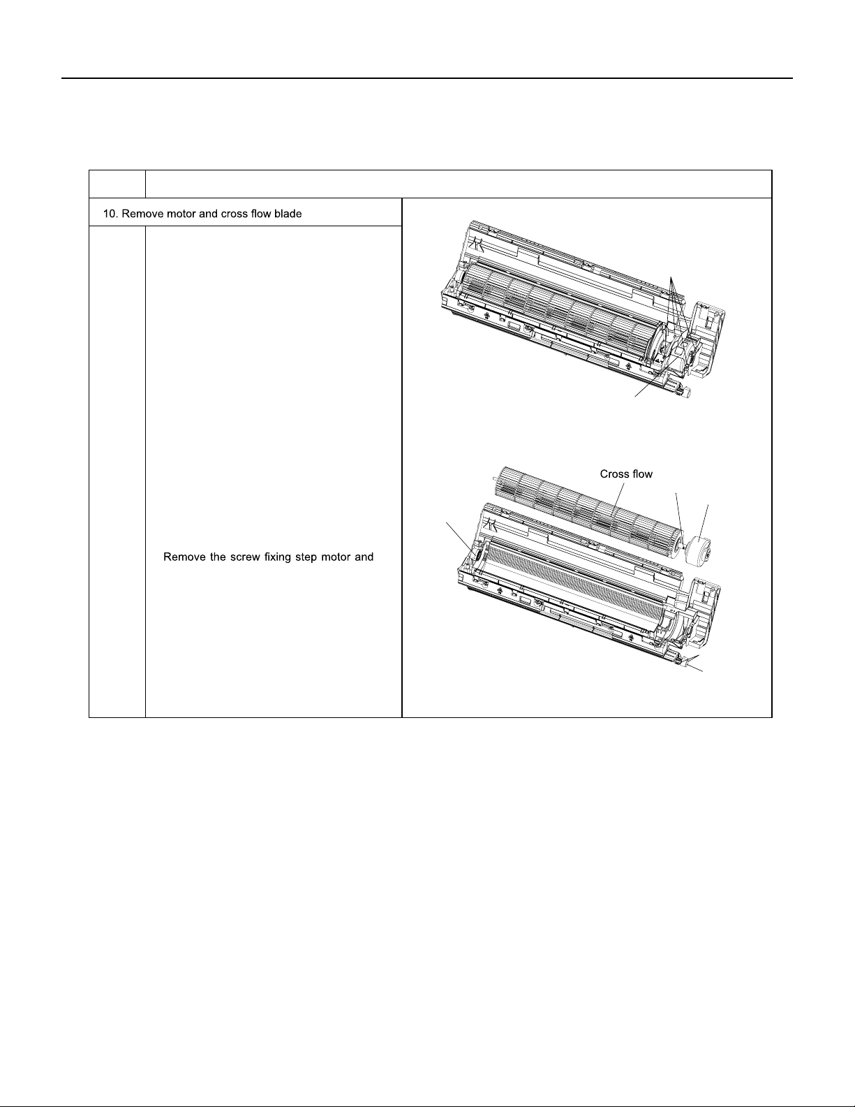
67 PB
REMOVAL
Indoor Unit
ProcedureSteps
Remove the screws fixing motor clamp
and then remove the motor clamp.
Screws
Screw
Motor clamp
Motor
Holder
sub-assy
Step motor
Remove the screws at the connection
place of cross flow blade and motor; lift
the motor and cross flow blade upwards
to remove them.
Remove the bearing holder sub-assy.
then remove the step motor.
Screws
a
b
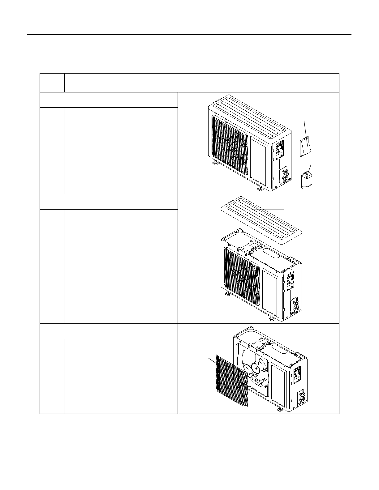
68 PB
REMOVAL
Outdoor Unit
ProcedureSteps
1.Remove cable cross plate sub-assy
and valve cover
3.Remove front grille
2.Remove top cover
Remove the screws fixing cable cross plate
sub-assy and then remove the cable cross plate
sub-assy.
Remove the screws fixing valve cover and then
remove the valve cover.
top cover
cable cross plate
sub-assy
valve cover
front grille
Remove connection screws connecting the
top cover plate with the front panel and the
right side plate,and then remove the top
cover.
Remove connection screws between the
front grille and the front panel. Then remove
the front grille.
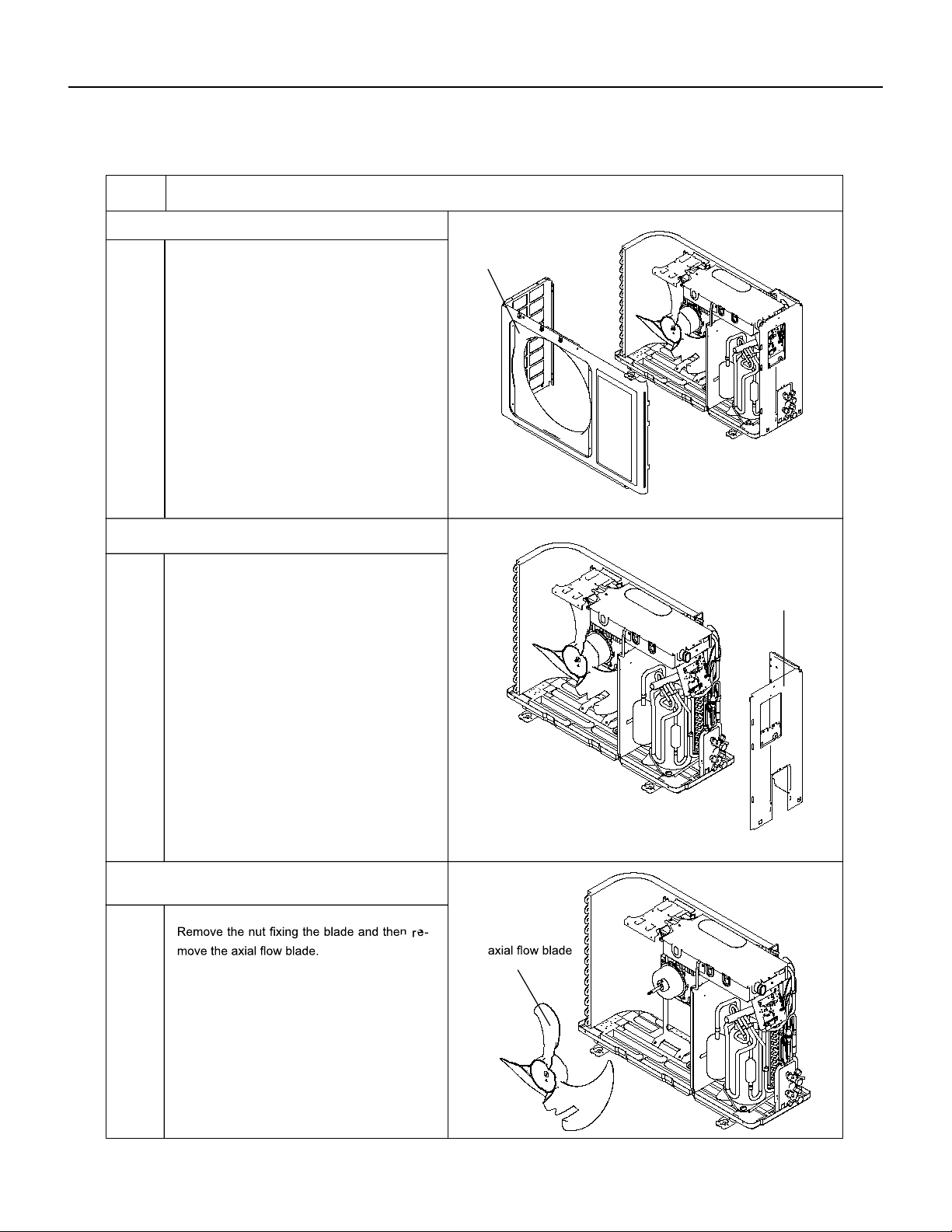
69 PB
REMOVAL
Outdoor Unit
4.Remove front panel
5.Remove right side plate
Procedure
6.Remove axial flow blade
Steps
Remove connection screws connecting the
front panel with the chassis and the motor
support, and then remove the front panel.
front panel
right side plate
Remove connection screws connecting the
right side plate with the valve support and
the electric box. Then remove the right side
plate.
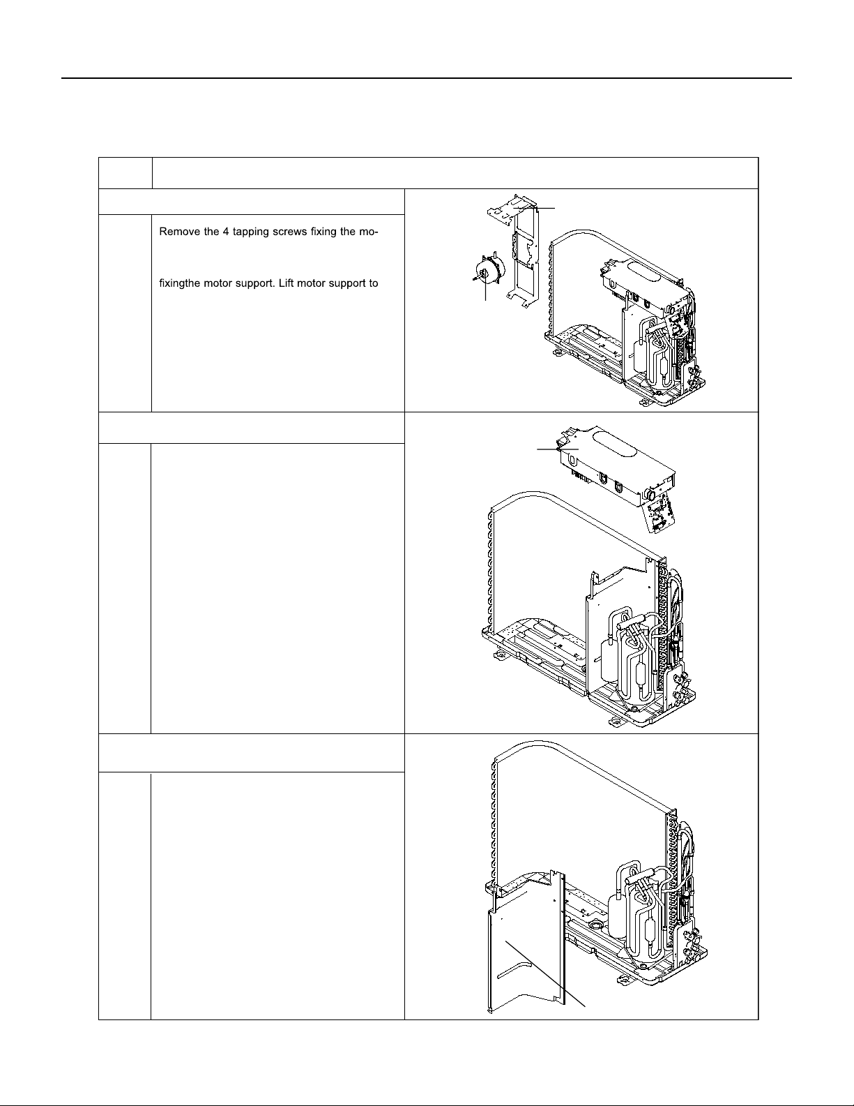
70 PB
REMOVAL
Outdoor Unit
7.Remove motor and motor support
8.Remove electric box assy
Procedure
9.Remove clapboard sub-assy
Steps
tor Pull out the lead-out wire and remove
themotor. Remove the 2 tapping screws
re-move it.
Remove the 2 screws fixing the cover of
elec-tric box. Lift to remove the cover. Loos-
en thewire and disconnect the terminal. Lift
to re-move the electric box assy.
motor support
motor
electric box assy
clapboard sub-assy
Loosen the screws of the clapboard sub-
assy .The clapboard sub-assy has a hook
on thelower side. Lift and pull the clapboard
sub-assy to remove.
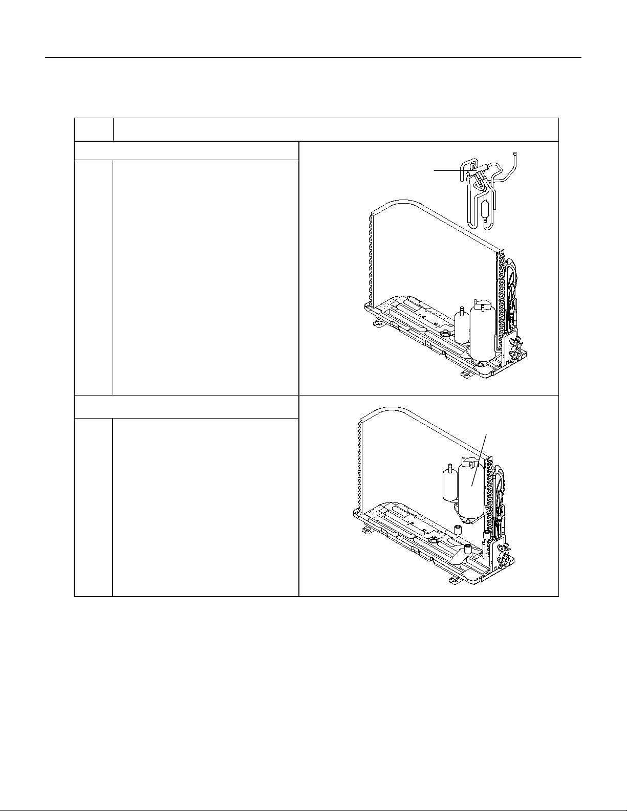
71 PB
REMOVAL
Outdoor Unit
10.Remove 4-way valve assy
ProcedureSteps
11.Remove compressor
4-way valve assy
compressor
Remove the 3 footing screws of the com-
pressorand remove the compressor.
Unscrew the fastening nut of the 4-way
Valve Assy coil and remove the coil. Wrap
the 4-way Valve Assy with wet cotton and
unsolder the 4 weld spots connecting the
4-way Valve Assy to take it out (Note: Refrig-
erant shouldbe discharged firstly.) Welding
process should be as quickly as possible and
keep wrapping cotton wet all the time. Be
sure not to burn out the lead-out wire of com-
pressor.
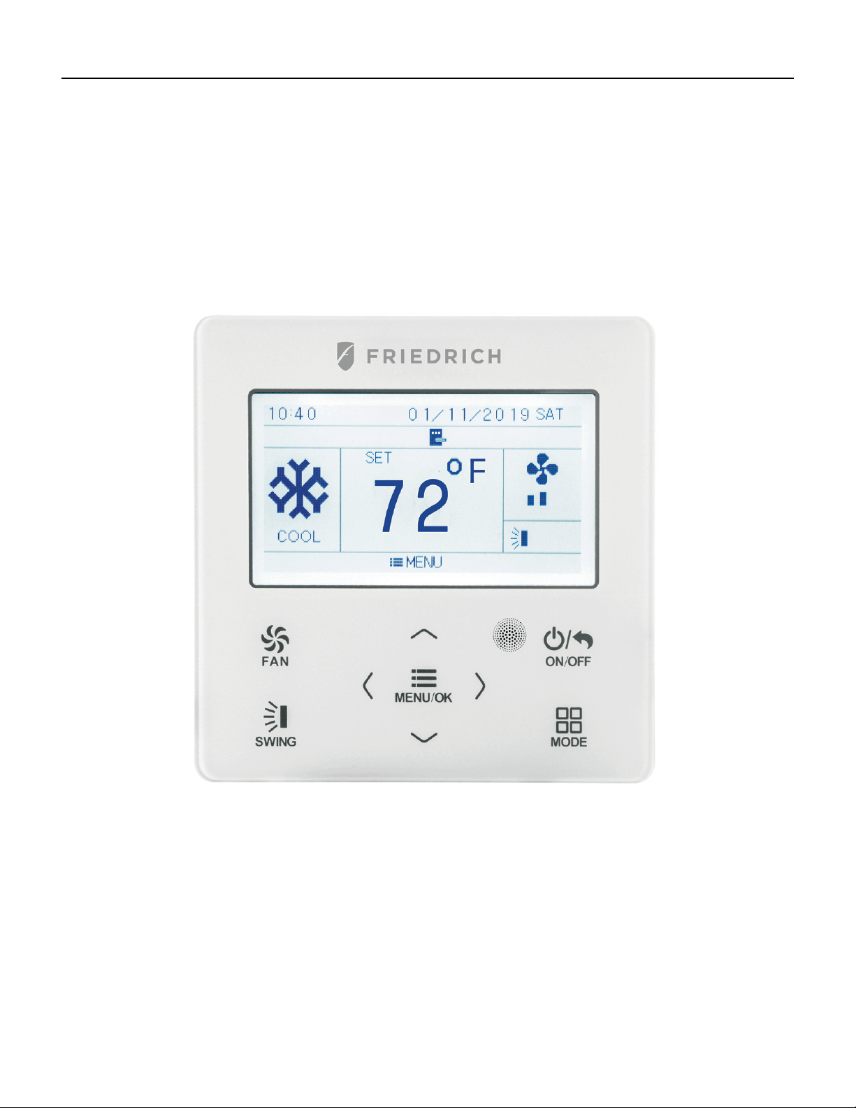
72 PB
WIRED CONTROLLER
Display
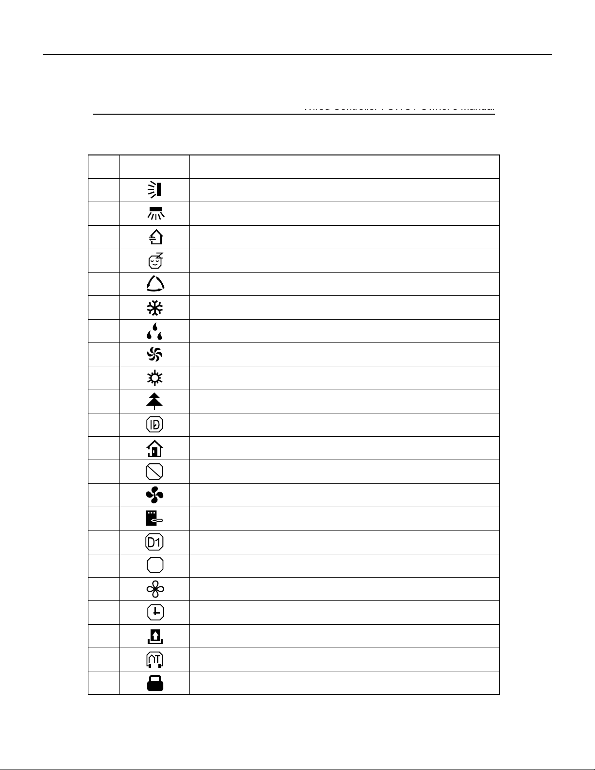
73 PB
Wired Controller FSWC1 Owner's Manual
2
1.2 Instructions for Related Displayed Symbols
No. Symbols Instructions
1 Up and down swing function
2 Left and right swing function
3 Fresh air function
4 Sleep function
5 Auto mode
6 Cooling mode
7 Dry mode
8 Fan mode
9 Heating mode
10 Health function
11 I-Demand function
12 Absence function
13
Shielding status (Buttons, temperature, ON/OFF, mode or energy saving is
shielded by remote monitor)
14 Current set fan speed
15 Memory function (Memory in power failure)
16
Save function
17
X-fan function
18
Timer on status
19
Gate card pulled-off status or nobody presented status
20
Quiet function
21
22 Function lock
DRED function
$
WIRED CONTROLLER
Display
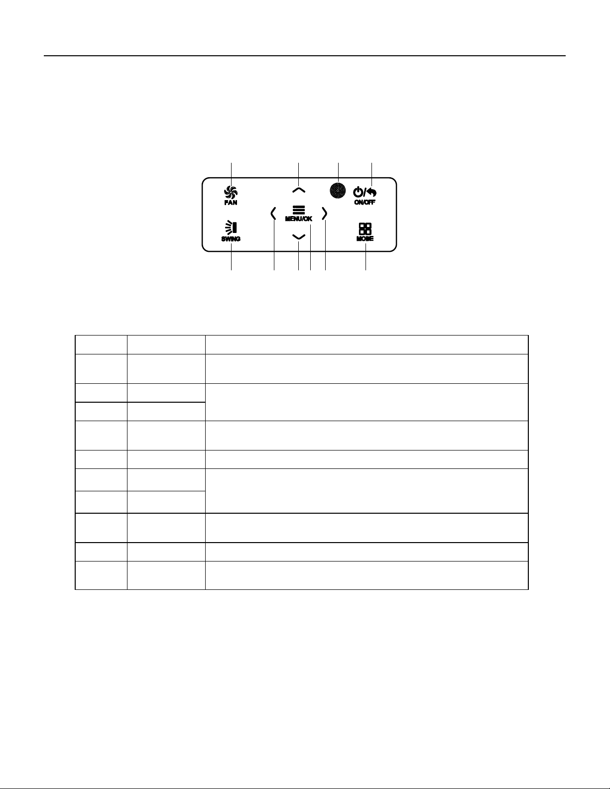
74 PB
Wired Controller FSWC1 Owner's Manual
3
2 Buttons
2.1 Button Graphics
Fig. 2 Button graphics
2.2 Function Instructions of Buttons
No. Button name Button Function
1 FAN
Set low speed, medium speed,high speed, turbo and auto speed.
2
∧
(1) Set temperature
(2) Set parameter
(3) Move option cursor
6
∨
3 ON/OFF/BACK
(1) Turn on or turn off unit
(2) Return to last page
4 SWING Set up&down swing and set left&right swing
5
<
(1) Set related function on or off
(2) Move option cursor
(3) Set parameter
8
>
7 MENU/OK
(1) Enter menu page
(2) Confirm setting
9
10
MODE Set auto, cooling, dry, fan and heating modes for indoor unit.
3 Operation Instructions
3.1 Menu Structure
Normal setting of wired controller can be set directly on the main page, including
fan speed, swing, set temperature, mode, ON/OFF. The setting and status view of
other functions can be set in corresponding submenu. Detailed menu structure is as
shown in Fig. 3.
1 2 3
4 56
10
978
Remote control
receiver window
WIRED CONTROLLER
Buttons
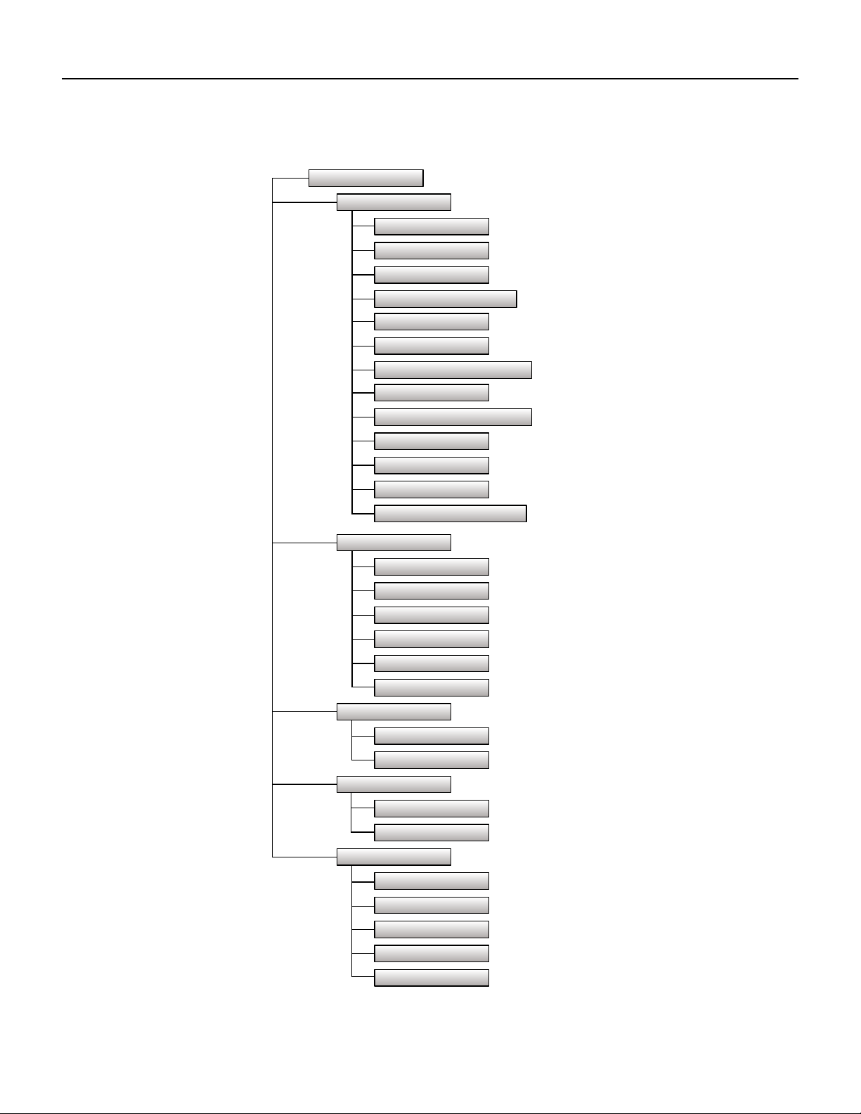
75 PB
Main menu
User function menu
Fresh air function setting
Sleep function setting
Health function setting
Absence function setting
I-DEMAND function setting
Memory function setting
Save function setting
Fixed-angle swing function setting
Auxiliary heat function setting
Dry function setting
Quiet function setting
Fahrenheit Temperature Setting
Air function setting
Timer setting menu
Once
Clock setting menu
Time format setting
Daily
Weekly timer
Two week timer
Countdown timer on
Countdown timer off
Clock setting
View function menu
Unit status view
Current error view
Function lock menu
Unit ON/OFF lock
Mode setting lock
Temperature setting lock
Fan speed setting lock
Key lock
Wired Controller FSWC1 Owner's Manual
4
Fig. 3 Menu structure
WIRED CONTROLLER
Operation Instructions
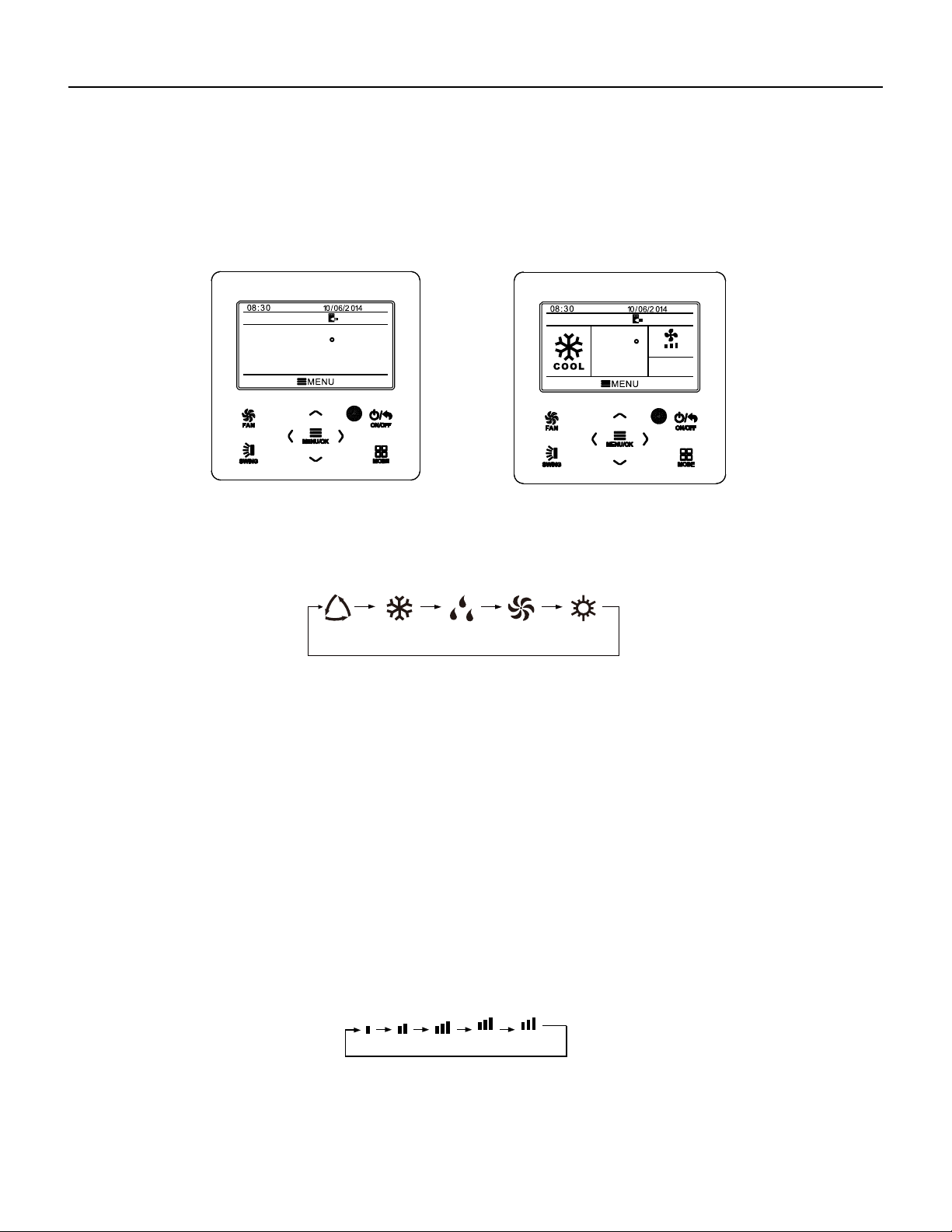
76 PB
Wired Controller FSWC1 Owner's Manual
5
3.2 On/Off
When the wired control is on main page, press ON/OFF button to turn on the unit.
Press ON/OFF button again to turn off the unit. The interfaces of On/Off status are
shown in Fig. 4 and Fig. 5.
Fig. 4 Off interface Fig. 5 On interface
3.3 Mode Setting
Under On status, pressing MODE button can set mode circularly as:
Note: If save function is on, auto mode is not available.
(COOLING)(DRY)(FAN)(HEATING)
3.4 Temperature Setting
Under unit on status, pressing “
∧
” or “
∨
” button on the main page increases or
decreases set temperature by 1℃(1℉); holding “
∧
” or “
∨
” button increases or
decreases set temperature by 1℃(1℉) every 0.3s.
In cooling,dry,fan and heating mode,temperature setting range is 16℃~30℃
(61℉~86℉). Under auto mode, set temperature cannot be adjusted.
(AUTO)
3.5 Fan Setting
Under On status, pressing FAN button can set fan speed circularly as:
Low→Medium→High→Turbo→Auto→Low
Symbols displayed are as shown in Fig. 6.
Fig. 6 Fan
setting
TURBO AUTO
MON
SET
MON
SET
AUTO
26
C
26
C
WIRED CONTROLLER
Operation Instructions
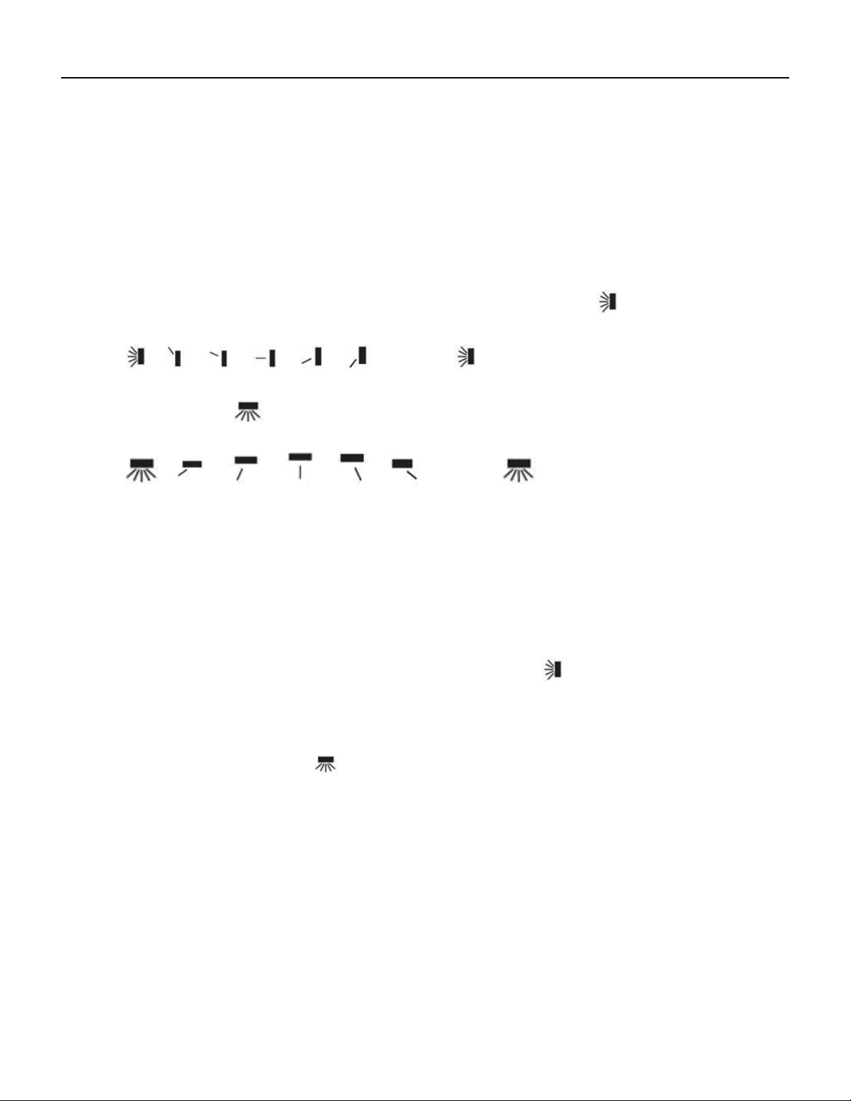
77 PB
Wired Controller FSWC1 Owner's Manual
6
3.6 Swing Setting
In unit on status, press SWING button for swing setting. Two swing modes are
available: fixed-angle swing and simple swing.
When fixed-angle swing mode is set, swing operation is as follows:
In unit on status, press SWING button to select up&down swing
. Up&down
swing angle will be adjusted circularly as below:
→ → → → → → closed →
Select up&down swing and left&right swing through “
<
” or “
>
” button. When
left&right swing
is selected. Left&right swing angle will be adjusted circularly as
below:
→ → → → → → closed→
Note:
①
.
Turn on fixed-angle swing mode in function setting page;
②
.
If fixed-angle swing is not available for the model, fixed-angle swing will be
invalid when the wired controller turns on fixed-angle swing mode.
Simple swing mode: when fixed-angle swing mode is turned off, swing operation is
as below:
Pressing SWING button under unit on status, up&down swing frame occurs. Then
press SWING button to turn on or turn off up&down swing.
is displayed when
up&down swing is on and is not displayed when up&down swing is off. When up&down
swing frame have not disappeared, press “
<
” or “
>
” button to switch to left&right swing
setting. Then left&right swing frame occurs. In this case, press SWING button to turn on
or turn off left&right swing.
is displayed when left&right swing is on and is not
displayed when left&right swing is off. For detailed operation, please refer to Fig. 7.
WIRED CONTROLLER
Operation Instructions
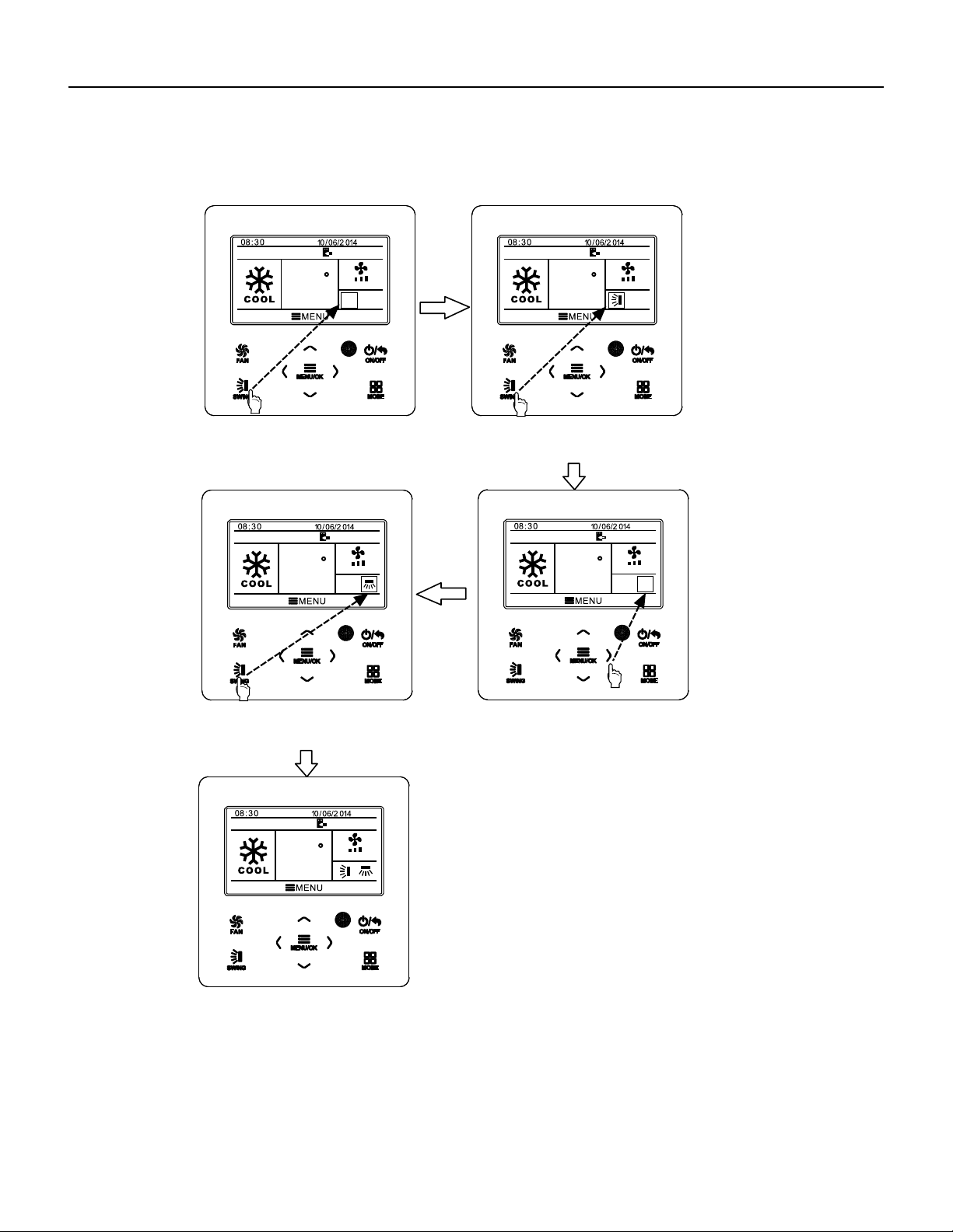
78 PB
Fig. 7 Swing setting
Wired Controller FSWC1 Owner's Manual
7
MON
SET
AUTO
MON
SET
AUTO
MON
SET
AUTO
MON
SET
AUTO
MON
SET
AUTO
Press SWING button to enter swing
setting status.
Press SWING button to turn on or
turn off simple up&down swing
and fixed-angle up&down swing.
Press SWING button to turn on or
turn off simple left&right swing
and fixed-angle left&right swing.
Press “<”or “>” button to switch
between up&down swing and
left&right swing setting.
After finishing setting, setting status
will be exited automatically after 5s.
26
C
26
C
26
C
26
C
26
C
WIRED CONTROLLER
Operation Instructions
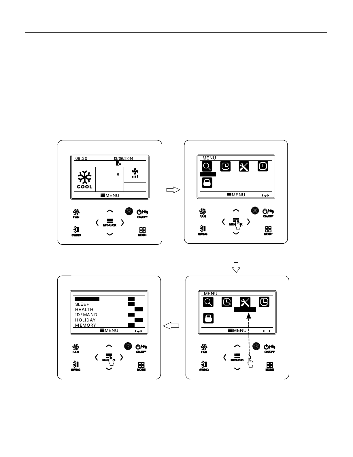
79 PB
Wired Controller FSWC1 Owner's Manual
Fig. 8 Function setting
3.7 Functions Setting
Press MENU/OK button on main page to enter main menu page. Press “
∧
” or “
∨
”
or “
<
” or “
>
” button to select the function setting symbol. Then press MENU/OK button
to enter user function setting page. Press “
∧
” or “
∨
” button to select specific function
item. Press “
<
” or “
>
” button to turn on or turn off this function. If the function item
cann’t be set, it will displays with gray color. Please refer to Fig.8.
MON
SET
AUTO
SEARCH
TIMER
FUNCTION
CLOCK
LOCK
FUNCTION
FRESH AIR
ON
OFF
ON
OFF
ON
OFF
ON
OFF
ON
OFF
ON
OFF
SEARCH
TIMER
FUNCTION
CLOCK
LOCK
IN main page.
Press MENU/OK button to enter main menu page.
Press “>” button to select function setting item.
Press MENU/OK button to enter function setting page;
press “
∧” or “∨” to select function item, and press “< ” or
“>” button to set the function.
26
C
8
WIRED CONTROLLER
Operation Instructions

80 PB
Wired Controller FSWC1 Owner's Manual
9
3.7.1 Fresh Air Function Setting
After entering user function page, press “ ” or “ ” button to select fresh air
function and press “
” or “ ” button to turn on or turn off air function. Press MENU
button to adjust the mode of fresh air.
After entering fresh air mode setting, press “ ” or “ ” button to adjust the mode in
the range of 1~10. After setting, press MENU button to save the setting.
3.7.2 Sleep Function Setting
After entering user function page, press “∧” or “∨” button to select sleep function
and press “<” or “>” button to turn on or turn off sleep function with auto saving.
If this function is turned on, the unit will operate according to the preset sleep curve
to provide comfortable sleep environment.
Note:
●In fan or auto mode, sleep function is not available.
●Sleep function will be cancelled when turning off the unit or switching modes.
WIRED CONTROLLER
Operation Instructions

81 PB
If fixed-angle swing function is not available for the connected unit, this
function will be cancelled automatically after setting.
This function is only available in cooling mode.
When this function has been set, set temperature is displayed in SE.
In this case, temperature setting and fan speed setting are shielded.
This function and sleep function cannot be on simultaneously. If I-demand
function is set firstly and then sleep function is set, I-demand function will be
cancelled while sleep function will be valid, and vice versa.
3.7.5 Absence Function Setting
Note:
Note:
Note:
3.7.3 Health Function Setting
After entering user function page, press “
∧
” or “
∨
” button to select health function
and press “
<
” or “
>
” button to turn on or turn off health function with auto saving.
●This function is only available in heating mode.
●When this function has been set, set temperature is displayed in 8℃(46℉). In this
case, temperature setting and fan speed setting are shielded.
●This function will be cancelled when switching modes.
●
●
●
●
●
This function and sleep function cannot be on simultaneously. If absence function
is set firstly and then sleep function is set, absence function will be cancelled while
sleep function will be valid, and vice versa.
3.7.6 Memory Function Setting
After entering user function page, press “
∧
” or “
∨
” button to select memory
function and press “
<
” or “
>
” button to turn on or turn off memory function with auto
saving.
3.7.7 Fixed-angle Swing Mode Setting
After entering user function page, press “∧” or “∨” button to select holiday function
option and press “<” or “>” button to turn on or turn off this function with auto saving.
This function is used to maintain indoor temperature so that unit can realize fast
heating.
After entering user function page, press “
∧
” or “
∨
” button to select IDEMAND
function option and press “
<
” or “
>
” button to turn on or turn off this function with auto
saving.
After entering user function page, press “
∧
” or “
∨
” button to select lock swing
function option and press “
<
” or “
>
” button to turn on or turn off this function with auto
saving.
3.7.4 I-DEMAND Function Setting
Wired Controller FSWC1 Owner's Manual
10
This function will be cancelled when switching modes.
WIRED CONTROLLER
Operation Instructions

82 PB
temperature, press “
∧
” or “
∨
” button to adjust limitation temperature value. After
setting, press MENU button to save the setting.
Note: When save function has been set, auto mode cannot be set.
3.7.8 Save Function Setting
After entering user function page, press “
∧
” or “
∨
” button to select save function
and press “
<
” or “
>
” button to turn on or turn off save function. Press MENU button to
enter save function setting page.
After entering save function setting page, press “
<
” or “
>
” button to select cooling
or heating limitation temperature. After selecting cooling or heating limitation
3.7.9 Auxiliary Heating Function Setting
After entering user function page, press “
∧
” or “
∨
” button to select auxiliary
heating function and press “
<
” or “
>
” button to turn on or turn off this function with auto
saving.
3.7.10 X-fan Function Setting
After entering user function page, press “
∧
” or “
∨
” button to select dry function
option and press “
<
” or “
>
” button to turn on or turn off this function with auto saving.
Note:
This function is only available in cooling mode and dry mode.
3.7.11 Quiet Function Setting
After entering user function page, press “
∧
” or “
∨
” button to select quiet function
and press “
<
” or “
>
” button to turn on or turn off this function with auto saving.
Note: This function is only available in cooling mode, heating mode and auto
mode.
3.7.12 Fahrenheit Temperature Setting
After entering user function page, press “∧” or “∨” button to select Fahrenheit
temperature function and press “<” or “>” button to turn on or turn off this function
with auto saving. After closing this function, Celsius temperature will be displayed.
●
Wired Controller FSWC1 Owner's Manual
11
WIRED CONTROLLER
Operation Instructions
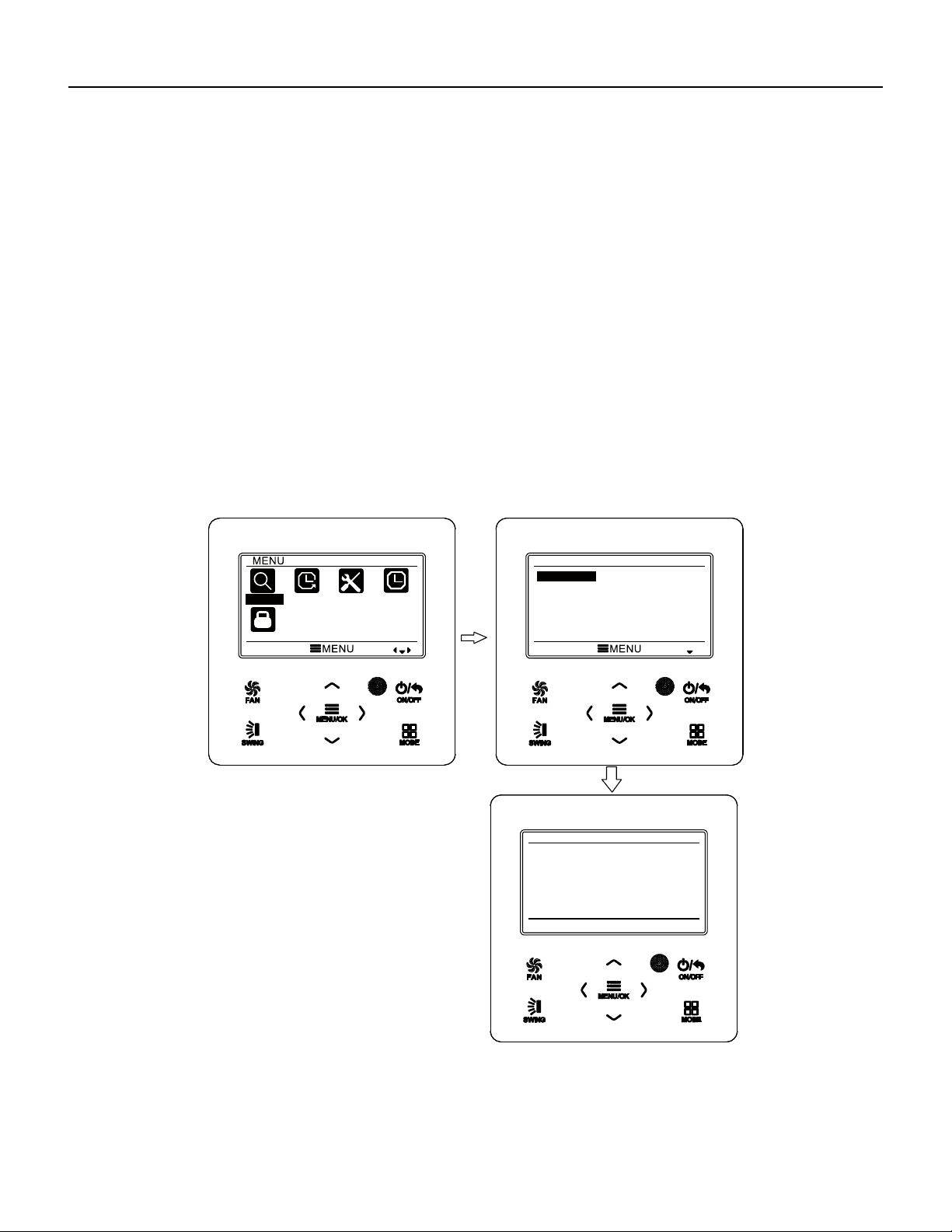
83 PB
After entering user function page, press “∧” or “∨” button to select Air Function
and press “<” or “>” button to turn on or turn off air function. Press MENU button to
adjust the mode of Air Function .
After entering Air Function mode setting, press “∧” or “∨” button to adjust the
mode in the range of 1~2. After setting, press MENU button to save the setting.
3.7.13 Air Function Setting
The each mode means as follows:1- suction 2-discharge
3.8 Unit Status View
Press MENU button to enter the menu and select the function symbol to be viewed.
Then press MENU button to enter view function page. Press “∧” or “
∨
” button to select
status view function. Press MENU button to enter unit status view page. Press BACK
button to return to the last page. Please refer to Fig. 9.
The following statuses can be viewed: if auxiliary heating is operating;indoor ambient
temperature; outdoor ambient temperature.
Wired Controller FSWC1 Owner's Manual
12
Fig. 9 Status View
SEARCH
TIMER
FUNCTION
CLOCK
LOCK
SEARCH
UNIT STATUS
ERROR INFORMATION
UNIT STATUS
INDOOR TEMPERATURE
OUTDOOR TEMPERATURE
RETURN
19℃
19℃
WIRED CONTROLLER
Operation Instructions
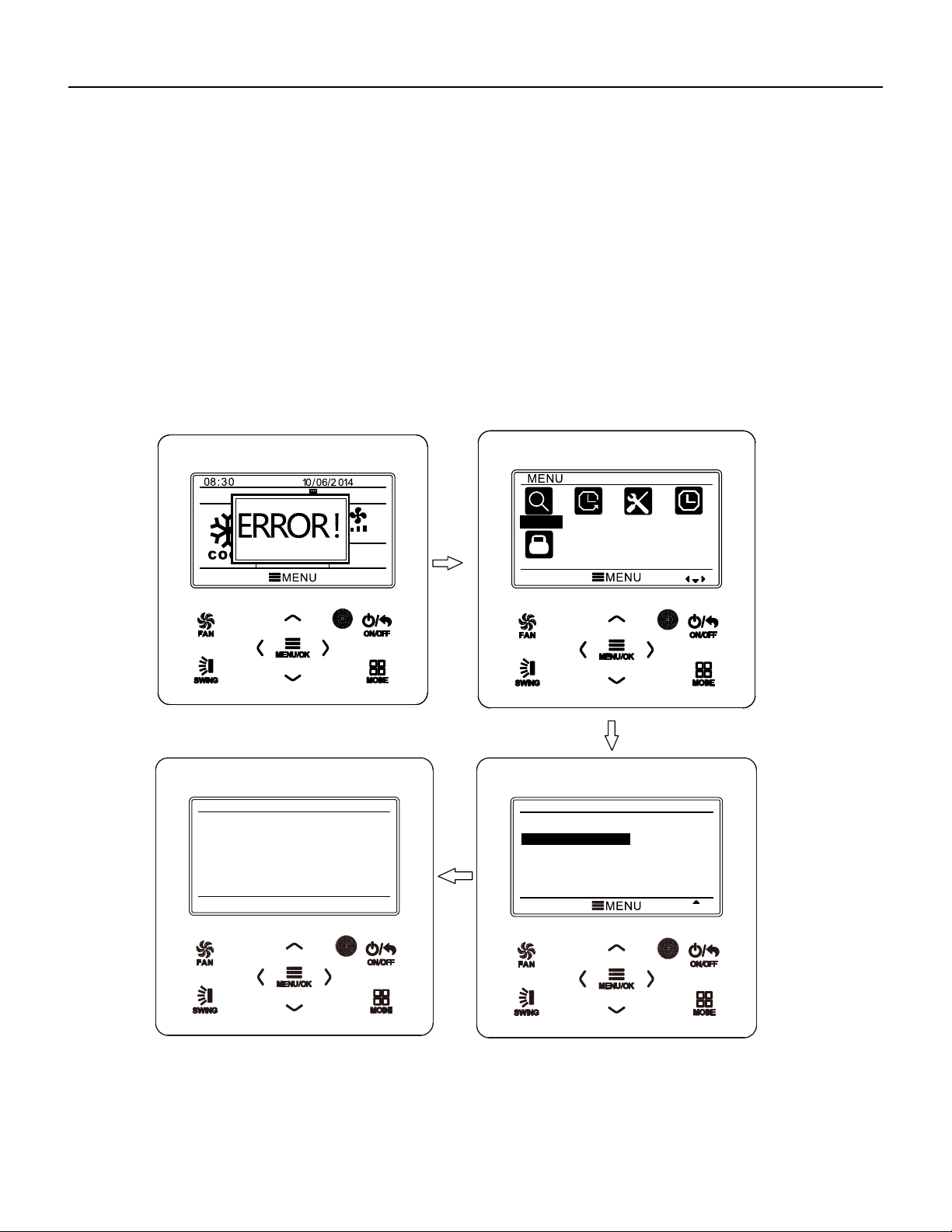
84 PB
3.9 Current Error View
When error occurs in the unit, error symbol will be displayed on the main page of
wired controller to indicate that the unit is with error. In this case, you can enter error
view page to view the current error.
Press MENU button to enter the menu and select the function symbol to be viewed.
Then press MENU button to enter view function page. Press “
∧
” or “
∨
” button to select
error information. Press MENU button to enter err
or view page. If there are too many
errors, press “
∧
” or “
∨
” to turn pages. Press BACK button to return to the last page.
Please refer to Fig. 10.
Fig. 10 Current Error View
Wired Controller FSWC1 Owner's Manual
13
MON
SET
AUTO
AM
SEARCH
TIMER
FUNCTION
CLOCK
LOCK
SEARCH
UNIT STATUS
ERROR INFORMATION
ERROR INFORMATION
E6
RETURN
WIRED CONTROLLER
Operation Instructions
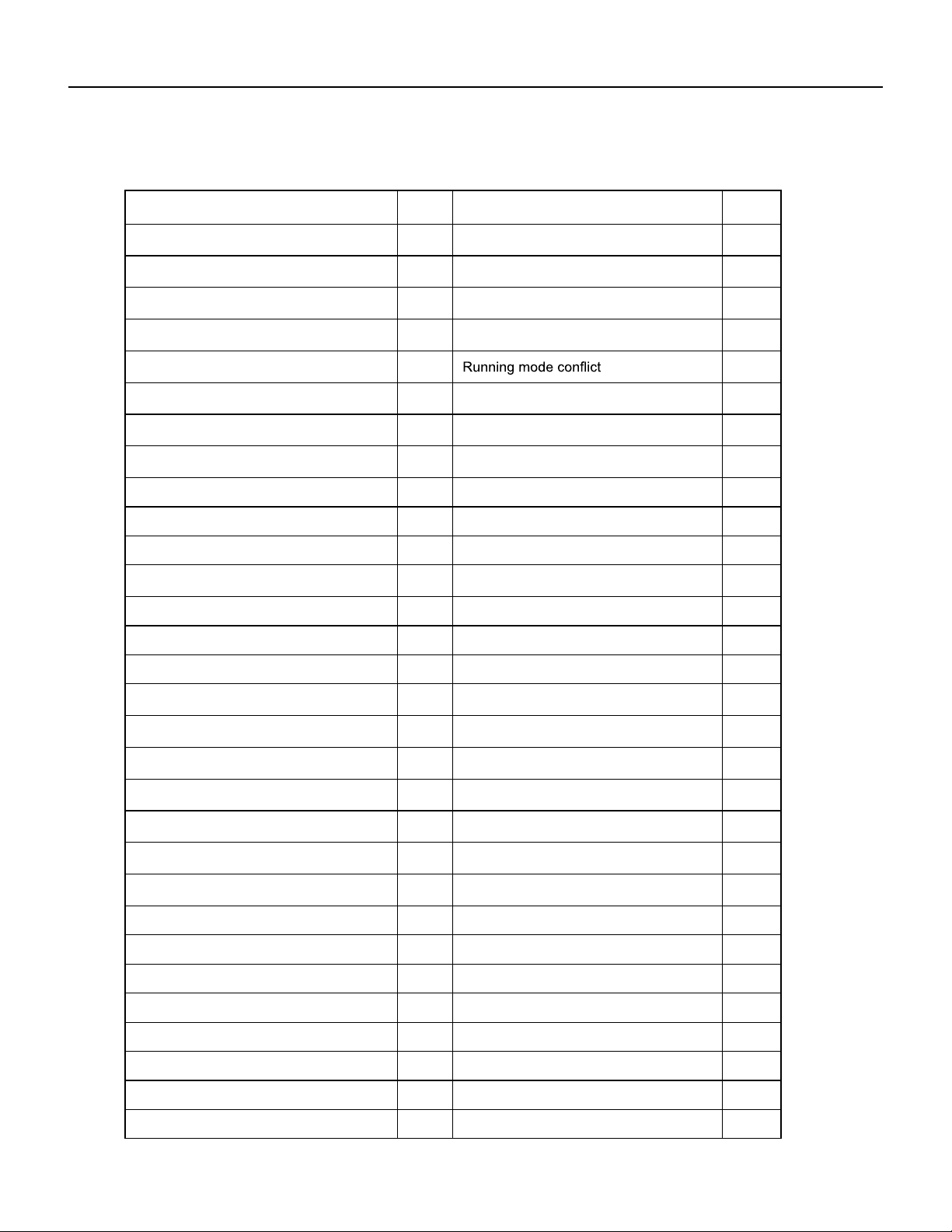
85 PB
U0Indoor fan tripping error
dc
compressor inhalation temperature
sensor error
14
Wired Controller FSWC1 Owner's Manual
Error
Error
Code
Error
Error
Code
Return air temperature sensor open/
short circuited
F1 Drive board communication error P6
evaporator temperature sensor open/
short circuited
F2 Compressor overheating protection H3
Indoor unit liquid valve temperature
sensor open/short circuited
b5 Indoor and outdoor units unmatched LP
Indoor gas valve temperature sensor
open/ short circuited
b7
Communication line misconnected or
expansion valve error
dn
IPM temperature sensor open/short
circuited
P7
E7
Outdoor ambient temperature sensor
open/ short circuited
F3 Pump-down Fo
Outdoor unit condenser mid-tube
temperature sensor open/short circuited
F4 Jumper error C5
Discharge temperature sensor open/
short circuited
F5 Forced defrosting H1
Indoor and outdoor communication error E6 Compressor startup failure Lc
DC bus under-voltage protection PL High discharge temperature protection E4
DC bus over-voltage protection PH Overload protection E8
Compressor phase current sensing
circuit error
U1 Whole unit over-current protection E5
Compressor demagnetization protection HE Over phase current protection P5
PFC protection Hc Compressor desynchronizing H7
IPM Temperature Protection P8 IPM Current protection H5
Over-power protection L9
Compressor phase loss/reversal
protection
Ld
System charge shortage or blockage
protection
F0
Frequency restricted/reduced with whole
unit current protection
F8
Capacitor charging error PU
Frequency restricted/reduced with IPM
current protection
En
High pressure protection E1
Frequency restricted/reduced with high
discharge temperature
F9
Low pressure protection E3
Frequency restricted/reduced with anti-
freezing protection
FH
Compressor stalling LE
Frequency restricted/reduced with
overload protection
F6
Over-speeding LF
Frequency restricted/reduced with IPM
temperature protection
EU
Drive board temperature sensor error PF Indoor unit full water error E9
AC contactor protection P9 Anti-freezing protection E2
Temperature drift protection PE AC input voltage abnormal PP
Sensor connection protection Pd Whole unit current sensing circuit error U5
DC bus voltage drop error U3 4-way valve reversing error U7
Outdoor fan 1 error protection L3 Motor stalling H6
Outdoor fan 2 error protection LA PG motor zero-crossing protection U8
WIRED CONTROLLER
Operation Instructions
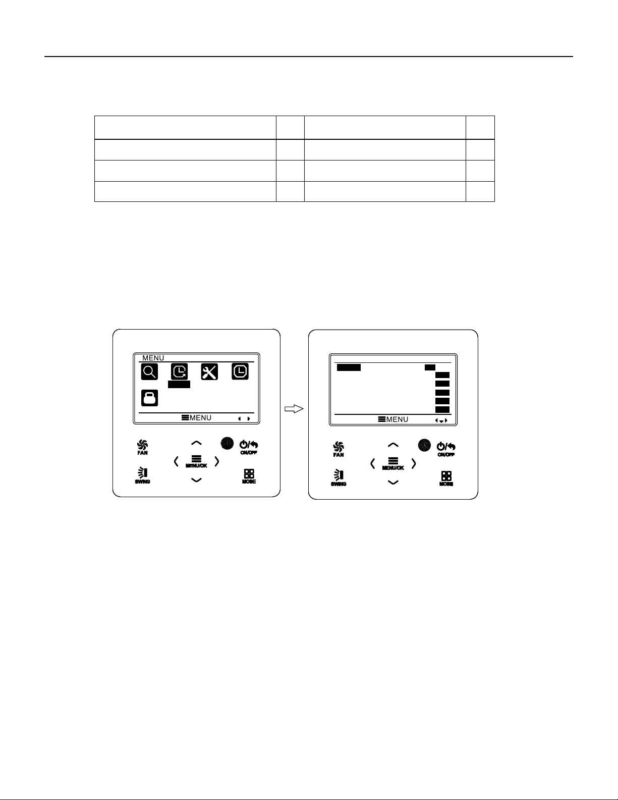
86 PB
Error
Error
Code
Error
Error
Code
Communication error between IDU and
grid connection
Communication error between ODU and
grid connection
Main error at grid connection side
IDU network address error
Ip address allocation overflow
Ln
LM
y2
y3
yb
3.10 Timer Setting
The wired controller can set 6 kinds of timer: one time clock timer, everyday timer,
one week timer, two week timer, countdown timer on and countdown timer off. Select
timer symbol after entering menu page. Press MENU button to enter timer setting page.
Press “
∧
” or “
∨
” button to select one kind of timer. Press “
<
” or “
>
” button to turn on
or turn off this timer. Please refer to Fig. 11.
Fig. 11 Turn on or turn off timer
3.10.1 One Time Clock Timer
The wired controller can set one time clock timer. If the unit is off, timer on can be
set. If the unit is on, timer off can be set. This timer will be carried out for only once
when timer time is reached and then the timer will be off automatically.
In timer function setting page, when one time timer is selected, press “
<
” or “
>
”
button to turn on or turn off this timer function.
Press MENU button to enter timer time
setting page, as shown in Fig. 12.
Press “
<
” or “
>
” button to select timer hour or minute and press “
∧
” or “
∨
” button
to adjust time. Holding “
∧
” or “
∨
” button increases or decreases time rapidly. After
finishing setting, press MENU button to save timer time.
Wired Controller FSWC1 Owner's Manual
15
SEARCH
TIMER
FUNCTION
CLOCK
LOCK
TIMER
ONCE
ON
OFF
ON
OFF
ON
OFF
DAILY
WEEKLY
TWO WEEK
TIMER ON
TIMER OFF
ON
OFF
ON
OFF
ON
OFF
WIRED CONTROLLER
Operation Instructions
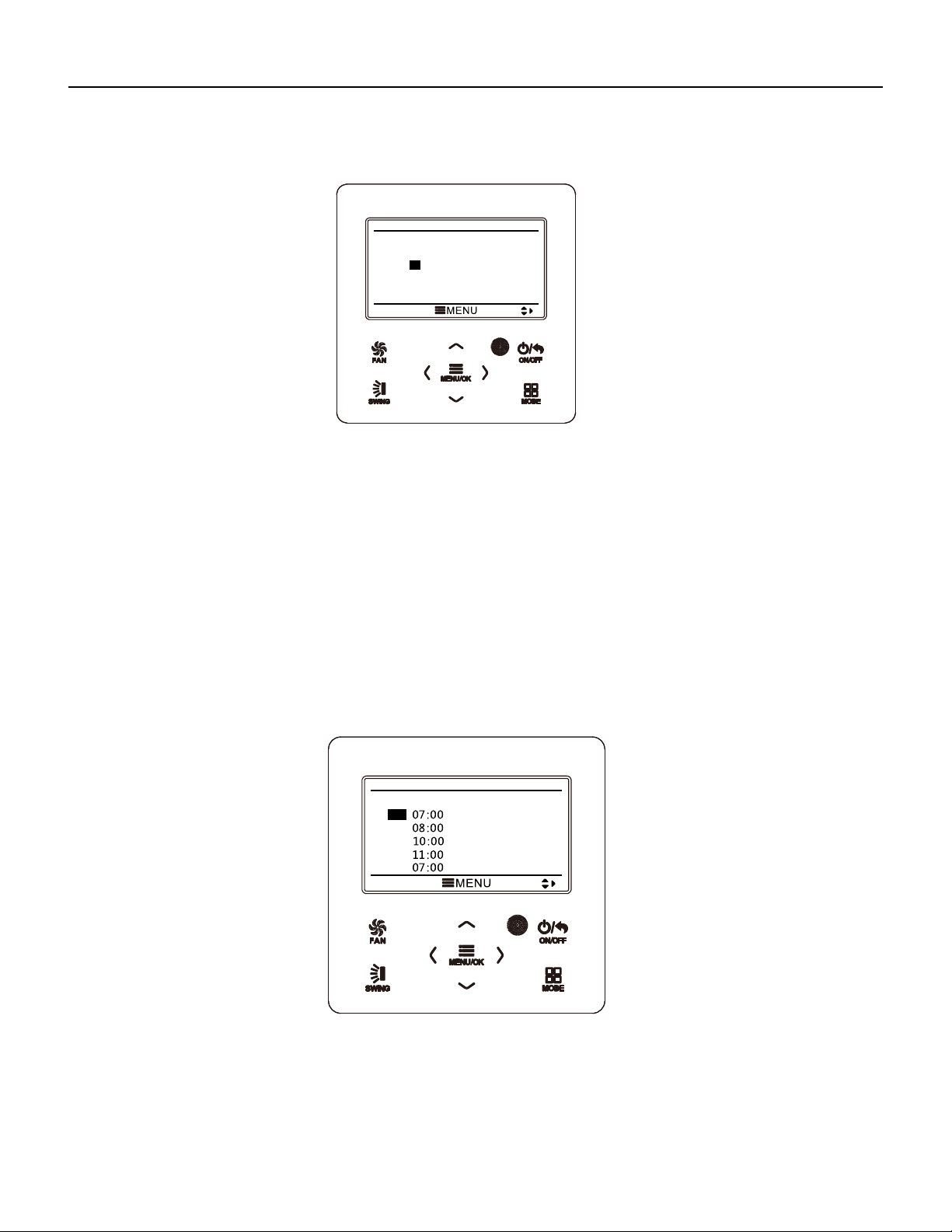
87 PB
Fig. 12 Setting page of one time clock timer
Note: If this timer function is turned on, when the unit is turned on or turned off, this
timer function will be cancelled automatically.
3.10.2 Daily Timer
In daily timer, user can set eight segments of timer individually. The individual
segment will be valid only when it is turned on. In each segment, you can set time, unit
ON/OFF, set temperature in cooling (it is valid only when the current mode is cooling),
set temperature in heating (it is valid only when the current mode is heating).
Please refer to Fig. 13 to select setting.
After entering daily timer setting page, press “
<
” or “
>
” button
item. Press “
∧
” or “
∨
” button to adjust the value. Press MENU button to save setting.
Fig. 13 Daily timer setting
3.10.3 Weekly Timer
The user can set the everyday timer content for a week. In each day, the user can
set eight segments of timer content. The unit will execute corresponding timer setting in
a week.
Wired Controller FSWC1 Owner's Manual
16
ONCE
12:46 ON
DAILY
SCH TIME OnOFF COOL HEAT
1
2
3
4
5
ON
ON
ON
ON
OFF
ON
OFF
ON
ON
OFF
26℃
26℃
26℃
26℃
26℃
26℃
26℃
26℃
26℃
26℃
WIRED CONTROLLER
Operation Instructions
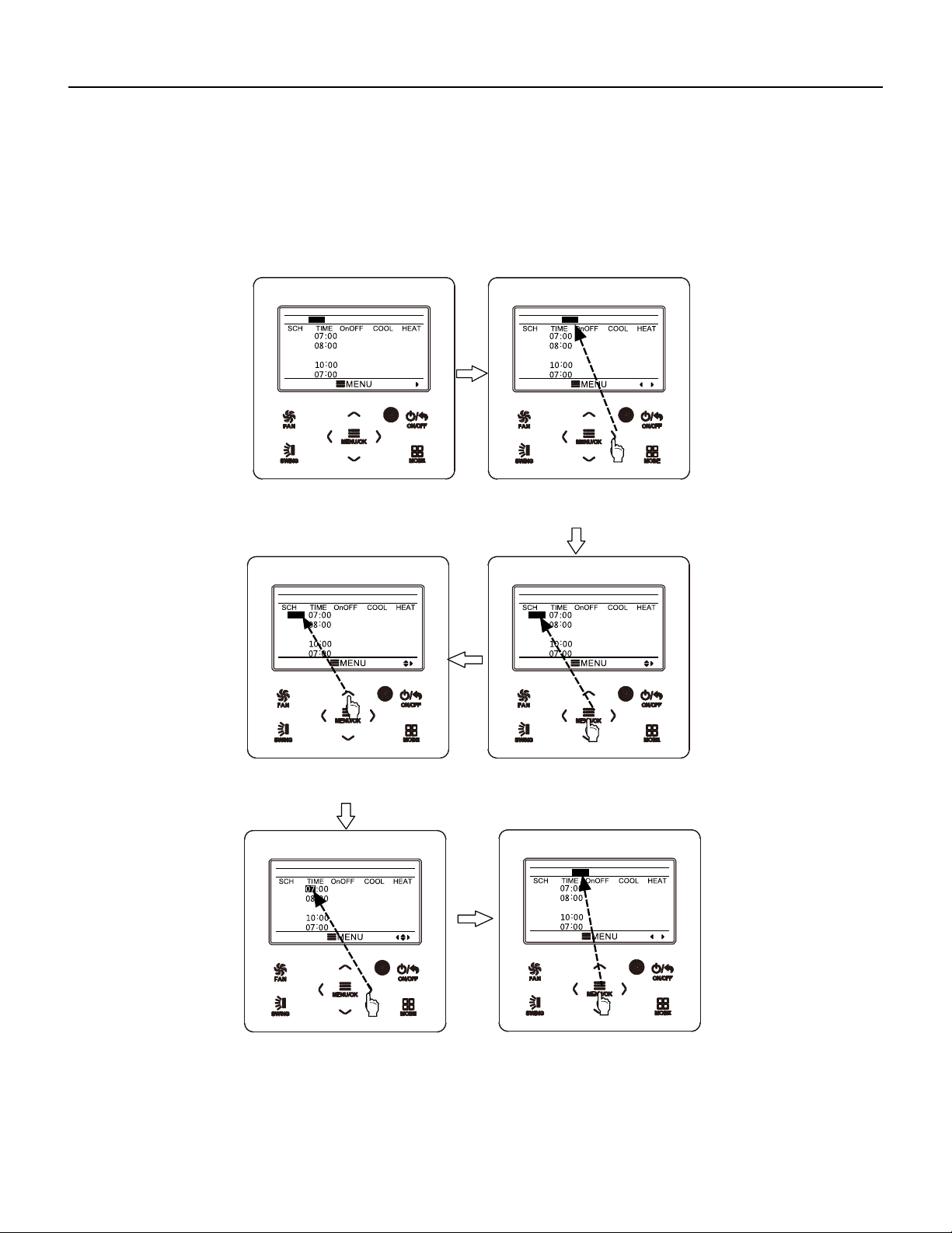
88 PB
After entering weekly timer setting page, press “
<
” or “
>
” button to select the day
to be set. Then press MENU button to enter timer programming of that day. Press “
<
”
or “
>
” button to select the item to be set. Press “
∧
” or “
∨
” button to adjust the content.
Press MENU button to save setting. Please refer to Fig. 14.
Wired Controller FSWC1 Owner's Manual
17
Fig. 14 Weekly timer setting
WEEKLY SCHEDULE
1
2
3
4
5
OFF
ON
ON
ON
OFF
ON
ON
ON
ON
OFF
26℃
26℃
26℃
26℃
26℃
26℃
26℃
26℃
26℃
26℃
WEEK SUN MON TUE WED THU FRI SAT
09:00
WEEKLY SCHEDULE
1
2
3
4
5
OFF
ON
ON
ON
OFF
ON
ON
ON
ON
OFF
26℃
26℃
26℃
26℃
26℃
26℃
26℃
26℃
26℃
26℃
WEEK SUN MON TUE WED THU FRI SAT
09:00
WEEKLY SCHEDULE
1
2
3
4
5
OFF
ON
ON
ON
OFF
ON
ON
ON
ON
OFF
26℃
26℃
26℃
26℃
26℃
26℃
26℃
26℃
26℃
26℃
WEEK SUN MON TUE WED THU FRI SAT
09:00
WEEKLY SCHEDULE
1
2
3
4
5
ON
ON
ON
ON
OFF
ON
ON
ON
ON
OFF
26℃
26℃
26℃
26℃
26℃
26℃
26℃
26℃
26℃
26℃
WEEK SUN MON TUE WED THU FRI SAT
09:00
WEEKLY SCHEDULE
1
2
3
4
5
ON
ON
ON
ON
OFF
ON
ON
ON
ON
OFF
26℃
26℃
26℃
26℃
26℃
26℃
26℃
26℃
26℃
26℃
WEEK SUN MON TUE WED THU FRI SAT
09:00
WEEKLY SCHEDULE
1
2
3
4
5
OFF
ON
ON
ON
OFF
ON
ON
ON
ON
OFF
26℃
26℃
26℃
26℃
26℃
26℃
26℃
26℃
26℃
26℃
WEEK SUN MON TUE WED THU FRI SAT
09:00
Enter weekly timer schedule
setting page.
Press “<” or “>” button to
select the day to beset.
Press “
∧” or “∨” button to
adjust the content.
Press MENU/OK button to
enter timer programming of
that day.
Press “<” or “>” button to
select the item to be set.
After finshing setting, press
MENU/OK button to save
timer setting. Then the cursor
will turn back to day selection.
WIRED CONTROLLER
Operation Instructions
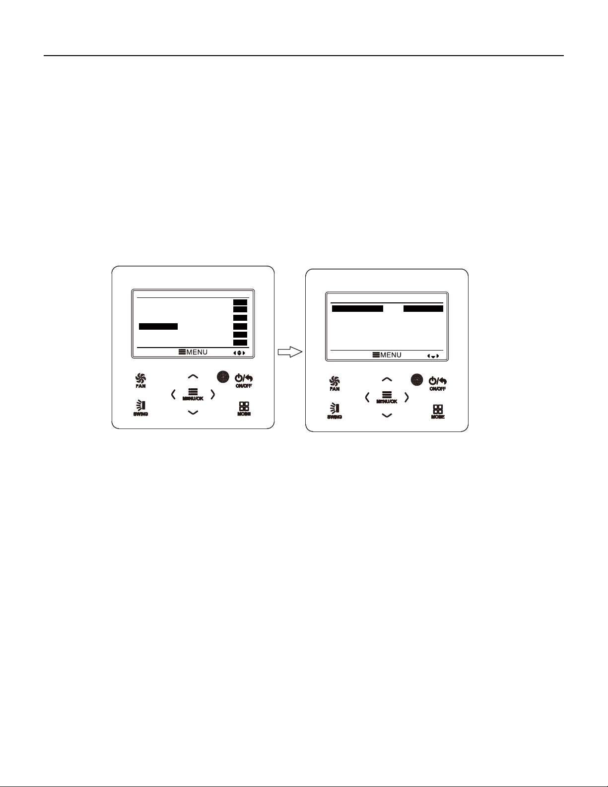
89 PB
Wired Controller FSWC1 Owner's Manual
18
3.10.4 Two Week Timer
The user can set the everyday timer content for two weeks. In each day, the user
can set eight segments of timer content. The unit will execute corresponding timer
setting in two weeks.
In timer function setting page, press “
∧
” or “
∨
” button to select two week timer
setting and then press MENU button to enter two week timer menu page. Press “
∧
” or
“
∨
” button to select current week option and then press “
<
” or “
>
” button to set current
week as first week or second week. Press MENU button to save current week setting.
Please refer to Fig. 15.
Fig. 15 Setting of current week
After entering two week timer menu page, press “
∧
” or “
∨
” button to select the two
week schedule option and then press MENU button to enter two week timer
programming. After entering two week timer setting page, press “
<
” or “
>
” button to
select the day to be set. Then press MENU button to enter timer programming of that
day. Press “
<
” or “
>
” button to select the item to be set. Press “
∧
” or “
∨
” button to
adjust the content. Press MENU button
to save setting. Press BACK button to exit this
page. The setting symbols please refer to weekly timer setting.
3.10.5 Countdown Timer
Countdown timer includes timer on and timer off. Unit On/Off after a desired hour
can be set. In unit on status, timer off can be set, or timer off and timer on can be set
simultaneously. In unit off status, timer on can be set, or timer off and timer on can be
set simultaneously. If timer off in x hours and timer on in y hours are set simultaneously
in unit on status, the unit will be off in x hours and then the unit will be on in y hours after
timer off.
TIMER
ONCE
ON
OFF
ON
OFF
ON
OFF
DAILY
WEEKLY
TWO WEEK
TIMER ON
TIMER OFF
ON
OFF
ON
OFF
ON
OFF
TWO WEEK TIMER MENU
CURRENT WEEK
TWO WEEK SCHEDULE
FIRST WEEK
WIRED CONTROLLER
Operation Instructions
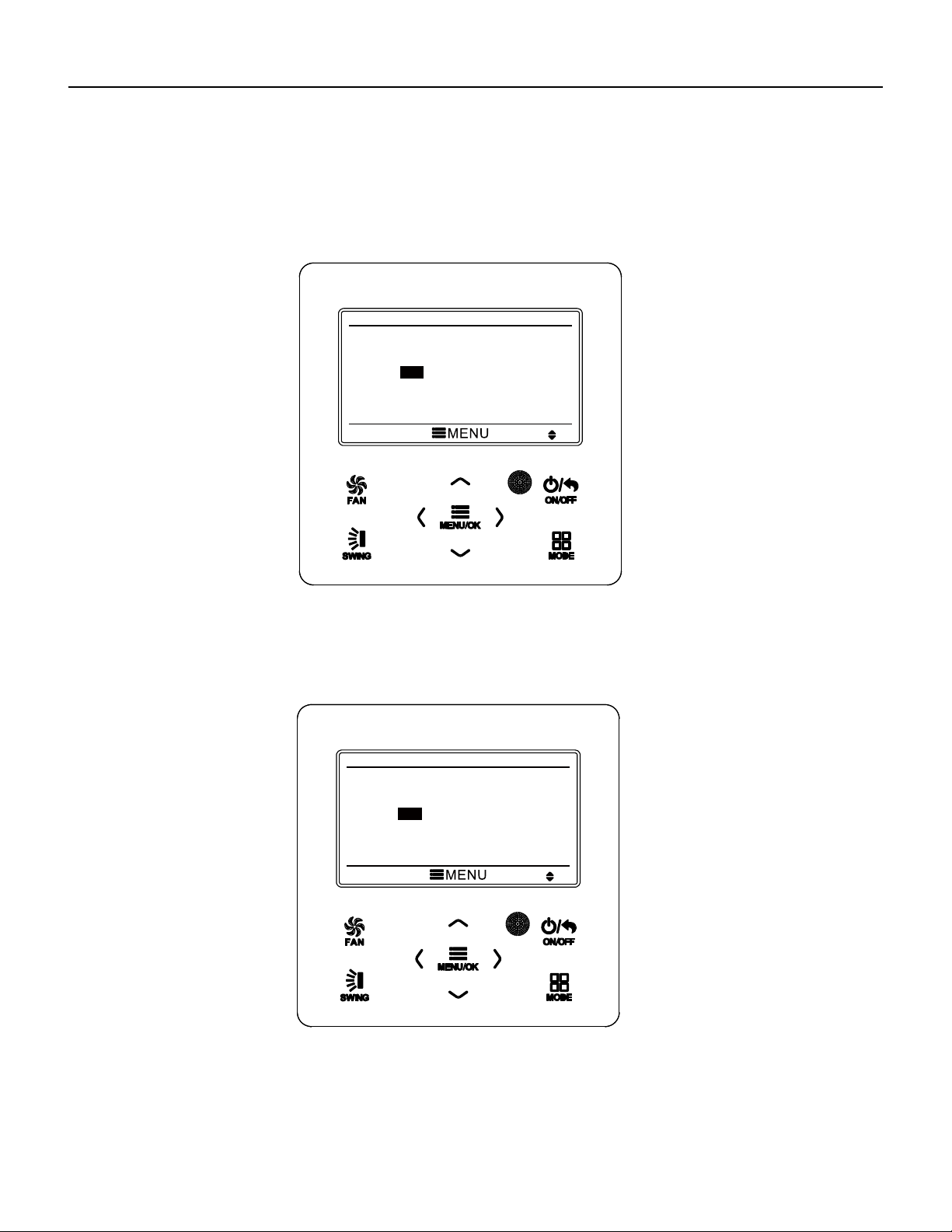
90 PB
Wired Controller FSWC1 Owner's Manual
After entering timer off setting page, press “
∧
” or “
∨
” button to increases or
decreases timer time by 0.5h. Press MENU button to save setting. Press BACK
button to return to the last page. Please refer to Fig. 17.
After entering timer on setting page, press “
∧
” or “
∨
” button to increases or
decreases timer time by 0.5h. Press MENU button to save setting. Press BACK
button to return to the last page. Please refer to Fig. 16.
19
Fig. 16 Countdown timer on
Fig. 17 Countdown timer off
If timer function is on, the set hours will decrease as the unit operation time
increases. In this case, residual hours can be viewed after entering timer setting page.
TIMER ON
0.5
HOURS ON
TIMER OFF
0.5
HOURS OFF
WIRED CONTROLLER
Operation Instructions
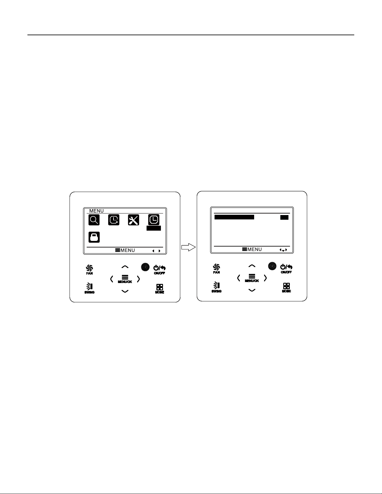
91 PB
Wired Controller FSWC1 Owner's Manual
20
This timer function will be carried out for only once and then it will be cancelled
automatically.
Note: If this timer function is turned on, when the unit is turned on or turned off, this
timer function will be cancelled automatically.
3.11 Clock Setting
3.11.1 Time Format Setting
The user can set the time format in 12-hour system or 24-hour system. Select
clock symbol in menu page and then press MENU button to enter clock setting page.
Press “
∧
” or “
∨
” button to select time format and then press “
<
” or “
>
” button to
select 1 2-hour system or 24-hour system. Please refer to Fig. 18.
Fig. 18 Time format selection
Note: If you need to use both the wired controller and remote controller,
please set the time of them identically.
3.11.2 Clock Setting
Select clock symbol in menu page and then press MENU button to enter clock
setting page. Press “
∧
” or “
∨
” button to select time set and then press MENU button to
enter time setting.
Press “
<
” or “
>
” button to select setting items: hour, minute, year, month, day;
press “
∧
” or “
∨
” button to set the value and then press MENU button to save setting.
Please refer to Fig. 19.
SEARCH
TIMER
FUNCTION
CLOCK
LOCK
CLOCK
CLOCK FORMAT
CLOCK
12
24
WIRED CONTROLLER
Operation Instructions
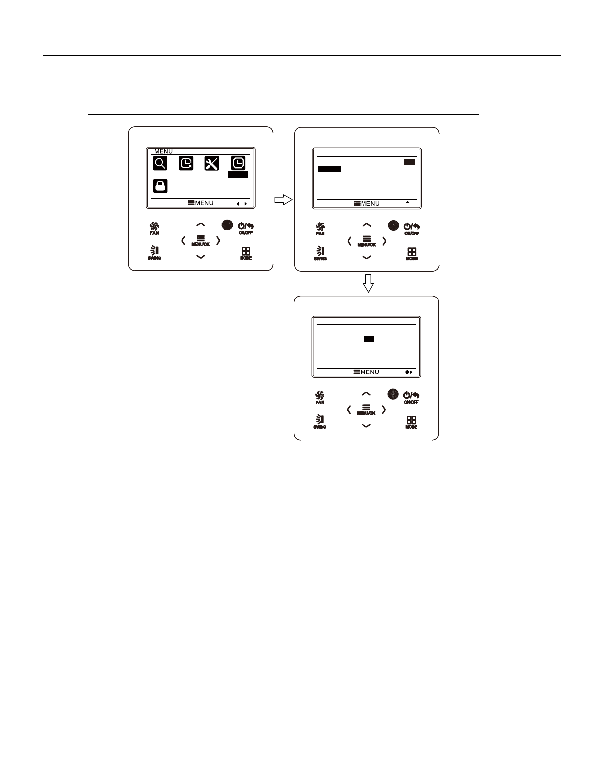
92 PB
Wired Controller FSWC1 Owner's Manual
21
Fig. 19 Clock setting
3.12 Lock Setting
Select lock symbol in menu page and then press MENU button to enter lock setting
page. Press “
∧
” or “
∨
” button to select the item to be locked and then press “
<
” or “
>
”
button to lock or unlock. Please refer to Fig. 20.
Items can be locked: ON/OFF, mode setting, temperature setting, fan speed
setting, key lock. After locking, the corresponding item cannot be set through buttons.
If the keys are locked, all keys cannot be operated after returning to the main page.
Please unlock according to the instructions on main page. During unlocking, press
MENU button, press “
<
” button and then press “
>
” button to unlock keys.
SEARCH
TIMER
FUNCTION
CLOCK
LOCK
CLOCK
CLOCK FORMAT
CLOCK
12
24
CLOCK
TIME : 12 :05
DATE : 2014/10/08
WIRED CONTROLLER
Operation Instructions
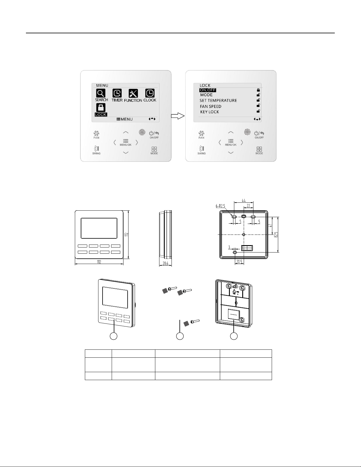
93 PB
Wired Controller FSWC1 Owner's Manual
22
Fig. 20 Lock setting
4 Installation Instructions
4.1 Parts and Dimension of Wired Controller
Fig. 21 Dimension of wired controller
Fig. 22 Parts of wired controller
No. 1 2
20 3
3
Name
Panel of wired
controller
Sponge 20
××
Soleplate of wired
controller
Quantity 1 3 1
31 2
unit:mm
Screw M4×25
WIRED CONTROLLER
Installation Instructions
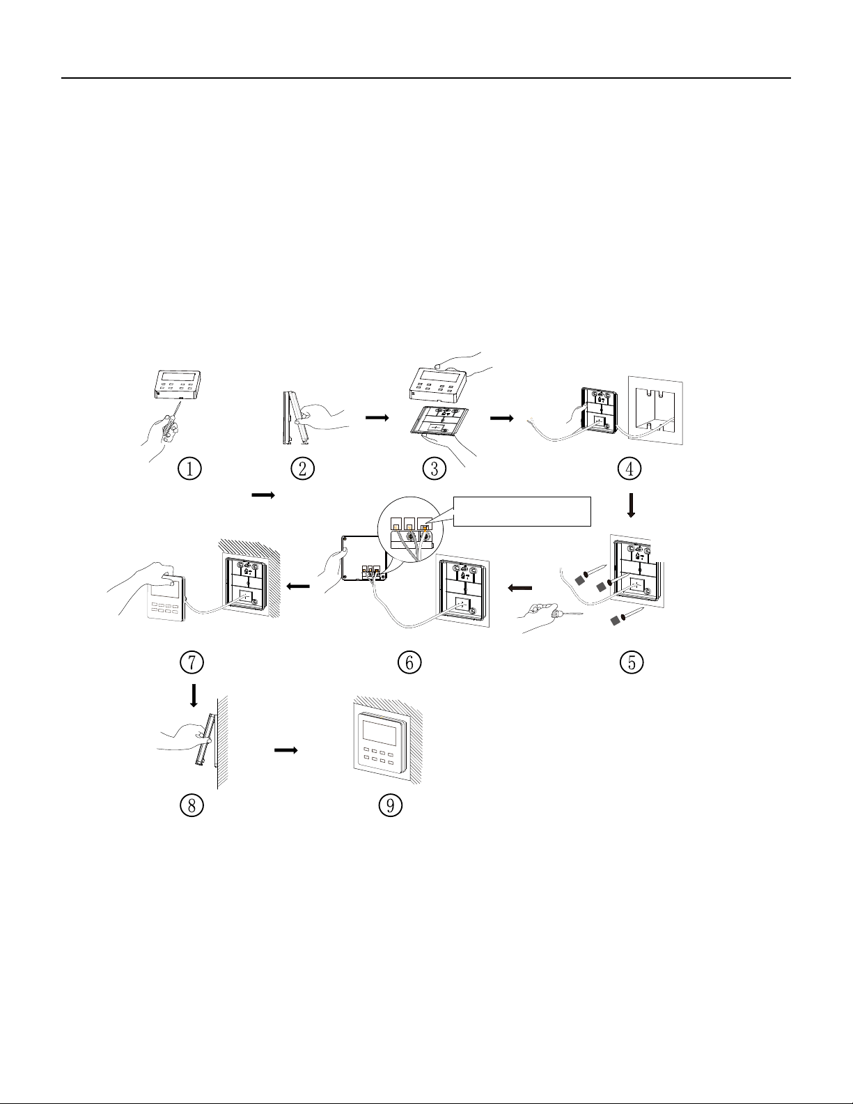
94 PB
Wired Controller FSWC1 Owner's Manual
23
4.2 Installation Requirements
(1) Prohibit installing the wired controller at wet places.
(2) Prohibit installing the wired controller at the places with direct sunshine.
(3) Prohibit installing the wired controller at the place near high temperature
objects or water-splashing places.
4.3 Installation Methods
Fig. 23 Installation diagram for wired controller
Fig. 23 is the simple installation process of wired controller; please pay attention to
the following items:
(1) Before installation, please cut off the power for indoor unit;
(2) Pull out the four-core twisted pair line from the installation holes and then let it go
through the rectangular hole behind the soleplate of the wired controller.
CN2
CN3CN4
CN2 terminal is used for connecting
indoor unit and it must be connected.
CN3 terminal and CN4 terminal are
used for connecting the centralized
controller, and these two terminals
have the same function. Customers
can select one or two terminal(s) for
connection according to the needs.
CN2
CN3CN4
WIRED CONTROLLER
Installation Instructions
CN4 CN3
CN2
.
CN4 CN3
CN2
NOTE:
CN2 terminal is used for connecting indoor unit and it must be connected.
CN3 terminal and CN4 terminal are used for connecting the centralized
controller, and these two terminals have the same function. Customers can
select one or two terminals for connection according to their requirements.
See NOTE Below
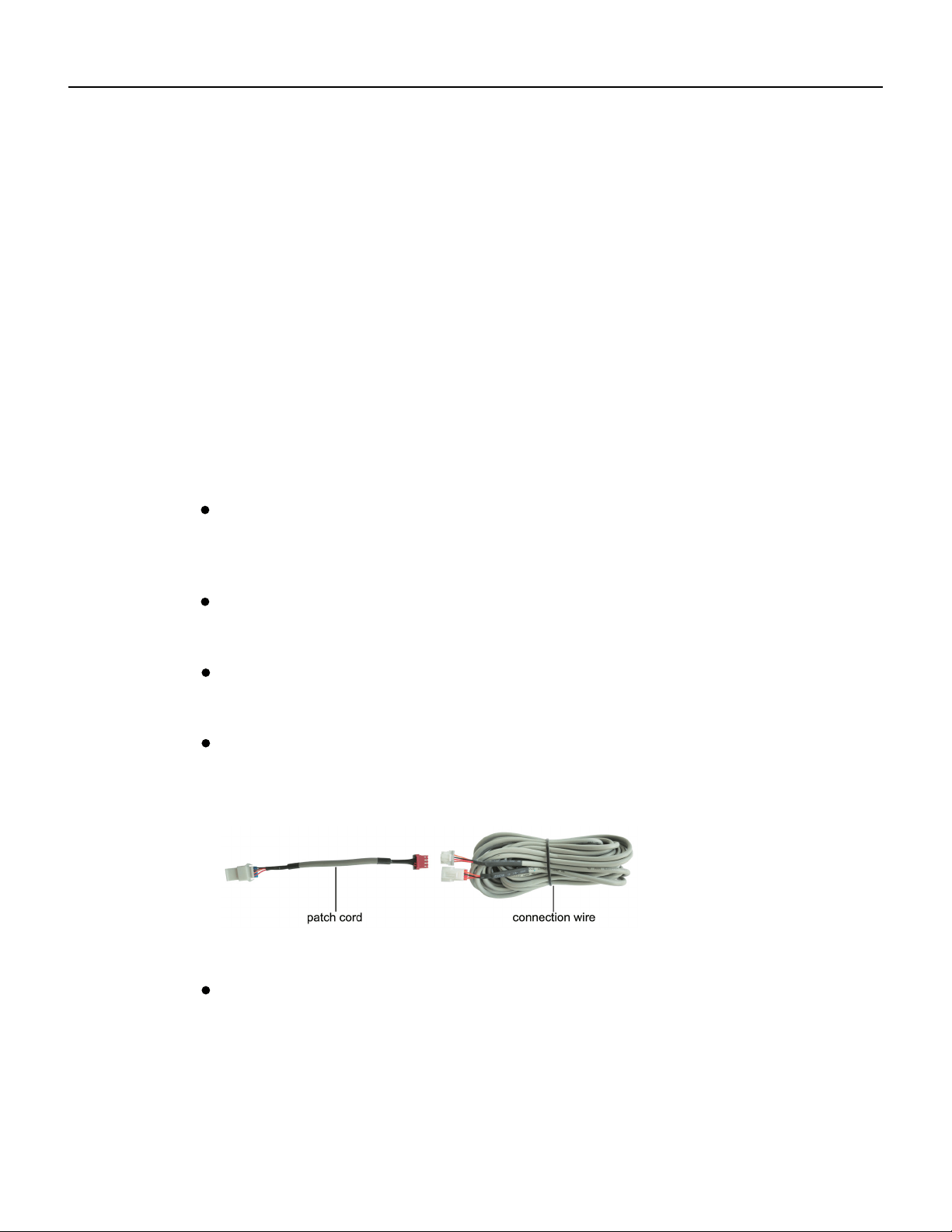
95 PB
Fig. A: Schematic diagram of patch cord and connection wire
Wired Controller FSWC1 Owner's Manual
(5) Block the four-core wire into the groove at the left side of wiring column; bundle
the front panel of wired controller to its soleplate.
24
Note:
the power cord and connection lines between the indoor and outdoor unit, with a
interference,then the signal and communication lines of the wired controller must
connects the centralized controller
(fig. C)
. The connecting method for the 2-core connection
wire is same as that of 4-core connection wire.
be the shielding twisted pair lines.
minimum interval of 20cm, otherwise the communication of the unit will probably
work abnormally.
Separate the signal and communication lines of the wired controller from
If the air conditioning unit is installed where is vulnerable to electromagnetic
No need
to set the wire of wired controller into the clasp.
The 4-core terminal connects the air conditioner, while the 2-core terminal
(3) Stick the soleplate of wired controller on the wall and then use screw M4×25 to fix
soleplate and installation hole on wall together, attach the sponge 20×20×3 at the
screw hole and then press it with fingers to make sure it’s attached firmly.
(4) Insert the four-core twisted pair line into the slot of the wired controller and then
buckle the front panel and the soleplate of the wired controller together.
If the air conditioner has been installed with the patch cord used for
connecting the wired controller.
For matching with different models, the patch cord and the connection
wire are provided in the packaging box of wired controller. As shown in fig. A.
NOTE:If a longer cable is needed, the cable can be cut and spliced utilizing
22x4AWG-THHN wire. This wire should be SHIELDED if running in areas where
there will be other wiring or electronics near the cable.
WIRED CONTROLLER
Installation Instructions
Fig. 23 Installation diagram for wired controller
Fig. 23 is the simple installation process of wired controller; please pay attention to
the following items:
(1) Before installation, please cut off the power for indoor unit;
(2) Pull out the four-core twisted pair line from the installation holes and then let it go
through the rectangular hole behind the soleplate of the wired controller.
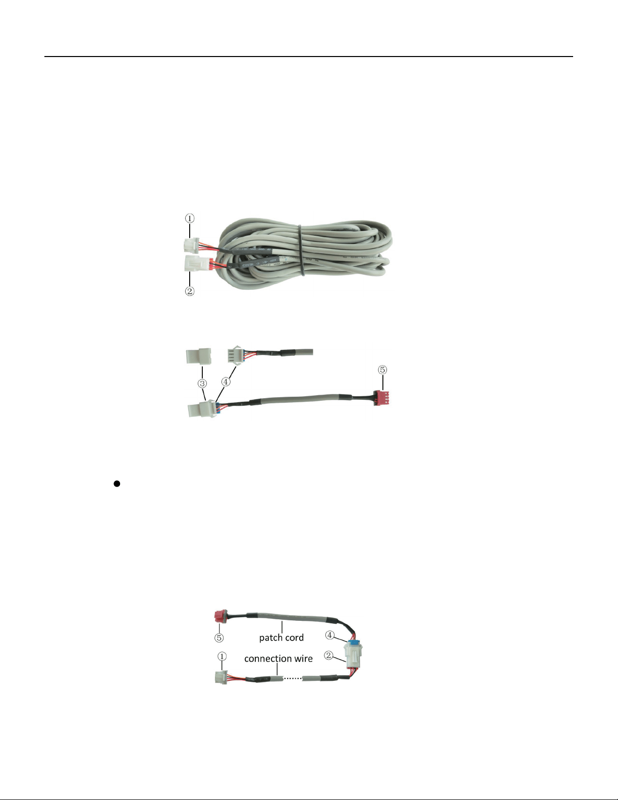
96 PB
Wired Controller FSWC1 Owner's Manual
Fig. B: Schematic diagram of connection wire: Connect terminal ① with wired
controller CN2; connect terminal ② with the terminal ④ of patch cord
Only use the connection wire (fig. B) in the packing box of wired controller.
Connect the terminal ② to the terminal ④ of patch cord which has been installed
on the air conditioner; insert terminal ① to needle stand CN2 of wired controller.
If there’s protection terminal ③, pull out the protection terminal at first and then
install it.
Use the connection wire and patch cord in the packing box of wired controller.
Pull out the protection terminal of patch cord at first, connect the connection wire
with the patch cord according to fig. D, and then insert the terminal ① of connection
wire into the needle stand CN2 of wired controller and insert the terminal ⑤ of patch
cord into the terminal of wired controller of air conditioner as well.
25
Fig. C: Schematic diagram of patch cord: Terminal ③ is the protection terminal;
connect terminal ④ to the terminal ② of connection wire ;connect
terminal ⑤ to the terminal of wired controller of air conditioner
Fig. D: Schematic diagram after the connection wire and the patch cord have
been connected: connect the terminal ② of connection wire and the
terminal ④ of patch cord
If the air conditioner hasn’t been installed with the patch cord used for
connecting the wired controller.
WIRED CONTROLLER
Installation Instructions
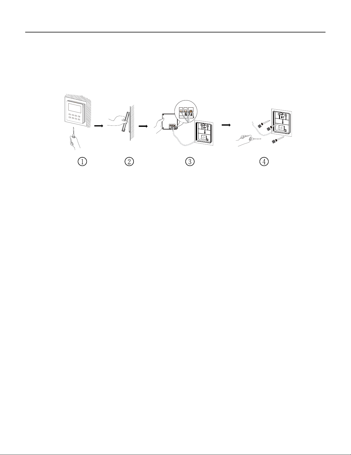
97 PB
26
Wired Controller FSWC1 Owner's Manual
4.4 Disassembly
Fig. 24 Disassembly diagram for wired controller
CN2
CN3CN4
CN2
CN3CN4
WIRED CONTROLLER
Installation Instructions
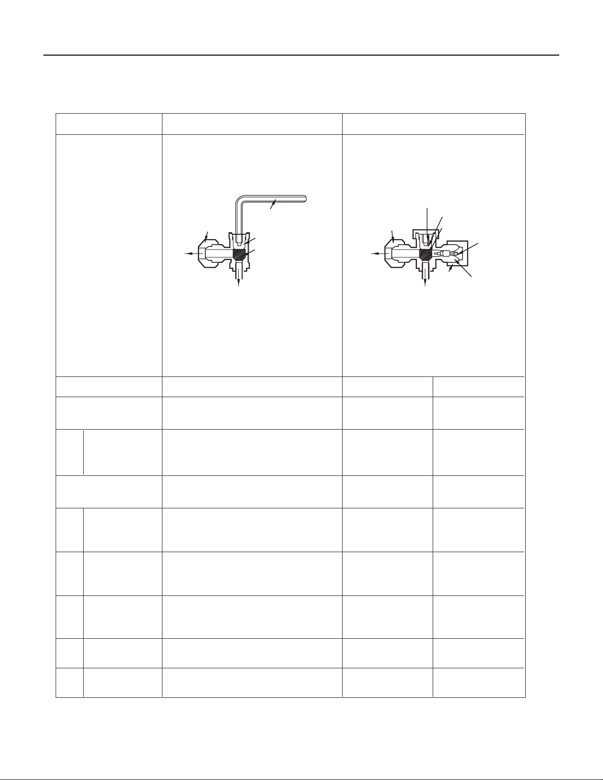
98 PB
R-410A SEALED SYSTEM REPAIR
Service Valves Appearance
2-way Valve (Liquid Side)
Shaft position
3-way Valve (Gas Side)
Shaft position Service port
Closed
Closed
(with cap)
Closed
(with valve cap)
Closed
(with valve cap)
Closed
(clockwise)
Closed
(with cap)
Open
(with valve cap)
Open
(with valve cap)
Closed
(clockwise)
gauge)
Open
Open Open
(counter-clockwise) (connected manifold
Open Open
(with charging
cylinder)
OpenOpen
Open
Open
(with charging
cylinder)
Open
OpenOpen
Shipping
Air purging
(Installation)
Operation
Evacuation
Pumping down
(Transfering)
(Servicing)
Gas charging
(Servicing)
Pressure check
(Servicing)
Gas releasing
(Servicing)
1.
2.
3.
4.
5.
6.
Valve cap
Open position
Closed position
Pin
Service
port
Service
port cap
To outdoor unit
Flare nut
To
piping
connection
To outdoor unit
Hexagonal wrench (4mm)
Open position
Closed position
To
piping
connection
Flare nut
Open
(with charging cylinder)
Open
(with charging cylinder)
(clockwise)
Open
(with vacumm pump)
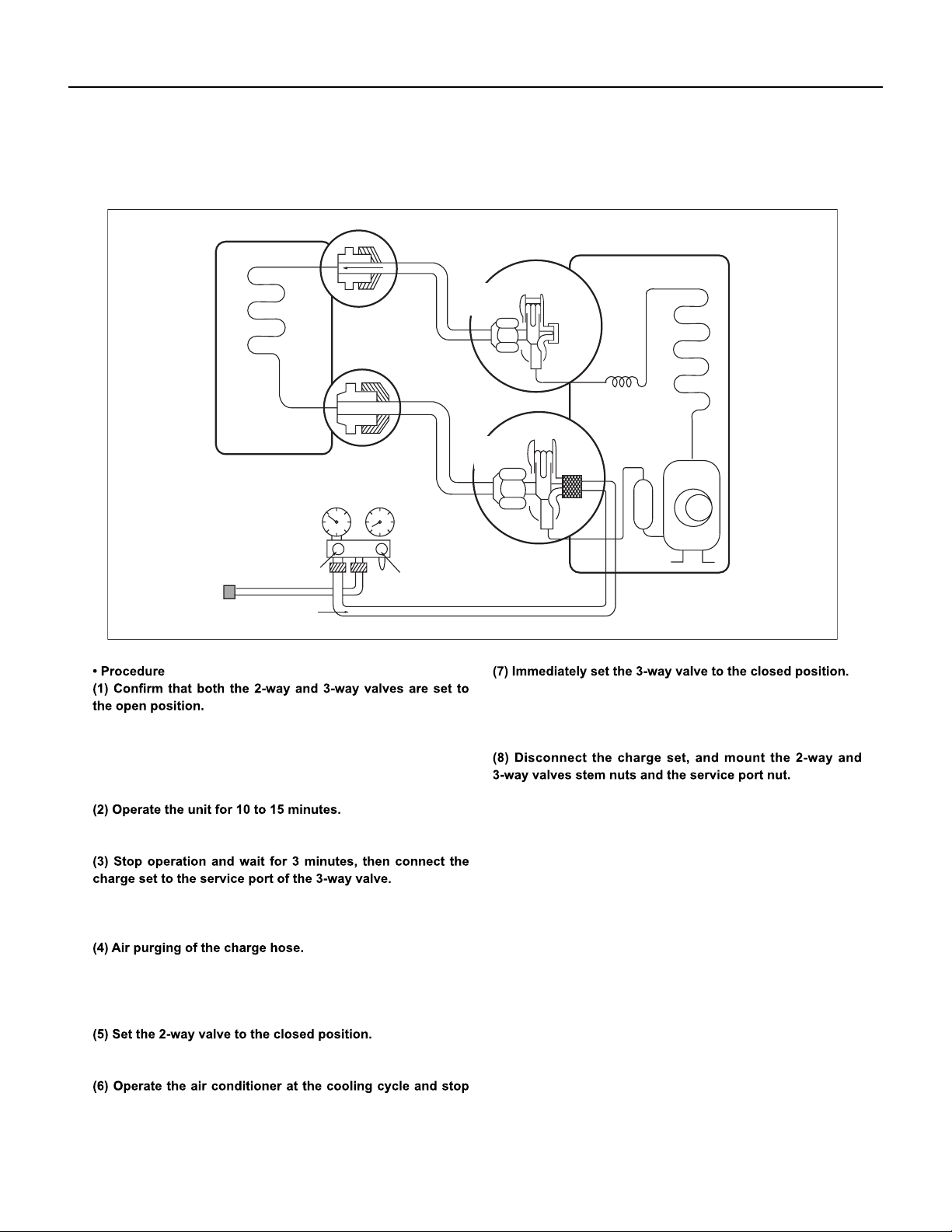
99 PB
R-410A SEALED SYSTEM REPAIR
Pumping Down
Lo
Closed
Purge the air
Outdoor unit
Indoor unit
Liquid side
Gas side
CLOSE
Open
2-Way
valve
CLOSE
3-Way
valve
– Remove the valve stem caps and confirm that the valve stems
are in the raised position.
– Be sure to use a hexagonal wrench to operate the valve stems.
– Connect the charge hose with the push pin to the service port.
– Open the low-pressure valve on the charge set slightly to air
purge from the charge hose.
– Do this quickly so that the gauge ends up indicating 0-15 PSI.
– Tighten the service port nut.
– Be sure to check for gas leakage.
when the guage indicates 0 psi.
Fig. 505
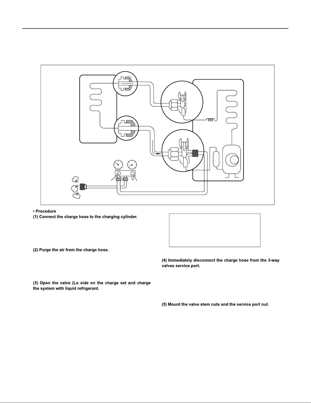
100 PB
R-410A SEALED SYSTEM REPAIR
Gas Charging (After Repair)
– Open the valve at the bottom of the cylinder and press the
– Connect the charge hose which you dis-connected from the
vacuum pump to the valve at the bottom of the cylinder.
– If you are using a gas cylinder, also use a scale and reverse
the cylinder so that the system can be charged with liquid.
check valve on the charge set to purge the air. (Be careful of
the liquid refrigerant).
–
–
Stopping partway will allow the gas to be discharged.
If the system has been charged with liquid refrigerant while
operating the air conditioner turn o the air conditioner before
disconnecting the hose.
– Tighten the service port nut.
– Be sure to check for gas leakage.
Lo
Open
Open
3-Way
valve
Gas side
CLOSE
3-Way
valve
OPEN
Outdoor unit
Liquid side
Indoor unit
This is different from previous procedures.
Because you are charging with liquid refrigerant
from the gas side, absolutely do not attempt to
charge with larger amounts of liquid refrigerant
while operating the air conditioner.
- Weigh in the refrigerant amount listed on the rating plate, adding
additional refrigerant as needed for long line set length.
- If the temperature does not allow full liquid charge, run the system
in air conditioning and throttle refrigerant in at 0.2 oz/min. Allow the
system pressure to stabilize each time.
Fig. 506
101 PB
COMPONENTS TESTING
Resistance Table of Ambient Temperature Sensor for Indoor and Outdoor Units (15kΩ)
Temp.
(°F)
Resistance
(kΩ)
Temp.
(°F)
Resistance(
kΩ)
Temp.
(°F)
Resistance
(kΩ)
Temp.
(°F)
Resistance
(kΩ)
‑2.2 138.1 68 18.75 138.2 3.848 208.4 1.071
‑0.4 128.6 69.8 17.93 140 3.711 210.2 1.039
1.4 121.6 71.6 17.14 141.8 3.579 212 1.009
3.2 115 73.4 16.39 143.6 3.454 213.8 0.98
5 108.7 75.2 15.68 145.4 3.333 215.6 0.952
6.8 102.9 77 15 147.2 3.217 217.4 0.925
8.6 97.4 78.8 14.36 149 3.105 219.2 0.898
10.4 92.22 80.6 13.74 150.8 2.998 221 0.873
12.2 87.35 82.4 13.16 152.6 2.896 222.8 0.848
14 82.75 84.2 12.6 154.4 2.797 224 3/5 0.825
15.8 78.43 86 12.07 156.2 2.702 226.4 0.802
17.6 74.35 87.8 11.57 158 2.611 228.2 0.779
19.4 70.5 89.6 11.09 159.8 2.523 230 0.758
21.2 66.88 91.4 10.63 161.6 2.439 231.8 0.737
23 63.46 93.2 10.2 163.4 2.358 233.6 0.717
24.8 60.23 95 9.779 165.2 2.28 235.4 0.697
26.6 57.18 96.8 9.382 167 2.206 237.2 0.678
28.4 54.31 98.6 9.003 168.8 2.133 239 0.66
30.2 51.59 100.4 8.642 170.6 2.064 240.8 0.642
32 49.02 102.2 8.297 172.4 1.997 242.6 0.625
33.8 46.6 104 7.967 174.2 1.933 244.4 0.608
35.6 44.31 105.8 7.653 176 1.871 246.2 0.592
37.4 42.14 107.6 7.352 177.8 1.811 248 0.577
39.2 40.09 109.4 7.065 179.6 1.754 249.8 0.561
41 38.15 111.2 6.791 181.4 1.699 251.6 0.547
42.8 36.32 113 6.529 183.2 1.645 253.4 0.532
44.6 34.58 114.8 6.278 185 1.594 255.2 0.519
46.4 32.94 116.6 6.038 186.8 1.544 257 0.505
48.2 31.38 118.4 5.809 188.6 1.497 258.8 0.492
50 29.9 120.2 5.589 190.4 1.451 260.6 0.48
51.8 28.51 122 5.379 192.2 1.408 262.4 0.467
53.6 27.18 123.8 5.197 194 1.363 264.2 0.456
55.4 25.92 125.6 4.986 195.8 1.322 266 0.444
57.2 24.73 127.4 4.802 197.6 1.282 267.8 0.433
59 23.6 129.2 4.625 199.4 1.244 269.6 0.422
60.8 22.53 131 4.456 201.2 1.207 271.4 0.412
62.6 21.51 132 4/5 4.294 203 1.171 273.2 0.401
64.4 20.54 134.6 4.139 204.8 1.136 275 0.391
66.2 19.63 136.4 3.99 206.6 1.103 276.8 0.382
102 PB
COMPONENTS TESTING
Resistance Table of Ambient Temperature Sensor for Indoor and Outdoor Units (20kΩ)
Temp.
(°F)
Resistance
(kΩ)
Temp.
(°F)
Resistance(
kΩ)
Temp.
(°F)
Resistance
(kΩ)
Temp.
(°F)
Resistance
(kΩ)
‑2.2 181.4 68 25.01 138.2 5.13 208.4 1.427
‑0.4 171.4 69.8 23.9 140 4.948 210.2 1.386
1.4 162.1 71.6 22.85 141.8 4.773 212 1.346
3.2 153.3 73.4 21.85 143.6 4.605 213.8 1.307
5 145 75.2 20.9 145.4 4.443 215.6 1.269
6.8 137.2 77 20 147.2 4.289 217.4 1.233
8.6 129.9 78.8 19.14 149 4.14 219.2 1.198
10.4 123 80.6 18.13 150.8 3.998 221 1.164
12.2 116.5 82.4 17.55 152.6 3.861 222.8 1.131
14 110.3 84.2 16.8 154.4 3.729 224 3/5 1.099
15.8 104.6 86 16.1 156.2 3.603 226.4 1.069
17.6 99.13 87.8 15.43 158 3.481 228.2 1.039
19.4 94 89.6 14.79 159.8 3.364 230 1.01
21.2 89.17 91.4 14.18 161.6 3.252 231.8 0.983
23 84.61 93.2 13.59 163.4 3.144 233.6 0.956
24.8 80.31 95 13.04 165.2 3.04 235.4 0.93
26.6 76.24 96.8 12.51 167 2.94 237.2 0.904
28.4 72.41 98.6 12 168.8 2.844 239 0.88
30.2 68.79 100.4 11.52 170.6 2.752 240.8 0.856
32 65.37 102.2 11.06 172.4 2.663 242.6 0.833
33.8 62.13 104 10.62 174.2 2.577 244.4 0.811
35.6 59.08 105.8 10.2 176 2.495 246.2 0.77
37.4 56.19 107.6 9.803 177.8 2.415 248 0.769
39.2 53.46 109.4 9.42 179.6 2.339 249.8 0.746
41 50.87 111.2 9.054 181.4 2.265 251.6 0.729
42.8 48.42 113 8.705 183.2 2.194 253.4 0.71
44.6 46.11 114.8 8.37 185 2.125 255.2 0.692
46.4 43.92 116.6 8.051 186.8 2.059 257 0.674
48.2 41.84 118.4 7.745 188.6 1.996 258.8 0.658
50 39.87 120.2 7.453 190.4 1.934 260.6 0.64
51.8 38.01 122 7.173 192.2 1.875 262.4 0.623
53.6 36.24 123.8 6.905 194 1.818 264.2 0.607
55.4 34.57 125.6 6.648 195.8 1.736 266 0.592
57.2 32.98 127.4 6.403 197.6 1.71 267.8 0.577
59 31.47 129.2 6.167 199.4 1.658 269.6 0.563
60.8 30.04 131 5.942 201.2 1.609 271.4 0.549
62.6 28.68 132 4/5 5.726 203 1.561 273.2 0.535
64.4 27.39 134.6 5.519 204.8 1.515 275 0.521
66.2 26.17 136.4 5.32 206.6 1.47 276.8 0.509
103 PB
COMPONENTS TESTING
Resistance Table of Ambient Temperature Sensor for Indoor and Outdoor Units (50kΩ)
Temp.
(°F)
Resistance
(kΩ)
Temp.
(°F)
Resistance(
kΩ)
Temp.
(°F)
Resistance
(kΩ)
Temp.
(°F)
Resistance
(kΩ)
‑20.2 853.5 50 98 120.2 18.34 190.4 4.754
‑18.4 799.8 51.8 93.42 122 17.65 192.2 4.609
‑16.6 750 53.6 89.07 123.8 16.99 194 4.469
‑14.8 703.8 55.4 84.95 125.6 16.36 195.8 4.334
‑13 660.8 57.2 81.05 127.4 15.75 197.6 4.204
‑11.2 620.8 59 77.35 129.2 15.17 199.4 4.079
‑9.4 580.6 60.8 73.83 131 14.62 201.2 3.958
‑7.6 548.9 62.6 70.5 132 4/5 14.09 203 3.841
‑5.8 516.6 64.4 67.34 134.6 13.58 204.8 3.728
‑4 486.5 66.2 64.33 136.4 13.09 206.6 3.619
‑2.2 458.3 68 61.48 138.2 12.62 208.4 3.514
‑0.4 432 69.8 58.77 140 12.17 210.2 3.413
1.4 407.4 71.6 56.19 141.8 11.74 212 3.315
3.2 384.5 73.4 53.74 143.6 11.32 213.8 3.22
5 362.9 75.2 51.41 145.4 10.93 215.6 3.129
6.8 342.8 77 49.19 147.2 10.54 217.4 3.04
8.6 323.9 78.8 47.08 149 10.18 219.2 2.955
10.4 306.2 80.6 45.07 150.8 9.827 221 2.872
12.2 289.6 82.4 43.16 152.6 9.489 222.8 2.792
14 274 84.2 41.34 154.4 9.165 224 3/5 2.715
15.8 259.3 86 39.61 156.2 8.854 226.4 2.64
17.6 245.6 87.8 37.96 158 8.555 228.2 2.568
19.4 232.6 89.6 36.38 159.8 8.268 230 2.498
21.2 220.5 91.4 34.88 161.6 7.991 231.8 2.431
23 209 93.2 33.45 163.4 7.726 233.6 2.365
24.8 198.3 95 32.09 165.2 7.47 235.4 2.302
26.6 199.1 96.8 30.79 167 7.224 237.2 2.241
28.4 178.5 98.6 29.54 168.8 6.998 239 2.182
30.2 169.5 100.4 28.36 170.6 6.761 240.8 2.124
32 161 102.2 27.23 172.4 6.542 242.6 2.069
33.8 153 104 26.15 174.2 6.331 244.4 2.015
35.6 145.4 105.8 25.11 176 6.129 246.2 1.963
37.4 138.3 107.6 24.13 177.8 5.933 248 1.912
39.2 131.5 109.4 23.19 179.6 5.746 249.8 1.863
41 125.1 111.2 22.29 181.4 5.565 251.6 1.816
42.8 119.1 113 21.43 183.2 5.39 253.4 1.77
44.6 113.4 114.8 20.6 185 5.222 255.2 1.725
46.4 108 116.6 19.81 186.8 5.06 257 1.682
48.2 102.8 118.4 19.06 188.6 4.904 258.8 1.64
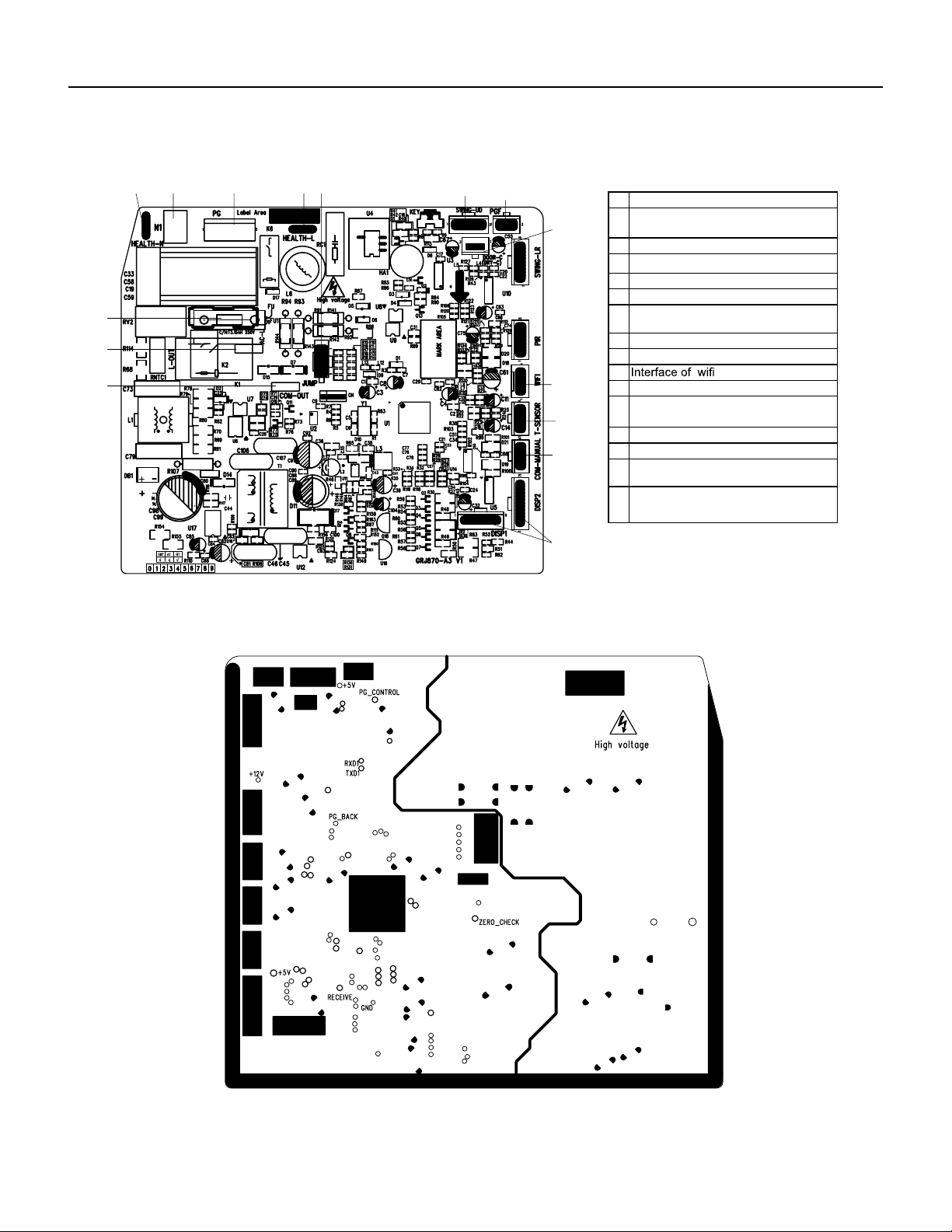
104 PB
COMPONENTS TESTING
Figure 701
9-12k Indoor Unit Printed Circuit Board Identification
No Name
1
2
Interface of communication wire for
indoor unit and outdoor unit
3
Interface of live wire
6
4
Interface of neutral wire
5
Interface of fan
Jumper cap
Interface of health function live wire
(only for the mode with this function)
9
10
7 Up&down swing interface
8
11
12
Feedback interface of indoor unit
13
Interface of tube temperature sensor
14
Wired controller
(only for the mode with this function)
15
Fuse
Display interface
Interface of gate control
(only for the mode with this function)
2
1
13
4
5
● Top view
15 3
6
87
9
10
14
11
12
Interface of health function neutral wire
(only for the mode with this function)
● Bottom view
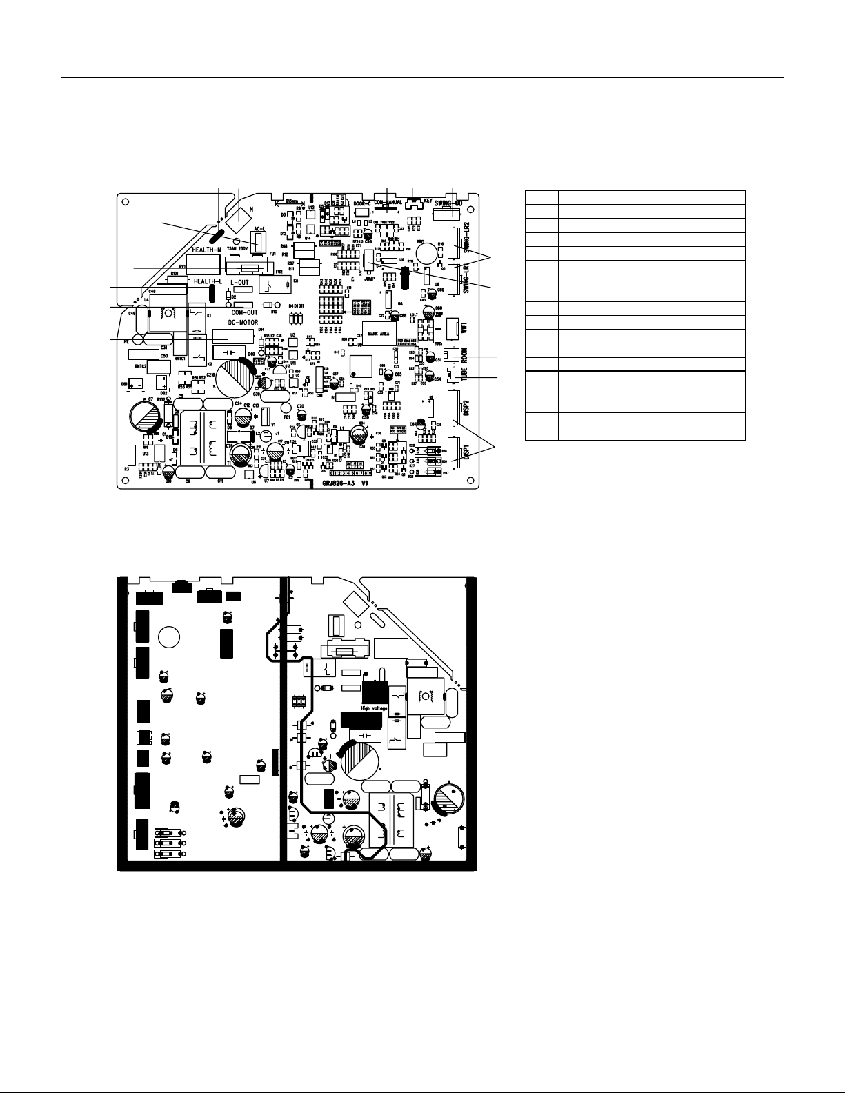
105 PB
COMPONENTS TESTING
Figure 702
18-24k Indoor Unit Printed Circuit Board Identification
Top view
Bottom view
No.
1
Name
Display interface
2
3
Inner tube temperature sensor
Ambient temperature sensor
4
5
Jumper cap
6
Left&right swing interface
Up&down swing interface
7
8
Auto button
9
Interface of wired controller
10
Neutral wire
11
Live wire
14
15
Fuse
12 Communication interface
13 Wiring terminal for DC motor
Interface of health function live wire
(only for the mode with this function)
Interface of health function neutral wire
(only for the mode with this function)
1
2
3
4
5
6
9
10
11
12
14
13
15
7
8
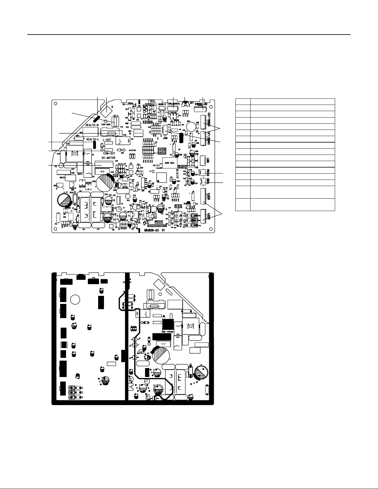
106 PB
COMPONENTS TESTING
Figure 703
36k Indoor Unit Printed Circuit Board Identification
Top view
Bottom view
No.
1
Name
Display interface
2
3
Inner tube temperature sensor
Ambient temperature sensor
4
5
Jumper cap
6
Left&right swing interface
Up&down swing interface
7
8
Auto button
9
Interface of wired controller
10
Neutral wire
11
Live wire
14
15
Fuse
12 Communication interface
13 Wiring terminal for DC motor
Interface of health function live wire
(only for the mode with this function)
Interface of health function neutral wire
(only for the mode with this function)
1
2
3
4
5
6
9
10
11
12
14
13
15
7
8
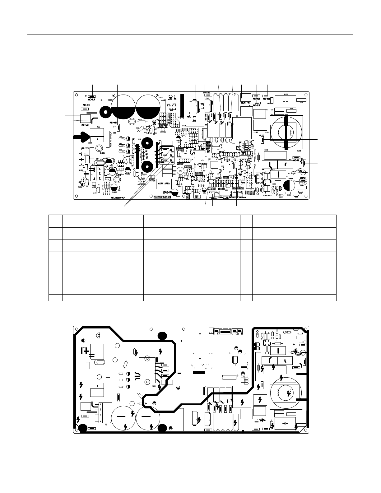
107 PB
COMPONENTS TESTING
Figure 704
9‑12k Outdoor Unit Printed Circuit Board Identification
● Bottom view
● Top view
6
8
7
9
1011
15 14 13
1217
16
19 18
20
21
22
1 2 3 4 5
NO. Name NO. Name NO. Name
1 Compressor output port 9 Live wire 17 Terminal of outdoor fan
2 Master control chip 10 18
Connection wire between boards of
neutral wire connects AC-N4
Connect the negative pole of external
big electrolytic capacitor
3 Overload temperature of compressor 11
Connection wire between boards of
live wire connects AC-L2
19
Connect the positive pole of external
big electrolytic capacitor
4 Temperature of temperature sensor 12
Neutral wire terminal for electric
heating
20
5
Wire connection terminal between
boards of neutral wire connects AC-N3
EEPROM 13
Live wire terminal for chassis electric
heater
21
Connection wire between boards of
live wire connects AC-L3
6 Communication wire port 14
Live wire terminal for compressor
electric heater
22
Connect the middle position of
external big electrolytic capacitor
7 Earthing wire port 15 4-way valve wiring terminal /
8 Port of power neutral wire 16 Terminal of electronic expansion valve /
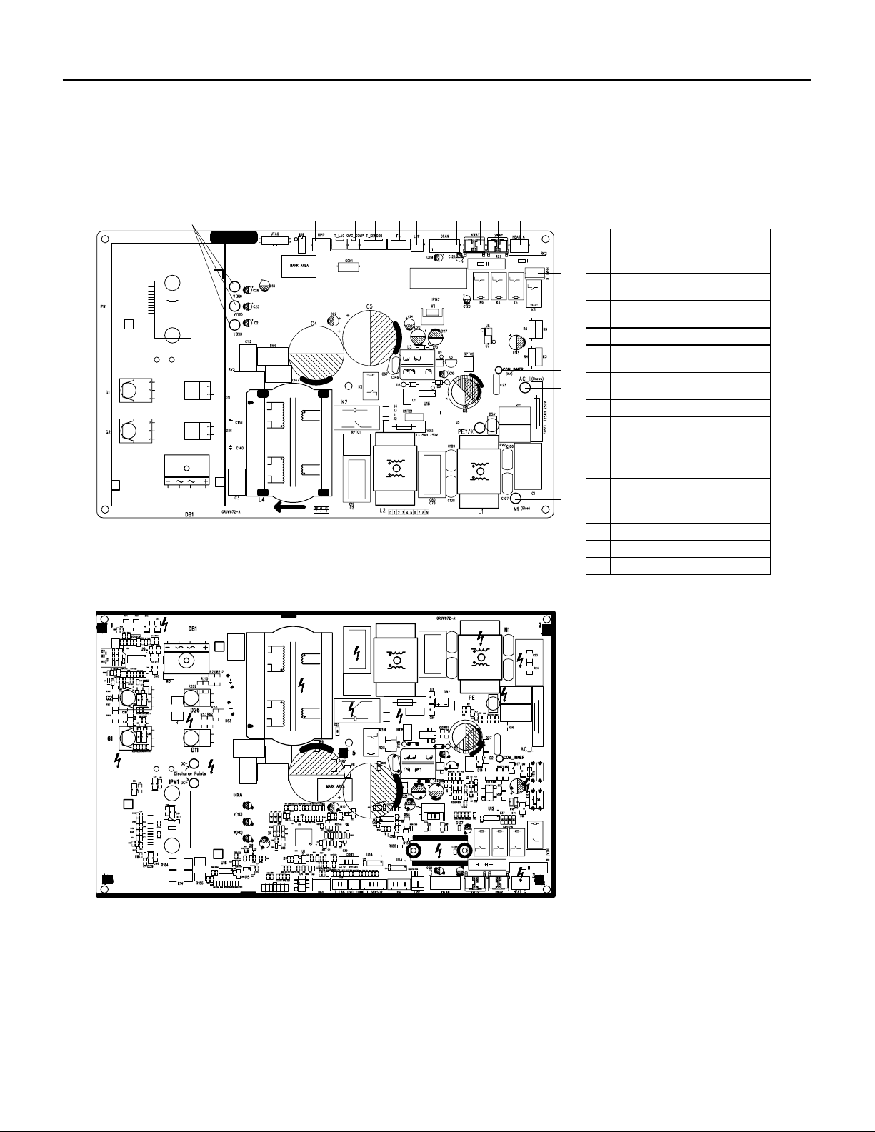
108 PB
COMPONENTS TESTING
Figure 705
18‑24k Outdoor Unit Printed Circuit Board Identification
Outdoor Unit
No. N mea
1
2
Compressor three phase input
interface
3
Interface of system high pressure
protection
5
Interface of electronic expansion
valve
4
Compressor overload protection
interface
6
Interface of temperature sensor
7
Interface of system low pressure
protection
8
Interface of fan
10
11
4-way valve interface
9
12
2-way valve interface
14
Communication interface
13 Interface of live wire
Interface of earthing wire
15 Interface of netural wire
● Top view
● Bottom view
1 2 3 4 65 7 98
Interface of electric heating for
compressor
10
11
12
13
14
15
Interface of electric heating for
chassis
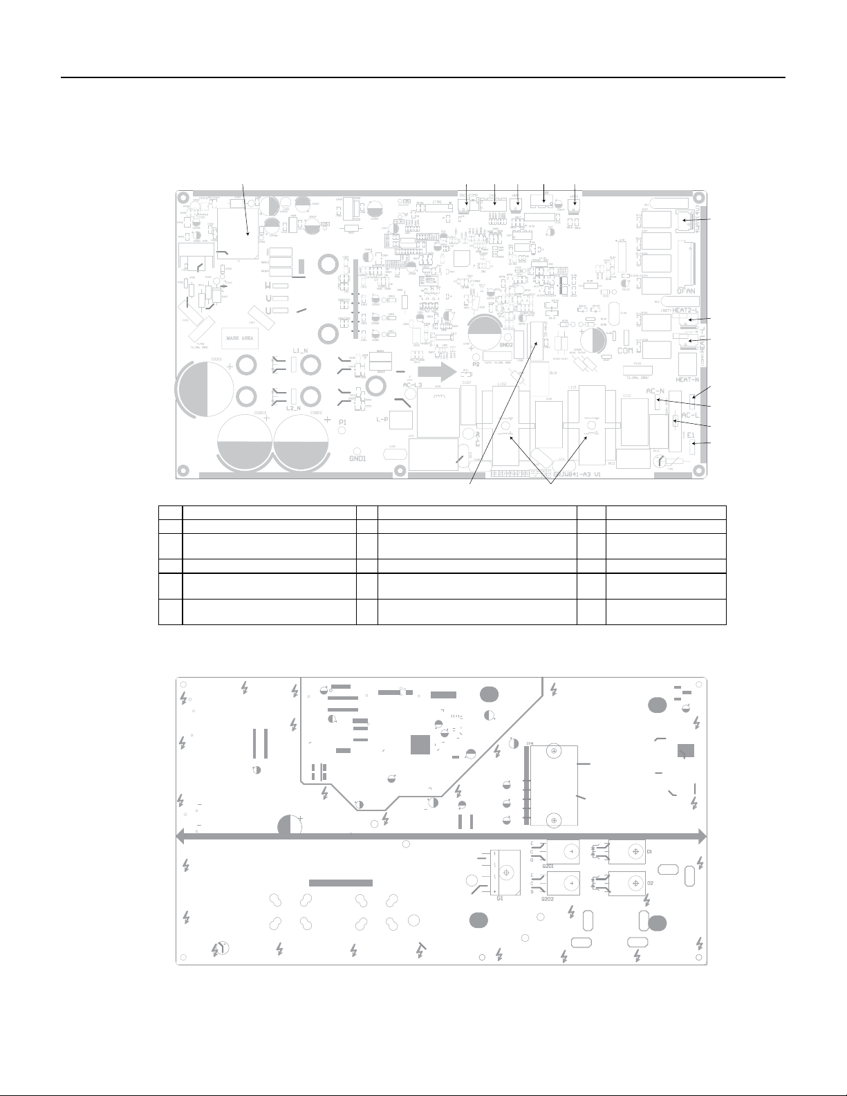
109 PB
COMPONENTS TESTING
Figure 706
36k Outdoor Unit Printed Circuit Board Identification
● Top view
● Bottom view
No. Name No. Name No. Name
1 High-frequency transformer T1 6 High pressure protection terminal HPP1 11 Terminal of neutral wire
2
Overload protection terminal of
compressor OVC-COMP
7 Terminal of 4-way valve 12 Protective tube FU101
3 Terminal of temp sensor CN2 8 Electric heater band of chassis HEAT2-L 13 Terminal of ground wire
4
High pressure protection terminal
HPP
9
Electric heater band of compressor
HEAT1-L
14 Choke L 101 and L102
5
Electronic expansion valve terminal
EV
10 Terminal of live wire 15
Terminal of outdoor fan
OFAN-DC
1 2 3 4 5 6
7
8
9
10
11
12
13
1415
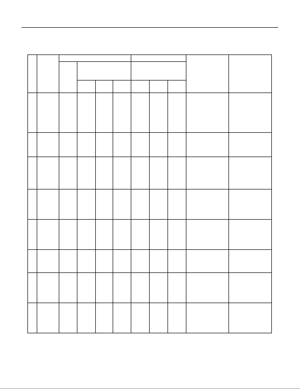
110 PB
TROUBLESHOOTING
Diagnostic Codes
No. Malfunction
Name
Display Method of Indoor Unit Display Method of Outdoor Unit A/C status Possible Causes
Dual‑8
Code
Display
Indicator Display (During blinking,
ON 0.5s and OFF 0.5s)
Indicator has 3 kinds of display status
and during blinking, ON 0.5s and
OFF 0.5s
Power
Indicator
Cool
Indicator
Heating
Indicator
Yellow
Indicator
Red
Indicator
Green
Indicator
1 High
Pressure
Protectioon
Of System
E1 OFF 3s
and blink
once
During cooling and drying
operation, except indoor
fan operates, all loads stop
operation.
During heating operation, the
complete unit stops.
Possible reasons:
1.Refrigerant was super‑
abundant;
2.Poor heat exchange
(including filth blockage of
heat exchanger and bad
radiating environment );
Ambient temperature is
too high.
2 Antifreezing
protection
E2 OFF 3s
and blink
twice
OFF 1 s
and blink 3
times
During cooling and drying
operation, compressor and
outdoor fan stop while indoor
fan operates.
1.Poor air‑return in indoor
unit;
2.Fan speed is abnormal;
3.Evaporator is dirty.
3 In Defect of
refrigerant
F0 OFF 1 s
and blink 9
times
The Dual‑8 Code Display will
show F0 and the complete
unit stops.
1.In defect of refrigerant;
2.Indoor evaporator
temperature sensor works
abnormally;
3. The unit has been
plugged up somewhere.
4 High
Discharge
temperaature
protection of
compressor
E4 OFF 3s
and blink 4
times
OFF 1s
and blink 7
times
During cooling and drying
operation, compressor and
outdoor fan stop while indoor
fan operates. During heating
operation, all loads stop.
Please refer to the malfunc‑
tion analysis (discharge
protection, overload).
5 Overcurrent
protection
E5 OFF 3s
and blink 6
times
OFF 1s
and blink 5
times
During cooling operation,
compressor stops while
indoor fan motor operates.
During heating operation, the
complete unit stops.
1. Supply voltage is unstable;
2. Supply voltage is too low
andload is too high;
3. Evaporator is dirty.
6 Communica‑
tion malfunc‑
tion
E6 OFF 3s
and blink 6
times
Always on During cooling operation,
compressor stops while
indoor fan motor operates.
During heating operation,
the complete unit stops.
Refer to the corresponding
malfunction analysis.
7 High
temperature
resistant
prtoection
E8 OFF 3s
and blink 8
times
OFF 1s
and blink 6
times
During cooling operation:
compressor will stop while
indoor fan will operate.
During heating operation, the
complete unit stops.
Refer to the malfunction
analysis (overload, high
temperature resistant).
8 EEPROM
malfunction
EE OFF 3s
and blink
15 times
OFF 1s
and blink
11 times
During cooling and drying op‑
eration, compressor will stop
while indoor fan will operate;
During heating operation, the
complete unit will stop
Replace outdoor control
panel AP1
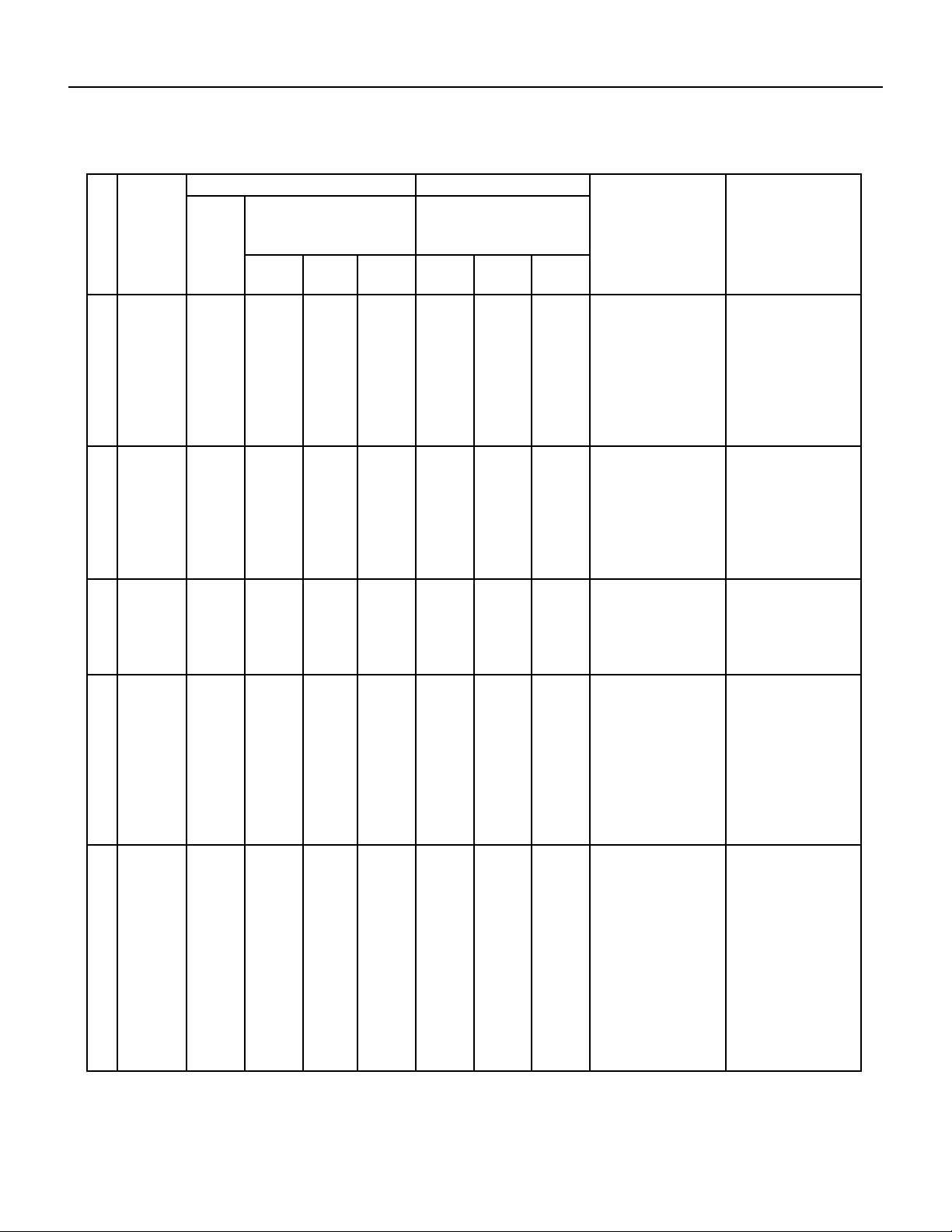
111 PB
TROUBLESHOOTING
Diagnostic Codes
No. Malfunction
Name
Display Method of Indoor Unit Display Method of Outdoor Unit A/C status Possible Causes
Dual‑8
Code
Display
Indicator Display (During blinking,
ON 0.5s and OFF 0.5s)
Indicator has 3 kinds of display status
and during blinking, ON 0.5s and
OFF 0.5s
Power
Indicator
Cool
Indicator
Heating
Indicator
Yellow
Indicator
Red
Indicator
Green
Indicator
9 Limit/
decrease
frequency
due to high
temperature
EU OFF 3s
and blink
6 times
OFF 3s
and blink
6 times
All loads operate normally,
while
operation frequency for
compressor is decreased
Discharging after the
complete unit is de‑energized
for 20mins, check whether
the thermal grease on IPM
Module of outdoor control
the radiator is inserted tightly.
If its no use, please replace
control panel AP1.
10 Malfunction
protection of
jumper cap
C5 OFF 3s
and blink
15 times
Wireless remote receiver
and button are effective, but
can not dispose the related
command
1.No jumper cap insert on
mainboard.
2.Incorrect insert of jumper
cap.
3.Jumper cap damaged.
4.Abnormal detecting circuit of
mainboard.
11 Gathering
Refrigerant
F0 OFF 3s
and blink
once
OFF 3s
and blink
once
OFF 1s
and blink
17 times
When the outdoor unit receive
signal of Gathering refrigerant
,the system will be forced to
run under cooling mode for
gathering refrigerant
Nominal cooling mode
12 Indoor ambi‑
ent tempera‑
ture sensor is
open/ short
circuited
F2 OFF 3s
and blink
once
During cooling and drying
operation, indoor unit oper‑
ates while other loads will
stop; during heating operation,
the complete unit will stop
operation.
1.Loosening or bad contact of
indoor ambient temp. sensor
and mainboard terminal.
2.Components in mainboard
fell down leads short circuit.
3.Indoor ambient temp.
sensor damaged.(check with
sensor resistance value chart)
4.Mainboard damaged.
13 indoor
evaporator
temperature
sensor is
open/ short
circuted
F2 OFF 3s
and blink
twice
AC stops operation once
reaches the setting tempera‑
ture. Cooling, drying: internal
fan motor stops operation
while other loads stop
operation; heating: AC stop
operation
1.Loosening or bad contact
of Indoor
evaporator temp. sensor and
mainboard terminal.
2.Components on the
mainboard fall down leads
short circuit
3.Indoor evaporator temp.
sensor damaged.(check temp.
sensor value
chart for testing)
4.Mainboard damaged.
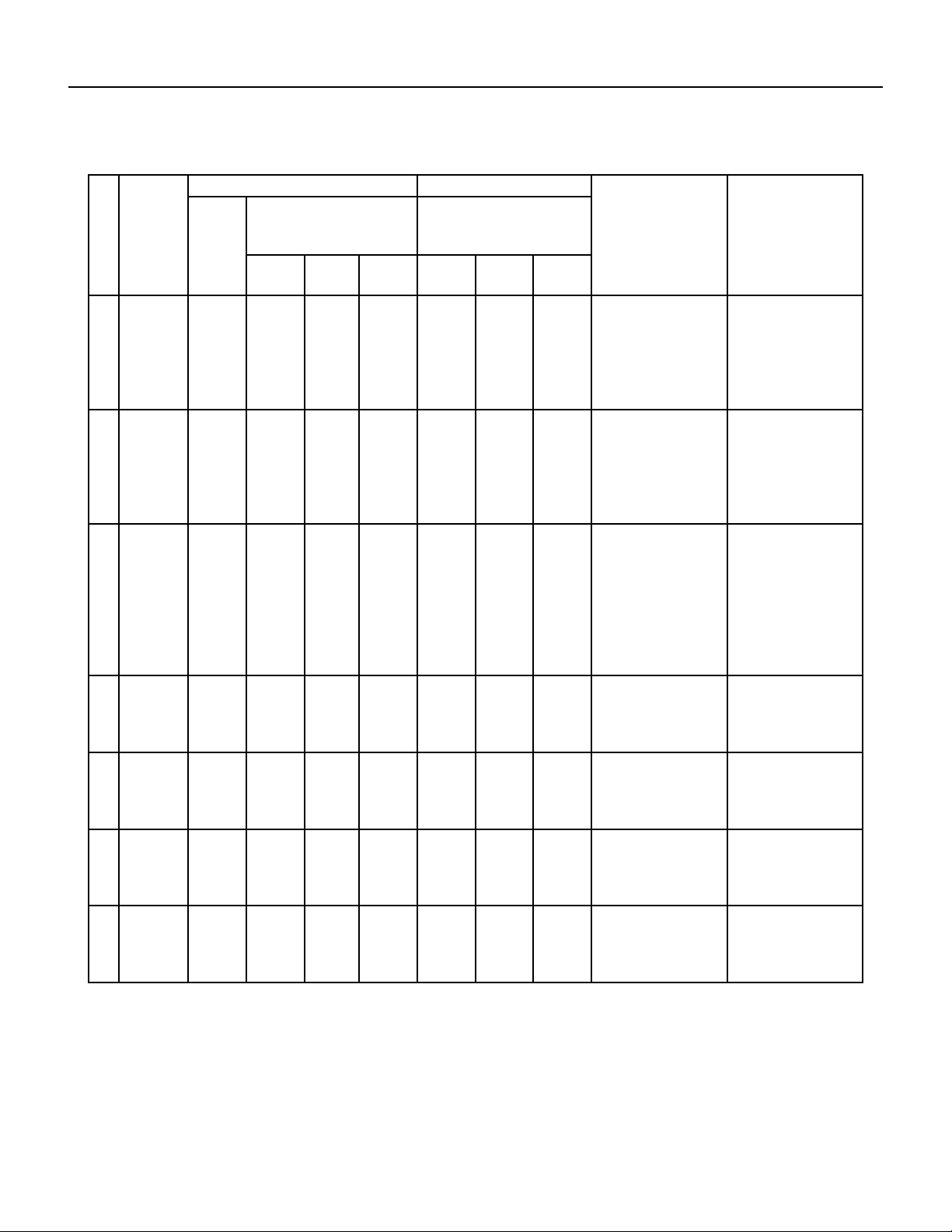
112 PB
No. Malfunction
Name
Display Method of Indoor Unit Display Method of Outdoor Unit A/C status Possible Causes
Dual‑8
Code
Display
Indicator Display (During blinking,
ON 0.5s and OFF 0.5s)
Indicator has 3 kinds of display status
and during blinking, ON 0.5s and
OFF 0.5s
Power
Indicator
Cool
Indicator
Heating
Indicator
Yellow
Indicator
Red
Indicator
Green
Indicator
14 outdoor
ambient
temperature
sensor is
open/ short
circuted
F3 OFF 3s
and blink
3 times
OFF 1s
and blink 6
times
During cooling and drying
operating, compressor stops
while indoor fan operates;
During heating operation,
the complete unit will stop
operation
Outdoor temperature sensor
hasnt’ been connected well or
is damaged. Please check it
by referring to the resistance
table for temperature sensor)
15 outdoor
condenser
temperature
sensor is
open/ short
circuted
F4 OFF 3s
and blink
4 times
OFF 1s
and blink 5
times
During cooling and drying
operation, compressor stops
while indoor fan will operate;
During heating operation,
the complete unit will stop
operation.
Outdoor temperature sensor
hasnt been connected well or
is damaged. Please check it
by referring to the resistance
table for temperature sensor
16 outdoor
discharge
temperature
sensor is
open/ short
circuted
F5 OFF 3s
and blink
for 5
times
OFF 1S
and blink 7
times
During cooling and drying
operation, compressor will
sop after operating for about
3 mins,
while indoor fan will operate;
During heating operation, the
complete unit will stop after
operating for about 3 mins.
1. Outdoor temperature sen‑
sor hasnt been connected well
or is damaged. Please check it
by referring to the resistance
table for temperature sensor
2. The head of temperature
sensor hasnt been inserted
into the copper tube
17 limit/
decrease fre‑
quency due to
overload
F6 OFF 3s
and blink
for 6
times
OFF 1s
and blink 3
times
All loads operate normally,
while
operation frequency for
compressor is decreased
Refer to the malfunction
analysis (overload, high
temperature resistant)
18 decrease fre‑
quency due to
overcurrent
F8 OFF 3s
and blink
8 times
OFF 1s
and blink
once
All loads operate normally,
while
operation frequency for
compressor is decreased
The input supply voltage is too
low; System pressure is too
high and overload
19 decrease
frequency
due to high
air discharge
F9 OFF 3s
and blink
9 times
OFF 1s
and blink
twice
All loads operate normally,
while
operation frequency for
compressor is decreased
Overload or temperature is
too high; refrigerant is insuf‑
ficent Malfunction of electric
expansion valve (EKV)
20 limit/
decrease fre‑
quency due to
antifreezing
FH OFF 3s
and blink
2 times
OFF 3s
and blink 2
times
OFF 1s
and blink 4
times
All loads operate normally,
while operation frequency for
compressor is decreased
Poor air‑return in indoor unit
or fan speed is too low
TROUBLESHOOTING
Diagnostic Codes
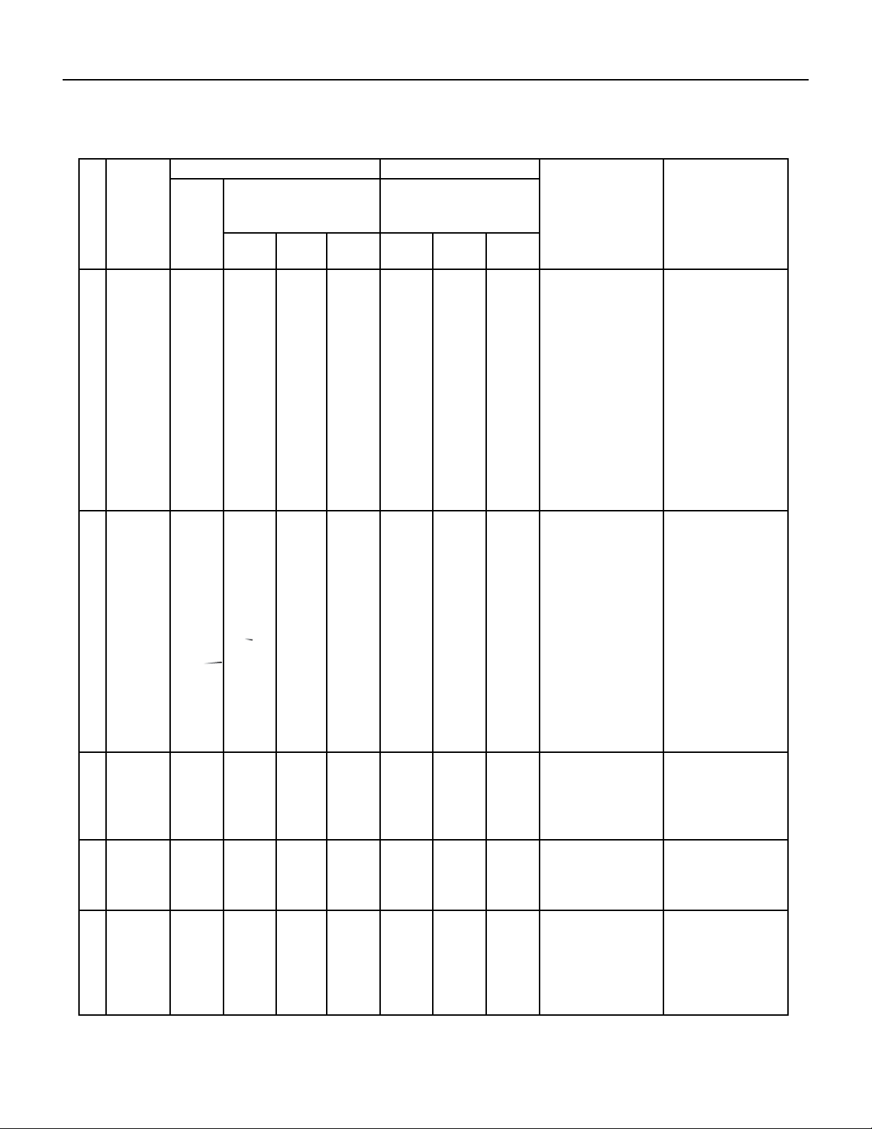
113 PB
No. Malfunction
Name
Display Method of Indoor Unit Display Method of Outdoor Unit A/C status Possible Causes
Dual‑8
Code
Display
Indicator Display (During blinking,
ON 0.5s and OFF 0.5s)
Indicator has 3 kinds of display status
and during blinking, ON 0.5s and
OFF 0.5s
Power
Indicator
Cool
Indicator
Heating
Indicator
Yellow
Indicator
Red
Indicator
Green
Indicator
21 voltage for
DC bus bar is
too high high
PH OFF 3s
and blink
11 times
OFF 1s
and blink
13 times
During cooling and drying op‑
eration, compressor will stop
while indoor fan will operate;
During heating operation,
the complete unit will stop
operation.
1.Measure the voltage of
position L and N on wiring
board (XT), if the voltage is
higher than 265VAC, turn
on the unit after the supply
voltage is increased to the
normal range.
2.If the AC input is normal,
measure the voltage of
electrolytic capacitor C on
control panel (AP1), if its
normal, theres malfunction for
the circuit, please replace the
control panel (AP1)
22 voltage of DC
bus‑ bar is
too low
PL OFF 3s
and blink
21 times
OFF 1s
and blink
12 times
During cooling and drying op‑
eration, compressor will stop
while indoor fan will operate;
During heating operation, the
complete unit will stop
1.Measure the voltage of
position L and N on wiring
board (XT), if the voltage is
higher than 150VAC, turn
on the unit after the supply
voltage is increased to the
normal range.
2.If the AC input is normal,
measure the voltage of elec‑
trolytic capacitor C on control
panel (AP1), if its normal,
there is a malfunction for the
circuit, replace the control
panel (AP1)
23 compres‑
sor min
frequence in
test state
P0 during
blinking
ON 0.25s
and OFF
0.25s
during
blinking
ON 0.25s
and OFF
0.25s
Showing during nominal cool‑
ing or nominal heating test
24 compres‑
sor rated
frequence in
test state
P1 during
blinking
ON 0.25s
and OFF
0.25s
during
blinking
ON 0.25s
and OFF
0.25s
Showing during middle cool‑
ing or middle heating test
25 compressor
maximum
frequence in
test state
P2 during
blinking
ON and
0.25s and
OFF and
0.25s
during
blinking
ON and
0.25s and
OFF and
0.25s
Showing during max. cooling
or max. heating test
TROUBLESHOOTING
Diagnostic Codes
114 PB
No. Malfunction
Name
Display Method of Indoor Unit Display Method of Outdoor Unit A/C status Possible Causes
Dual‑8
Code
Display
Indicator Display (During blinking,
ON 0.5s and OFF 0.5s)
Indicator has 3 kinds of display status
and during blinking, ON 0.5s and
OFF 0.5s
Power
Indicator
Cool
Indicator
Heating
Indicator
Yellow
Indicator
Red
Indicator
Green
Indicator
26 compressor
intermediate
frequence in
test state
P3 during
blinking
ON and
0.25s and
OFF and
0.25s
during
blinking
ON and
0.25s and
OFF and
0.25s
Showing during middle cool‑
ing or middle heating test
27 overcurrent
protection of
phase current
for compres‑
sor
P5 OFF 3s
and blink
15 times
During cooling and drying op‑
eration, compressor will stop
while indoor fan will operate;
During heating operation,
the complete unit will stop
operation.
Refer to the malfunction
analysis (IPM protection, loss
of synchronism protection
and overcurrent protection of
phase current for compres‑
sor).
28 charging
malfunction
of capacitor
PU OFF 3s
and blink
17 times
During cooling and drying op‑
eration, compressor will stop
while indoor fan will operate;
During heating operation, the
complete unit will stop
Refer to the part three—charg‑
ing malfunction analysis of
capacitor
29 malfunction
of module
temperature
sensor circuit
P7 OFF 3s
and blink
18 times
s During cooling and drying op‑
eration, compressor will stop
while indoor fan will operate;
During heating operation, the
complete unit will stop
Replace outdoor control
panel AP1
30 module high
temperature
protection
P8 OFF 3s
and blink
19 times
During cooling operation,
compressor will stop while
indoor fan will operate;
During heating operation, the
complete unit will stop
After the complete unit is de‑
energized for 20mins, check
whether the thermal grease
on IPM Module of outdoor
control panel AP is sufficient
and whether the radiator is
inserted tightly. If no faults
found, replace control panel
AP1
31 decrease
frequency
due to high
temperature
resistant dur‑
ing heating
operation
H0 OFF 3s
and blink
10 times
All loads operate normally,
while
operation frequency for
compressor is decreased
Refer to the malfunction
analysis (overload, high
temperature resistant)
32 static dedust‑
ing protection
H2 OFF 3s
and blink
twice
TROUBLESHOOTING
Diagnostic Codes
115 PB
TROUBLESHOOTING
Diagnostic Codes
No. Malfunction
Name
Display Method of Indoor Unit Display Method of Outdoor Unit A/C status Possible Causes
Dual‑8
Code
Display
Indicator Display (During blinking,
ON 0.5s and OFF 0.5s)
Indicator has 3 kinds of display status
and during blinking, ON 0.5s and
OFF 0.5s
Power
Indicator
Cool
Indicator
Heating
Indicator
Yellow
Indicator
Red
Indicator
Green
Indicator
33 overload
protection
for compres‑
sor
H3 OFF 3s
and blink
3 times
OFF 1s
and blink
8 times
During cooling and drying op‑
eration, compressor will stop
while indoor fan will operate;
During heating operation,
the complete unit will stop
operation.
1.Wiring terminal OVC‑COMP
is loosened. In normal state,
the resistance for this terminal
should be less than 1ohm.
2.Refer to the malfunction
analysis ( discharge protec‑
tion, overload)
34 system is
abnormal
H4 OFF 3s
and blink
4 times
OFF 1s
and blink
6 times
During cooling and drying op‑
eration, compressor will stop
while indoor fan will operate;
During heating operation,
the complete unit will stop
operation.
Refer to the malfunction
analysis (overload, high
temperature resistant)
35 IPM protec‑
tion
H5 OFF 3S
and blink
5 times
OFF 1s
and blink
4 times
During cooling and drying op‑
eration, compressor will stop
while indoor fan will operate;
During heating operation,
the complete unit will stop
operation.
Refer to the malfunction
analysis (IPM protection, loss
of synchronism protection
and overcurrent protection of
phase current for compressor.
36 module
temperate is
too high
H5 OFF 3s
and blink
5 times
OFF 1s
and blink
10 times
37 internal
motor ( fan
motor) does
not operate
H6 OFF 3s
and blink
11 times
Internal fan motor, external
fan motor, compressor
and electric heater stop
operation,guide louver stops
at present location.
1. Bad contact of DC motor
feedback terminal.
2. Bad contact of DC motor
control end.
3.Fan motor is stalling.
4. Motor malfunction.
5. Malfunction of mainboard
rev detecting circuit.
38 desynchro‑
nizing of
compressor
H7 OFF 3s
and blink 7
times
During cooling and drying op‑
eration, compressor will stop
while indoor fan will operate;
During heating operation,
the complete unit will stop
operation.
Refer to the malfunction
analysis (IPM protection, loss
of synchronism protection
and overcurrent protection of
phase current for compressor.
39 PFC protec‑
tion
HC OFF 3s
and blink 6
times
OFF 1s
and blink
14 times
During cooling and drying op‑
eration, compressor will stop
while indoor fan will operate;
During heating operation,
the complete unit will stop
operation.
Refer to the malfunction
analysis
116 PB
TROUBLESHOOTING
Diagnostic Codes
No. Malfunction
Name
Display Method of Indoor Unit Display Method of Outdoor Unit A/C status Possible Causes
Dual‑8
Code
Display
Indicator Display (During blinking,
ON 0.5s and OFF 0.5s)
Indicator has 3 kinds of display status
and during blinking, ON 0.5s and
OFF 0.5s
Power
Indicator
Cool
Indicator
Heating
Indicator
Yellow
Indicator
Red
Indicator
Green
Indicator
40 outdoor DC
fan motor
malfunction
L3 OFF 3s
and blink
23 times
OFF 1s
and blink
14 times
Outdoor DC fan motor mal‑
function lead to compressor
stop operation,
DC fan motor malfunction or
system blocked or the connec‑
tor loosed
41 power protec‑
tion
L9 OFF 3s
and blink
20 times
OFF 1s
and blink
9 times
compressor operation stops
and Outdoor fan motor will
stop 30s later , 3 minutes later
fan motor and compressor
will restart
To protect the electronical
components when detect high
power
42 indoor unit
and outdoor
unit don’t
match
LP OFF 3s
and blink
19 times
OFF 1s
and blink
16 times
compressor and Outdoor fan
motor don’t work
Indoor unit and outdoor unit
don’t match
43 failure start
up
LC OFF 3s
and blink
11 times
During cooling and drying op‑
eration, compressor will stop
while indoor fan will operate;
During heating operation,
the complete unit will stop
operation.
Refer to the malfunction
analysis
44 malfunction
of phase
current detec‑
tion circuit for
compressor
U1 OFF 3s
and blink
13 times
During cooling and drying op‑
eration, compressor will stop
while indoor fan will operate;
During heating operation, the
complete unit will stop
Replace outdoor control
panel AP1
45 malfunction
of voltage
dropping for
DC bus bar
U3 OFF 3s
and blink
20 times
During cooling and drying op‑
eration, compressor will stop
while indoor fan will operate;
During heating operation, the
complete unit will stop
Supply voltage is unstable
46 malfunction
of complete
units current
detention
U5 OFF 3s
and blink
13 times
During cooling and drying
operation, the compressor
will stop while indoor fan will
operate;
During heating operating,
the complete unit will stop
operation.
There’s a circuit malfunction
on outdoor units control panel
AP1, replace the outdoor units
control panel AP1.
47 the four‑way
valve is
abnormal
U7 OFF 3s
and blink
20 times
If this malfunction occurs
during heating operation,
the complete unit will stop
operation.
1.Supply voltage is lower than
AC175V;
2.Wiring terminal 4V is
loosened or broken;
3.4V is damaged, please
replace 4V.
117 PB
TROUBLESHOOTING
Diagnostic Codes
No. Malfunction
Name
Display Method of Indoor Unit Display Method of Outdoor Unit A/C status Possible Causes
Dual‑8
Code
Display
Indicator Display (During blinking,
ON 0.5s and OFF 0.5s)
Indicator has 3 kinds of display status
and during blinking, ON 0.5s and
OFF 0.5s
Power
Indicator
Cool
Indicator
Heating
Indicator
Yellow
Indicator
Red
Indicator
Green
Indicator
48 zero crossing
malfunction
of outdoor
unit
U9 OFF 3s
and blink
18 times
During cooling operation,
compressor will stop while
indoor fan will operate; during
heating,the complete unit will
stop operation.
Replace outdoor control
panel AP1
49 frequency
limiting
(power)
OFF 1 and
blink 13
times
50 compressor
running
OFF 1s
and blink
13 times
51 the tem‑
perature for
turning on
the unit is
reached
OFF 1s
and blink
8 times
52 frequency
limiting
(module
tempera‑
ture)
OFF 1s
and blink
11 times
53 normal com‑
munication
OFF 0.5s
and blink
once
54 defrosting H1 OFF 3s
and blink
once
(during
blinking,
ON 10S
AND OFF
0.5S
OFF 1s
and blink
twice
Defrosting will occur in
heating
mode. Compressor will
operate
while indoor fan will stop
operation.
Its the normal state
55 malfunc‑
tion of
zero‑cross
detection
circuit
U8 The Complete Unit Stops 1. Power supply is
abnormal
2. Detection circuit of
indoor control mainboard
is abnormal.
56 Malfunction
of detecting
plate (WIFI)
JF
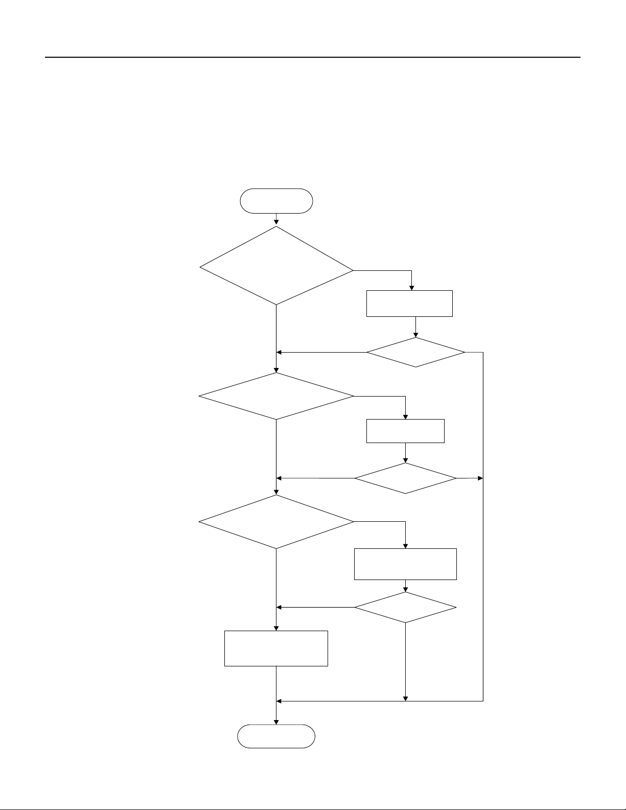
118 PB
TROUBLESHOOTING
Malfunction of Temperature Sensor F1, F2
Indoor unit
(1) Malfunction of Temperature Sensor F1, F2
Main detection points:
● Is the wiring terminal between the temperature sensor and the controller loosened or poorly contacted?
● Is there short circuit due to trip-over of the parts?
● Is the temperature sensor broken?
● Is mainboard broken?
Malfunction diagnosis process:
Start
Is the wiring terminal between the
temperature sensor and the controller
loosened or poorly contacted?
Insert the temperature
sensor tightly
Yes
Yes
Yes
Yes
Yes
Yes
No
No
No
No
No
No
Is malfunction
eliminated
Is malfunction
eliminated
Is malfunction
eliminated
Make the parts upright
Replace it with a
temperature sensor with
the same model
Is there short circuit due to trip-
over of the parts
Is the temperature sensor normal
according to the resistance table?
Replace the mainboard with
the same model.
End

119 PB
TROUBLESHOOTING
9-12k Malfunction of blocked Protection of IDU Fan Motor H6
End
No
Yes
No
Yes
No
Yes
Connect power and restart the unit.
Test whether the voltage between terminal 1 and terminal 2
of motor interface is within 280~310VDC.
Yes
No
No
No
Yes
Then check whether there is voltage
between terminal 2 and terminal 4
of the motor interface.
Yes
Yes
No
Whether the fan blades
can run smoothly?
Turn the fan blades
by hand under
power-off condition
Adjust the motor and blade
assembly so that rotor can run
smoothly.
Under power-off condition,
check whether the wiring terminal
between
indoor fan and main
board is loose.
Turn unit on
to check whether the
malfunction is
eliminated.
Turn unit on
to check whether the
malfunction is
eliminated.
Reinsert the wiring
terminal of indoor fan.
It's the malfunction of main board.
Replace a new main board that is
of the same model.
It's the malfunction of main board.
Replace a new main board that is
of the same model.
It's the malfunction of main board.
Replace a new main board that is
of the same model.
Then check whether the voltage
between terminal 2 and terminal 3
of the motor interface is 15VDC.
It's the malfunction of motor.
Replace a new motor that is
of the same model.
Start
2. Malfunction of Blocked Protection of IDU Fan Motor H6
Main detection points:
● SmoothlyIs the control terminal of PG motor connected tightly?
● SmoothlyIs the feedback interface of PG motor connected tightly?
● The fan motor cant operate?
● The motor is broken?
Malfunction diagnosis process:
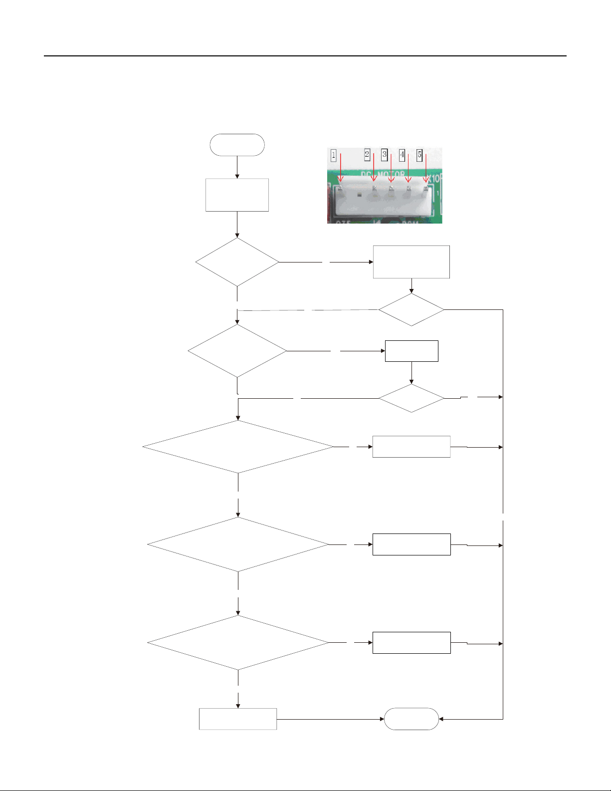
120 PB
TROUBLESHOOTING
18-36k Malfunction of blocked Protection of IDU Fan Motor H6
2.Malfunction of Blocked Protection of IDU Fan Motor H6
End
No
Yes
No
Yes
No
Yes
Yes
Yes
No
No
No
Yes
Yes
No
Turn the fan blades
by hand under
power-off condition
Whether the fan blades
can run smoothly?
Adjust the motor and blade
assembly so that rotor can run
smoothly.
Under power-off condition,
check whether the wiring terminal
board is loose.
between
indoor fan and main
Turn unit on
to check whether the
malfunction is
eliminated.
Turn unit on
to check whether the
malfunction is
eliminated.
Reinsert the wiring
terminal of indoor fan.
It's the malfunction of main board.
Replace a new main board that is
of the same model.
It's the malfunction of main board.
Replace a new main board that is
of the same model.
It's the malfunction of main board.
Replace a new main board that is
of the same model.
Then check whether the voltage
between terminal 2 and terminal 3
of the motor interface is 15VDC.
Connect power and restart the unit.
Test whether the voltage between terminal 1 and terminal 2
of motor interface is within 280~310VDC.
Then check whether there is voltage
between terminal 2 and terminal 4
of the motor interface.
Start
It's the malfunction of motor.
Replace a new motor that is
of the same model.
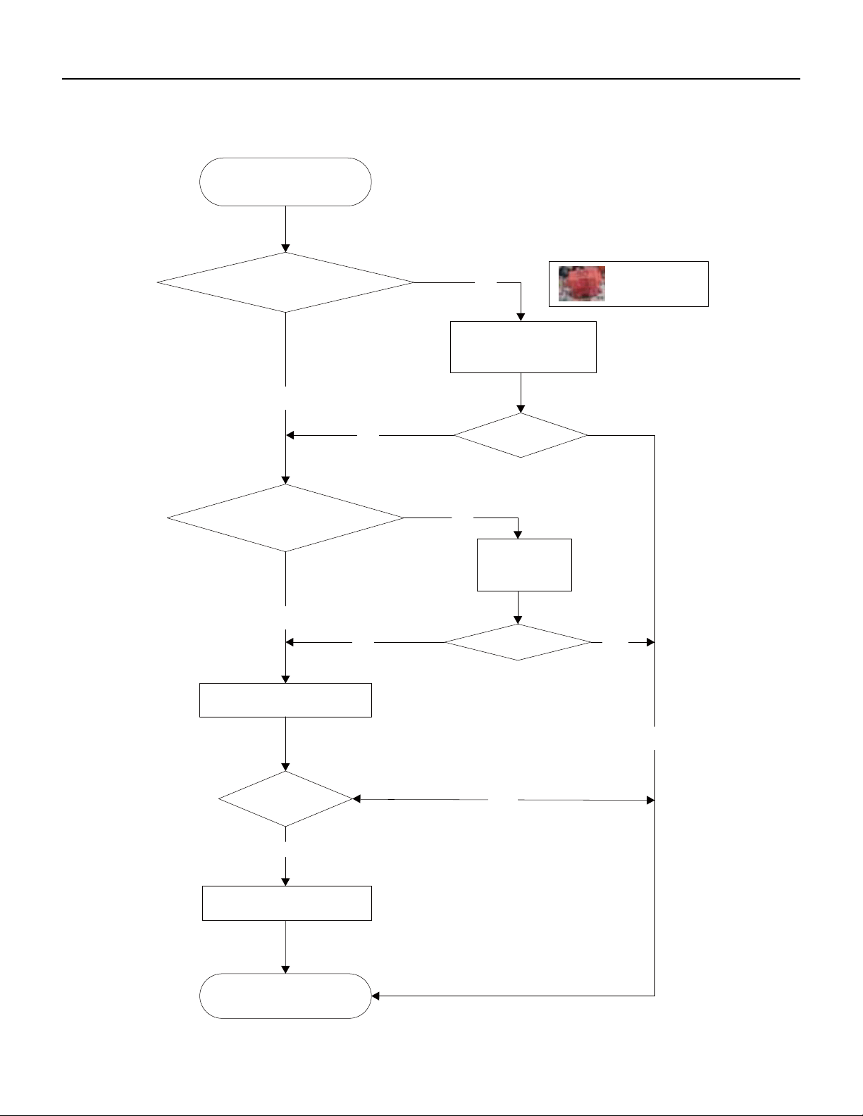
121 PB
TROUBLESHOOTING
Malfunction of Protection of Jumper Cap C5
the jumper cap
Appearance of
Troubleshooting for C5
malfunction
Is there jumper cap on the
mainboard
?
Is
the jumper cap inserted
correctly and
tightly
?
End
yes
yes
Assemble the jumper
cap with the same
model
no
Replace the jumper cap
with the same model
no
eliminated
Is malfunction
yes
Insert the
jumper cap
tightly
no
eliminated
Is malfunction
no
yes
no
I
s malfunction
eliminated
yes
Replace the mainboard
with the same model.
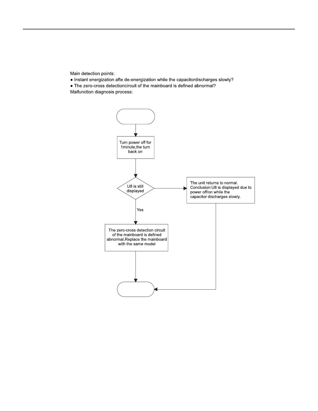
122 PB
TROUBLESHOOTING
Malfunction of IDU Fan Motor U8
Service Manual
No
Start
End
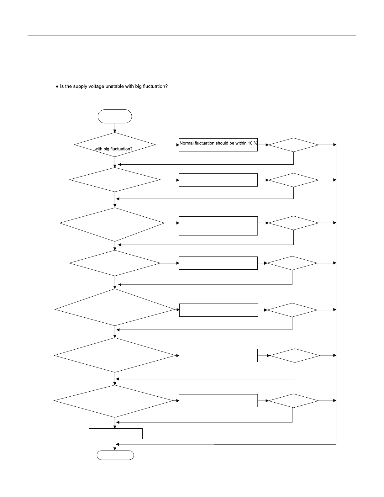
123 PB
TROUBLESHOOTING
Overcurrent Protection E5
Malfunction of Overcurrent Protection E5
Main detection points:
Start
● Is the supply voltage too low with overload?
● Hardware trouble?
Malfunction diagnosis process:
Is the supply voltage unstable
of the rated voltage on the nameplate
Adjust the supply voltage to maintain it
within normal range
Clean the indoor and outdoor heat
exchangers and remove the blockage
of air inlet and outlet
Check the motor and reinstall the
motor to have the fan run normally
Replace the mainboard with the same
model
Flush the heat exchangers with high
pressure nitrogen
Replace the compressor
End
Replace the mainboard
with the same model
Is the supply voltage too low
with overload?
Is the indoor / outdoor
heat exchanger dirty,or are the air inlet
and outlet blocked?
The fan is abnormal? Fan
speed is too low or fan doesn’t rotate
Measure the current of live wire on
the main board with a clamp ampere
meter. Is the current higher than the
value of the overcurrent protection?
Is there blockage inside the system?
(Filth blockage, ice plug, greasy
blockage, the cut off valve hasn’t been
opened completely)
Is malfunction
eliminated
Is the compressor running abnormally?
Is there abnormal sound or oil leakage;
Is the temperature of the shell too high,
etc.?
Is malfunction
eliminated
Is malfunction
eliminated
Is malfunction
eliminated
Is malfunction
eliminated
Is malfunction
eliminated
Is malfunction
eliminated
Yes Yes
Yes
Yes
Yes
Yes
Yes
Yes
Yes
Yes
Yes
Yes
Yes
Yes
No No
No
No
No
No
No No
No
No
No
No
No
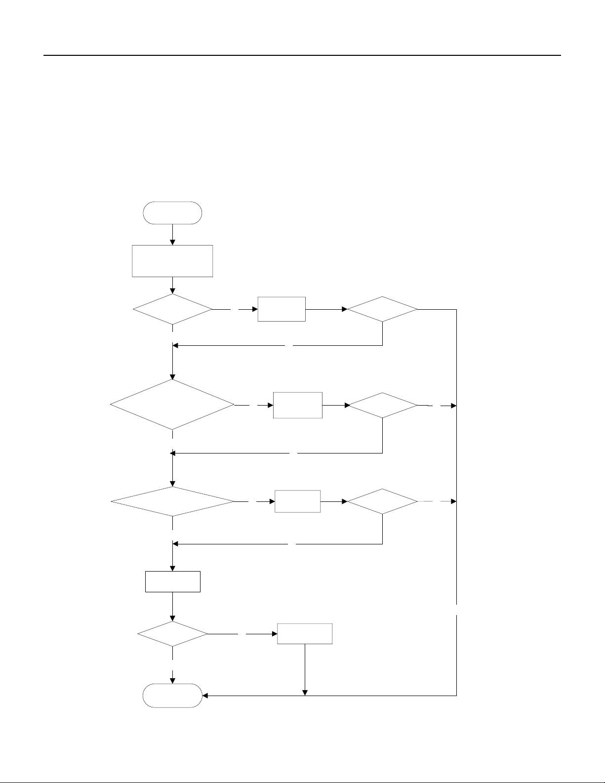
124 PB
TROUBLESHOOTING
Malfunction of Communication E6
Malfunction of communication E6
Main detection points:
● Check if the connection wire and the built-in wiring of indoor and outdoor unit are connected well and without damage;
● If the communication circuit of indoor mainboard is damaged? If the communication circuit of outdoor mainboard (AP1) is
damaged?
Malfunction diagnosis process:
Start
Cut off power supply. Check if
connection line of IDU and ODU
and the wire inside electric box
are correctly connected.
Correct connection?
IDU matches with that of ODU?
Communication cord is damaged?
Main board matches
with display board? Main board of
main board
Replace IDU's
Malfunction eliminated?
End
Connect the line
according to
Match correctly
wiring diagram.
according to product
specification
communication
Replace
cord
Replace ODU's
Malfunction eliminated?
main board.
Malfunction eliminated?
Malfunction eliminated?
yes
yes
yes
yes
yes
yes
no
yes
no
no
no
no
no
no
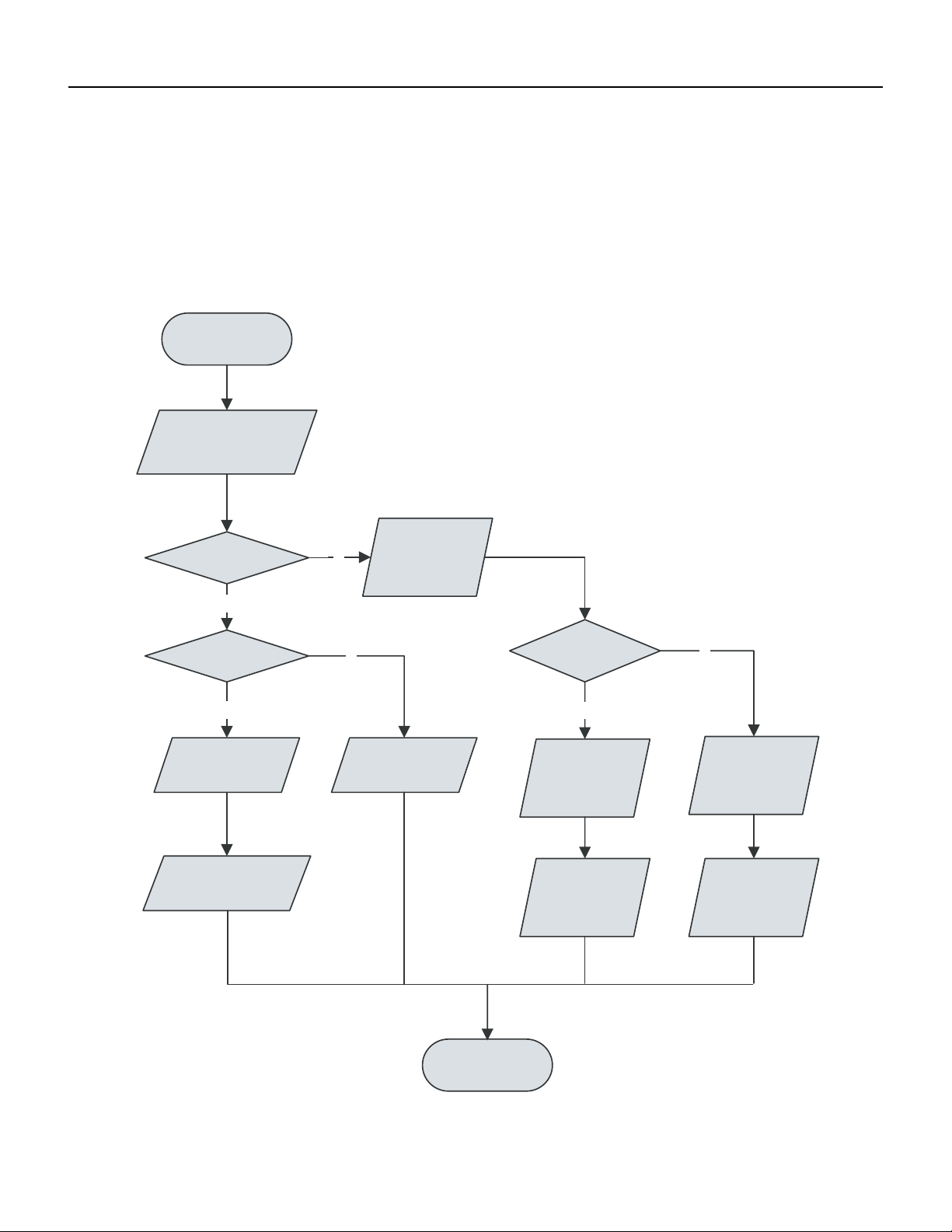
125 PB
TROUBLESHOOTING
Malfunction of Power Supply from Indoor to Outdoor Unit
Y
Y
N
N
Y
N
Energize the unit
and wait for 3min
Voltage > 200V?
Measure voltage between
N 1and 3 of indoor
wiring block
Measure voltage
between L and N
of outdoor wiring
block
Normal wiring?
Voltage > 200V?
Indoor main board error
Adjust wiring
Outdoor electric
box error
indoor and outdoor
wiring error
Replace main board
of indoor unit
Replace outdoor
electric box
Replace indoor
and outdoor wiring
Remove malfunction
Inspect the power supply plug seat wit hAC voltage guage to check if voltage between L and N is within 200VAC‑240 VAC.
Check with AC voltage gauge if the voltage between N1 and 3 of indoor wiring block is within 200 VAC‑240AC
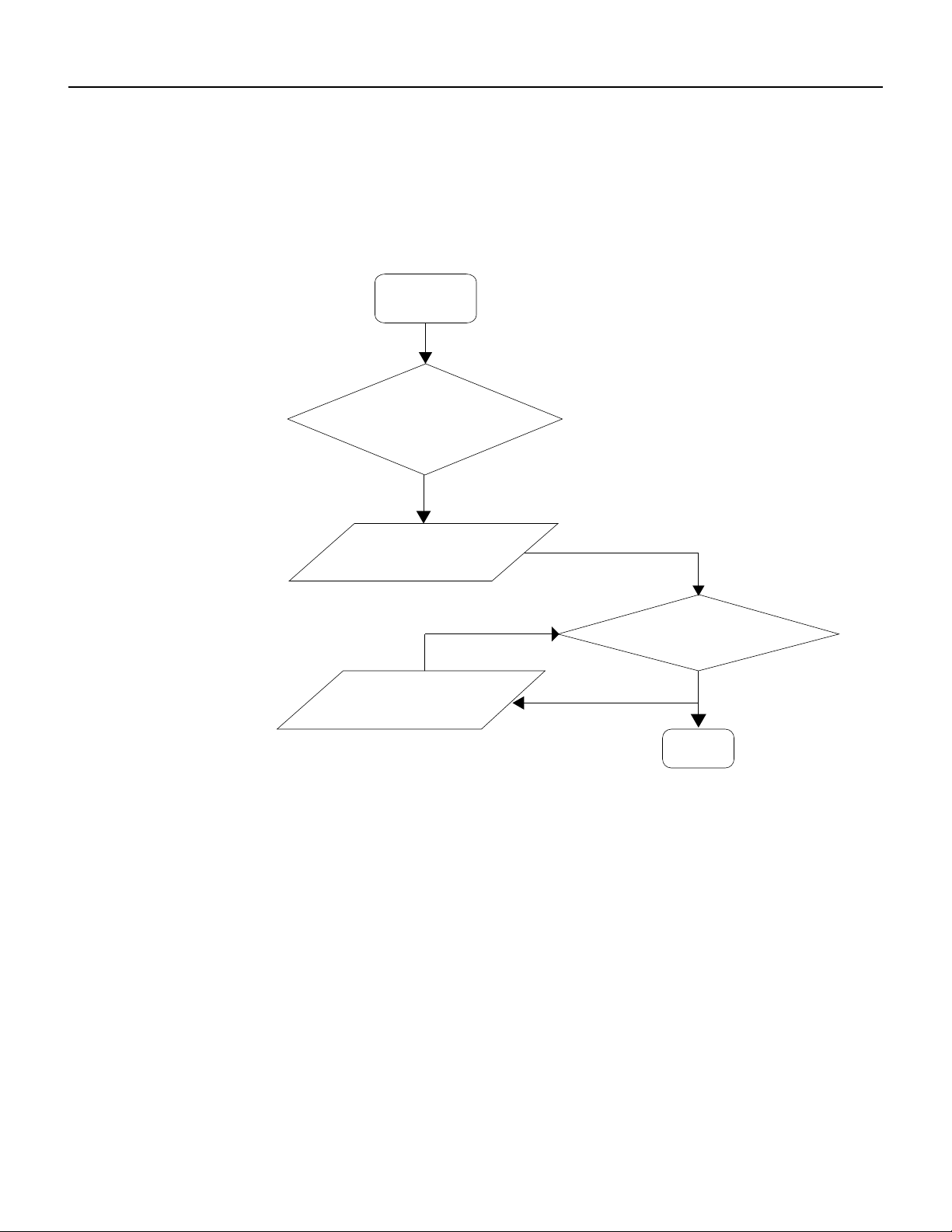
126 PB
TROUBLESHOOTING
Malfunction of Detecting Plate (WIFI) JF
Malfunction of detecting plate(WIFI) JF
Start
Is malfunction
eliminated
The end
check if the connection wire
are correctly connected
Replace the
detecting
plate
with the same model
Replace the mainboard
with the same model
Yes
Yes
No
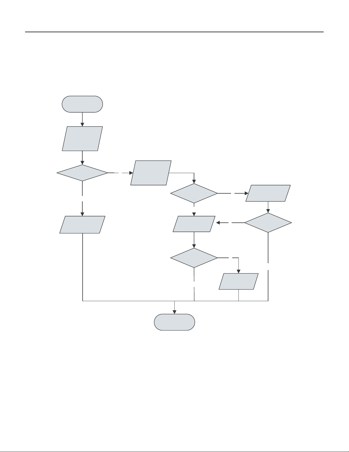
127 PB
TROUBLESHOOTING
Indoor fan does not rotate and there is no Feedback
Is the control panel reliably connected with the motor? Is it loose? Is the connecting sequence correct?
Is the input voltage within the normal range (measure the voltage between L and N of the wiring block XT with AC voltage gauge.)?
Y
Y
Y
N
N
N
Y
N
unit and start it
Energize the
Voltage between
L and N of
indoor wiring
block
Voltage > 200V?
Check power
supply
connecting
Check the
connecting
terminal
Reliable
connection
state of the
unit
Replace main
board of indoor
Remove the
Adjust
connecting
error?
state
remove the
error?
Replace motor
Finish
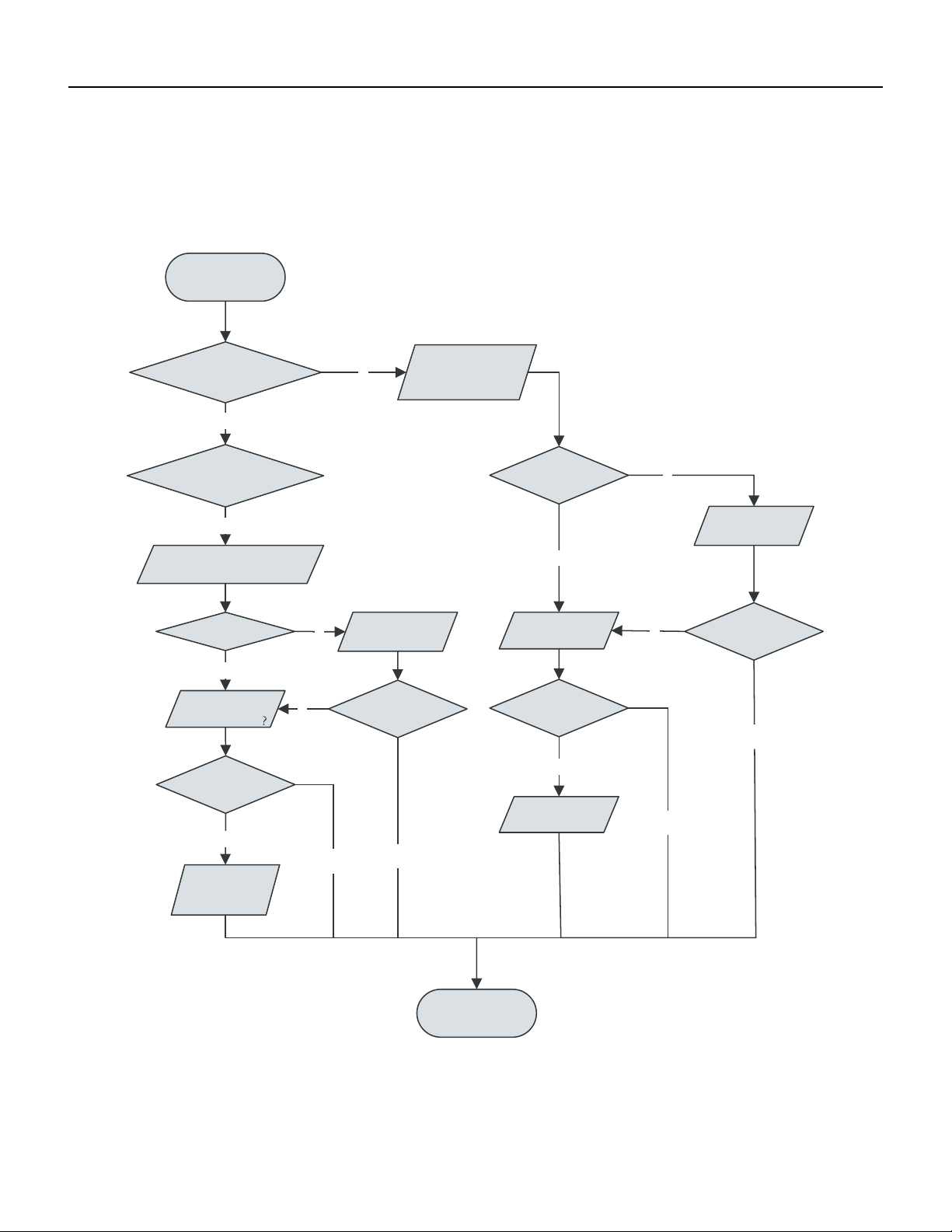
128 PB
TROUBLESHOOTING
Temperature sensor malfunction
Is outdoor ambient temperature within the normal range?
Is indoor and outdoor fan running normally?
Is the radiating environment inside and outside the unit good enough?
Y
Y
N
N
Y
N
N
Y
Y
N
N
N
Y
Y
Y
it
unit and start
Energize the
Indoor unit
Indoor unit
display F1/F2
display F4/F5
Reliable
connected?
Replace
Check connecting state of
outdoor temperature sensor
Tesmepnesroar
ture Sensor
Remove error?
Replace parts
electric box
of outdoor
Check connecting
temperature
state of indoor
sensor
Adjust
Remove error?
connecting state
reliable
connected?
Replace
temperature
Remove error?
sensor
Replace main
Adjust
boarudn iotf in door
connecting state
Finish
Remove error?
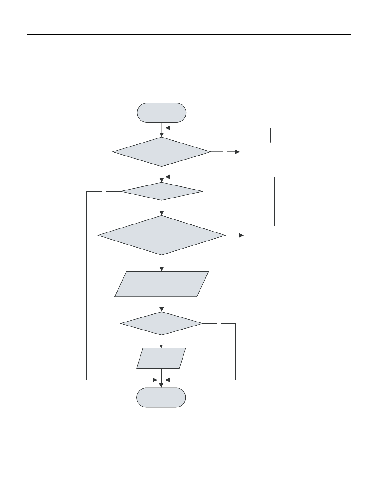
129 PB
TROUBLESHOOTING
Malfunction diagnosis of startup failure
Is wiring of compressor correct.
Is the stop time of compressor enough?
Is compressor damaged?
Y
N
Y
N
N
Y
Y
N
Energize the
unit and start it
Is the stop time
of compressor more
than 3min
Start it 3 min later
Startup failure?
Is compressor wire connected correctly?
Connect it according
to wiring diagram
Replace parts of outdoor
electric box
Remove the error?
Replace
compressor
nish
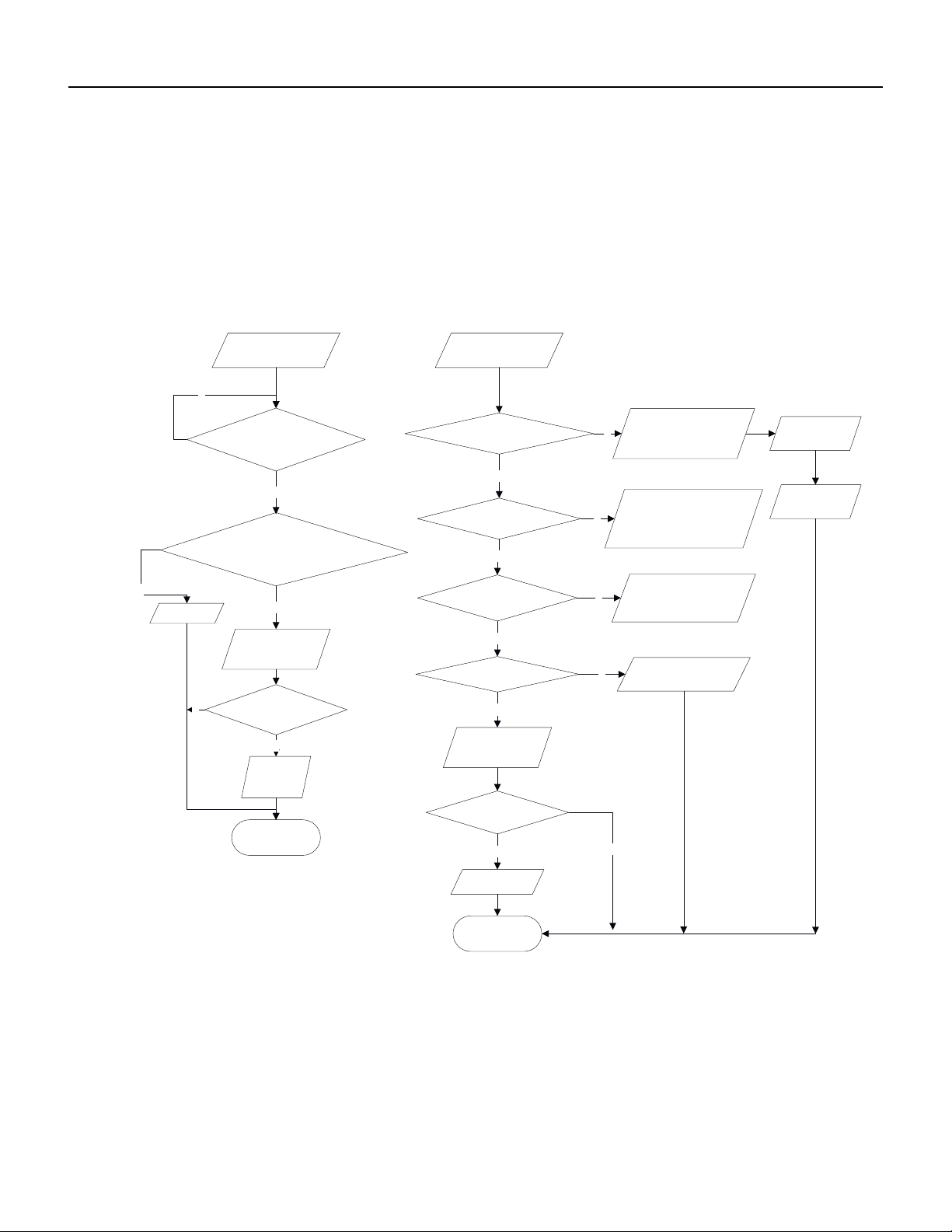
130 PB
TROUBLESHOOTING
Diagnosis of losing synchronism for compressor
(AP1 below is control board of outdoor unit)
● If the system pressure is over-high?
● If the work voltage is over-low?
Malfunction diagnosis process:
If the compressor wire COMP(UVW) is well
connected, the connection sequence
forwards to clockwise direction?
Check if the fan
terminal OFAN is
connected well
Replace
compressor
If the outdoor fan works
normally?
3min
If the stop time of
compressor is more than
Synchronism after
and start it
energize the unit
Connect
wire well
Synchronism
occurred during
operation
Replace
control board
AP1
If the radiating of unit is
well?
Remove
malfunction?
Replace fan
capacitor C1
Improve the radiating
of unit (clean heat
exchanger and
increase ventilation)
Replace
outdoor fan
Y
N
N
Y
Y
N
Replace
control board
AP1
Remove
malfunction?
Replace
compressor
Y
N
N
Y
Start to run until the
power resume normal
voltage
N
Charge the
refrigerant with
service manual
Y
N
If the input voltage of unit
is normal?
Y
If the refrigerant is too
much?
N
Y
End
End
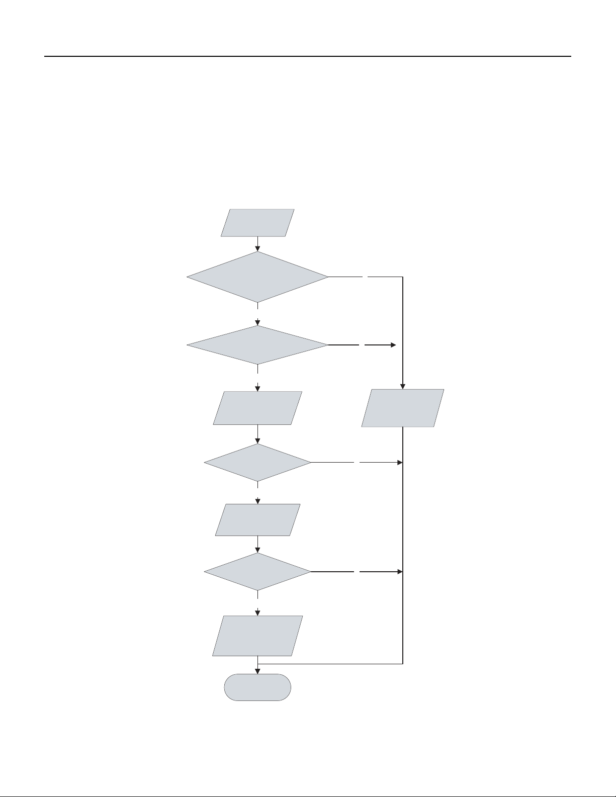
131 PB
TROUBLESHOOTING
9-12k, 36k Diagnosis of overload and discharge malfunction
Is electric expansion valve well connected? Is it damaged?
Is refrigerant leaked?
Is overload wire connection normal?
Are resistances between the first four pins close to the terminal hole and the 5th pin almost the same.? They should be less than 100
ohm.
N
N
N
Y
Y
Y
Y
N
20min after
de-energization
of complete unit
expansion valve
Is electric
Is overload wire
well connected?
expansion valve
reliably connected?
Replace electric
Remove
Replace parts
malfunction?
electric box
of outdoor
Refrigerant leakage,
recharge the
Remove malfunction?
Adjust
refrigerant
Finish
connecting wire
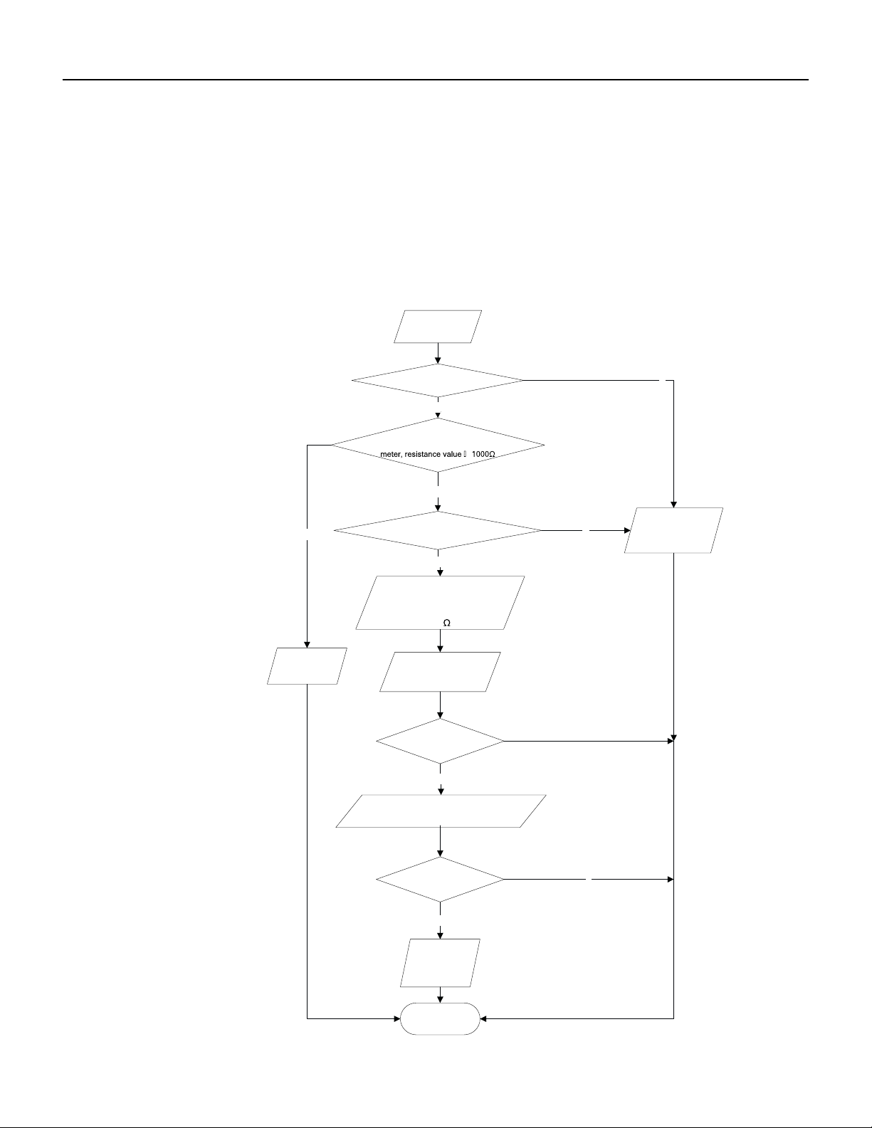
132 PB
TROUBLESHOOTING
18-24k Diagnosis of overload and discharge malfunction
Diagnosis for overload and discharge malfunction (AP1 below is control board of outdoor unit)
Main detection point:
Malfunction diagnosis process:
● If the electron expansion valve is connected well? Is the expansion valve damaged?
● If the refrigerant is leakage?
● If the overload protector is damaged?
Connect wire
well with wiring
diagram
Replace EKV
coil of electron
expansion valve
Remove
malfunction?
After the unit
for 20min
de-energized
Remove
malfunction?
The resistance value of
firs t 4 l ea d fo ot an d th e
fif th lead foot is similar,
less than 100
Y
If the wiring terminal FA of electron
expansion is well connected?
Y
N
N
N
If the overload protector SAT
is well connected?
N
Under ambient temperature, test the
resistance of overload protector with ohmic
Y
Replace
overload
protector SAT
N
Y
Replace
Check refrigerant, if there is
leakage, please refer to
specification
control board
AP1
End
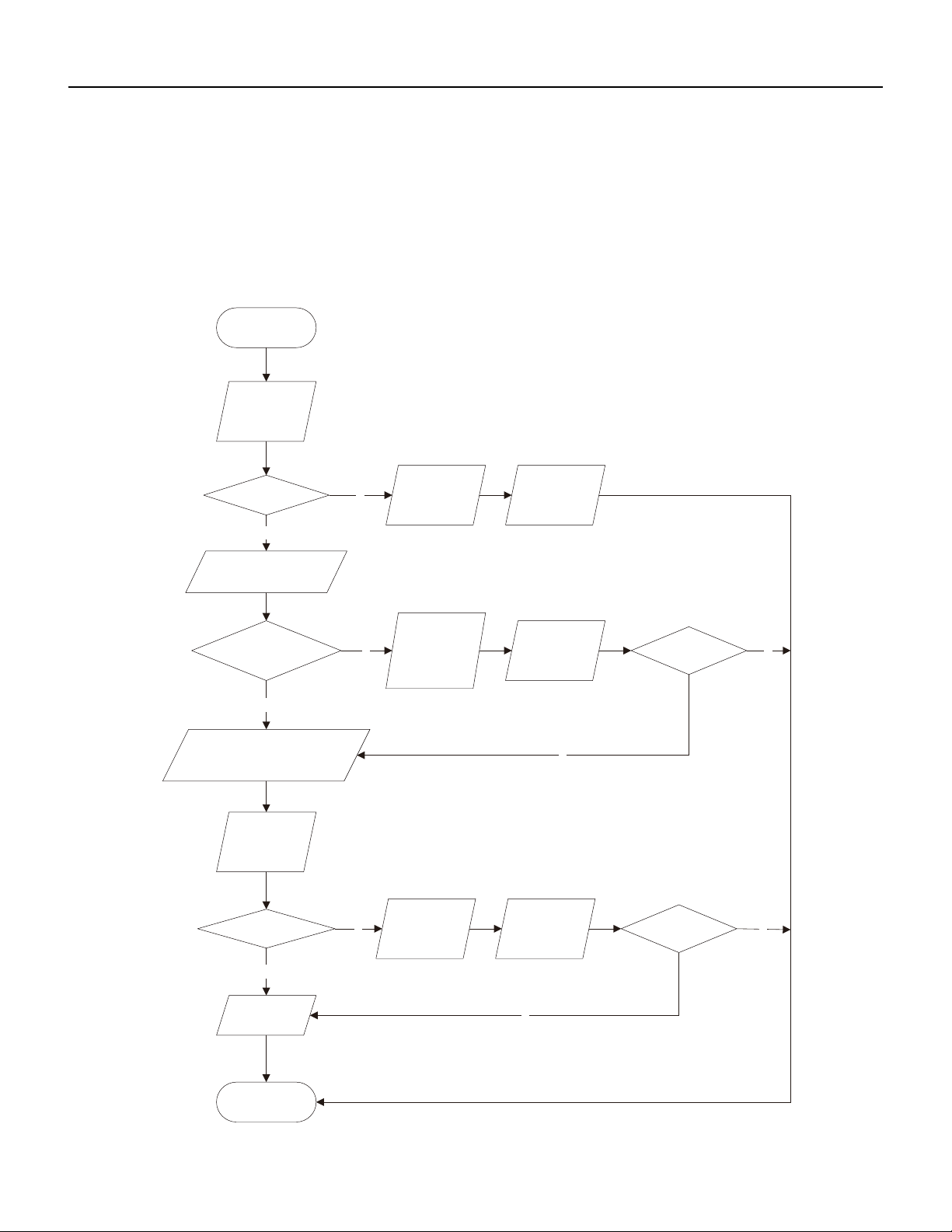
133 PB
TROUBLESHOOTING
Capacity Charging malfunction - Outdoor unit
1) Capacitor charge fault (Fault with outdoor unit) (AP1 below refers to the outdoor control panel)
Main Check Points:
Use AC voltmeter to check if the voltage between terminal L and N on the wiring board is within 210VAC~240VAC.
If the reactor (L) is correctly connected? If the connection is loose or fallen? If the reactor (L) is damaged?
N
Y
N
Y
N
Y
N
Y
N
Y
Turn on the unit
and wait 1 minute
Use DC voltmeter
to measure the
voltage on the two
ends of electrolytic
capacitor
Fault with the voltage
Voltage higher than 200V?
testing circuit on
control panel AP1
Replace the control
panel AP1
Voltage within
Shut down the power
and repair the power
210VAC~250VAC?
supply to restore the
Measure the AC voltage between
terminal
L andN on wiring board
XT(power supply)
range
210VAC~250VAC
power on and
restart the unit
If the fault is
eliminated?
Check the
connection of reactor
Shut down the power and wait 20 mi
nutes;or
use DC voltmeter to measure the voltage
on the two ends of capacitor , until
the voltage is lower than 20V
(L in the Electrical
Wiring Diagram)
If the wiring of
Connect the reactor
reactor L
is normal?
Laccording to Elec-
trical Wiring Diagr-
am correctly
Re-energize and
turn on the unit
If the fault is
eliminated?
End
Replace the control
panel AP1
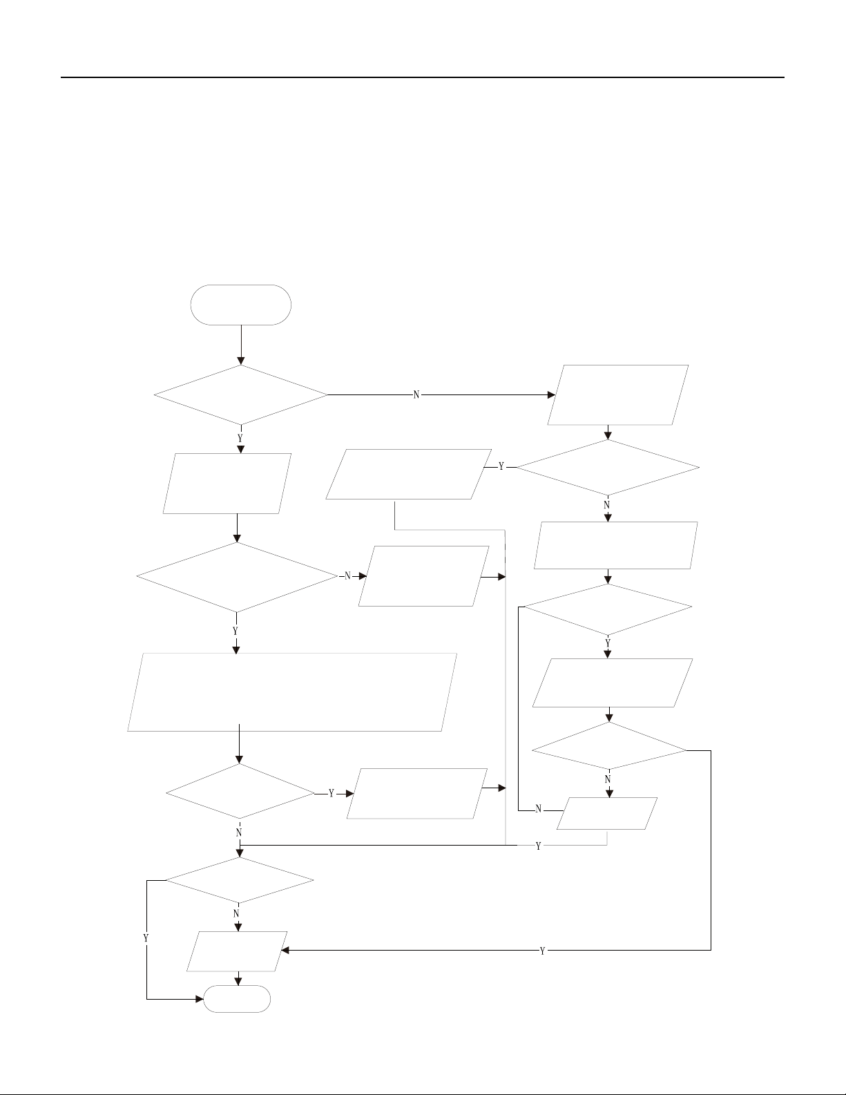
134 PB
TROUBLESHOOTING
9-24k PM protection, phase current overcurrent
(the control board as below indicates the control board of outdoor unit) H5/P5
Mainly detect:
(1) Compressor COMP terminal (2) voltage of power supply (3) compressor
(4) Refrigerant-charging volume (5) air outlet and air inlet of outdoor/indoor unit
Troubleshooting:
Turn on the unit
after energization
Whether IPM
protection occurs after the unit has
operated for a while?
Measure the voltage
between terminal L
and terminal N with
AC volmeter
Whether
the voltage between
terminal L and terminal N of XT is
within 210AVC~
250VAC?
1. Whether the heat exchangers of indoor unit and outdoor unit are
dirty? Whether the radiation is affected because the unit is
covered by the objects?
2. When indoor fan and outdoor unit are operate normally?
3. Whether the system pressure is too high?
4. Whether the pressure is because there's too much refrigerant?
Check the power
supply voltage and
make the power voltage
resume to the range
of 210VAC~250VAC
Correctly connect the wires of
compressor according to the
electric wiring diagram, and
then turn on the unit
Check whether wires
of compressor (UVW) are connected
correctly
Check the connection
between the control board
and the compressor by
referring to the electric
wiring diagram
Measure the resistance value
among three terminals (UVW)
of compressor with a resistance
measuring meter.
Whether the
resistance value of three terminals
are almost the same.
Replace the
compressor
Whether the unit
can operate normally?
Whether there's
abnormal phenomenons
described as above?
End
Replace control
board
Measure the resistance
between three terminals (UVW)
of compressor and the copper pipe
with resistance measuring meter
Whether the
resistance value is more than
500ohm?
Correct it one by one
according to the Service
Manual, and then turn on
the unit.
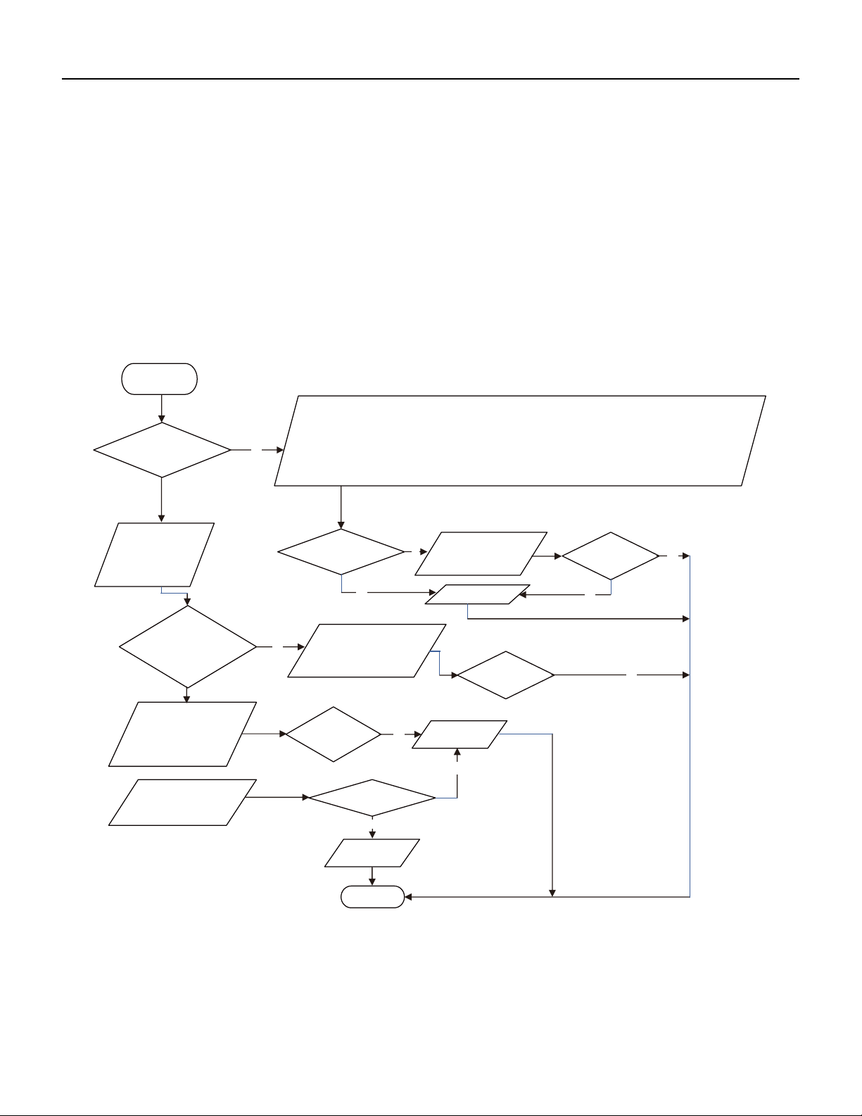
135 PB
TROUBLESHOOTING
36k IPM Protection, Out-of-Step Fault, Compressor Phase Overcurrent
If the connection between control panel AP1 and compressor COMP is secure? If loose? If the connection is in correct order?
If the voltage input of the machine is within normal range? (Use AC voltmeter to measure the voltage between terminal L and N on the wiring board
XT)
If the compressor coil resistance is normal? If the insulation of compressor coil against the copper tube is in good condition?If the
working load of the machine are too high? If the radiation is good?
If the charge volume of refrigerant is correct?
(AP1 below refers to the outdoor control panel)
Energize and
switch on
IPM protection
occurs after the
machine has run for
Please confirm:
a
period of time?
1. If the indoor and outdoor heat exchangers are dirty? If they are obstructed by other objects which affect the
heat exchange of indoor and outdoor unit.
2. If the indoor and outdoor fans are working normally?
3. If the environment temperature is too high, resulting in that the system pressure is too high and exceeds the
permissible range?
4. If the charge volume of refrigerant is too much, resulting in that the system pressure is too high?
5. Other conditions resulting in that the system pressure becomes too high.
then energize and start
the unit.
If there is any
abnormality
Take corrective actions
according to Technical
Service Manual, and
described above?
Replace the
If the connection
control panel AP1
between AP1 and
COMP is unsecure
or the connection
order is wrong?
Connect the control panel
AP1 and compressor
COMP correctly according
to the Electrical Wiring
Diagram. Then, energize
and start the unit.
Service Manual.
compressor resistance on
If the
resistance is
normal?
Use ohmmeter to
measure the resistance
between the three
terminals on compressor
COMP, and compare the
measurements with the
Use ohmmeter to
measure the resistance
between the two
terminals of compressor
COMP and copper tube.
Replace the
compressor
COMP
Resistance higher
than 500MΩ?
Replace the
AP1
control panel
END
If the unit can
work normally?
Y
Y
N
N
If the unit can
normally?
work
Y
Y
Y
N
Y
N
Refer to the
Electrical Wiring
Diagram and check
if the connection
between AP1 and
COMP is loose and if
the connection order
is correct.
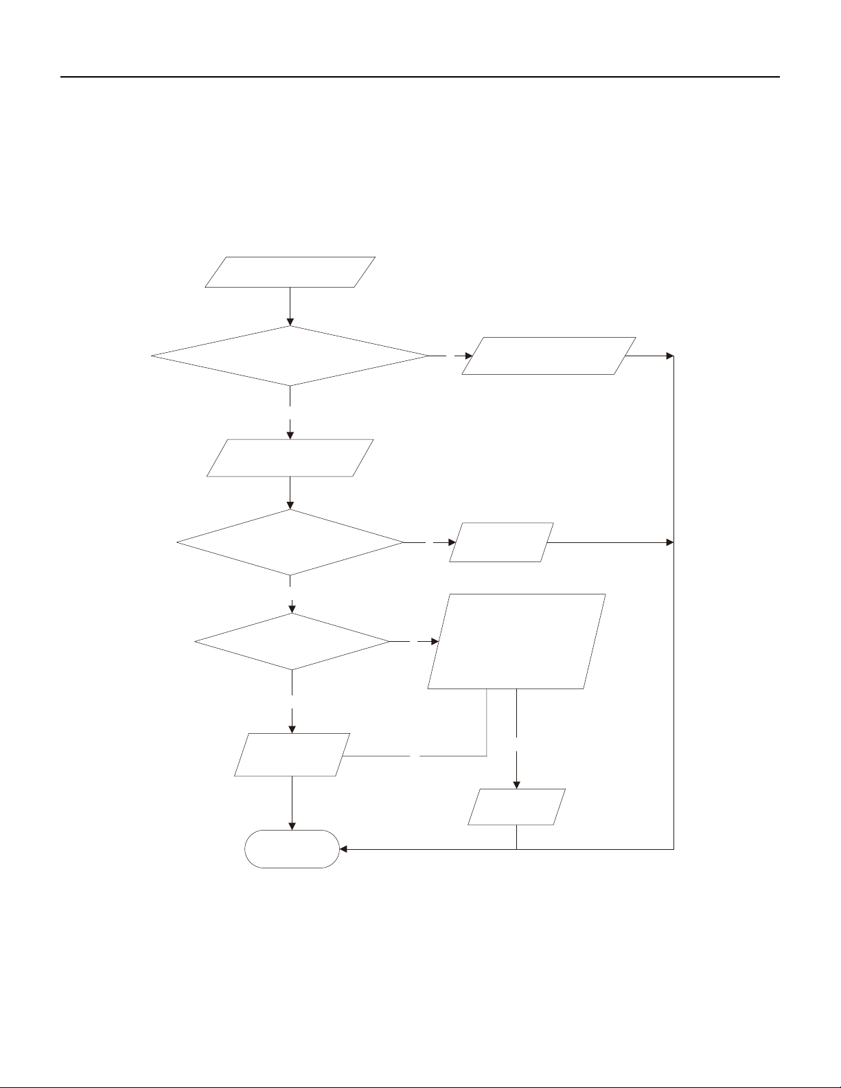
136 PB
TROUBLESHOOTING
High temperature and Overload Protection Diagnosis
Is outdoor ambient temperature in normal range?
Are the outdoor and indoor fans operating normally?
Is the heat dissipation environment inside and outside the unit is good?
(AP1 below refers to the outdoor control panel)
End
Y
Y
N
Y
N
N
Y
N
Overheat and high
temperature protection
Is outdoor ambient temperature higher than 127.4˚F
20 minutes after the complete
unit is powered off.
Is heat dissipation of the indoor unit
and outdoor unit abnormal?
Improve the heat
Normal protection, please operate
it after the outdoor ambient temp-
erature is normalized.
dissipation environ-
ment of the unit
Does the outdoor fan work normally?
Replace the
control panel
AP1
Replace the
outdoor fan
1. Check if the fan terminal OFAN
is connected correctly
2. Unplug the fan hub , ohms table Fan
measuring between any two end
terminals of the resistor , resistance is less
than 1KOhm
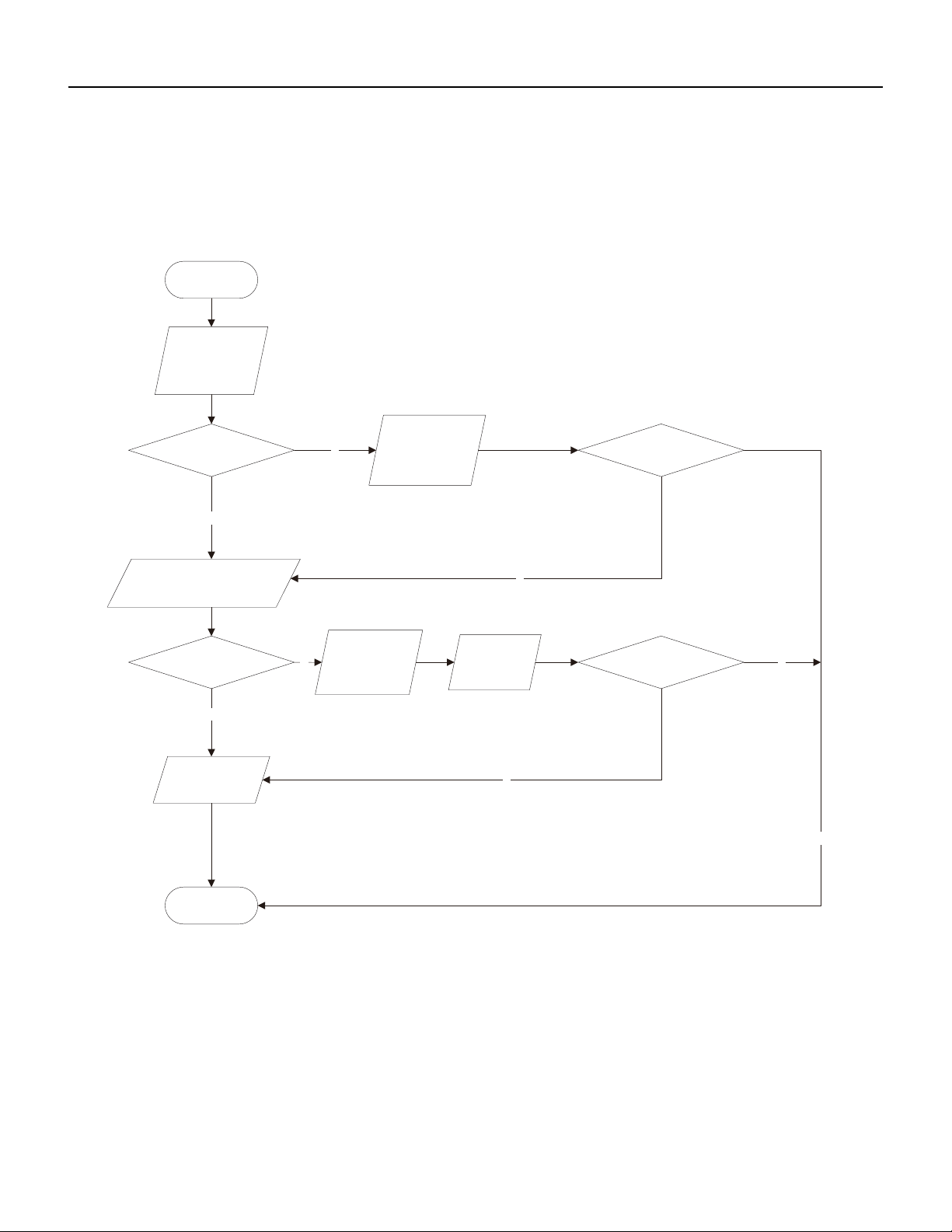
137 PB
TROUBLESHOOTING
PFC (Correction Power Factor) Outdor Unit Malfuction
AP1 hereinafter refers to the control board of the outdoor unit
Check if the reactor (L) of the outdoor unit and the PFC capacitor are broken
Y
N
N
N
N
Y
Y
Start
Check wiring of the
reactor (L) of the
PFC capacitor
outdoor unit and the
Whether there is any
damage or
short-circuit?
If the fault is eliminated?
Replace it as per the
wiring diagram and
reconnect the wires
Whether there is any damage
or short-circuit?
Replace the reactor
Disconnect the terminals for the
reactor and measure the resistance
between the two terminals of the
reactor by an ohm gauge
Restart the unit
If the fault is eliminated?
Replace the control
panel AP1
End
Y
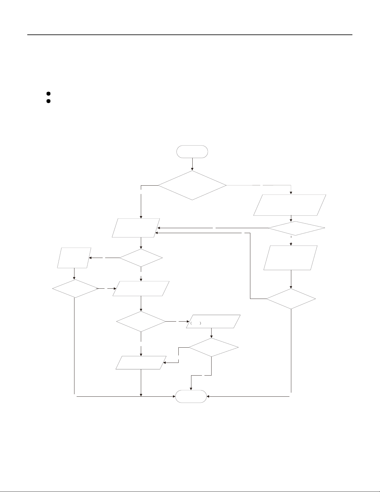
138 PB
TROUBLESHOOTING
Communication malfunction: (following AP1 for outdoor unit control board)
Fault diagnosis process:
Y
N
Y
N
N
Y
N
(8) Communication malfunction: (following AP1 for outdoor unit control board)
Mainly detect:
Is there any damage for the indoor unit mainboard communication circuit? Is communication circuit damaged?
Detect the indoor and outdoor units connection wire and indoor and outdoor units inside wiring is connect well or not, if is
there any damage?
N
Y
N
Y
N
Y
Y
Start
The AP1 voltage
detection circuit
Did the equipment operate
normally before the failure
occurs?
is at fault
units
Are wires broken?
Check wiring inside of
the indoor and outdoor
If the fault is eliminated?
Check the communication
circuit of the outdoor unit
The communication
circuit is abnormal
End
If the fault is eliminated?
Replace the main board
of
the indoor unit
If the fault is eliminated?
Replace the main board
AP1 of the outdoor unit
Is the connection right?
wiring diagram
Check the wiring of the indoor and
outdoor units with reference to the
Correctly connect the
corresponding wires for
the indoor and outdoor
units with reference to
the wiring diagram
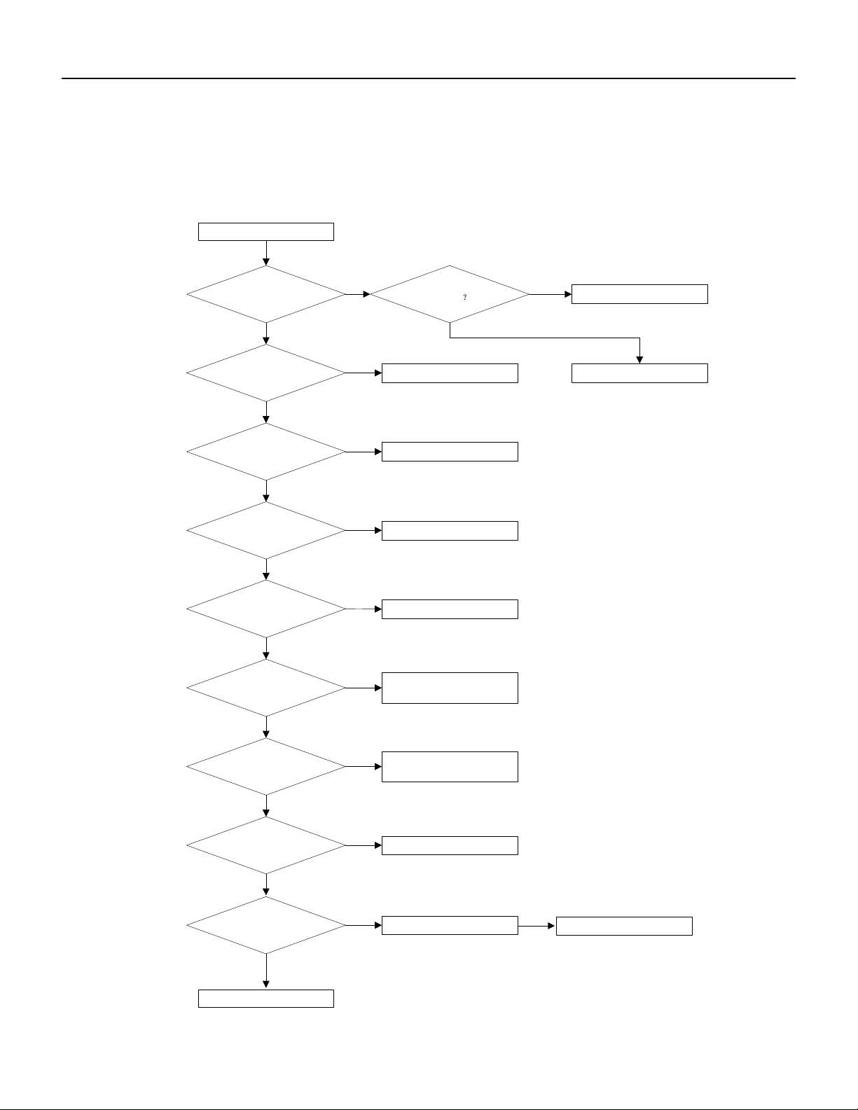
139 PB
TROUBLESHOOTING
High-pressure Protection
High-pressure Protection
High-pressure protection
Use pressure gauge to
measure if the pressure is
really high?
Check if the operation mode of
indoor unit is set properly?
Check if the gas valve and
liquid valve are fully open?
Check if the front panel of
outdoor unit is covered tightly?
Check if the air inlet and outlet of
the indoor and outdoor
exchanger is smooth ?
Check if the indoor and
outdoor fans operate normally?
Check if the indoor swing
louver is fully open ?
Check if the capacity output of
outdoor unit is equal to the
capacity demand of indoor units?
Clean the fins
The system pipe is blocked
Check if the indoor / outdoor
filters or radiating fins are dirty or
blocked ?
Refer to the dial -up of indoor
and outdoor unit
Measure the swing motor and
signal input
Measure the fan motor and
signal input
Remove the obstructions
Cover up the front panel
properly
Fully open the valve
Set the correct operation
mode
Measure if the pressure switch
is normal
Replace the pressure switch
no
no
no
no
no
no
no
no
no yes
yes
yes
yes
yes
yes
yes
yes
yes
no
no
Replace the mainboard of
outdoor unit
Replace the blocked parts or
pipe
140 PB
TROUBLESHOOTING
Troubleshooting for Malfunction without Active Error Code
Possible Causes Discriminating Method (Air conditioner Status) Troubleshooting
Air Conditioner will not start up
No power supply, or poor connection for power
plug
After energization, operation indicator isn’t
bright and the buzzer can't give out sound
Confirm whether it's due to power failure.
If yes, wait for power recovery. If not, check
power supply circuit and make sure the power
plug is connected well.
"Wrong wire connection between indoor unit
and outdoor unit,
or poor connection for wiring terminals"
Under normal power supply circumstances,
operation indicator isn't bright after energiza‑
tion
Check the circuit according to circuit diagram
and connect wires correctly. Make sure all wir‑
ing terminals are connected firmly
Electric leakage for air conditioner After energization, room circuit breaker trips
off at once
"Make sure the air conditioner is grounded
reliably
Make sure wires of air conditioner is connected
correctly
Check the wiring inside air conditioner. Check
whether the insulation layer of power cord is
damaged; if yes, place the power cord."
Model selection for air switch is improper After energization, air switch trips off Select proper air switch
Malfunction of remote controller After energization, operation indicator is bright,
while no display on remote controller or but‑
tons have no action.
Replace batteries for remote controller Repair
or replace remote controller
Poor Cooling (Heating) for Air Conditioner
Set temperature is improper Observe the set temperature on remote
controller
Adjust the set temperature
Rotation speed of the IDU fan motor is set too
low
Small wind blow Set the fan speed at high or medium
Filter of indoor unit is blocked Check the filter to see it's blocked Clean the filter
Installation position for indoor unit and outdoor
unit is improper
Check whether the installation postion is
proper according to installation requirement
for air conditioner
Adjust the installation position, and install the
rainproof and sunproof for outdoor unit
Refrigerant is leaking Discharged air temperature during cooling is
higher than normal discharged wind tem‑
perature; Discharged air temperature during
heating is lower than normal discharged wind
temperature; Unit's pressure is much lower
than regulated range
Find out the leakage causes and deal with it.
Add refrigerant.
Malfunction of 4‑way valve Blow cold wind during heating Replace the 4‑way valve
Malfunction of capillary Discharged air temperature during cooling is
higher than normal discharged wind tem‑
perature; Discharged air temperature during
heating is lower than normal discharged wind
temperature; Unit't pressure is much lower
than regulated range. If refrigerant isn’t leak‑
ing, part of capillary is blocked
Replace the capillary
Flow volume of valve is insufficient The pressure of valves is much lower than that
stated in the specification
Open the valve completely
Malfunction of horizontal louver Horizontal louver can’t swing Refer to point 3 of maintenance method for
details
141 PB
Possible Causes Discriminating Method (Air conditioner Status) Troubleshooting
Malfunction of the IDU fan motor The IDU fan motor can’t operate Refer to troubleshooting for H6 for mainte‑
nance method in details
Malfunction of the ODU fan motor The ODU fan motor can't operate Refer to point 4 of maintenance method for
details
Malfunction of compressor Compressor can't operate Refer to point 5 of maintenance method for
details
Horizontal Louver Will Not Swing
Wrong wire connection, or poor connection Check the wiring status according to circuit
diagram
Connect wires according to wiring diagram to
make sure all wiring terminals are connected
firmly
Stepping motor is damaged Stepping motor can't operate Repair or replace stepping motor
Main board is damaged Others are all normal, while horizontal louver
can't operate
Replace the main board with the same model
ODU Fan Moto Can’t Operate
Wrong wire connection, or poor connection Check the wiring status according to circuit
diagram
"Connect wires according to wiring diagram to
make sure all wiring terminals are connected
firmly"
Capacity of the ODU fan motor is damaged "Measure the capacity of fan capacitor with
an universal meter and find that the capacity
is out of the deviation range indicated on the
nameplate of
fan capacitor."
Replace the capacity of fan
"Power voltage is a little low or
high"
"Use universal meter to measure the power
supply
voltage. The voltage is a little high or low"
Suggest to equip with voltage regulator
Motor of outdoor unit is damaged "When unit is on, cooling/heating performance
is bad and ODU compressor generates a lot of
noise and heat."
Change compressor oil and refrigerant. If no
better, replace the compressor with a new one
Compressor Can’t operate
Wrong wire connection, or poor connection Check the wiring status according to circuit
diagram
"Connect wires according to wiring diagram to
make sure all wiring terminals are connected
firmly"
Capacity of compressor is damaged "Measure the capacity of fan capacitor with
an universal meter and find that the capacity
is out of the deviation range indicated on the
nameplate of
fan capacitor."
Replace the compressor capacitor
"Power voltage is a little low or
high"
"Use universal meter to measure the power
supply
voltage. The voltage is a little high or low"
Suggest to equip with voltage regulator
Coil of compressor is burnt out "Use universal meter to measure the resis‑
tance
between compressor terminals and it's 0"
Repair or replace compressor
TROUBLESHOOTING
Troubleshooting for Malfunction without Active Error Code
142 PB
Possible Causes Discriminating Method (Air conditioner Status) Troubleshooting
Cylinder of compressor is blocked Compressor can't operate Repair or replace compressor
Air Conditioner is Leaking
Drain pipe is blocked Water leaking from indoor unit "Eliminate the foreign objects inside the
drain
pipe"
Drain pipe is broken Water leaking from drain pipe Replace drain pipe
Wrapping is not tight "Water leaking from the pipe connection place
of
indoor unit"
Wrap it again and bundle it tightly
Abnormal Sound and vibration
"When turn on or turn off the unit, the panel
and other parts will expand and there's abnor‑
mal
sound"
There's the sound of "PAPA" Normal phenomenon. Abnormal sound will
disappear after a few minutes.
"When turn on or turn off the unit, there's
abnormal sound due
to flow of refrigerant inside air
conditioner"
Water‑running sound can be heard Normal phenomenon. Abnormal sound will
disappear after a few minutes.
"Foreign objects inside the indoor
unit or there're parts touching together inside
the indoor unit"
There's abnormal sound fro indoor unit "Remove foreign objects. Adjust all parts'
position of indoor unit, tighten screws and stick
damping plaster between connected parts"
"Foreign objects inside the outdoor unit or
there're parts touching
together inside the outdoor unit"
There's abnormal sound fro outdoor unit "Remove foreign objects. Adjust all parts' posi‑
tion of outdoor unit, tighten screws and
stick damping plaster between connected
parts"
"Short circuit inside the magnetic
coil"
"During heating, the way valve has abnormal
electromagnetic sound"
Replace magnetic coil
Abnormal shake of compressor Outdoor unit gives out abnormal sound "Adjust the support foot mat of compressor,
tighten the bolts"
Abnormal sound inside the compressor Abnormal sound inside the compressor "If add too much refrigerant during mainte‑
nance, please reduce refrigerant properly.
Replace
ircumstances."
TROUBLESHOOTING
Troubleshooting for Malfunction without Active Error Code
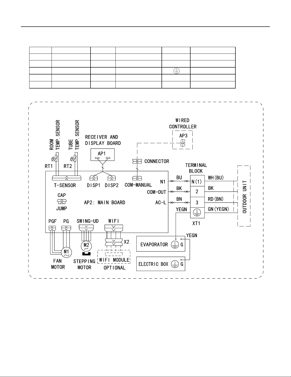
143 PB
WIRING DIAGRAMS
Figure 801
9-12K Indoor Unit Wiring Diagram
Symbol Symbol Color Symbol Symbol Color Symbol Name
WH White GN Green CAP Jumper cap
YE Yellow BN Brown COMP Compressor
RD Red BU Blue Grounding wire
YEGN Yellow/Green BK Black / /
VT Violet OG Orange / /
600007000575

144 PB
Figure 802
18-24k Indoor Unit Wiring Diagram
WIRING DIAGRAMS
● Indoor Unit
Symbol Symbol Color Symbol Symbol Color Symbol Name
WH White GN Green CAP Jumper cap
YE Yellow BN Brown COMP Compressor
RD Red BU Blue Grounding wire
YEGN Yellow/Green BK Black / /
VT Violet OG Orange / /
Note: Jumper cap is used to determine fan speed and the swing angle of horizontal lover for this model.
600007000575
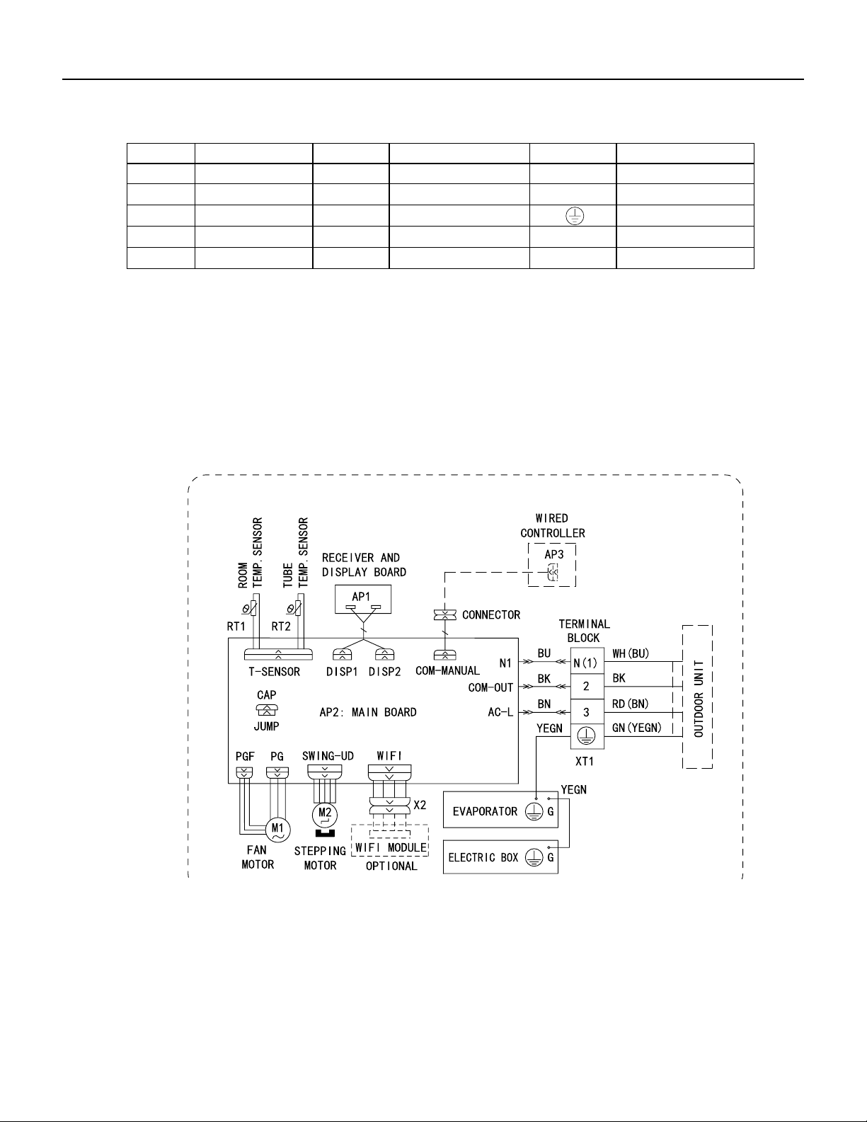
145 PB
WIRING DIAGRAMS
Figure 803
36K Indoor Unit Wiring Diagrams
● Indoor Unit
Symbol Symbol Color Symbol Symbol Color Symbol Name
WH White GN Green CAP Jumper cap
YE Yellow BN Brown COMP Compressor
RD Red BU Blue Grounding wire
YEGN Yellow/Green BK Black / /
VT Violet OG Orange / /
Note: Jumper cap is used to determine fan speed and the swing angle of horizontal lover for this model.
600007000575

146 PB
WIRING DIAGRAMS
Figure 8054 9-12K Outdoor Unit Wiring Diagrams
60000706067401
3
2
N(1)
C3
C4
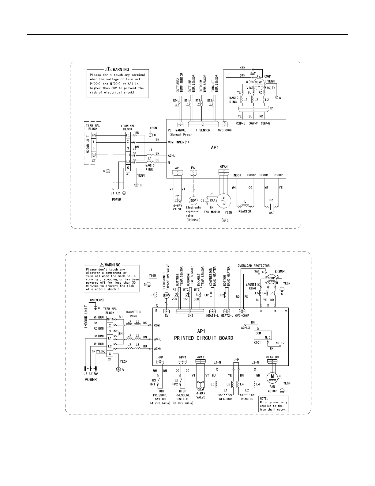
147 PB
WIRING DIAGRAMS
Figure 805
18-24k Outdoor Unit Wiring Diagrams
Figure 806
36k Outdoor Unit Wiring Diagrams
6361000047001
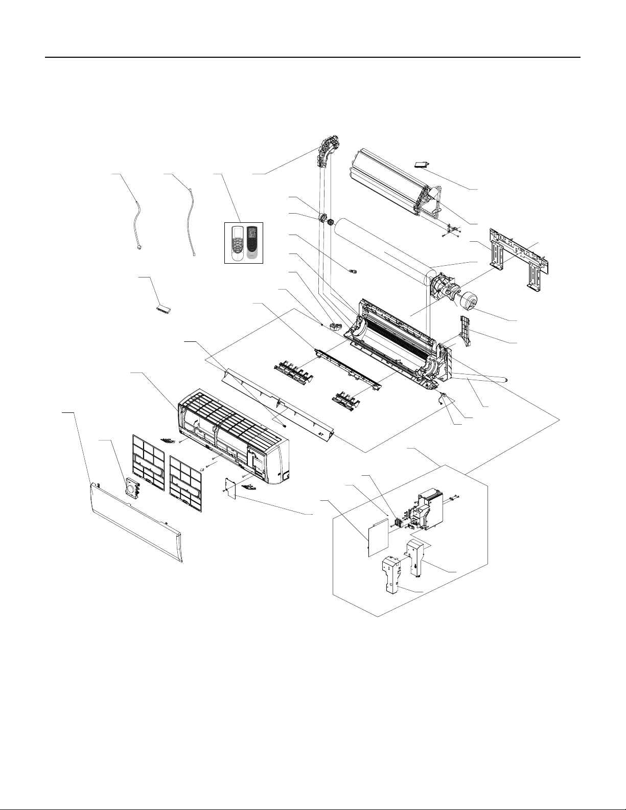
148 PB
FIgure 901
PARTS CATALOG
9K Indoor Unit
292827
30
2
4
9
10
7
12
13
15
16
17
18
19
20
21
22
23
25
26
8
1
3
5
11
14
24
6
6
31
149 PB
FIGURE 901
ITEM PART NUMBER PART DESCRIPTION USED ON MODEL QTY
1 69700627 300036 ‑ Front Panel Assy FSHW09A1A 1
2 69700628 30565260 ‑ Display Board FSHW09A1A 2
3 69700629 2002249501 ‑ Front Case Assy FSHW09A1A 1
4 69700630 26112508 ‑ Helicoid Tongue FSHW09A1A 1
5 69700631 10512037 ‑ Left Axile Bush FSHW09A1A 1
6 69700632 100066 ‑ Rear Case assy FSHW09A1A 1
7 69700633 523001408 ‑ Drainage Hose FSHW09A1A 1
8 69700666 26152022 ‑ Ring of Bearing FSHW09A1A 2
9 69700635 7651205102 ‑ O‑Gasket sub‑assy of
Bearing
FSHW09A1A 2
10 69700636 24212180 ‑ Evaporator Support FSHW09A1A 1
11 #N/A #N/A FSHW09A1A 1
12 69700638 100200004407 ‑ Evaporator Assy FSHW09A1A 1
13 69700639 1252043 ‑ Wall Mounting Frame FSHW09A1A 1
14 69700640 10352059 ‑ Cross Flow Fan FSHW09A1A 1
15 69700641 1501208902 ‑ Fan Motor FSHW09A1A 1
16 69700642 2611216401 ‑ Connecting pipe clamp FSHW09A1A 1
17 69700481 76712012 ‑ Rubber Plug (Water Tray) FSHW09A1A 1
18 69700644 1521212901 ‑ Stepping Motor FSHW09A1A 1
19 69700358 73012005 ‑ Crank FSHW09A1A 1
20 69700646 10000204469 ‑ Electric Box Assy FSHW09A1A 1
21 69700647 10542036 ‑ Axile Bush FSHW09A1A 1
22 69700130 42011233 ‑ Terminal Board FSHW09A1A 1
23 69700649 4202021903 ‑ Jumper FSHW09A1A 1
24 69700650 300002000307 ‑ Main Board FSHW09A1A 1
25 69700651 140206501 ‑ Electric Box Cover Sub‑
Assy
FSHW09A1A 1
26 69700652 1592150 ‑ Shield Cover of Electric Box
Cover
FSHW09A1A 1
27 69700653 2011220701 ‑ Electric Box Cover FSHW09A1A 1
28 #N/A #N/A FSHW09A1A 1
29 #N/A #N/A FSHW09A1A 1
30 #N/A #N/A FSHW09A1A 1
31 69700657 305001000085 ‑ Remote Controller FSHW09A1A 1
32 69700658 409000003 ‑ Checking Panel Assy FSHW09A1A 1
‑ITEMS ARE NON‑ ILLUSTRATED
*ITEMS ARE NON‑STOCKED, WILL NORMALLY REQUIRE 2‑3 WEEKS LEAD TIME
PARTS CATALOG
9k Indoor Unit

150 PB
PARTS CATALOG
12k Indoor Unit
292827
30
2
4
9
10
7
12
13
15
16
17
18
19
20
21
22
23
25
26
8
1
3
5
11
14
24
6
6
31
FIgure 902
151 PB
PARTS CATALOG
12k Indoor Unit
FIGURE 902
ITEM PART NUMBER PART DESCRIPTION USED ON MODEL QTY
1 69700659 300022 ‑ Front Panel Assy FSHSW12A1A 1
2 69700628 30565260 ‑ Display Board FSHSW12A1A 2
3 69700661 200022 ‑ Front Case Assy FSHSW12A1A 1
4 69700662 26112436 ‑ Helicoid Tongue FSHSW12A1A 1
5 69700631 10512037 ‑ Left Axile Bush FSHSW12A1A 1
6 69700664 100093 ‑ Rear Case assy FSHSW12A1A 1
7 69700665 5230014 ‑ Drainage Hose FSHSW12A1A 1
8 69700666 26152022 ‑ Ring of Bearing FSHSW12A1A 2
9 69700635 7651205102 ‑ O‑Gasket sub‑assy of
Bearing
FSHSW12A1A 2
10 69700668 24212179 ‑ Evaporator support FSHSW12A1A 1
11 #N/A #N/A FSHSW12A1A 1
12 69700670 100297601 ‑ Evaporator Assy FSHSW12A1A 1
13 69700333 1252484 ‑ Wall Mounting Frame FSHSW12A1A 1
14 69700672 10352056 ‑ Cross Flow Fan FSHSW12A1A 1
15 69700673 1501214605 ‑ Fan Motor FSHSW12A1A 1
16 69700642 2611216401 ‑ Connecting pipe clamp FSHSW12A1A 1
17 69700481 76712012 ‑ Rubber Plug (Water Tray) FSHSW12A1A 1
18 69700676 1521210710 ‑ SteppingMotor FSHSW12A1A 1
19 69700358 73012005 ‑ Crank FSHSW12A1A 1
20 69700678 10000204444 ‑ Electric Box Assy FSHSW12A1A 1
21 69700647 10542036 ‑ Axile Bush FSHSW12A1A 1
22 69700130 42011233 ‑ Terminal Board FSHSW12A1A 1
23 69700681 4202021906 ‑ Jumper FSHSW12A1A 1
24 69700650 300002000307 ‑ Main Board FSHSW12A1A 1
25 69700651 140206501 ‑ Electric Box Cover Sub‑
Assy
FSHSW12A1A 1
26 69700652 1592150 ‑ Shield Cover of Electric Box
Cover
FSHSW12A1A 1
27 69700653 2011220701 ‑ Electric Box Cover FSHSW12A1A 1
28 #N/A #N/A FSHSW12A1A 1
29 #N/A #N/A FSHSW12A1A 1
30 #N/A #N/A FSHSW12A1A 1
31 69700657 305001000085 ‑ Remote Controller FSHSW12A1A 1
32 69700690 409000004 ‑ Checking Panel Assy FSHSW12A1A 1
‑ITEMS ARE NON‑ ILLUSTRATED
*ITEMS ARE NON‑STOCKED, WILL NORMALLY REQUIRE 2‑3 WEEKS LEAD TIME
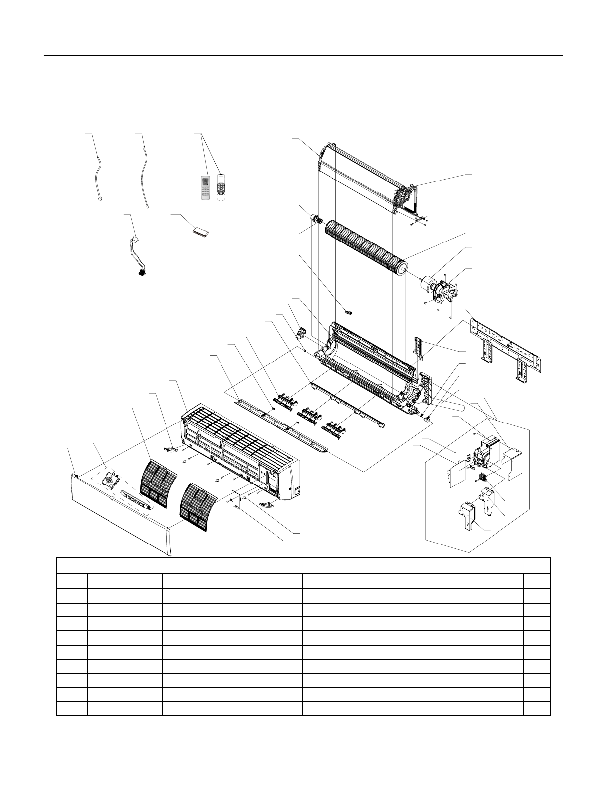
152 PB
PARTS CATALOG
18K Indoor Unit
18K Unit
36
35
1
10
2
3
4
5
6
7
8
9
11
12
13
14
15
16
18
19
20
21
26
25
27
28
29
32
31
24
33
34
37
38 39
22
23
17
30
10
Figure 903
ITEM PART NUMBER PART DESCRIPTION USED ON MODEL QTY
1 69700691 20192703P ‑ Decorative Strip FSHW18A3A 1
2 69700692 300035 ‑ Front Panel Assy FSHW18A3A 1
3 69700628 30565260 ‑ Display Board FSHW18A3A 1
4 69700694 11122089 ‑ Filter Sub‑Assy FSHW18A3A 2
5 69700695 2019261201 ‑ Decorative Board (Left) FSHW18A3A 1
6 69700696 200023 ‑ Front Case Assy FSHW18A3A 1
7 69700697 1051273402 ‑ Guide Louver FSHW18A3A 1
8 69700647 10542036 ‑ Axile Bush FSHW18A3A 2
9 69700699 10512732 ‑ Air Louver(Manual) FSHW18A3A 3
153 PB
PARTS CATALOG
18K Indoor Unit
Figure 903
ITEM PART NUMBER PART DESCRIPTION USED ON MODEL QTY
10 69700700 26112512 ‑ Helicoid Tongue FSHW18A3A 1
11 69700631 10512037 ‑ Left Axile Bush FSHW18A3A 1
12 69700702 22202571 ‑ Rear Case assy FSHW18A3A 1
13 69700481 76712012 ‑ Rubber Plug (Water Tray) FSHW18A3A 1
14 69700635 7651205102 ‑ O‑Gasket sub‑assy of Bearing FSHW18A3A 1
15 69700741 26152025 ‑ Ring of Bearing FSHW18A3A 1
16 69700706 24212177 ‑ Evaporator Support FSHW18A3A 1
17 69700707 11001000207 ‑ Evaporator Assy FSHW18A3A 1
18 69700708 10352060 ‑ Cross Flow Fan FSHW18A3A 1
19 69700709 1501214503 ‑ Fan Motor FSHW18A3A 1
20 69700710 26112511 ‑ Motor Press Plate FSHW18A3A 1
21 69700711 1362026 ‑ Wall Mounting Frame FSHW18A3A 1
22 69700712 2611218801 ‑ Connecting pipe clamp FSHW18A3A 1
23 69700358 73012005 ‑ Crank FSHW18A3A 1
24 69700714 1521240212 ‑ Stepping Motor FSHW18A3A 1
25 69700665 5230014 ‑ Drainage Hose FSHW18A3A 1
26 69700716 10000204259 ‑ Electric Box Assy FSHW18A3A 1
27 69700717 1592139 ‑ Lower Shield of Electric Box FSHW18A3A 1
28 69700718 2011221102 ‑ Electric Box FSHW18A3A 1
29 69700719 4202021909 ‑ Jumper FSHW18A3A 1
30 69700720 300002000312 ‑ Main Board FSHW18A3A
31 69700721 1592176 ‑ Shield Cover of Electric Box FSHW18A3A
32 69700722 2011220901 ‑ Electric Box Cover FSHW18A3A
33 69700130 42011233 ‑ Terminal Board FSHW18A3A
34 69700724 2019261101 ‑ Decorative Board (Right) FSHW18A3A
35 69700725 2425201726 ‑ Screw Cover FSHW18A3A
36 69700726 2011221001 ‑ Electric Box Cover2 FSHW18A3A
37 #N/A #N/A FSHW18A3A
38 #N/A #N/A FSHW18A3A
39 #N/A #N/A FSHW18A3A
40 69700657 305001000085 ‑ Remote Controller FSHW18A3A
41 #N/A #N/A FSHW18A3A
‑ITEMS ARE NON‑ ILLUSTRATED
*ITEMS ARE NON‑STOCKED, WILL NORMALLY REQUIRE 2‑3 WEEKS LEAD TIME
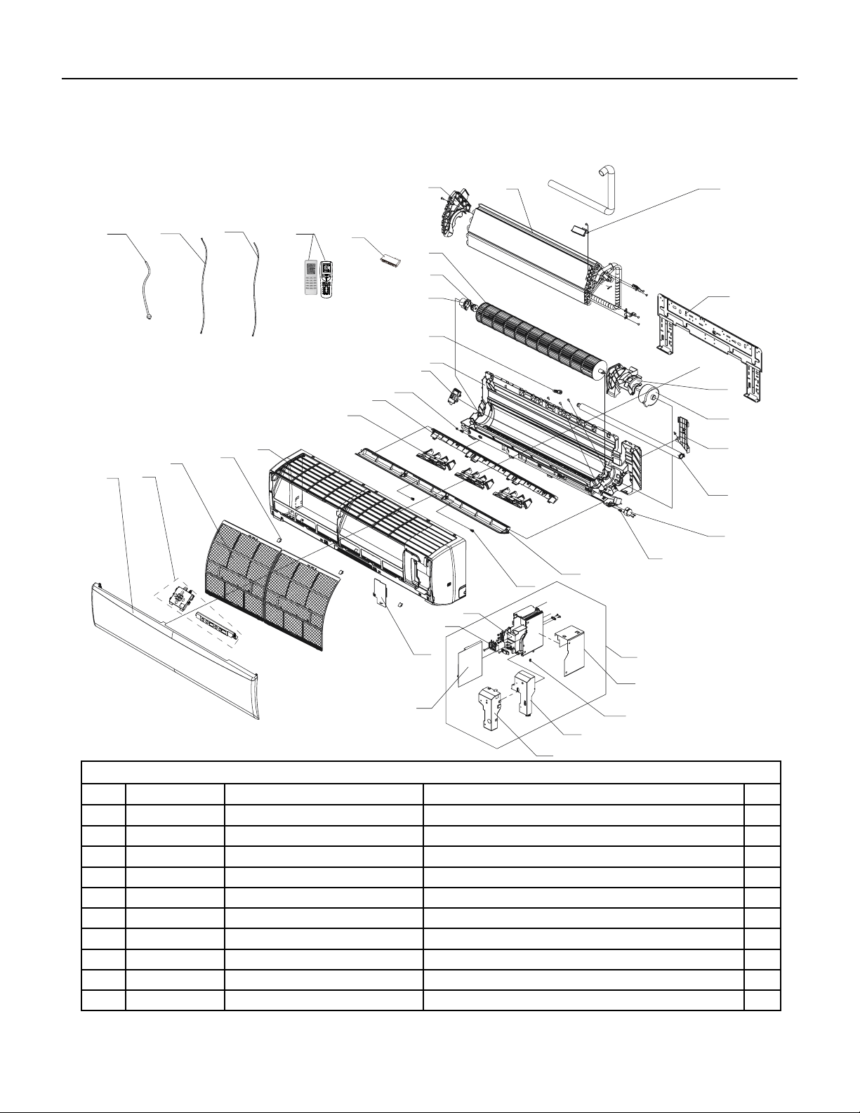
154 PB
PARTS CATALOG
24K Indoor Unit
36
35
37
38
1
8
2
3
4
6
7
9
10
12
13
14
15
17
18
19
20
21
22
23
24
26
27
28
29
30
31
33
5
25
11
16
34
8
32
39
Figure 904
ITEM PART NUMBER PART DESCRIPTION USED ON MODEL QTY
1 69700732 300021 ‑ Front Panel Assy FSHW24A3A 1
2 69700733 11012007 ‑ Filter Sub‑Assy FSHW24A3A 1
3 69700734 2425245301 ‑ Screw Cover FSHW24A3A 1
4 69700735 200116 ‑ Front Case Assy FSHW24A3A 1
5 69700736 10512737 ‑ Air Louver(Manual) FSHW24A3A 1
6 69700737 26112382 ‑ Helicoid Tongue sub‑assy FSHW24A3A 1
7 69700631 10512037 ‑ Left Axile Bush FSHW24A3A 1
8 69700739 22202570 ‑ Rear Case assy FSHW24A3A 1
9 69700481 76712012 ‑ Rubber Plug (Water Tray) FSHW24A3A 1
10 69700741 26152025 ‑ Ring of Bearing FSHW24A3A 1
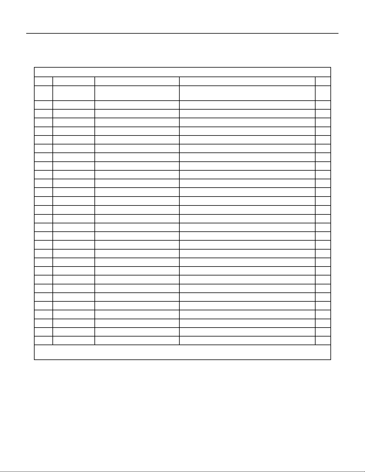
155 PB
PARTS CATALOG
24K Indoor Unit
Figure 904
ITEM PART NUMBER PART DESCRIPTION USED ON MODEL QTY
11 69700635 7651205102 ‑ O‑Gasket sub‑assy of
Bearing
FSHW24A3A 1
12 69700743 10352057 ‑ Cross Flow Fan FSHW24A3A 1
13 69700744 24212178 ‑ Evaporator Support FSHW24A3A 1
14 69700745 11001000095 ‑ Evaporator Assy FSHW24A3A 1
15 #N/A #N/A FSHW24A3A 1
16 69700747 1252229 ‑ Wall Mounting Frame FSHW24A3A 1
17 69700748 26112515 ‑ Motor Press Plate FSHW24A3A 1
18 69700749 1501214501 ‑ Fan Motor FSHW24A3A 1
19 69700750 26112514 ‑ Connecting pipe clamp FSHW24A3A 1
20 69700751 523001405 ‑ Drainage Hose FSHW24A3A 1
21 69700714 1521240212 ‑ Stepping Motor FSHW24A3A 1
22 69700358 73012005 ‑ Crank FSHW24A3A 1
23 69700754 1051273802 ‑ Guide Louver FSHW24A3A 1
24 69700647 10542036 ‑ Axile Bush FSHW24A3A 1
25 69700718 2011221102 ‑ Electric Box FSHW24A3A 1
26 69700130 42011233 ‑ Terminal Board FSHW24A3A 1
27 69700726 2011221001 ‑ Electric Box Cover2 FSHW24A3A 1
28 69700759 300002000316 ‑ Main Board FSHW24A3A 1
29 69700628 30565260 ‑ Display Board FSHW24A3A 1
30 69700721 1592176 ‑ Shield Cover of Electric Box FSHW24A3A 1
31 69700722 2011220901 ‑ Electric Box Cover FSHW24A3A 1
32 69700763 4202021915 ‑ Jumper FSHW24A3A 1
33 69700717 1592139 ‑ Lower Shield of Electric Box FSHW24A3A 1
34 69700765 100002001407 ‑ Electric Box Assy FSHW24A3A 1
35 #N/A #N/A FSHW24A3A 1
36 #N/A #N/A FSHW24A3A 1
37 #N/A #N/A FSHW24A3A 1
38 69700769 3900031302 ‑ Temperature Sensor FSHW24A3A 1
39 69700657 305001000085 ‑ Remote Controller FSHW24A3A 1
‑ITEMS ARE NON‑ ILLUSTRATED
*ITEMS ARE NON‑STOCKED, WILL NORMALLY REQUIRE 2‑3 WEEKS LEAD TIME
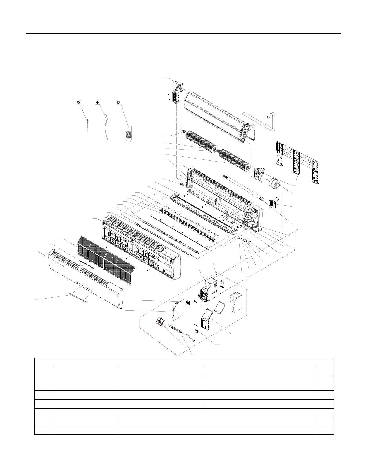
156 PB
PARTS CATALOG
36K Indoor Unit
2
4
5
6
7
15
10
11
17
20
21
22
40
41
42
35
34
32
30
16
39
38
37
31
33
14
36
8
12
13
29
1
3
9
18
19
23
24
25
26
28
27
B2 panel
A3 panel
Figure 905
ITEM PART NUMBER PART DESCRIPTION USED ON MODEL QTY
1 69700592 22430024 ‑ Receiver Window/DIS‑
PLAY COVER
FSHSW36A3A 1
2 69700593 20000300022S ‑ Front Panel FSHSW36A3A 1
3 69700594 2421212001 ‑ Stand Bar FSHSW36A3A 1
4 69700470 11122106 ‑ Filter Sub‑Assy FSHSW36A3A 1
5 69700596 20900700005 ‑ Front Case Sub‑Assy FSHSW36A3A 1
6 69700597 1051216601 ‑ Upper Guide Louver FSHSW36A3A 1

157 PB
PARTS CATALOG
36K Indoor Unit
Figure 905
ITEM PART NUMBER PART DESCRIPTION USED ON MODEL QTY
7 69700598 1051216701 ‑ Lower Guide Louver FSHSW36A3A 1
8 69700599 1051216902 ‑ Air Louver 2 FSHSW36A3A 1
9 69700600 1051216802 ‑ Air Louver 1 FSHSW36A3A 1
10 69700477 10582086 ‑ Connecting Rod/LOUVER
ROD
FSHSW36A3A 1
11 69700478 26112158 ‑ Louver Clamp FSHSW36A3A 1
12 69700603 2018213802 ‑ Water Tray/DRAIN PAN FSHSW36A3A 1
13 69700604 2425200506 ‑ Screw Cover/SCREW
PLUGS
FSHSW36A3A 1
14 69700481 76712012 ‑ Rubber Plug (Water Tray) FSHSW36A3A 1
15 69700606 100113 ‑ Rear Case assy FSHSW36A3A 1
16 69700483 10352039 ‑ Cross Flow Fan 1/
BLOWER 1
FSHSW36A3A 1
17 69700485 10352040 ‑ Cross Flow Fan 2/
BLOWER 2
FSHSW36A3A 1
18 69700487 24212041 ‑ Left Evaporator Support FSHSW36A3A 1
19 69700610 1002000027 ‑ Evaporator Assy/COIL FSHSW36A3A 1
20 69700489 1252398 ‑ Wall Mounting Frame FSHSW36A3A 1
21 69700612 1501213401 ‑ Fan Motor FSHSW36A3A 1
22 69700491 26112071 ‑ Pipe Clamp FSHSW36A3A 1
23 69700614 523001404 ‑ Drainage Hose FSHSW36A3A 1
24 69700615 2012212402 ‑ Cover Plate FSHSW36A3A 1
25 69700494 26112324 ‑ Motor Fixed Clip 1/MOTOR
RETAINER
FSHSW36A3A 1
26 69700617 1521210701 ‑ SteppingMotor FSHSW36A3A 1
27 69700618 100002001022 ‑ Electric Box Assy/
PCB BOARD BOX
FSHSW36A3A 1
28 #N/A #N/A FSHSW36A3A 1
29 69700130 42011233 ‑ Terminal Board FSHSW36A3A 1
30 69700621 300002000255 ‑ Main Board FSHSW36A3A 1
31 69700622 30565277 ‑ Display Board FSHSW36A3A 1
32 69700623 30510475 ‑ Remote Control FSHSW36A3A 1
33 69700624 4001024507 ‑ Signal Wire FSHSW36A3A 1
34 69700510 390000592 ‑ Temperature Sensor/
THERMISTOR
FSHSW36A3A 1
35 69700363 390000453 ‑ Temperature Sensor/
THERMISTOR
FSHSW36A3A 1
‑ITEMS ARE NON‑ ILLUSTRATED
*ITEMS ARE NON‑STOCKED, WILL NORMALLY REQUIRE 2‑3 WEEKS LEAD TIME
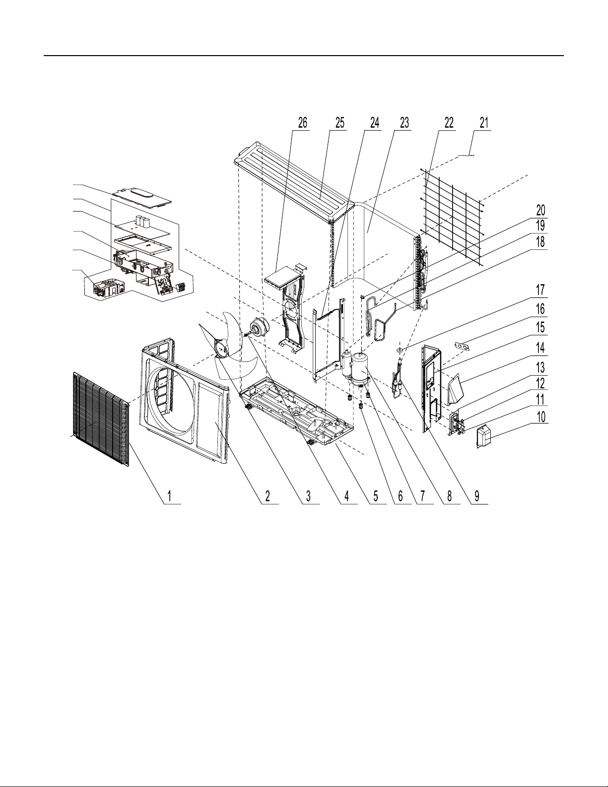
158 PB
FIgure 906
PARTS CATALOG
9K Outdoor Unit
28
27
29
31
30
32
159 PB
Figure 906
ITEM PART NUMBER PART DESCRIPTION USED ON MODEL QTY
1 69700000 1473012 ‑ Front Grill FSHSR09A1A 1
2 69700772 153304901 ‑ Front Panel Assy FSHSR09A1A 1
3 69700773 10333004 ‑ Axial Flow Fan FSHSR09A1A 1
4 69700774 1501308507 ‑ Fan Motor FSHSR09A1A 1
5 69700775 0120388105P ‑ Chassis Sub‑assy FSHSR09A1A 1
6 #N/A #N/A FSHSR09A1A 1
7 69700777 76710302 ‑ Compressor Gasket FSHSR09A1A 1
8 69700268 103862 ‑ Compressor and Fittings FSHSR09A1A 1
9 69700779 30026000199 ‑ Electric Expansion
Valve Sub‑Assy
FSHSR09A1A 1
10 69700780 2012300101 ‑ Valve Cover FSHSR09A1A 1
11 69700009 7100003 ‑ Valve FSHSR09A1A 1
12 69700010 7100005 ‑ Valve FSHSR09A1A 1
13 69700011 1713041 ‑ Valve Support FSHSR09A1A 1
14 69700276 02123014P ‑ Cable Cross Plate 2 FSHSR09A1A 1
15 69700785 02123013P ‑ Cable Cross Plate 1 FSHSR09A1A 1
16 69700786 13030713 ‑ Right Side Plate Assy FSHSR09A1A 1
17 69700787 1413069 ‑ Cover of Pass Wire FSHSR09A1A 1
18 69700788 4300876701 ‑ Electric Expand Valve
Fitting
FSHSR09A1A 1
19 69700283 39000310 ‑ Temperature Sensor FSHSR09A1A 1
20 69700790 3073403 ‑ 4‑Way Valve Assy FSHSR09A1A 1
21 69700213 4300040021 ‑ Magnet Coil FSHSR09A1A 1
22 69700792 180030 ‑ Compressor Overload
Protector(External)
FSHSR09A1A 1
23 69700274 1473057 ‑ Rear Grill FSHSR09A1A 1
24 69700794 11002000509 ‑ Condenser Assy FSHSR09A1A 1
25 69700795 1233034 ‑ Clapboard Sub‑Assy FSHSR09A1A 1
26 69700796 5106001201 ‑ Top Cover Sub‑Assy FSHSR09A1A 1
27 #N/A #N/A FSHSR09A1A 1
28 69700027 260309601 ‑ Electric Box Cover Sub‑
Assy
FSHSR09A1A 1
29 69700799 300027000356 ‑ Main Board FSHSR09A1A 1
30 69700800 100002061853 ‑ Electric Box Assy FSHSR09A1A 1
31 69700803 42010255 ‑ Terminal Board FSHSR09A1A 1
‑32 69700801 100002001953 ‑ Electric Box Assy FSHSR09A1A 1
‑33
n/a n/a n/a
0
‑ITEMS ARE NON‑ ILLUSTRATED
*ITEMS ARE NON‑STOCKED, WILL NORMALLY REQUIRE 2‑3 WEEKS LEAD TIME
PARTS CATALOG
9K Outdoor Unit
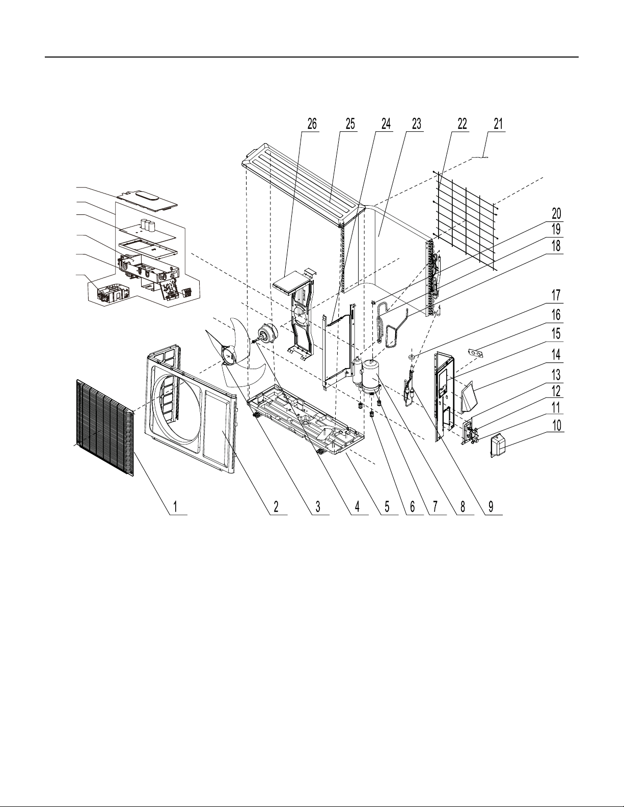
160 PB
PARTS CATALOG
12k Outdoor Unit
28
27
29
31
30
32
FIgure 907
161 PB
Figure 907
ITEM PART NUMBER PART DESCRIPTION USED ON MODEL QTY
1 69700000 1473012 ‑ Front Grill FSHSR12A1A 1
2 69700772 153304901 ‑ Front Panel Assy FSHSR12A1A 1
3 69700773 10333004 ‑ Axial Flow Fan FSHSR12A1A 1
4 69700774 1501308507 ‑ Fan Motor FSHSR12A1A 1
5 69700808 0120388103P ‑ Chassis Sub‑assy FSHSR12A1A 1
6 #N/A #N/A FSHSR12A1A 1
7 69700777 76710302 ‑ Compressor Gasket FSHSR12A1A 1
8 69700268 103862 ‑ Compressor and Fittings FSHSR12A1A 1
9 69700812 30026000185 ‑ Electric Expansion
Valve Sub‑Assy
FSHSR12A1A 1
10 69700780 2012300101 ‑ Valve Cover FSHSR12A1A 1
11 69700814 7130239 ‑ Cut off Valve FSHSR12A1A 1
12 69700010 7100005 ‑ Valve FSHSR12A1A 1
13 69700011 1713041 ‑ Valve Support FSHSR12A1A 1
14 69700276 02123014P ‑ Cable Cross Plate 2 FSHSR12A1A 1
15 69700785 02123013P ‑ Cable Cross Plate 1 FSHSR12A1A 1
16 69700786 13030713 ‑ Right Side Plate Assy FSHSR12A1A 1
17 69700787 1413069 ‑ Cover of Pass Wire FSHSR12A1A 1
18 69700788 4300876701 ‑ Electric Expand Valve
Fitting
FSHSR12A1A 1
19 69700822 3900030903 ‑ Temperature Sensor FSHSR12A1A 1
20 69700790 3073403 ‑ 4‑Way Valve Assy FSHSR12A1A 1
21 69700213 4300040021 ‑ Magnet Coil FSHSR12A1A 1
22 69700792 180030 ‑ Compressor Overload
Protector(External)
FSHSR12A1A 1
23 69700274 1473057 ‑ Rear Grill FSHSR12A1A 1
24 69700827 11002000466 ‑ Condenser Assy FSHSR12A1A 1
25 69700795 1233034 ‑ Clapboard Sub‑Assy FSHSR12A1A 1
26 69700796 5106001201 ‑ Top Cover Sub‑Assy FSHSR12A1A 1
27 #N/A #N/A FSHSR12A1A 1
28 69700027 260309601 ‑ Electric Box Cover Sub‑
Assy
FSHSR12A1A 1
29 69700832 300027000325 ‑ Main Board FSHSR12A1A 1
30 69700833 100002061852 ‑ Electric Box Assy FSHSR12A1A 1
31 69700803 42010255 ‑ Terminal Board FSHSR12A1A 1
‑32 69700834 100002001751 ‑ Electric Box Assy FSHSR12A1A 1
‑33
#N/A #N/A FSHSR12A1A
0
‑ITEMS ARE NON‑ ILLUSTRATED
*ITEMS ARE NON‑STOCKED, WILL NORMALLY REQUIRE 2‑3 WEEKS LEAD TIME
PARTS CATALOG
12k Outdoor Unit
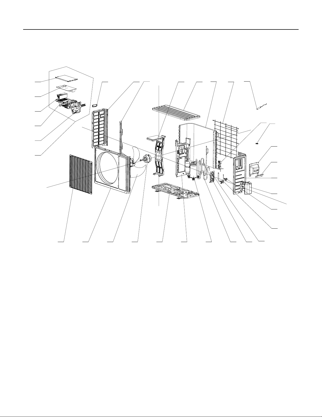
162 PB
PARTS CATALOG
18k Outdoor Unit
FIgure 908
24
8
765
4
321
16
9
15
14
13
12
11
10
23
20
18
30
25
29
28
27
26
21
19
17
22
31
32
163 PB
Figure 908
ITEM PART NUMBER PART DESCRIPTION USED ON MODEL QTY
1 69700837 16004000006 ‑ Front Grill FSHSR18A3A 1
2 69700838 3060055 ‑ Front Panel Assy FSHSR18A3A 1
3 69700839 10335008 ‑ Axial Flow Fan FSHSR18A3A 1
4 69700840 01700000093P ‑ Chassis Sub‑assy FSHSR18A3A 1
5 69700164 6123401 ‑ Drainage Connecter FSHSR18A3A 1
6 69700842 00105249G ‑ Compressor and Fittings FSHSR18A3A 1
7 69700843 30152000291 ‑ 4‑Way Valve Assy FSHSR18A3A 1
8 69700844 01715010P ‑ Valve Support Assy FSHSR18A3A 1
9 69700845 71302392 ‑ Cut off Valve FSHSR18A3A 1
10 69700846 713506803 ‑ Cut off Valve FSHSR18A3A 1
11 69700847 22245002 ‑ Valve Cover FSHSR18A3A 1
12 69700848 26233053 ‑ Handle FSHSR18A3A 1
13 69700849 130329202 ‑ Right Side Plate Assy FSHSR18A3A 1
14 69700850 4300040045 ‑ Magnet Coil FSHSR18A3A 1
15 69700851 26115004 ‑ Wiring Clamp FSHSR18A3A 1
16 69700852 3900030901 ‑ Temperature Sensor FSHSR18A3A 1
17 69700853 1473043 ‑ Rear Grill FSHSR18A3A 1
18 69700854 11002000513 ‑ Condenser Assy FSHSR18A3A 1
19 69700855 1233153 ‑ Clapboard Assy FSHSR18A3A 1
20 69700856 51000017 ‑ Coping Sub‑Assy FSHSR18A3A 1
21 69700857 1703154 ‑ Motor Support Sub‑Assy FSHSR18A3A 1
22 69700858 1501506402 ‑ Fan Motor FSHSR18A3A 1
23 69700859 1173127 ‑ Condenser Support Plate FSHSR18A3A 1
24 69700860 01305093P ‑ Left Side Plate FSHSR18A3A 1
25 69700861 100002001525 ‑ Electric Box Assy FSHSR18A3A 1
26 69700862 20113027 ‑ Electric Box FSHSR18A3A 1
27 69700803 42010255 ‑ Terminal Board FSHSR18A3A 1
28 69700864 49013060 ‑ Radiator FSHSR18A3A 1
29 69700865 300027060416 ‑ Main Board FSHSR18A3A 1
‑ITEMS ARE NON‑ ILLUSTRATED
*ITEMS ARE NON‑STOCKED, WILL NORMALLY REQUIRE 2‑3 WEEKS LEAD TIME
PARTS CATALOG
18kOutdoor Unit
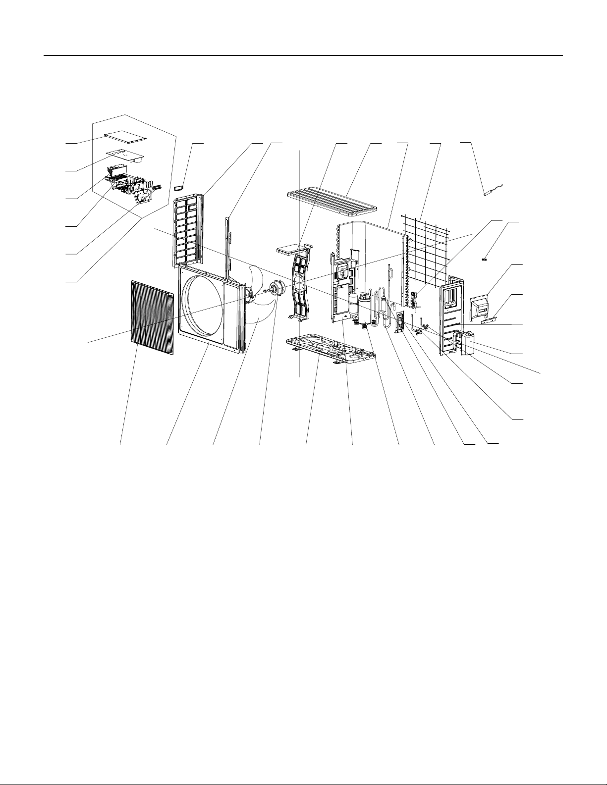
164 PB
PARTS CATALOG
24k Outdoor Unit
FIgure 909
24
8
765
4
321
16
9
15
14
13
12
11
10
23
20
18
30
25
29
28
27
26
21
19
17
22
31
32
165 PB
PARTS CATALOG
24k Outdoor Unit
Figure 909
ITEM PART NUMBER PART DESCRIPTION USED ON MODEL QTY
1 69700837 16004000006 ‑ Front Grill FSHSR24A3A 1
2 69700838 3060055 ‑ Front Panel Assy FSHSR24A3A 1
3 69700839 10335008 ‑ Axial Flow Fan FSHSR24A3A 1
4 #N/A #N/A FSHSR24A3A 1
5 69700870 01700000161P ‑ Chassis Sub‑assy FSHSR24A3A 1
6 #N/A #N/A FSHSR24A3A 1
7 69700842 00105249G ‑ Compressor and Fittings FSHSR24A3A 1
8 69700873 430004032 ‑ 4‑Way Valve FSHSR24A3A 1
9 69700874 30152000073 ‑ 4‑Way Valve Assy FSHSR24A3A 1
10 69700875 3015737 ‑ Capillary Tube FSHSR24A3A 1
11 69700814 7130239 ‑ Cut off Valve FSHSR24A3A 1
12 69700877 130329208 ‑ Right Side Plate Assy FSHSR24A3A 1
13 69700878 01705046P ‑ Valve Support Sub‑Assy FSHSR24A3A 1
14 69700879 7133844 ‑ Cut off Valve FSHSR24A3A 1
15 69700848 26233053 ‑ Handle FSHSR24A3A 1
16 #N/A #N/A FSHSR24A3A 1
17 69700882 3900030902 ‑ Temperature Sensor FSHSR24A3A 1
18 #N/A #N/A FSHSR24A3A 1
19 69700884 1475020 ‑ Rear Grill FSHSR24A3A 1
20 69700885 11002000177 ‑ Condenser Assy FSHSR24A3A 1
21 69700886 1235081 ‑ Clapboard Sub‑Assy FSHSR24A3A 1
22 #N/A #N/A FSHSR24A3A 1
23 69700888 1705067 ‑ Motor Support Sub‑Assy FSHSR24A3A 1
24 69700856 51000017 ‑ Coping Sub‑Assy FSHSR24A3A 1
25 69700860 01305093P ‑ Left Side Plate FSHSR24A3A 1
26 #N/A #N/A FSHSR24A3A 1
27 69700803 42010255 ‑ Terminal Board FSHSR24A3A 1
28 69700893 100002001406 ‑ Electric Box Assy FSHSR24A3A 1
29 69700894 20123028 ‑ Electric Box Cover FSHSR24A3A 1
30 69700895 300027000301 ‑ Main Board FSHSR24A3A 1
‑ITEMS ARE NON‑ ILLUSTRATED
*ITEMS ARE NON‑STOCKED, WILL NORMALLY REQUIRE 2‑3 WEEKS LEAD TIME
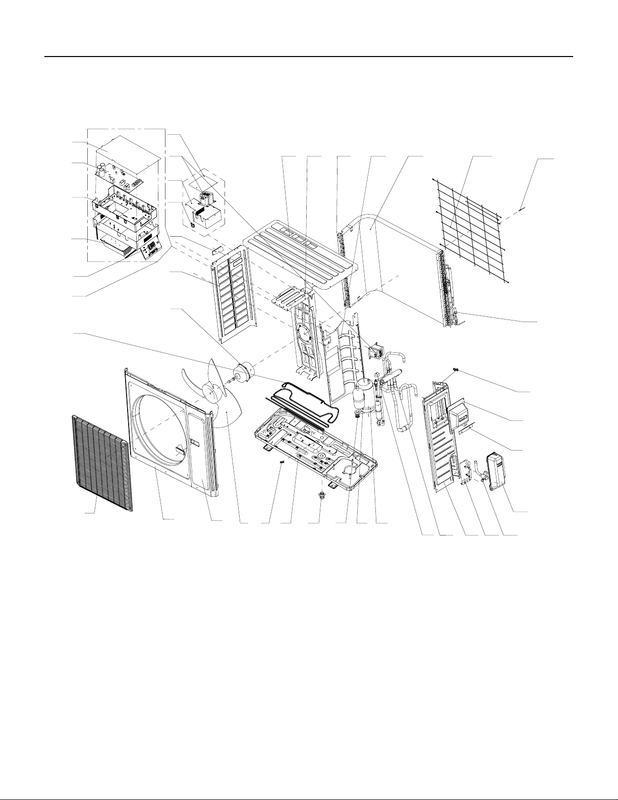
166 PB
PARTS CATALOG
36k Outdoor Unit
FIgure 910
2
6
7
8 9
10
17
18
16
11 12 13 14 15
19
20
21
2223
24
25
26
27
28
29
30
31
32
33
34
35
36
37
38
39
40
41
54
3
1
167 PB
Figure 910
ITEM PART NUMBER PART DESCRIPTION USED ON MODEL QTY
1 69700572 16004060005 ‑ Front Grill FSHSR36A3A 1
2 69700573 153501405 ‑ Front Panel Assy FSHSR36A3A 1
3 69700514 01303249P ‑ Front Side Plate Sub‑
Assy
FSHSR36A3A 1
4 69700515 10335014 ‑ Axial Flow Fan FSHSR36A3A 1
5 #N/A #N/A FSHSR36A3A 1
6 #N/A #N/A FSHSR36A3A 1
7 #N/A #N/A FSHSR36A3A 1
8 69700575 205200003 ‑ Compressor FSHSR36A3A 1
9 69700576 7651873209 ‑ Electrical
Heater(Compressor)
FSHSR36A3A 1
10 69700577 4300040029 ‑ Magnet Coil FSHSR36A3A 1
11 69700578 30152000213 ‑ 4‑Way Valve Assy/
REV VALVE
FSHSR36A3A 1
12 69700522 0130504402P ‑ Right Side Plate FSHSR36A3A 1
13 69700579 0171501201P ‑ Valve Support Sub‑
Assy
FSHSR36A3A 1
14 69700524 7133157 ‑ Cut off Valve FSHSR36A3A 1
15 69700581 2115005 ‑ Shell Handle FSHSR36A3A 1
16 69700582 7200200001201 ‑ Electric expand
valve fitting
FSHSR36A3A 1
17 69700583 3900031001 ‑ Temperature Sensor/
Thermistor
FSHSR36A3A 1
18 69700528 1475013 ‑ Rear Grill FSHSR36A3A 1
19 69700585 1163491 ‑ Condenser Assy FSHSR36A3A 1
20 69700530 1802876 ‑ Motor Support Sub‑Assy FSHSR36A3A 1
21 69700587 51000024 ‑ Top Cover Sub‑Assy FSHSR36A3A 1
22 #N/A #N/A FSHSR36A3A 1
23 69700588 26900000008 ‑ Cable Cross Loop FSHSR36A3A 1
24 #N/A #N/A FSHSR36A3A 1
25 69700533 01305043P ‑ Left Side Plate FSHSR36A3A 1
26 69700590 1570280000405 ‑ Brushless DC Motor FSHSR36A3A 1
27 69700591 100002001028 ‑ Electric Box Assy/
PCB board
FSHSR36A3A 1
‑ITEMS ARE NON‑ ILLUSTRATED
*ITEMS ARE NON‑STOCKED, WILL NORMALLY REQUIRE 2‑3 WEEKS LEAD TIME
PARTS CATALOG
36k Outdoor Unit
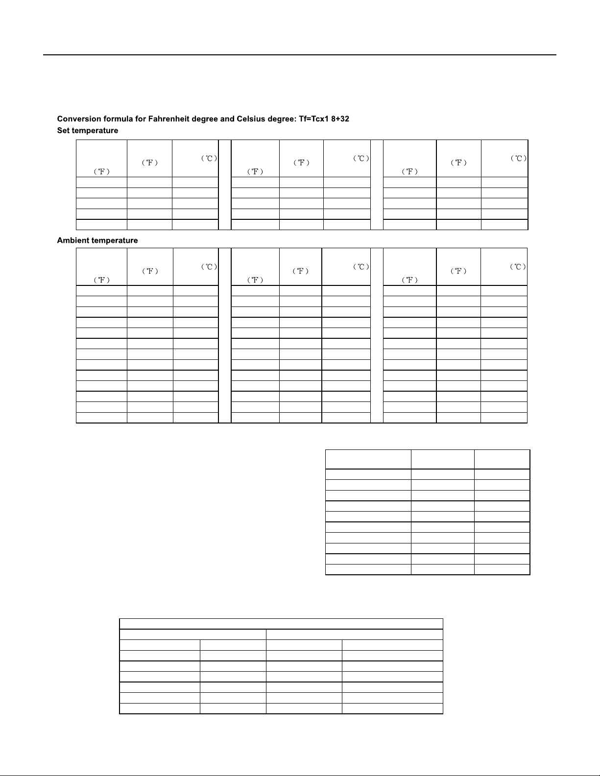
168 PB
APPENDIX
Appendix 1: Reference Sheet of Celsius and Farenheit
.
temperature
display
Fahrenheit
Fahrenheit
Celsius
temperature
display
Fahrenheit
Fahrenheit
Celsius
display
temperature
Fahrenheit
Fahrenheit
32/33
Celsius
32 0 55/56 55.4 13 79/80 78.8 26
34/35 33.8 1 57/58 57.2 14 81 80.6 27
36 35.6 2 59/60 59 15 82/83 82.4 28
37/38 37.4 3 61/62 60.8 16 84/85 84.2 29
39/40 39.2 4 63 62.6 17 86/87 86 30
41/42 41 5 64/65 64.4 18 88/89 87.8 31
43/44 42.8 6 66/67 66.2 19 90 89.6 32
45 44.6 7 68/69 68 20 91/92 91.4 33
46/47 46.4 8 70/71 69.8 21 93/94 93.2 34
48/49 48.2 9 72 71.6 22 95/96 95 35
50/51 50 10 73/74 73.4 23 97/98 96.8 36
52/53 51.8 11 75/76 75.2 24 99 98.6 37
54 53.6 12 77/78 77 25
temperature
Fahrenheit
display
Fahrenheit
Celsius
display
Fahrenheit
temperature
Fahrenheit
Celsius
display
Fahrenheit
temperature
Fahrenheit
61
Celsius
60.8 16 69/70 69.8 21 78/79 78.8 26
62/63 62.6 17 71/72 71.6 22 80/81 80.6 27
64/65 64.4 18 73/74 73.4 23 82/83 82.4 28
66/67 66.2 19 75/76 75.2 24 84/85 84.2 29
68 68 20 77 77 25 86 86 30
Appendix 2: Configuration of Connection Pipe
Diameter of connection pipe
Additional refrigerant charging amount for R22, R407C, R410A and R134a
Outdoor unit throttle
Liquid pipe(inch) Gas pipe(inch) Cooling only(oz/ft.) Cooling and heating(oz/ft.)
Ф1/4 Ф3/8or Ф1/2 0.2 0.2
Ф1/4 or Ф3/8 Ф5/8 or Ф3/4 0.2 0.2
Ф1/2 Ф3/4 or Ф7/8 0.3 1.3
Ф5/8 Ф1 or Ф1 1/4 0.7 1.3
Ф3/4 / 2.7 2.7
Ф7/8 / 3.8 3.8
Cooling capacity
Max height Max length of
connection pipe
5000 Btu/h(1465 W)
dierence
49.21ft 16.40ft
7000 Btu/h(2051 W) 49.21ft 16.40ft
9000 Btu/h(2637 W) 49.21ft 32.81ft
12000 Btu/h(3516 W) 65.62ft 32.81ft
18000 Btu/h(5274 W) 80.02ft 32.81ft
24000 Btu/h(7032 W) 80.02ft 32.81ft
28000 Btu/h(8204 W) 98.43ft 32.81ft
36000 Btu/h(10548 W) 98.43ft 65.62ft
42000 Btu/h(12306 W) 98.43ft 65.62ft
48000 Btu/h(14064 W) 98.43ft 65.62ft
1.Standard length of connection pipe
16.40ft, 24.61ft, 26.25ft.
2.Min. length of connection pipe is 9.84ft.
3.Max. length of connection pipe and max. high dierence.
4.The additional refrigerant oil and refrigerant charging required after
prolonging connection pipe
basis of standard length, you should add 5ml of refrigerant oil for each
additional 16.40ft of connection pipe.
the basis of liquid pipe):
The calculation method of additional refrigerant charging amo unt (on
After the length of connection pipe is prolonged for 32.81ft at the
When the length of connection pipe is above 16.40ft, add refrigerant according to the prolonged length of liquid pipe. The
additional refrigerant charging amount per meter is dierent according to the diameter of liquid pipe. See the following sheet.
Additional refrigerant charging amount = prolonged length of liquid pipe X additional refrigerant charging amount per meter
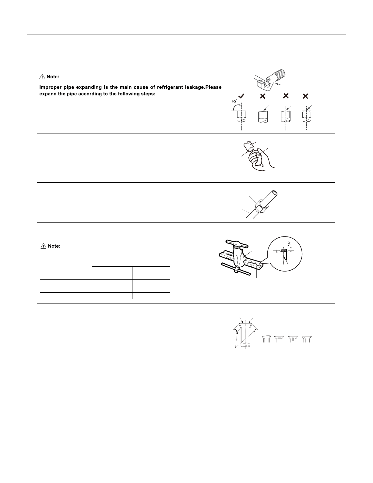
169 PB
APPENDIX
Appendix 3: Pipe Expanding Method
F:Inspection
Improper expanding
The length is equal
surface
leaning
damaged
Check the quality of expanding port. If there is any blemish, expand the
port again according to the steps above.
crack uneven
thickness
Smooth surface
Downwards
Pipe
Shaper
Union pipe
Pipe
Expander
Hard
mold
Pipe
Pipe
Pipe cutter
Leaning Uneven Burr
B:Remove the burrs
C:Put on suitable insulating pipe
Confirm the pipe length according to the distance of indoor unit and outdoor unit.
Cut the required pipe with pipe cutter.
D:Put on the union nut
Remove the burrs with shaper and prevent the burrs from getting into the pipe.
A:Cut the pip
E:Expand the port
Remove the union nut on the indoor connection pipe and outdoor valve; install
the union nut on the pipe.
Outer diameter(inch)
A(inch)
Max Min
Ф1/4
Expand the port with expander.
"A" is dierent according to the diameter, please refer to the sheet below:
2/39 1/36
Ф3/8 1/16 1/51
Ф1/2 1/14 1/51
Ф5/8 5/53 2/23

170 PB
Friedrich Air Conditioning Company
10001 Reunion Place, Suite 500
San Antonio, TX 78216
800-541-6645
www.friedrich.com
FLOATING AIR DUCTLESS SPLIT SYSTEMS
LIMITED WARRANTY
1. A) FIVE YEAR WARRANTY - FRIEDRICH AIR CONDITIONING CO. (FRIEDRICH) warrants to the original end‑user of this product that should it
prove defective due to improper workmanship and/or material under normal use for a period of five years from the date of installation, FRIEDRICH
will repair or replace, at its option, any defective part without charge for the part. Replacement parts are warranted for the remainder of the original
warranty period.
B) THIS WARRANTY DOES NOT INCLUDE LABOR or other cost incurred for servicing, repairing, removing, installing,
shipping, or handling of either defective or replacement parts, or complete unit. Such cost may be covered by a separate warranty provided by the
installing contractor.
C) FIVE YEAR COMPRESSOR WARRANTY- During the five year warranty period from the date of installation, should the compressor prove defective
due to improper workmanship and/or material, FRIEDRICH will furnish a replacement compressor, at no charge, which is warranted for the remain‑
der of the original warranty period. LABOR IS NOT INCLUDED FOR INSTALLING REPLACEMENT COMPRESSOR.
These warranties apply only while the unit remains at the original site and only to units installed inside the continental United States, Alaska,
Hawaii, Puerto Rico, Mexico and Canada. The warranty applies only if the unit is installed and operated in accordance with the printed instructions
and in compliance with applicable local installation and building codes and good trade practices. For international warranty information, contact the
Friedrich Air Conditioning Company - International Division.
D) NOTICE: To obtain service and/or warranty parts replacement, you must notify an authorized FRIEDRICH Air Conditioning Co. distributor, dealer,
or contractor of any defect within the applicable warranty period.
2. Any defective part to be replaced must be made available to FRIEDRICH in exchange for the replacement part. You must present proof of the
original date of installation of the product in order to establish the effective date of the warranty. Otherwise, the effective date will be deemed to be
the date of manufacture plus thirty days. The return of the owner registration card is not a condition of warranty coverage. However, please detach
and return it so that we can contact you should a question of safety arise which could affect you.
3. TO OBTAIN WARRANTY SERVICE, please contact your authorized FRIEDRICH distributor, dealer, or the contractor who installed the equipment. If
your dealer or contractor needs assistance, the authorized FRIEDRICH distributor is available for consultation, and FRIEDRICH supports the efforts
of the distributor.
4. This limited warranty applies only to units remaining at the site of the original installation (except for mobile home installations) and only to units
installed within the continental United States, Alaska, Hawaii, and Canada. This limited warranty applies only if the unit is installed and operated in
accordance with FRIEDRICH instructions and in compliance with applicable local installation and building codes and good trade practices.
5. THIS WARRANTY DOES NOT COVER damages caused by: (a) accident, abuse, negligence, or misuse; (b) operating the product in a corrosive
atmosphere containing chlorine, fluorine or any other damaging chemicals; (c) modification, alteration, poor service practices; (d) improper match‑
ing or application of the product or components; (e) failure to provide proper maintenance and service to the product according to manufacture’s
instructions; (f) installation or operating of the product in a manner contrary to the instructions of the manufacturer; (g) lightning, fluctuations in
electrical power or other Acts of God. This LIMITED WARRANTY also excludes all cost of installation, disconnection or dismantling the product, parts
used in connection with normal maintenance such as air filters or belts and owner‑required maintenance. Consult the instructions enclosed with the
product for information regarding recommended maintenance.
6. No one is authorized to change this LIMITED WARRANTY in any respect, or to create any other obligation or liability in connection with this prod‑
uct.
7. YOUR ONLY REMEDIES ARE PROVIDED IN THIS LIMITED WARRANTY. ANY EXPRESS WARRANTY NOT PROVIDED HEREIN, AND ANY REMEDY
WHICH, BUT FOR THIS PROVISION, MIGHT ARISE BY IMPLICATION OR OPERATION OF LAW, IS HEREBY EXCLUDED AND DISCLAIMED. THE
IMPLIED WARRANTIES OF MERCHANTABILITY AND OF FITNESS FOR ANY PARTICULAR PURPOSE ARE EXPRESSLY LIMITED TO A TERM OF ONE
YEAR FROM THE DATE OF ORIGINAL INSTALLATION. UNDER NO CIRCUMSTANCES SHALL FRIEDRICH BE LIABLE TO THE OWNER OR ANY OTHER
PERSON FOR ANY INCIDENTAL, SPECIAL OR CONSEQUENTIAL DAMAGES IN CONNECTION WITH THIS PRODUCT, WHETHER ARISING OUT OF
BREACH OF WARRANTY, BREACH OF CONTRACT OR OTHERWISE.
8. Some states do not allow limitations on how long an implied warranty lasts and/or do not allow the exclusion or limitation of incidental, special or
consequential damages, so the above limitations or exclusions may not apply to you.
9. This warranty gives you specific legal rights, and you may have other rights which vary from state to state and province to province.

171 PB
Friedrich Air Conditioning Co.
10001 Reunion Place, Suite 500 • San Antonio, Texas 78216
1‑800‑541‑6645
www.friedrich.com
TECHNICAL SUPPORT
CONTACT INFORMATION
CUSTOMER SATISFACTION and QUALITY ASSURANCE
Friedrich is a conscientious manufacturer, concerned about customer satisfaction, product quality, and controlling
warranty costs. As an Authorized Service Provider you play a vital role in these areas. By adhering to the policies
and procedures you provide us with vital information on each warranty repair you complete. This information
is used to identify product failure trends, initiate corrective action, and improve product quality, thereby further
reducing warranty expenses while increasing customer satisfaction levels.
FRIEDRICH AUTHORIZED PARTS DEPOTS
AAA Refrigeration Service
1322 24th Street, Suite B Kenner,
Louisiana 70062 504-464-7444
877-813-7444
Alamo Service Company
1450 North Flores Street San
Antonio, Texas 78212 210-227-
2450
800-328-2450
The Gabbert Company
6868 Ardmore
Houston, Texas 77054
713-747-4110
800-458-4110
Johnstone Supply of Woodside
27-01 Brooklyn Queens Expway
Woodside, New York 11377 718-
545-5464
800-431-1143
Reeve Air Conditioning, Inc.
2501 South Park Road Hallandale, Florida
33009 954-962-0252
800-962-3383