
Loading ...
Loading ...
Loading ...
PREPARATIONS ➤ Connecting playback devices En 25
The unit is equipped with a variety of input jacks including HDMI input jacks to allow
you to connect different types of playback devices. For information on how to connect
an iPod or a USB storage device, see the following pages.
– Connecting an iPod (p.63)
– Connecting a USB storage device (p.66)
Connecting video devices (such as BD/DVD players)
Connect video devices such as BD/DVD players, set-top boxes (STBs) and game
consoles to the unit. Depending on the video/audio output jacks available on your video
device, choose one of the following connections. We recommend using an HDMI
connection if the video device has an HDMI output jack.
• If the combination of video/audio input jacks available on the unit does not match your video device, change
its combination according to the output jacks of your device (p.26).
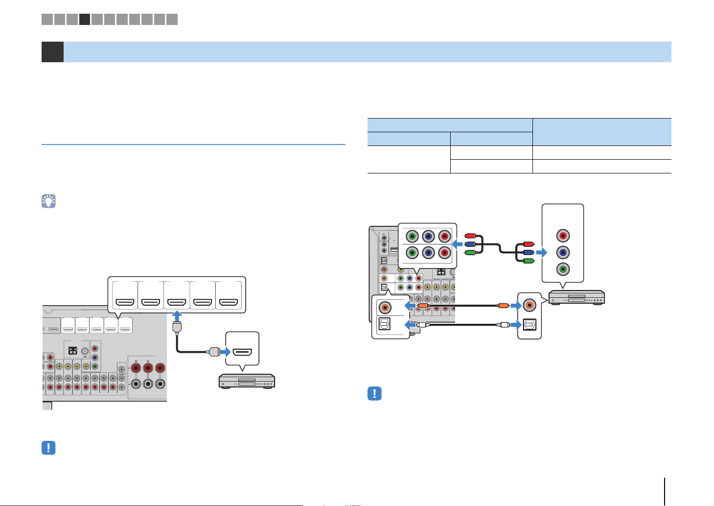
■ HDMI connection
Connect a video device to the unit with an HDMI cable.
If you select the input source by pressing HDMI 1–5, the video/audio played back on
the video device will be output from the unit.
• To watch videos input to the HDMI 1–5 jacks, you need to connect your TV to the HDMI OUT jack of the
unit (p.23).
■ Component video connection
Connect a video device to the unit with a component video cable and an audio cable
(digital optical or digital coaxial). Choose a set of input jacks (on the unit) depending on
the audio output jacks available on your video device.
If you select the input source by pressing AV 1–2, the video/audio played back on the
video device will be output from the unit.
• The component video signals (other than 480i/576i signals) input to AV 1–2 jacks of the unit can be output
from the MONITOR OUT (COMPONENT VIDEO) jacks only. To watch those videos, you need to connect
your TV to the MONITOR OUT (COMPONENT VIDEO) jacks of the unit (p.23). For details, refer to “Video
signal flow” (p.133).
4 Connecting playback devices
O
1
AUDIO 2
P
R
COMPONENT
VIDEO
VIDEO
MONITOR OUT
P
B
Y
P
R
HDMI 1 HDMI 2 HDMI 3 HDMI 4 HDMI 5
(
BD/DVD
)
1
ARC
ANTENNA
FM
AM
FRONT CENTER
SPEAKERS
AV 5
VIDEO
AV 6
AV OUT
ZONE OUT
SUBWOOFER
SUR. BACKSURROUND
FRONT
PRE OUT
CENTER
SINGLE
ZONE 2
T
VIDEO
CENTER
1
2
H
DMI
OUT
(
RADIO
)
HDMI
HDMI
HDMI
HDMI 1 HDMI 2 HDMI 3 HDMI 4 HDMI 5
(
BD/DVD
)
The unit (rear)
HDMI output
Video device
HDMI 1–5 jacks
Output jacks on video device
Input jacks on the unit
Video Audio
Component video
Digital optical AV 1 (COMPONENT VIDEO + OPTICAL)
Digital coaxial AV 2 (COMPONENT VIDEO + COAXIAL)
AUDIO 1
AUDIO 2
OPTICAL
OPTICAL
COAXIAL
VIDEO
AV4
AV3
AV2
AV 1
(TV)
P
B
Y
P
R
VID
E
M
O
HDMI 1 HDMI 2
(
BD/DVD
)
12
ARC
ANTENNA
FM
AM
AV 5
VIDEO
AV 6
AV OUT
ZONE
ZON
E
DC OUT
TRIGGER OUT
REMOTE
5V
0.5A
12V
IN
OUT
0.1A
COMPONENT VIDEO
HDMI
OUT
(
RADIO
)
COAXIAL
OPTICAL
PR
PB
Y
COMPONENT
VIDEO
OPTICAL
AV2
AV 1
P
B
Y
P
R
COMPONENT VIDEO
O
O
C
C
P
R
P
B
Y
P
R
P
B
Y
The unit
(rear)
AV 1–2
(COMPONENT VIDEO)
jacks
Video output
(component video)
Video device
Audio output
(digital optical or digital coaxial)
AV 1 (OPTICAL) jack or
AV 2 (COAXIAL) jack
1 2 3 4 5 6 7 8 9 10 11
Loading ...
Loading ...
Loading ...