SERVICE MANUAL
BUILT IN WINE CELLAR
MODEL : SKSCW181RP
SKSCW241RP
CONFIDENTIAL
www.signaturekitchensuite.com
MFL67262420
Any reproduction, duplication, distribution (including by way of email, facsimile or other electronic means), publication,
modication, copying or transmission of this Service Manual is STRICTLY PROHIBITED unless you have obtained
the prior written consent of the SIGNATURE KITCHEN SUITE entity from which you received this Service Manual.
The material covered by this prohibition includes, without limitation, any text, graphics or logos in this Service Manual.
Copyright © 2018 - 2019 SIGNATURE KITCHEN SUITE. All rights reserved. Only training and service purposes.

- 2 -
Copyright © 2018-2019 SIGNATURE KITCHEN SUITE.
All rights reserved. Only training and service purposes.
CONTENTS
1. SAFETY PRECAUTIONS ............................................................................................................................................................ 3
2. PRODUCT STANDARDS ............................................................................................................................................................ 4
3. CIRCUIT DIAGRAM .................................................................................................................................................................5-6
4. SPECIFICATIONS ....................................................................................................................................................................7-9
5. MICOM FUNCTION ..............................................................................................................................................................10-11
6. TROUBLE SHOOTING.........................................................................................................................................................12-24
7. TROUBLE SHOOTING WITH ERROR DISPLAY ................................................................................................................ 25-43
8. HOW TO DISASSEMBLE AND ASSEMBLE
1. Door ........................................................................................................................................................................................44
2. Knock-on ..........................................................................................................................................................................45-46
3. Top Cover ..............................................................................................................................................................................47
4. Door Switch / SDS PCB / Temperature sensor ..................................................................................................................48
5. Machine Room Cover ........................................................................................................................................................... 49
6. Machine Room Cycle.......................................................................................................................................................50-53
7. Wi-Fi .......................................................................................................................................................................................54
8. Power Cord ............................................................................................................................................................................55
9. Main PCB ..........................................................................................................................................................................56-57
10. Control Panel ......................................................................................................................................................................58
11. Shelf .....................................................................................................................................................................................59
12. Slide Rail ............................................................................................................................................................................. 60
13. Holder Rail .......................................................................................................................................................................... 61
14. Top Duct ...............................................................................................................................................................................62
15. Grille Fan .............................................................................................................................................................................63
16. Multi Duct ............................................................................................................................................................................64
17. Defrost Sensor ...................................................................................................................................................................65
18. Barrier ..................................................................................................................................................................................66
9. SEALED SYSTEM REPAIR METHOD OF REFRIGERATOR WITH R600A REFRIGERANT ...........................................67-73
10. EXPLODED VIEW .............................................................................................................................................................74-81

- 3 -
Copyright © 2018-2019 SIGNATURE KITCHEN SUITE.
All rights reserved. Only training and service purposes.
1. SAFETY PRECAUTIONS
Please read the following instructions before servicing your refrigerator.
1. Unplug the powr before handing any electrical componets.
2. Check the rated current, voltage, and capacity.
3. Take caution not to get water near any electrical components.
4. Use exact replacement parts.
5. Remove any objects from the top prior to tilting the product.
- 4 -
Copyright © 2018-2019 SIGNATURE KITCHEN SUITE.
All rights reserved. Only training and service purposes.
2. PRODUCT STANDARDS
Model Name
SKSCW181RP SKSCW241RP
Effective inner capacity 274L (9.7 Cu.ft) 385L (13.6 Cu.ft)
Outer dimension (W x D x H)
"445 × 607× 2121 mm
(17 1/2 x 23 7/8 x 83 1/2 inch)"
"603 × 607× 2121 mm
(23 3/4 x 23 7/8 x 83 1/2 inch)"
Rated voltage and frequency 115V / 60Hz 115V / 60Hz
Product weight (kg) 139kg (306lb) 162kg (357lb)
Cooling method Fan Cooling Fan Cooling
Defrost system Natural Defrost system Natural Defrost system
Lay-out
Room 2 (1 Barrier) 3 (2 Barrier)
Shelf 9 (Upper:4EA, Lower:5EA) 8 (Upper:4EA, Mid:2EA, Lower:2EA)
Temperature
control
Upper-Room Micom Control Micom Control
Middle-Room - Micom Control
Lower-Room Micom Control Micom Control
Cycle
Compressor driving method
Linear Linear
Evaporator Rollbond Type Rollbond Type
Condenser Micro Channel Condenser (Al) Micro Channel Condenser (Al)
Compressor Oil Mineral / Freol Alpha 3G (3cst) (120cc) Mineral / Freol Alpha 3G (3cst) (120cc)
Type of refrigerant R 600a (42g) R 600a (44g)
Capillary tube 0.75 0.75
Dryer (Capillary Tube) Molecular-sieves XH-9 Molecular-sieves XH-9
Valve 3Way Valve 4Way Valve
"Electrical parts
standard"
Heater AC 115V / 33W * 2EA AC 115V / 33W * 3EA
Overload protective device 4MPS41F9-01 4MPS41F9-01
Cold Fan motor DC 12V DC 12V
Fan motor for cooling
condenser
DC 12V DC 12V
Inside lamp
15.4W 28.2W
Main Fuse 125V / 10A 125V / 10A
Valve DC 12V DC 12V
Model Name
- 5 -
Copyright © 2018-2019 SIGNATURE KITCHEN SUITE.
All rights reserved. Only training and service purposes.
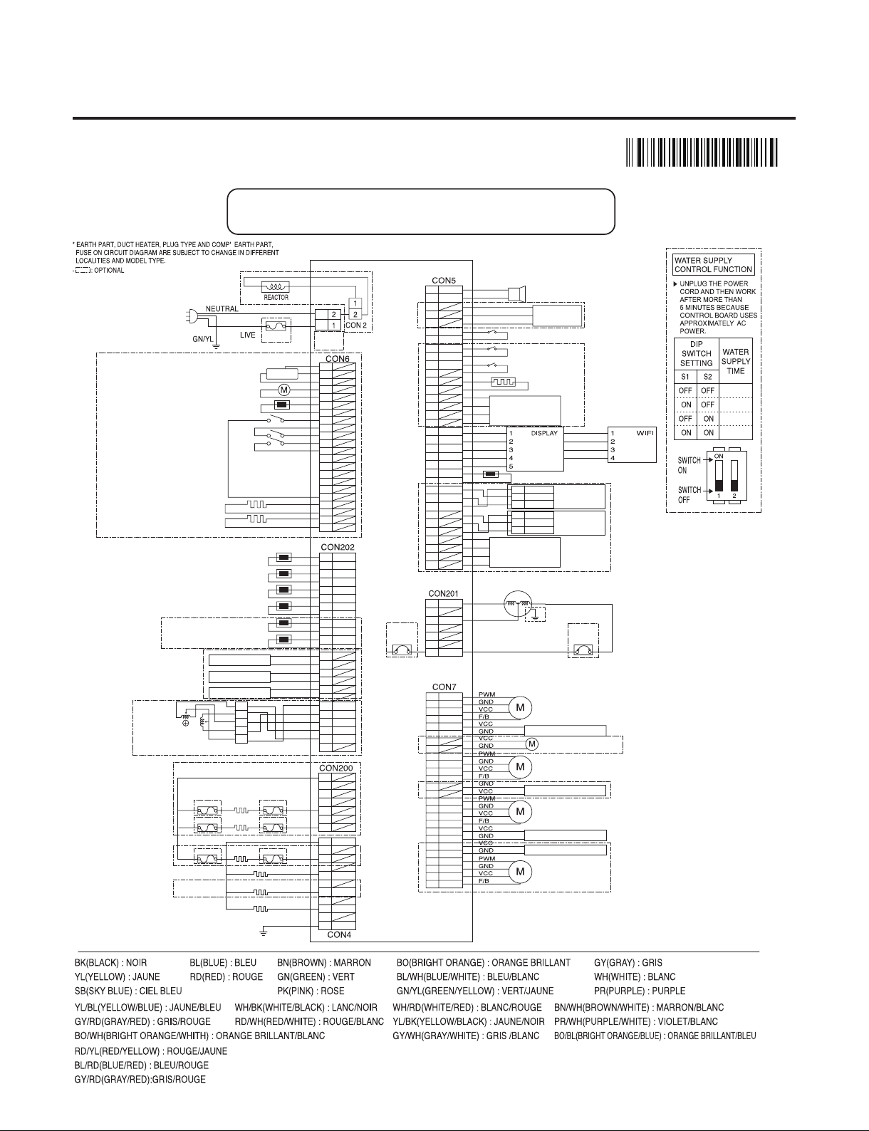
3. CIRCUIT DIAGRAM
MBM6633
5905
24” : W1(Upper)/W2(Middle)/W3(Lower)
18” : W1(Upper)/W2(Lower)
CON1/
CON1_1
2
4
6
8
10
12
14
16
18
20
1
3
5
7
9
11
13
15
17
22
21
19
WATER PIPE HEATER
DEW HEATER
HALL IC
ICE MAKER SENSOR
ICE MAKER MOTOR
POWER
CORD
FUSE
ICE MAKER MOTOR TEST SWITCH
DISPENSER SWITCH
ICE MAKER MOTOR ON-OFF SWITCH
WH
WH
BK
BK
RD
RD
BO
BO
BL
BL
SB
GY/RD
WH/BK
YL
PK
BO/BL
BO/BL
1
3
5
7
9
11
13
15
17
19
21
23
2
4
6
8
10
12
14
16
18
20
22
24
VCC
GND
VCC
GND
VCC
GND
COM
A
B
B-
A-
1
2
5
6
3.4
3WAY/4WAY
VALVE
1
3
5
7
2
4
6
8
9
11
13
15
17
19
21
23
25
26
10
12
14
16
18
20
22
24
W1 FAN
MACHINE ROOM FAN
HYGIENE LED LIGHT
HYGIENE FAN MOTOR
W1 LED PWM LIGHT
W2 FAN
W3 FAN
YL
GY
BO
RD
BL
PK
RD/YL
YL/BL
WH/BN
PR/WH
BK
BN
PR
WH
WH/RD
BL/RD
SB/BK
BO/WH
BO/BL
YL/BK
WH/BK
BL/WH
W2 LED PWM LIGHT
W3 LED PWM LIGHT
SMART
BUZZER
H_SENSOR
DOOR 1 SWITCH
DOOR 2 SWITCH
DOOR 3 SWITCH
DAMPER
HEATER
H_SENSOR
BK
SB
PK
BL/WH
BL/WH
1
1
2
3
3
5
7
9
11
13
15
17
19
21
A
5V
GND
A-
B-
5V
GND
SIG
B
23
25
27
29
31
33
4
2
6
8
10
12
14
16
18
20
22
24
26
28
30
32
34
OUTDOOR SENSOR
RD
GY/WH
BL
BO
WH/RD
BN
BN
STEPPING
MOTOR DAMPER
STEPPING
MOTOR DAMPER
A
A-
B-
B
KNOCK ON
SENSOR 1
YL
BK
RD
1
2
3
5V
GND
SIG
KNOCK ON
SENSOR 2
YL
BK
RD
PR
BO/WH
12V
5V
5V
TX
RX
GND
GND
RX
TX
LINEAR
COMPRESSOR
COMPRESSOR
GROUNDING
OVERLOAD
PROTECTION
DEVICE
OVERLOAD
PROTECTION
DEVICE
BL
RD
BK
1
2
3
4
5
6
7
CIRCUIT DIAGRAM
8.0 SEC
9.0 SEC
10.0 SEC
11.0 SEC
D-N※ D-N : Defrosting Heater- N
GROUNDING
1
2
3
4
5
6
7
FUSE-M
FUSE-M
FUSE-M
FUSE-M
FUSE-M
FUSE-M
W2
DEFROSTING
HEATER
W2 DEFROSTING HEATER
W3 DEFROSTING HEATER
W1 DEFROSTING HEATER
W1
DEFROSTING
HEATER
W3
DEFROSTING
HEATER
1
2
3
4
5
6
7
8
9
10
11
PK
BN
WH
BK
GR/YL
WH
BK
W1 SENSOR
W1 DEFROSTING SENSOR
W2 SENSOR
W2 DEFROSTING SENSOR
W3 SENSOR
W3 DEFROSTING SENSOR
W1 LED LIGHT
W2 LED LIGHT
W3 LED LIGHT
- 6 -
Copyright © 2018-2019 SIGNATURE KITCHEN SUITE.
All rights reserved. Only training and service purposes.
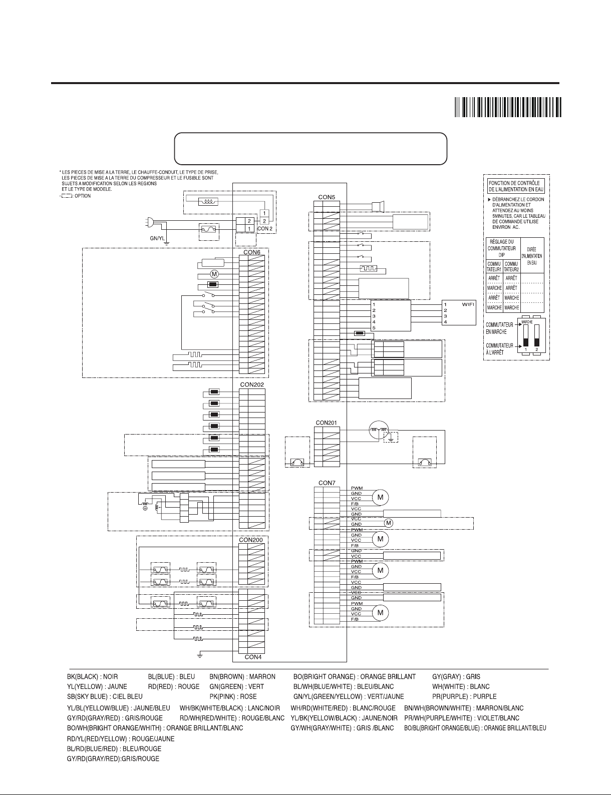
3. CIRCUIT DIAGRAM
MBM66335905
24” : W1(supérieur)/W2(Moyen)/W3(*OG¨SJFVS)
18” : W1(supérieur)/W2(*OG¨SJFVS)
CON1/
CON1_1
2
4
6
8
10
12
14
16
18
20
1
3
5
7
9
11
13
15
17
22
21
19
CHAUFFAGE DE LA CONDUITE D’EAU
CHAUFFAGE DE LA ROSÉE
CIRCUIT INTÉGRÉ EFFET HALL
CAPTEUR DE L’APPAREIL À GLAÇONS
MOTEUR DE L’APPAREIL À GLAÇONS
FICHE
SECTEUR
FUSIBLE
INTERRUPTEUR DE TEST MOTEUR DE L’APPAREIL À GLAÇONS
INTERRUPTEUR DU DISTRIBUTEUR
INTERRUPTEUR MARCHE/ARRÊT MOTEUR DE L’APPAREIL À GLAÇONS
WH
WH
BK
BK
RD
RD
BO
BO
BL
BL
SB
GY/RD
WH/BK
YL
PK
BO/BL
BO/BL
1
3
5
7
9
11
13
15
17
19
21
23
2
4
6
8
10
12
14
16
18
20
22
24
CAPTEUR W1
CAPTEUR DE DÉGIVRAGE W1
CAPTEUR W2
CAPTEUR DE DÉGIVRAGE W2
CAPTEUR W3
CAPTEUR DE DÉGIVRAGE W3
ÉCLAIRAGE LED W1
ÉCLAIRAGE LED W2
ÉCLAIRAGE LED W3
VCC
GND
VCC
GND
VCC
GND
COM
A
B
B-
A-
1
2
5
6
3.4
SOUPAPE
3 VOIES/4 VOIES
1
3
5
7
2
4
6
8
9
11
13
15
17
19
21
23
25
26
10
12
14
16
18
20
22
24
VENTILATEUR W1
VENTILATEUR LOCAL TECHNIQUE
LAMPE LED HYGIÈNE
MOTEUR VENTILATEUR HYGIÈNE
LAMPE LED PWM W1
VENTILATEUR W2
VENTILATEUR W3
YL
GY
BO
RD
BL
PK
RD/YL
YL/BL
WH/BN
PR/WH
BK
BN
PR
WH
WH/RD
BL/RD
SB/BK
BO/WH
BO/BL
YL/BK
WH/BK
BL/WH
LAMPE LED PWM W2
LAMPE LED PWM W3
ALARME
INTELLIGENTE
CAPTEUR
D’HUMIDITÉ
INTERRUPTEUR PORTE 1
INTERRUPTEUR PORTE 2
INTERRUPTEUR PORTE 3
CHAUFFAGE
DU REGISTRE
Capteur d’humidité
BK
SB
PK
BL/WH
BL/WH
1
1
2
3
3
5
7
9
11
13
15
17
19
21
A
5V
GND
A-
B-
5V
GND
SIG
B
23
25
27
29
31
33
4
2
6
8
10
12
14
16
18
20
22
24
26
28
30
32
34
CAPTEUR EXTÉRIEUR
RD
GY/WH
BL
BO
WH/RD
BN
BN
REGISTRE DU
MOTEUR PAS À PAS
AFFICHER
REGISTRE DU
MOTEUR PAS À PAS
A
A-
B-
B
TAPER SUR
LE CAPTEUR 1
YL
BK
RD
1
2
3
5V
GND
SIG
TAPER SUR
LE CAPTEUR 2
YL
BK
RD
PR
BO/WH
12V
5V
5V
TX
RX
GND
GND
RX
TX
COMPRESSEUR
LINÉAIRE
DISPOSITIF DE
PROTECTION
CONTRE LES
SURCHARGES
DISPOSITIF DE
PROTECTION
CONTRE LES
SURCHARGES
BASES DU
COMPRESSEUR
BL
RD
BK
1
2
3
4
5
6
7
SCHÉMA DE CIRCUIT
D-N
※ D-N : CHAUFFAGE DE DÉGIVRAGE- N
MISE À TERRE
1
2
3
4
5
6
7
FUSIBLE-M
FUSIBLE-M
FUSIBLE-M
FUSIBLE-M
FUSIBLE-M
FUSIBLE-M
1
2
3
4
5
6
7
8
9
10
11
PK
BN
WH
BK
GR/YL
WH
BK
RÉACTEUR
NEUTRE
SOUS
TENSION
CHAUFFAGE DE
DÉGIVRAGE W2
CHAUFFAGE DE
DÉGIVRAGE W3
CHAUFFAGE DE
DÉGIVRAGE W1
CHAUFFAGE DE DÉGIVRAGE W2
CHAUFFAGE DE DÉGIVRAGE W3
CHAUFFAGE DE DÉGIVRAGE W1
8.0 SEC
9.0 SEC
10.0 SEC
11.0 SEC
- 7 -
Copyright © 2018-2019 SIGNATURE KITCHEN SUITE.
All rights reserved. Only training and service purposes.
4. SPECIFICATIONS
● SPECIFICATIONS
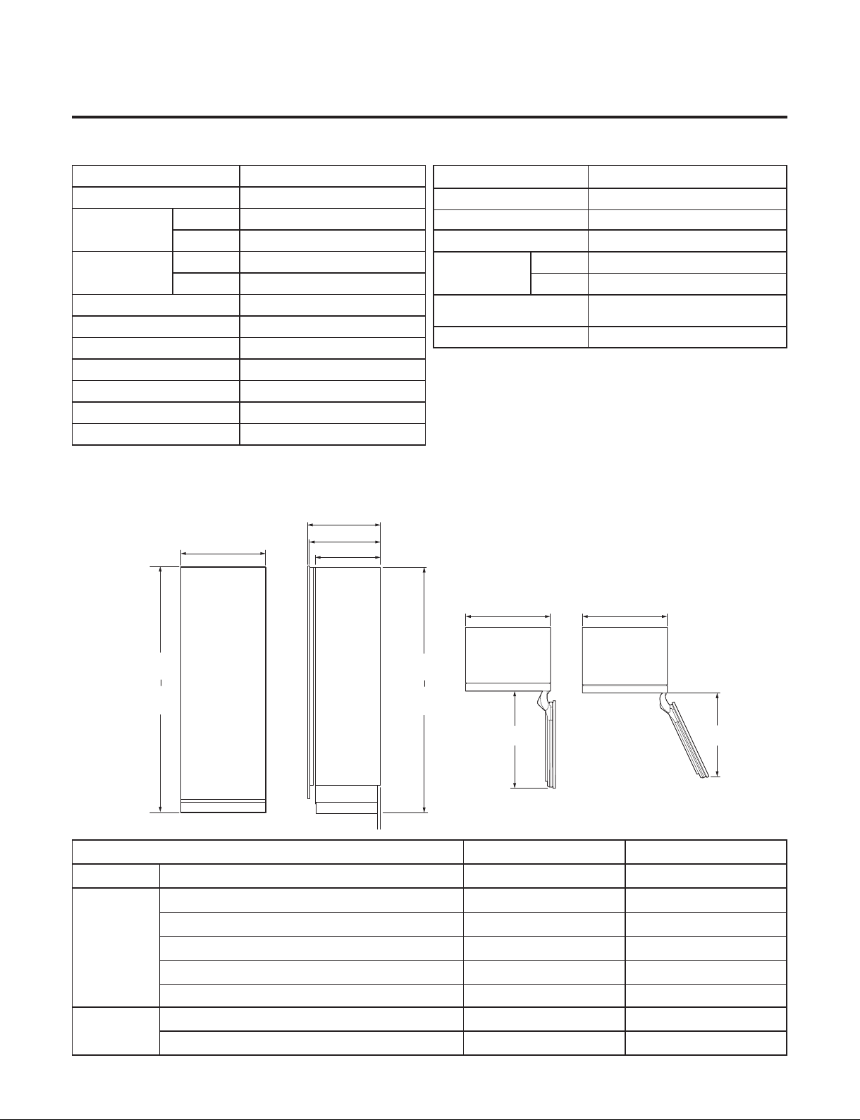
● DIMENSIONS
ITEMS SPECIFICATIONS
DOOR DESIGN Side Rounded
DIMENSIONS
18W
17 1/2 x 23 7/8 x 83 1/2 (W X D X H)
24W
23 4/3 x 23 7/8 x 83 1/2 (W X D X H)
NET WEIGHT
18W 139kg (306lb)
24W 162kg (357lb)
COOLING SYSTE M Fan Cooling
TEMPERATURE CONTROL Micom Control
DEFROSTING SYSTEM
Natural Defrost System
DOOR FINISH GI
HANDLE TYPE Bar
INNER CASE Aluminum
INSULATION Polyurethane Foam
Description SKSCW181RP SKSCW241RP
Width Width (A) 17 1/2"(445mm) 23 3/4"(603mm)
Depth
Depth with 3/4"(19mm) Door panel (B) 24 3/4"(629mm) 24 3/4"(629mm)
Depth with door (No panel) ( C ) 23 7/8"(607mm) 23 7/8"(607mm)
Cabinet depth without Door (D) 22"(558mm) 22"(558mm)
Door Open 90º (E) 21 7/8"(556m) 28 1/8"(713mm)
Door Open 115º (F) 20 1/2"(520mm) 26 1/2"(659mm)
Height
Min (G) 83 1/2"(2121mm) 83 1/2"(2121mm)
Max (H) 84 1/2"(2146mm) 84 1/2"(2146mm)
ITEMS SPECIFICATIONS
COMPRESSOR Linear
EVAPORATOR Rollbond Type
CONDENSER Micro channel Condenser (Al)
REFRIGERANT
18W R 600a (42g)
24W R 600a (44g)
LUBRICATING OIL
Mineral / Freol Alpha 3G (3cst)
(120cc)
LAMP LED Module
(E)
DOOR OPEN 90˚
FRONT VIEW
SIDE VIEW
TOP VIEWS
DOOR OPEN 115˚
(F)
(A)
(A)
(A)
(B)
(C)
(D)
(G)
min.
(H)
max.
(G)
min.
(H)
max.
- 8 -
Copyright © 2018-2019 SIGNATURE KITCHEN SUITE.
All rights reserved. Only training and service purposes.
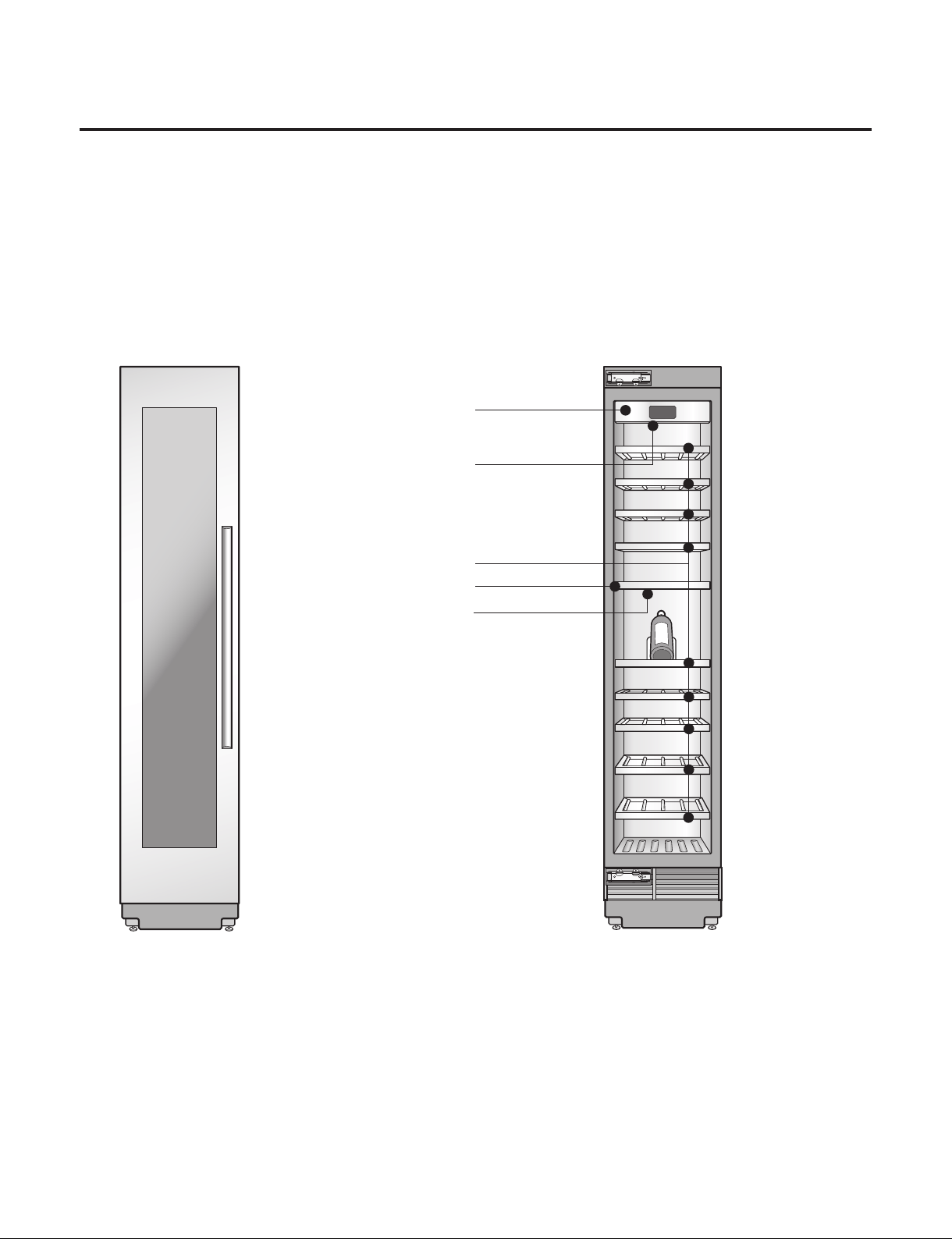
Control Panel
LED Interior
Lighting
Storage Rack
Zone Divider
LED Interior
Lighting
● Parts
MODEL : SKSCW181RP
- 9 -
Copyright © 2018-2019 SIGNATURE KITCHEN SUITE.
All rights reserved. Only training and service purposes.
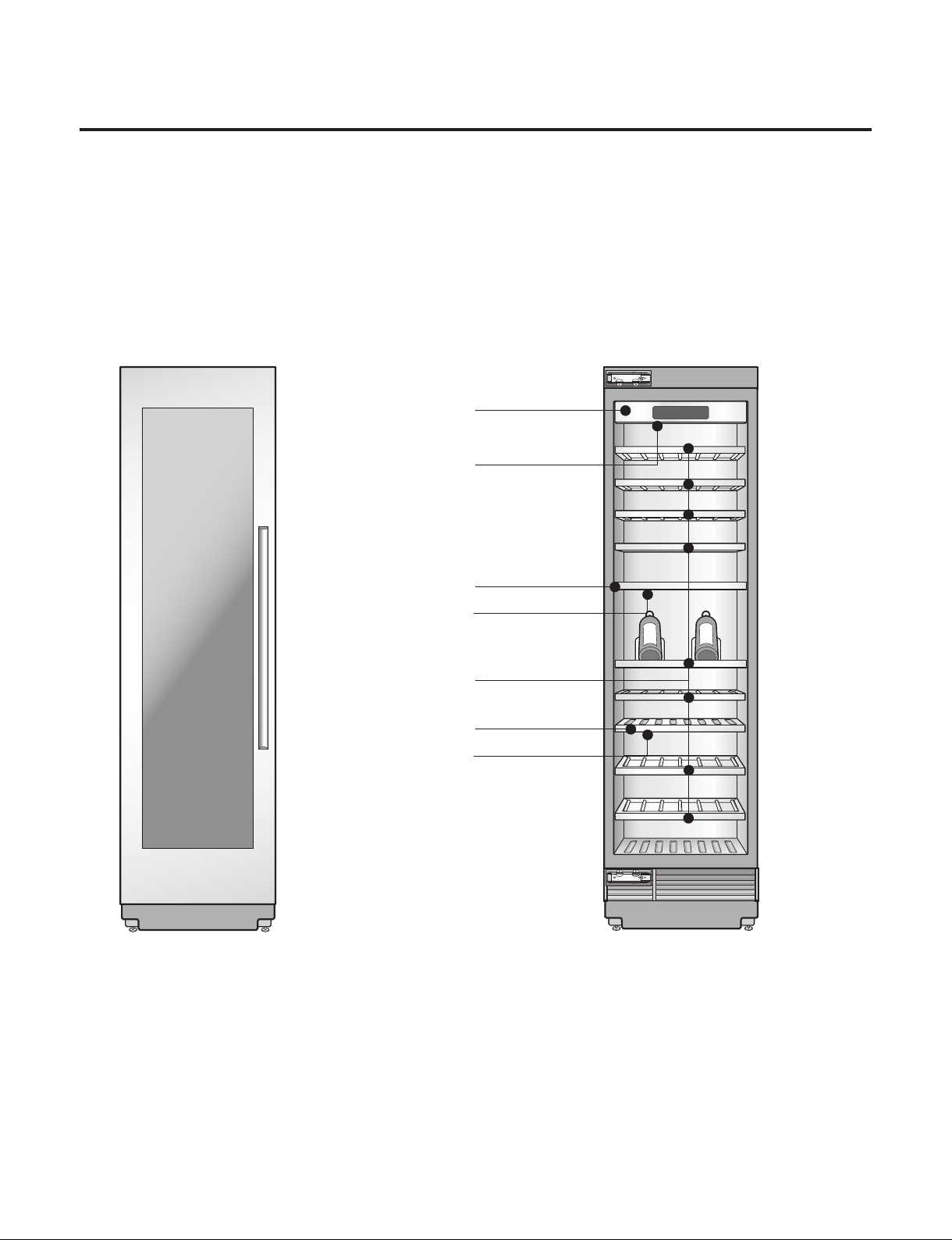
Control Panel
LED Interior
Lighting
Storage Rack
Zone Divider
LED Interior
Lighting
Zone Divider
LED Interior
Lighting
● Parts
MODEL : SKSCW241RP
- 10 -
Copyright © 2018-2019 SIGNATURE KITCHEN SUITE.
All rights reserved. Only training and service purposes.
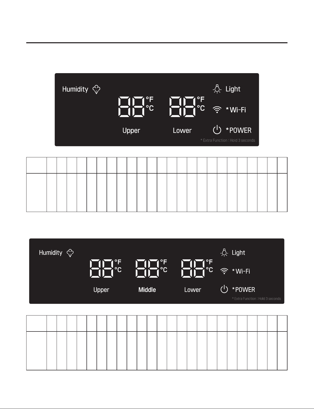
5. MICOM FUNCTION
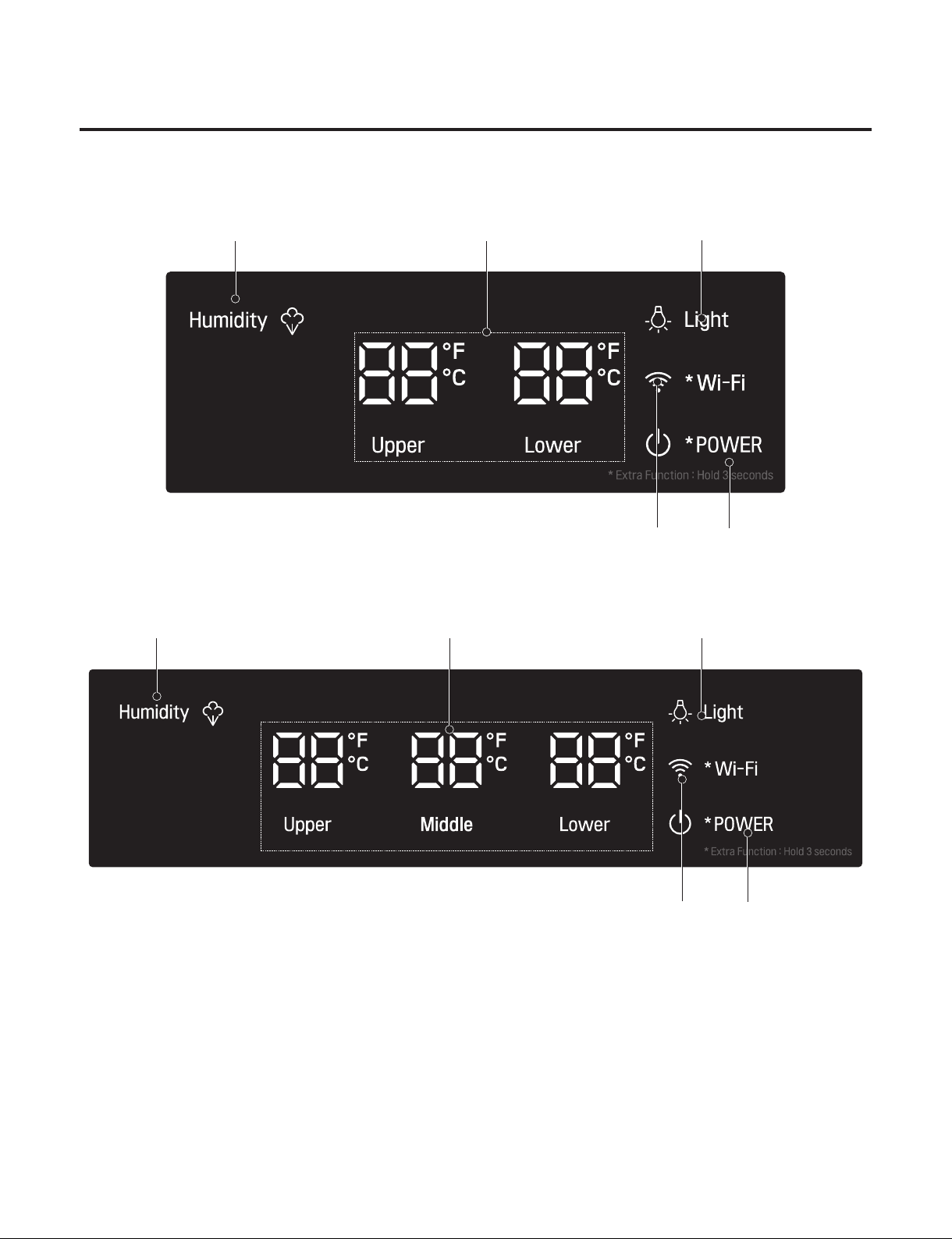
● Operating panel drawing (Applied display is different for each model)
- MODEL : SKSCW181RP
- MODEL : SKSCW241RP
NOTCH
10 11 12 13 14 15 16 17 18 19 20 21 22 23 24 1 2 3 4 5 6 7 8 9
Upper/
Lower
Set
Temper
ature
55˚F 54˚F 53˚F 52˚F 51˚F 50˚F 49˚F 48˚F 47˚F 46˚F 45˚F 44˚F 43˚F 42˚F 41˚F 64˚F 63˚F 62˚F 61˚F 60˚F 59˚F 58˚F 57˚F 56˚F
NOTCH
10 11 12 13 14 15 16 17 18 19 20 21 22 23 24 1 2 3 4 5 6 7 8 9
Upper/
Middle
Lower/
Set
Temper
ature
55˚F 54˚F 53˚F 52˚F 51˚F 50˚F 49˚F 48˚F 47˚F 46˚F 45˚F 44˚F 43˚F 42˚F 41˚F 64˚F 63˚F 62˚F 61˚F 60˚F 59˚F 58˚F 57˚F 56˚F
- 11 -
Copyright © 2018-2019 SIGNATURE KITCHEN SUITE.
All rights reserved. Only training and service purposes.
- Model : SKSCW241RP
● Description of Function
- MODEL : SKSCW181RP
Temperature setting
: Indicates the set temperature of the Refrigerator compartment in Celsius or Fahrenheit.
Humidity
: The FAN motor for humidity in the refrigerator will be activated or deactivated whenever pressing the button.
Light
: Inner LED turns on/off whenever pressing the button
Wi-Fi
: The Wi-Fi Icon is blinked when press and hold the button for 3 sec. And then,
- Wi-Fi Connecting : Wi-Fi Icon turns on.
- Wi-Fi Disconnecting : Wi-Fi Icon turns off after 3 min.
Power
: The Power Icon always on. If the power button is pressed and hold for 3 sec., it turns off.
- 12 -
Copyright © 2018-2019 SIGNATURE KITCHEN SUITE.
All rights reserved. Only training and service purposes.
6. TROUBLE SHOOTING
Open the PCBA Cover
Check the LED blinking times
(Refer to the next chapter for LED blinking and actions.)
If the Comp is normal,
the LED does not blink.
Open the PCBA Cover
Check the LED blinking times
(Refer to the next chapter for LED blinking and actions.)
If the Comp is normal,
the LED does not blink.
1. COMP Bad Operation
- 13 -
Copyright © 2018-2019 SIGNATURE KITCHEN SUITE.
All rights reserved. Only training and service purposes.
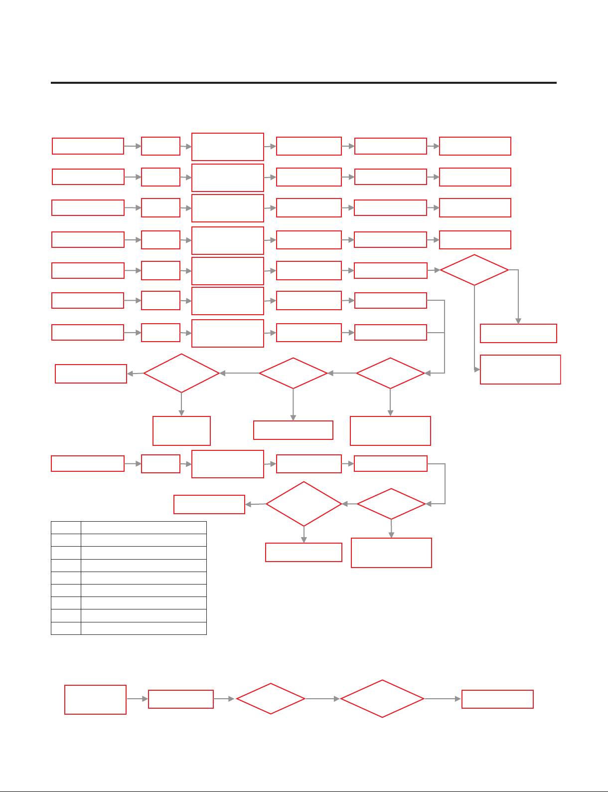
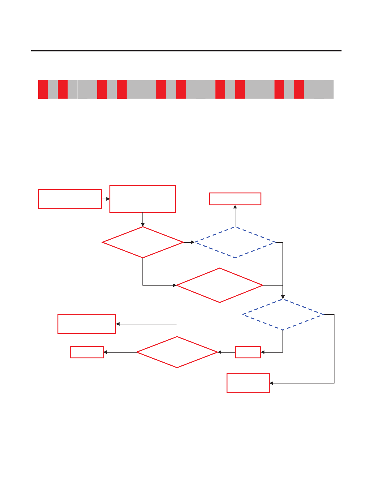
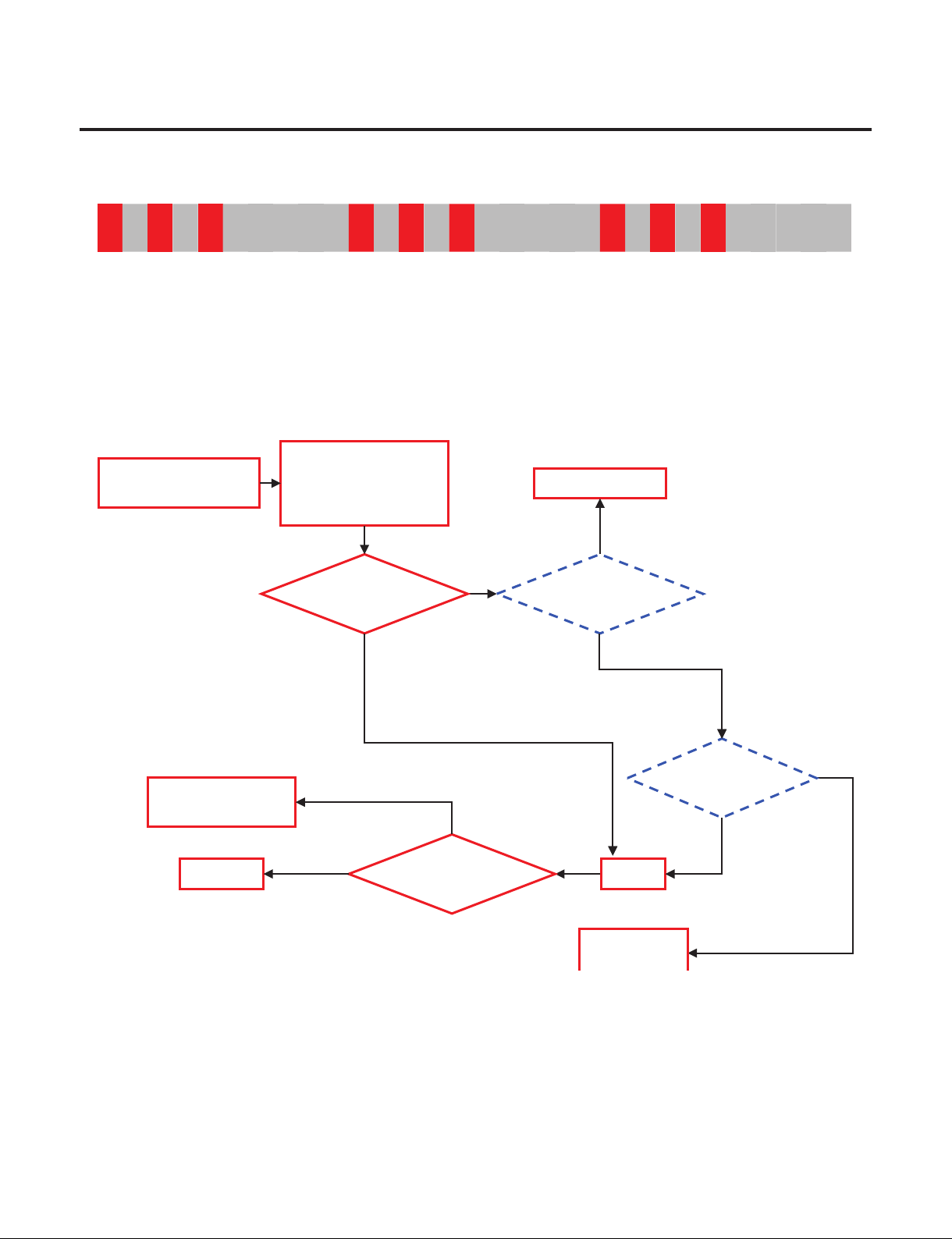
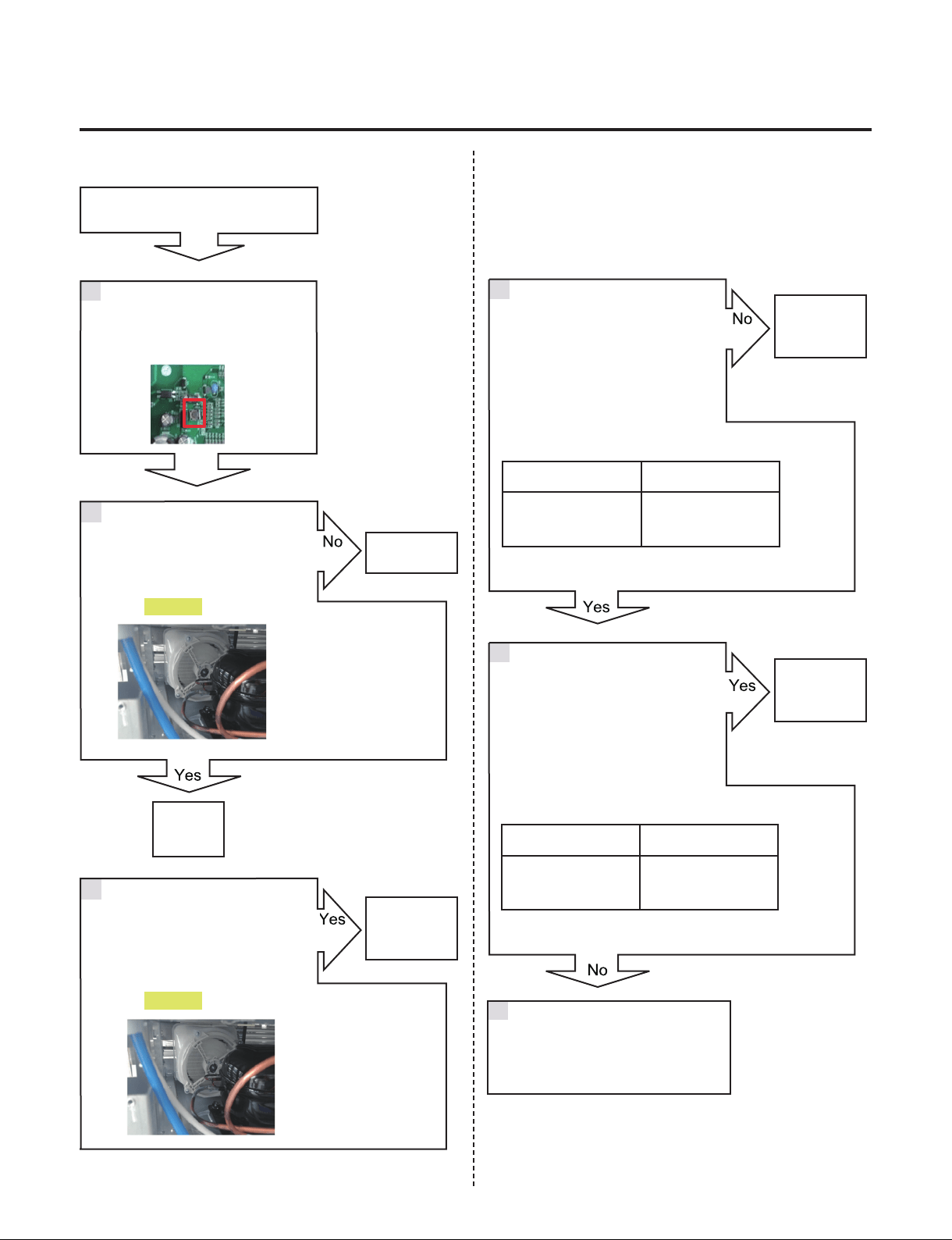
2. Simple Check Flow Chart
- Not Cooling (LED Blinking)
- Not Cooling (LED No Blinking)
Check Comp.
Y
N
PCBA
Output
> 60V?
N
N
Y
LED 7 Blinks
LED 2 Blinks
LED 1 Blinks
Replace PCB
Comp.
Action?
Replace PCB
Y
LED6 Blinks
Comp.
Action?
Harness
wiring?
Y
Repair Harness
N
LED 8 Blinks
Replace PCBReset
LED 7 Blinks
LED 1 Blinks
LED 2 Blinks
LED 6 Blinks
LED 8 Blinks
LED 3 Blinks LED 3 Blinks
LED 5 Blinks
Comp.
Action?
LED 5 Blinks
Check C
omp.
Check Comp.
Check
Cycle leakage
Cycle
Cycle leakage
Check
Cycle leakage
About 5min
About 5min
About 5min
About 5min
About 5min
About 5min
About 5min
LED 4 Blinks
Replace PCB
LED 4 Blinks
About 5min
Reset
Reset
Reset
Reset
Reset
Reset
Reset
Test Mode
1 Input
Test Mode
1 Input
Test Mode
1 Input
Test Mode
1 Input
Test Mode
1 Input
Test Mode
1 Input
Test Mode
1 Input
Test Mode
1 Input
PCBA
Output
> 60V
Replace PCB
Replace PCB
Y
N
Y
N
LED Trip Information
1 Current/Voltage Sensing Error
2 Over Stroke
3 Comp Connection Error
4 Over Voltage Error
5 Comp Lock Error
6 Over Current Error
7 IPM Error
8 Communication Error
Comp.
Action?
PCBA
Output
> 60V
Replace PCB
N
N
Test Mode
1 Input
About 5min
- 14 -
Copyright © 2018-2019 SIGNATURE KITCHEN SUITE.
All rights reserved. Only training and service purposes.
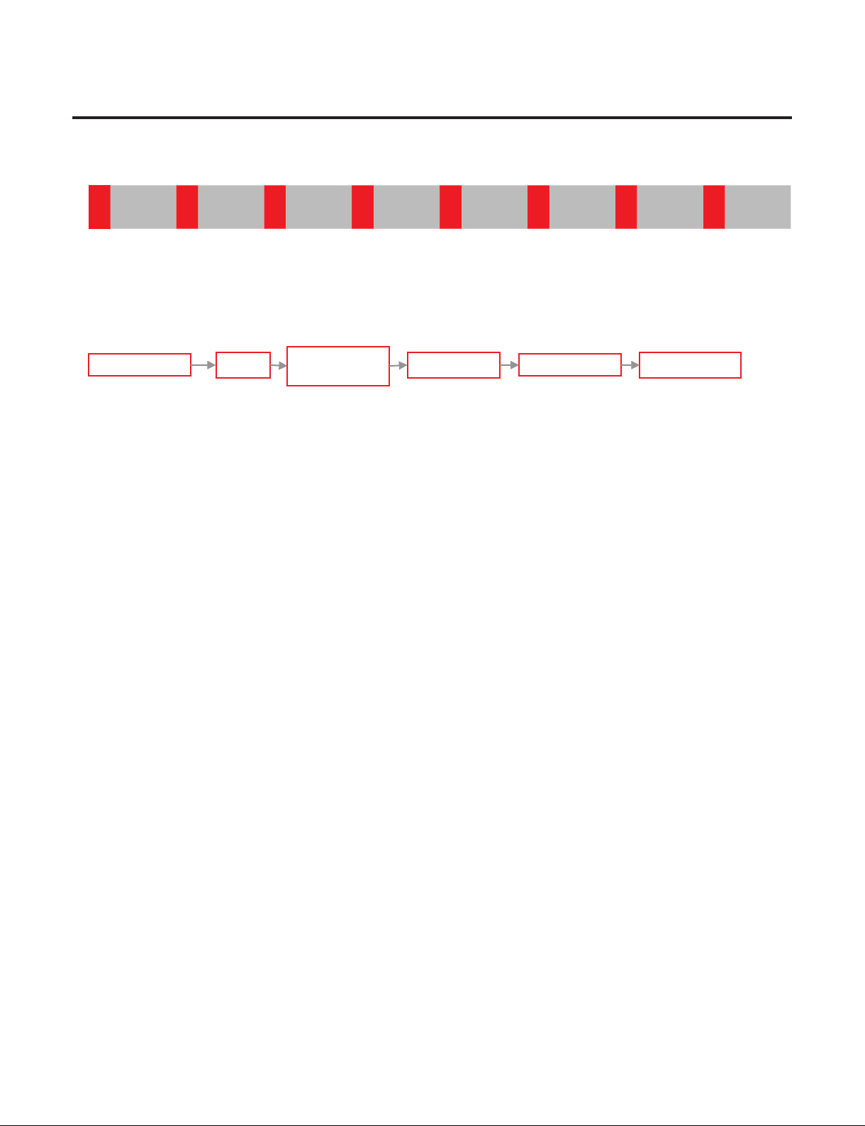
3. What to do per LED Blinking and Trip protection logic
(1) FCT0 Trip and LED Blinking 1 time (FCT0 Fault)
→ Purpose : To detect the compressor voltage and current sensing error.
→ Restart every 30 seconds after compressor off.
Blink BlinkOFF OFF
LED 1 Blinks
Replace PCB
LED 1 Blinks
About 5minReset
Test Mode
1 Input
- 15 -
Copyright © 2018-2019 SIGNATURE KITCHEN SUITE.
All rights reserved. Only training and service purposes.
3. What to do per LED Blinking and Trip protection logic
(2) Stroke Trip and LED Blinking 2 times (Stroke Trip)
→ Purpose : Protection piston crash by abnormally large Stroke.
→ Case 1. Do not operate Comp.
: Harness connection failure between the PCB, Comp, Capacitor.
→ Case 2. Do operate Comp. intermittently
: Condenser Fan or Freezer Fan Error.
System Error like water-clogging, capillary-clogging, refrigerant-leakage
→ Logic: After the Comp. Off every 1 minute restart Comp.
Blink Blink Blink BlinkOFF OFF
Y
Y
Y
Check
the Protection Logic
Check Stroke or
LED Blinking 2 times
(Stroke Trip)
Do not operate
Comp.?
Y
N
Compressor is operate
intermittently
Check Comp.
Replace
Compressor
N
Reset
Stroke Trip
occur?
Check the
leakage and cycle
Y
Recheck
Check
Harness connection
Repair Harness
N
N
- 16 -
Copyright © 2018-2019 SIGNATURE KITCHEN SUITE.
All rights reserved. Only training and service purposes.
3. What to do per LED Blinking and Trip protection logic
(3) No Connect Trip and LED Blinking 3 times (No Connection Trip)
→ Purpose : Prevention Over-Voltage and Over-Current by detecting connection error check.
→ Harness connection failure between PCB, Comp, Capacitor.
Comp. insulation breakdown.
→ Logic : After the Comp. Off every 40 seconds restart Comp.
Blink Blink Blink BlinkBlinkBlink OFF OFF
Y
Y
Check
the Protection Logic
Check
No Connect or
LED blinking 3 times
(No Connect Trip)
Do not operate
Comp.?
Y
N
Check Comp.
Replace
Compressor
N
Reset
No Connect Trip
occur?
Replace PCB
Y
Recheck
Check
Harness connection
Repair Harness
N
N
- 17 -
Copyright © 2018-2019 SIGNATURE KITCHEN SUITE.
All rights reserved. Only training and service purposes.
3. What to do per LED Blinking and Trip protection logic
(4) Over Voltage Trip and LED Blinking 4 times (Over Voltage Trip)
→ Purpose : Protection the PCB by Over Voltage
→ Cause : Applying the Over Voltage to DC Link(450VDC or higher)
→ Logic: Restart every 90 seconds after compressor off.
Blink Blink Blink Blink BlinkBlinkBlink Blink OFF OFF
LED 4 Blinks
Replace PCB
LED 4 Blinks
About 5minReset
Test Mode
1 Input

- 18 -
Copyright © 2018-2019 SIGNATURE KITCHEN SUITE.
All rights reserved. Only training and service purposes.
3. What to do per LED Blinking and Trip protection logic
(5) L/Piston Trip and LED Blinking 5 times (Locked Piston)
→ Purpose : Detect locked piston.
→ Cause : Oil shortage of the cylinder, Cylinder or Piston damage, clogging the discharge,
Comp. internal debris.
→ Logic : After the Comp. Off every 2 min 30 seconds restart Comp.
Blink Blink BlinkBlink Blink OFF
Check
the Protection Logic
Check the L/Piston or
LED blinking 5 times
(Locked Piston Trip)
Do not operate
Comp.?
Recheck
Reset
Do not operate
Comp.?
N
Y
Replace
Compressor
Clogging the Cycle?
N
Y
Repair
Sealed system
- 19 -
Copyright © 2018-2019 SIGNATURE KITCHEN SUITE.
All rights reserved. Only training and service purposes.
3. What to do per LED Blinking and Trip protection logic
(6) Current Trip and LED Blinking 6 times (Current Trip)
→ Purpose : Protection Over-Current(Over-Load)
→ Cause : Abnormally ambient temperature(Over 43°C), Abnormally conditions like
Shield machine room etc. Condenser Fan failure, Comp. failure, PCB failure
(IPM breakdown)
Oil shortage of the cylinder, Cylinder or Piston damage, clogging the discharge,
Comp. internal debris.
→ Logic : After the Comp. Off every 6 minutes restart Comp.
Blink Blink Blink BlinkBlinkBlink OFF
Check
the Protection Logic
Check the Current or
LED blinking 6 times
(Current Trip)
Compressor is operate
intermittently
Y
Check the
Compressor failure
Replace
Compressor
N
Reset
Y
Current trip
occur?
Check the
leakage and cycle
Recheck
Check the
PCB output
Y
Replace PCB
N
N
N
N
Y
Replace
Compressor
Repair
Sealed system
Y
Do not operate
Comp.?
Clogging the Cycle?
N
Y

- 20 -
Copyright © 2018-2019 SIGNATURE KITCHEN SUITE.
All rights reserved. Only training and service purposes.
3. What to do per LED Blinking and Trip protection logic
(7) IPM Fault Trip and LED Blinking 7 times (IPM Fault)
→ Purpose : Protection Over-Current by failure IPM(IPM short)
→ Cause : IPM Short and failure
→ Logic : After the Comp. Off every 20 seconds restart Comp.
Blink Blink Blink
Blink Blink
BlinkBlink OFF
LED 7 Blinks
Replace PCB
LED 7 Blinks
About 5minReset
Test Mode
1 Input
- 21 -
Copyright © 2018-2019 SIGNATURE KITCHEN SUITE.
All rights reserved. Only training and service purposes.
3. What to do per LED Blinking and Trip protection logic
(8) Comp Tx Error Trip and LED Blinking 8 times (Communication Error)
→ Purpose : Detection communication error with the Micom of the refrigerator control.
→ Cause : Communication Error
→ Logic : Only LED blinking without the Comp. Off
(Comp. is operate command before communication error)
Blink Blink Blink
Blink Blink Blink
BlinkBlink OFF
LED 8 Blinks
Replace PCBReset
LED 8 Blinks
About 5min
Test Mode
1 Input
- 22 -
Copyright © 2018-2019 SIGNATURE KITCHEN SUITE.
All rights reserved. Only training and service purposes.
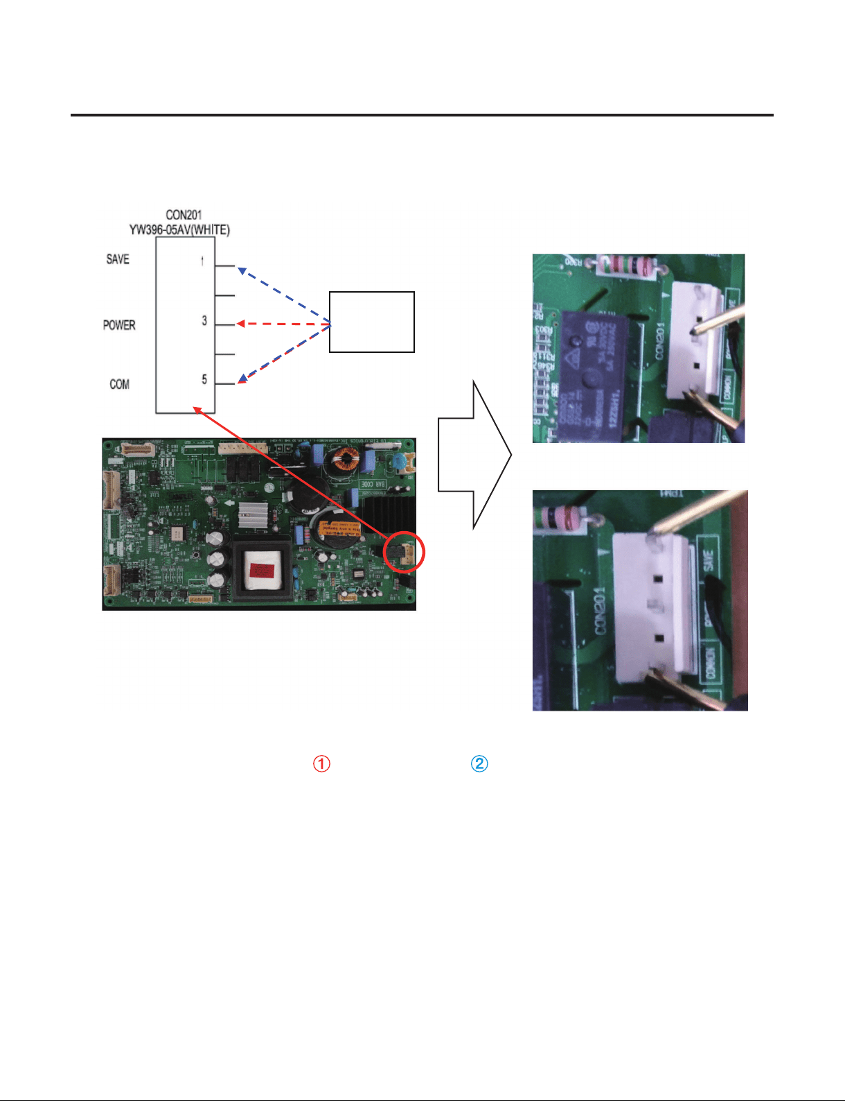
4. Check the PCB Output
→ Check output voltage from PCB to Compressor.
→ To judge whether there is any issue with the PCB operation, check the PCB output voltage.
Normal: Voltage 80[V] or higher output at (COMMON,POWER) or (COMMOM,SAVE)
IPM Output check
SAMPLE
SAMPLE
Multi
Tester
①
①
②
②
- 23 -
Copyright © 2018-2019 SIGNATURE KITCHEN SUITE.
All rights reserved. Only training and service purposes.
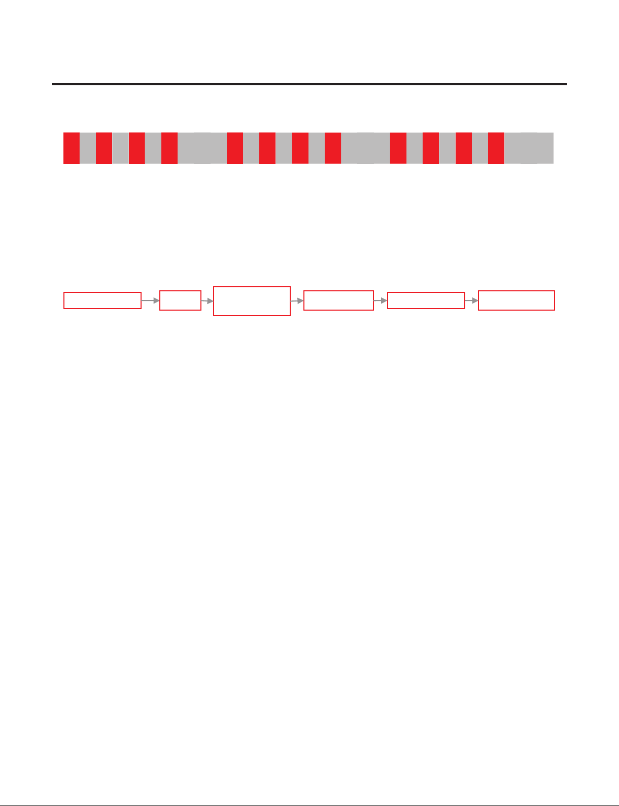
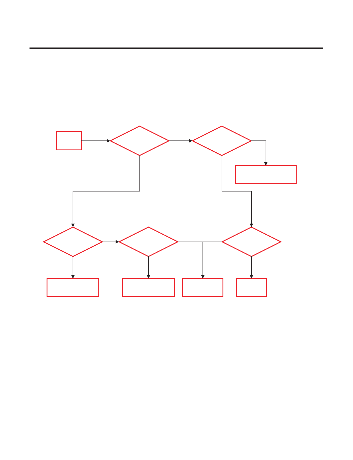
5. Check the Compressor & Harness
(1) Check the Harness connection → Step 1. Power off.
(2) Check the Compressor Step 2. Check the Resistance(point A)
Step 3. Check the Harness(INF ohm).
Step 4. Check the Resistance(point B)
Step 5. Check the Resistance(point D)
Power
off
Check the
Resistance
(point A)
Harness Connection
OK
A~B
Connection error
Check
the Resistance
(point B)
Check
the Resistance
(point D)
Replace
Compressor
B~D
Connection error
Check
the Harness
Y
N
N
Y
Y
Y
N
N
Check
Comp.
terminal
Harness
failure
Y
N
Y
- 24 -
Copyright © 2018-2019 SIGNATURE KITCHEN SUITE.
All rights reserved. Only training and service purposes.
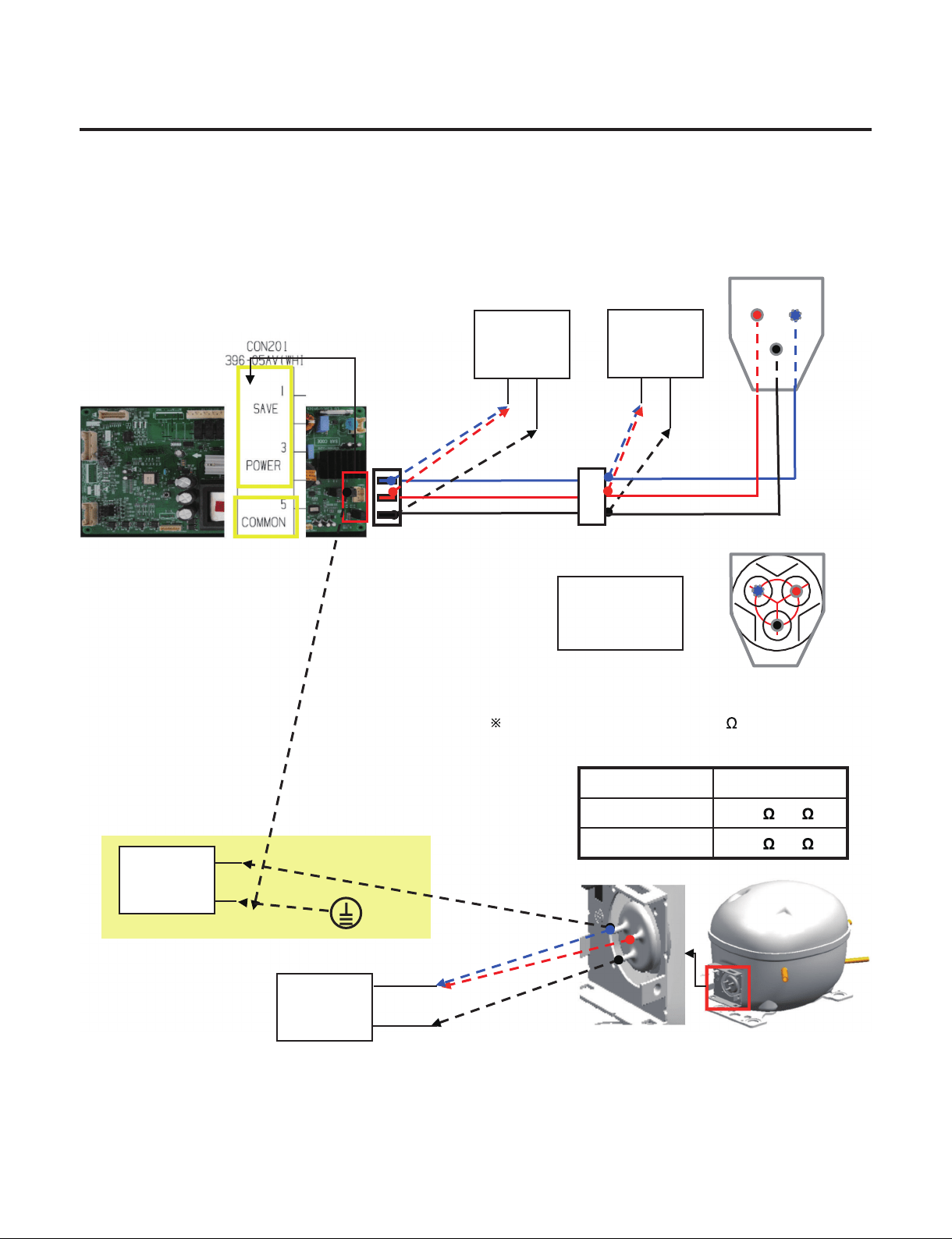
5. Check the Compressor & Harness
→ Comp Terminal resistance measurement (Power & Common, Save & Common)
→ Check the broken-down insulation : Comp. Save - Earth resistance measurement
Sa: Save
Po: Power
Co: Common
Point A
Point B
Point D
Multi
Tester
Multi
Tester
①
②
①
②
FMA102NAMA
Co
Sa
Po
The resistance can differ by few depending on
the surrounding temperature or operating condition.
Mode Resistance
Power(①) 14 ~17
Save(②) 20 ~23
Check insulation break-down
Multi
Tester
Multi
Tester
Earth
②
①

- 25 -
Copyright © 2018-2019 SIGNATURE KITCHEN SUITE.
All rights reserved. Only training and service purposes.
7. TROUBLE SHOOTING WITH ERROR DISPLAY
7-1. Error Code
18 Wine 24 Wine Failure Details
1
Abnormal Internal
Temp. Sensor
ES1/ES2 ES1/ES2/ES3
Internal Temp. Sensor Short or Open
Circuit
2
Abnormal Defrost
Sensor
Ed1/Ed2 Ed1/Ed2/Ed3 Defrost Sensor Short or Open Circuit
3
Abnormal Ambient
Sensor
E rt E rt
Ambient Sensor Short or Open
Circuit
4 Abnormal Wi-Fi E Od E Od
Communication Short or Open Circuit
(Display ↔ Wi-Fi Module)
5
Abnormal Internal Fan
Motor
EF1/EF2 EF1/EF2/EF3
There No Signal Of BLDC Fan Motor
More Then 65 Seconds In Operation
Of Fan Motor (BLDC Motor
Connection, Drive IC Or TR Defect)
6
Abnormal Condenser
Fan Motor
E CF E CF
7
Abnormal
Communication
E CO E CO
Communication Short ior Open
Circuit (Display ↔ Main PCB)
18 Wine
24 Wine
- 26 -
Copyright © 2018-2019 SIGNATURE KITCHEN SUITE.
All rights reserved. Only training and service purposes.
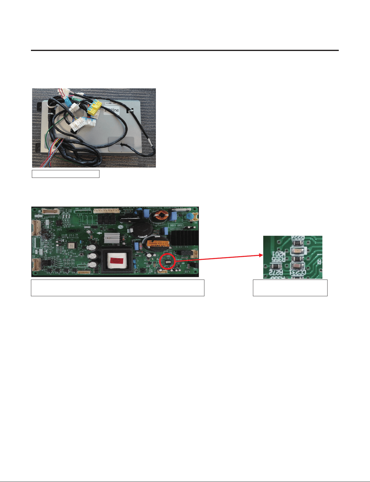
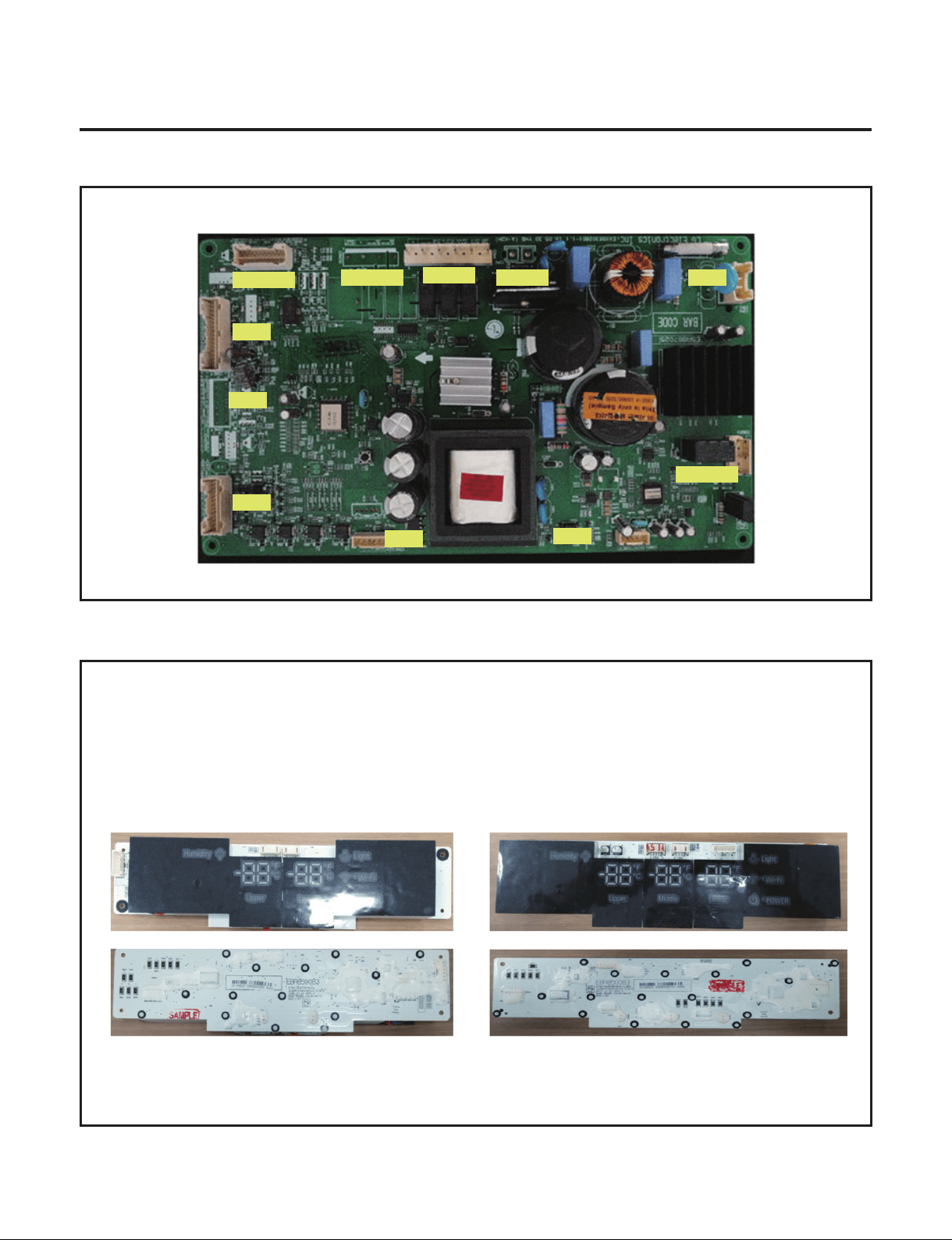
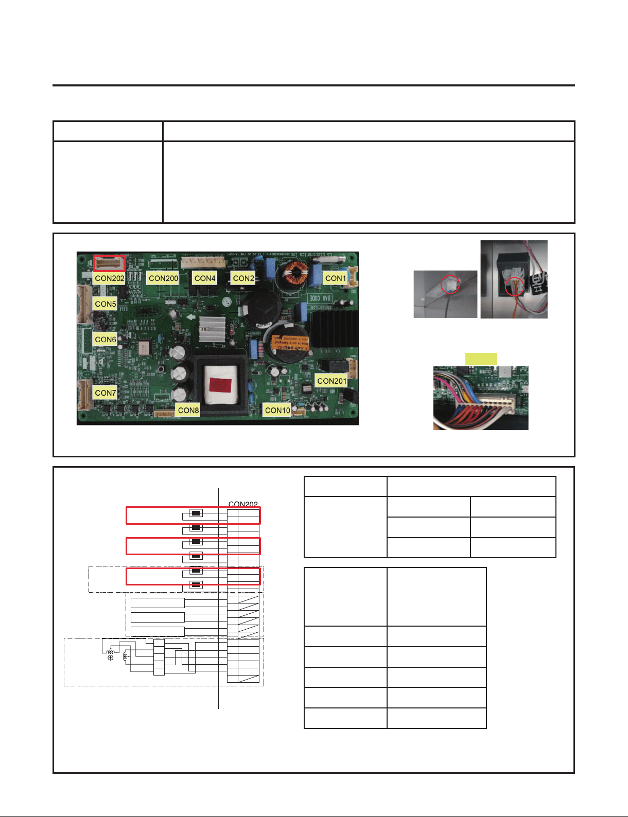
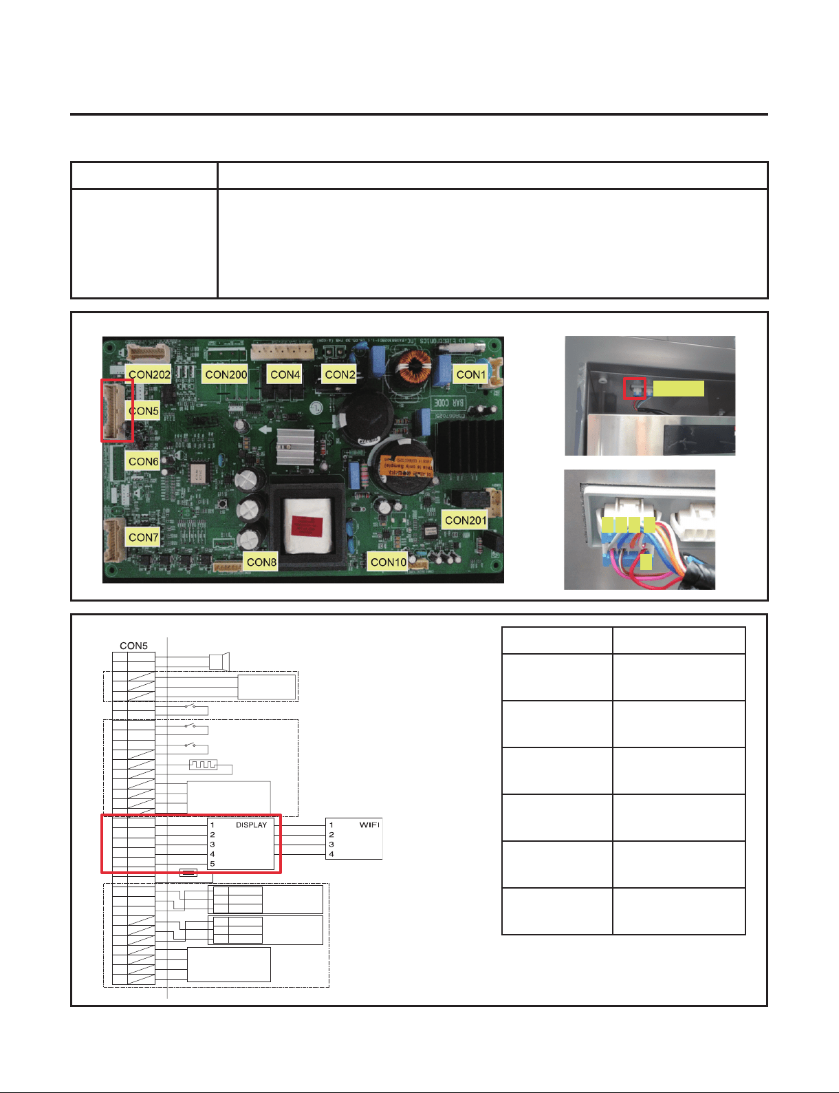
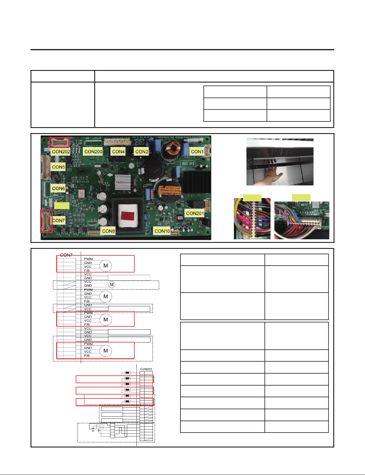
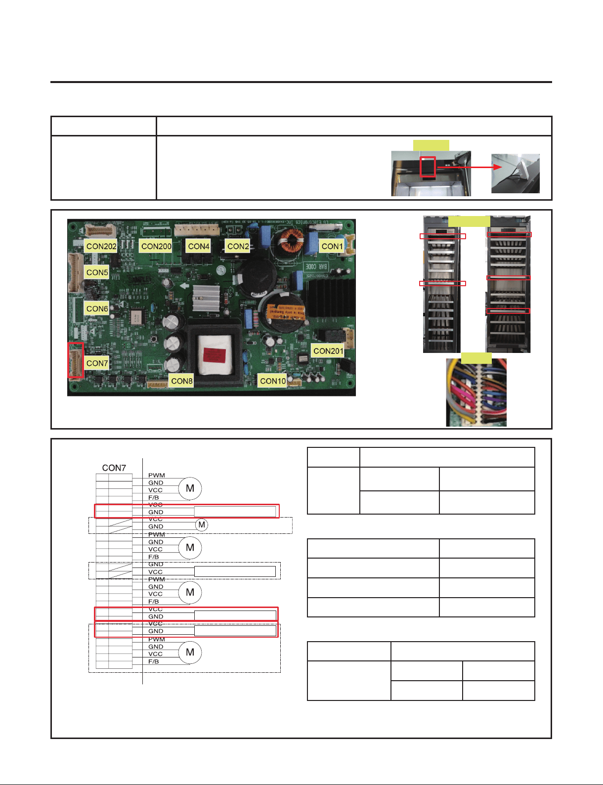
7. TROUBLE SHOOTING WITH ERROR DISPLAY
7-2. PCB Picture - Main PCB
( P/N : EBR867025)
7-3. PCB Picture - Display PCB
P/N : EBR850083
EBR852442
EBR852442
EBR852443
CON202
CON200
CON4
CON2 CON1
CON5
CON6
CON7
CON8
CON10
CON201
18inch 24inch
- 27 -
Copyright © 2018-2019 SIGNATURE KITCHEN SUITE.
All rights reserved. Only training and service purposes.
CON202
WH
WH
BK
BK
RD
RD
BO
BO
BL
BL
SB
GY/RD
WH/BK
YL
PK
BO/BL
BO/BL
1
3
5
7
9
11
13
15
17
19
21
23
2
4
6
8
10
12
14
16
18
20
22
24
VCC
GND
VCC
GND
VCC
GND
COM
A
B
B-
A-
1
2
5
6
3.4
3WAY/4WAY
VALVE
W1 SENSOR
W1 DEFROSTING SENSOR
W2 SENSOR
W2 DEFROSTING SENSOR
W3 SENSOR
W3 DEFROSTING SENSOR
W1 LED LIGHT
W2 LED LIGHT
W3 LED LIGHT
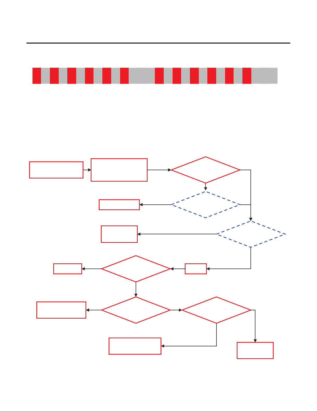
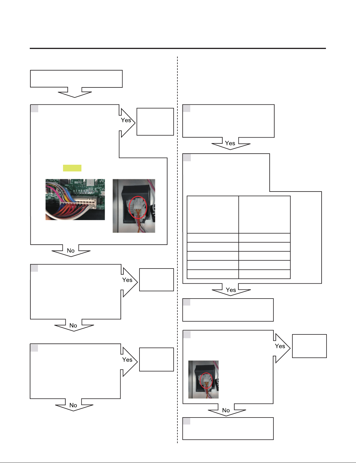
7-4. Refrigerator Sensor Error (S1/S2/S3)
Symptom Check Point
1. S1/S2/S3(Option) 1. Check for a loose connection
2. Check Sensor Resistance
Resistance [Ω]
CON202
[S1]1 pin&3pin
[S2]9 pin&11pin
[S3]17 pin&19pin
Short 0
Open OFF
Other Normal
CON202
[S1]1 pin&3pin
[S2]9 pin&11pin
[S3]17 pin&19pin
Resistance [Ω]
23ºF / -5ºC 38k
32ºF / 0ºC 30k
41ºF / 5ºC 24k
50ºF / 10ºC 19.5k
59ºF / 15ºC 16k
W1 Sensor W2 Sensor
W3 Sensor
- 28 -
Copyright © 2018-2019 SIGNATURE KITCHEN SUITE.
All rights reserved. Only training and service purposes.
- 28 -
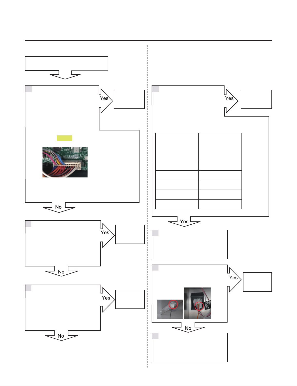
RRefrigerator Sensor Error (S1/S2/S3)
Is the Connector disconnected
or loose between Main PCB and
sensor?
Check the Sensor resistance.
Is resistance 0Ω (Sensor short)?
Check the Sensor resistance.
Is resistance OFF (Sensor open)?
Change the
Sensor
Go to 6
Explain to customer
Check the sensor connection.
Is the sensor connection normal?
Reconnect or repair
the connector
Reconnect
or repair the
connector
Change the
Sensor
Replace the
refrigerator
CON202
[S1]1 pin&3pin
[S2]9 pin&11pin
[S3]17 pin&19pin
Resistance [Ω]
23ºF / -5ºC 38k
32ºF / 0ºC 30k
41ºF / 5ºC 24k
50ºF / 10ºC 19.5k
59ºF / 15ºC 16k
Check the Temperature and
resistance refer to the table.
No problem?
CON202
1 4
2
3
5
6
7
- 29 -
Copyright © 2018-2019 SIGNATURE KITCHEN SUITE.
All rights reserved. Only training and service purposes.
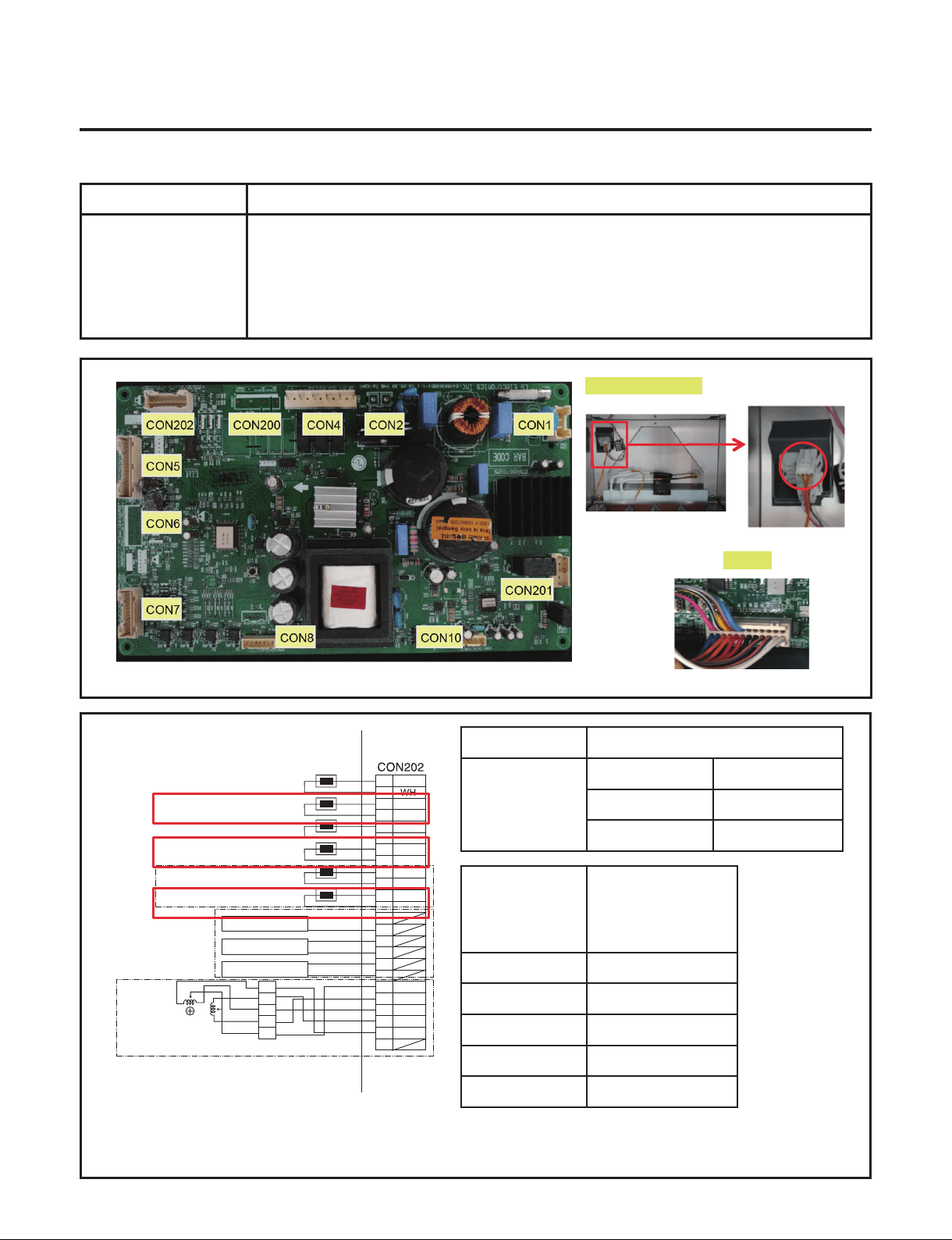
7-5. Defrost Sensor Error (d1/d2/d3)
Symptom Check Point
1. d1/d2/d3(Option) 1. Check for a loose connection
2. Check Sensor Resistance
Resistance [Ω]
CON202
[d1]5 pin&7pin
[d2]13 pin&15pin
[d3]21 pin&23pin
Short 0
Open OFF
Other Normal
CON202
[d1]5 pin&7pin
[d2]13 pin&15pin
[d3]21 pin&23pin
Resistance [Ω]
23ºF / -5ºC 38k
32ºF / 0ºC 30k
41ºF / 5ºC 24k
50ºF / 10ºC 19.5k
59ºF / 15ºC 16k
CON202
Defrost Controller
WH
WH
BK
BK
RD
RD
BO
BO
BL
BL
SB
GY/RD
WH/BK
YL
PK
BO/BL
BO/BL
1
3
5
7
9
11
13
15
17
19
21
23
2
4
6
8
10
12
14
16
18
20
22
24
VCC
GND
VCC
GND
VCC
GND
COM
A
B
B-
A-
1
2
5
6
3.4
3WAY/4WAY
VALVE
W1 SENSOR
W1 DEFROSTING SENSOR
W2 SENSOR
W2 DEFROSTING SENSOR
W3 SENSOR
W3 DEFROSTING SENSOR
W1 LED LIGHT
W2 LED LIGHT
W3 LED LIGHT
- 30 -
Copyright © 2018-2019 SIGNATURE KITCHEN SUITE.
All rights reserved. Only training and service purposes.
Defrost Sensor Error (d1/d2/d3)
Is the Connector disconnected
or loose between Main PCB,
Defrost controller and Sensor?
Check the Sensor resistance.
Is resistance 0Ω (Sensor short)?
Check the Sensor resistance.
Is resistance OFF (Sensor open)?
Change the
Sensor
Go to 7
Check the Sensor resistance.
Is resistance normal?
Explain to customer
Reconnect
or repair the
connector
CON202
1
CON7
CON202
[d1]5 pin&7pin
[d2]13 pin&15pin
[d3]21 pin&23pin
Resistance [Ω]
23ºF / -5ºC 38k
32ºF / 0ºC 30k
41ºF / 5ºC 24k
50ºF / 10ºC 19.5k
59ºF / 15ºC 16k
Check the Temperature and
resistance refer to the table.
No problem?
5
2
3
4
6
Check the sensor connection.
Is the sensor connection normal?
Replace the
refrigerator
7
Reconnect or repair the connector
8
Orange & Orange
- 31 -
Copyright © 2018-2019 SIGNATURE KITCHEN SUITE.
All rights reserved. Only training and service purposes.
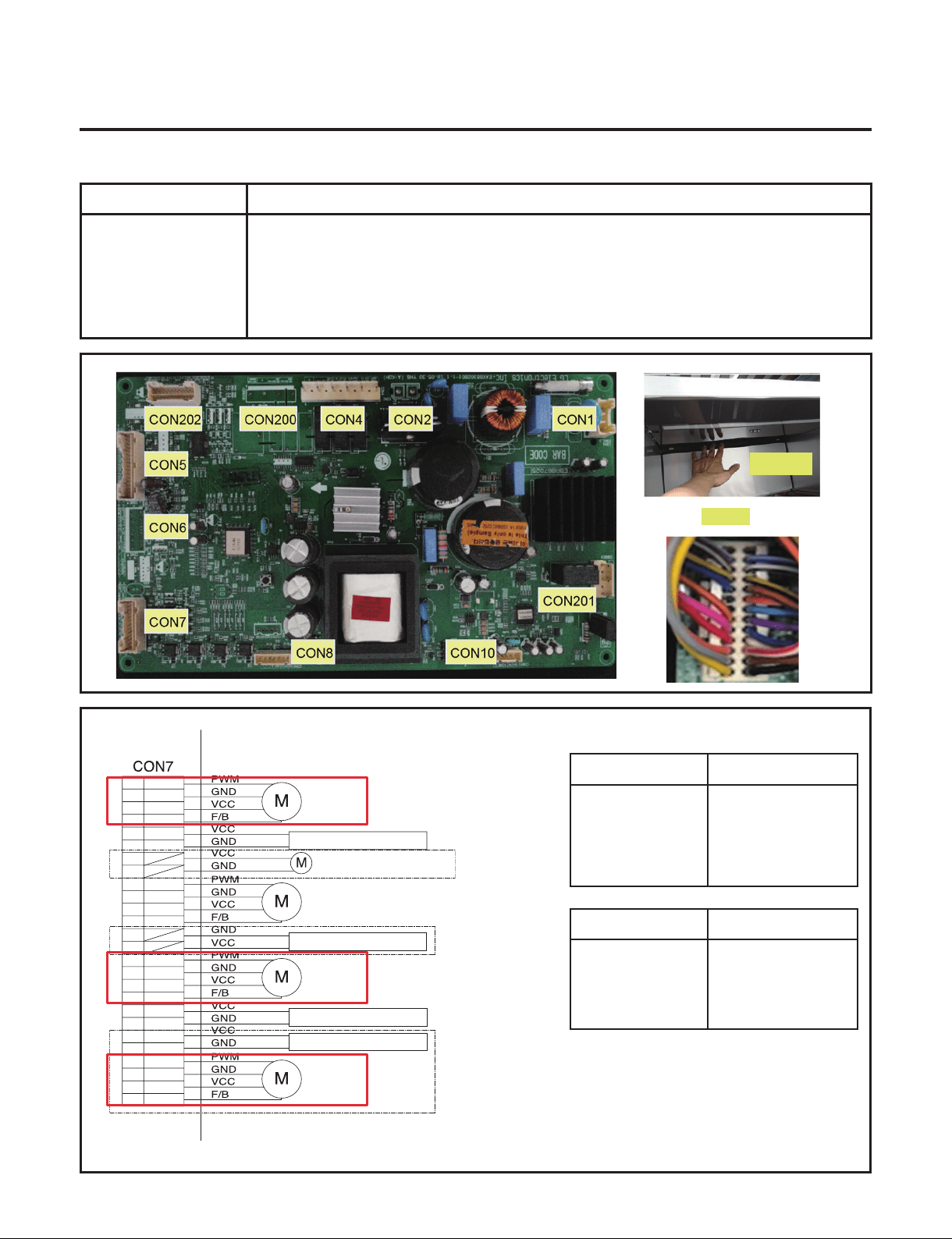
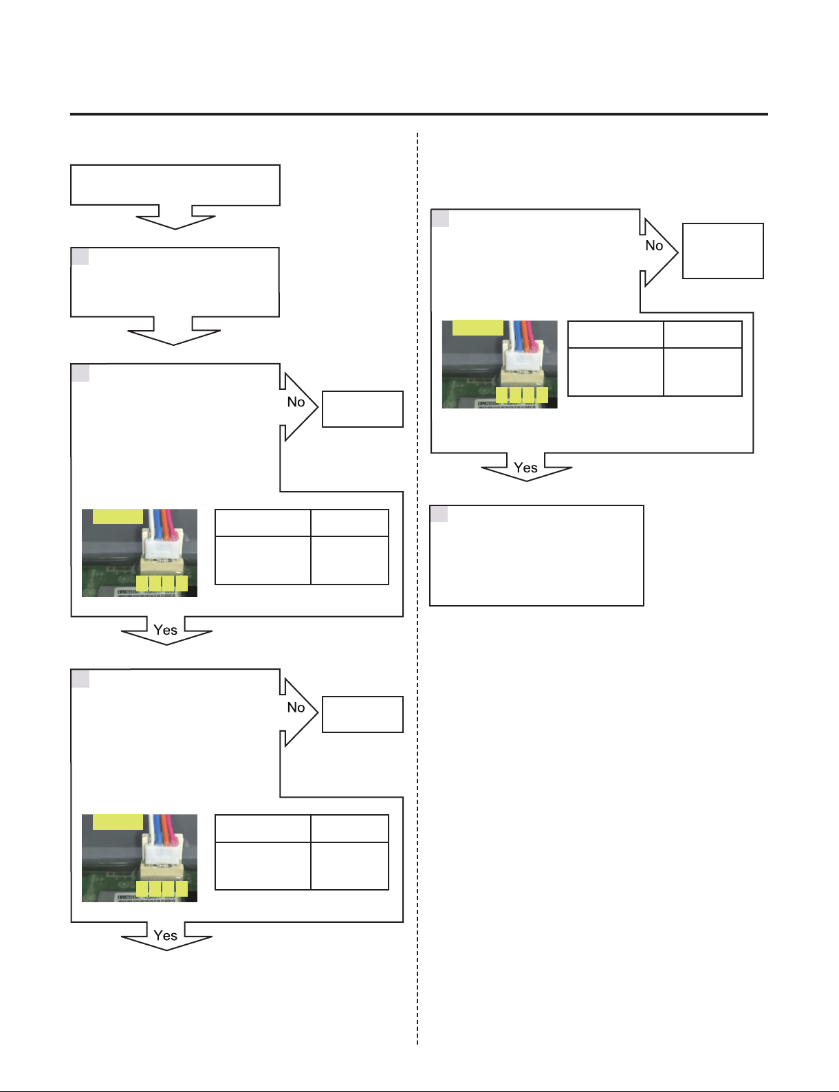
7-6. Refrigerator Fan Error (F1/F2/F3)
Symptom Check Point
1. F1/F2/F3(Option) 1. Check the air ow
2. Check the PCB Fan motor voltage
TEST MODE 2 Voltage [V]
CON7
[F1]3 pin & 5 pin
[F2]4 pin & 6 pin
[F3]20 pin & 22 pin
11.4 ~ 12.6V
TEST MODE 1 Voltage [V]
CON7
[F1]3 pin & 7 pin
[F2]4 pin & 8 pin
[F3]20 pin & 24 pin
Not 0V, 5V
CON7
1
3
5
7
2
4
6
8
9
11
13
15
17
19
21
23
25
26
10
12
14
16
18
20
22
24
W1 FAN
MACHINE ROOM FAN
HYGIENE LED LIGHT
HYGIENE FAN MOTOR
W1 LED PWM LIGHT
W2 FAN
W3 FAN
YL
GY
BO
RD
BL
PK
RD/YL
YL/BL
WH/BN
PR/WH
BK
BN
PR
WH
WH/RD
BL/RD
SB/BK
BO/WH
BO/BL
YL/BK
WH/BK
BL/WH
W2 LED PWM LIGHT
W3 LED PWM LIGHT
Grille Fan
- 32 -
Copyright © 2018-2019 SIGNATURE KITCHEN SUITE.
All rights reserved. Only training and service purposes.
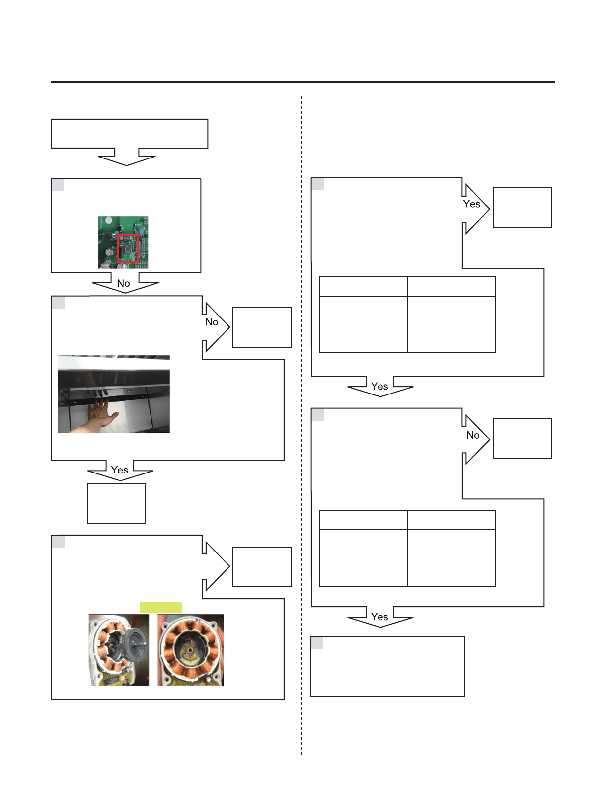
Refrigerator Fan Error (F1/F2/F3)
Check the Fan Motor voltage
Is Fan Motor voltage 8~12V?
Check the Fan Motor voltage
Is Fan Feed Back voltage 0V, 5V?
Reset the unit and Input
Test1 Mode.
(Push the button 1 time)
Go to 3
Change the
Fan motor
Replace
Main PCB
Replace
Main PCB
2
3
4
5
1
Open the Wine door and Check
for air ow
Check the Fan motor.
Rotate fan using hand.
It feel sticky?
Yes
TEST MODE 2 Voltage [V]
CON7
[F1]3 pin & 5 pin
[F2]4 pin & 6 pin
[F3]20 pin & 22 pin
11.4~12.6V
TEST MODE 1 Voltage [V]
CON7
[F1]3 pin & 7 pin
[F2]4 pin & 8 pin
[F3]20 pin & 24 pin
Not 0V, 5V
Explain to customer
6
Go to 4
Fan Motor
- 33 -
Copyright © 2018-2019 SIGNATURE KITCHEN SUITE.
All rights reserved. Only training and service purposes.
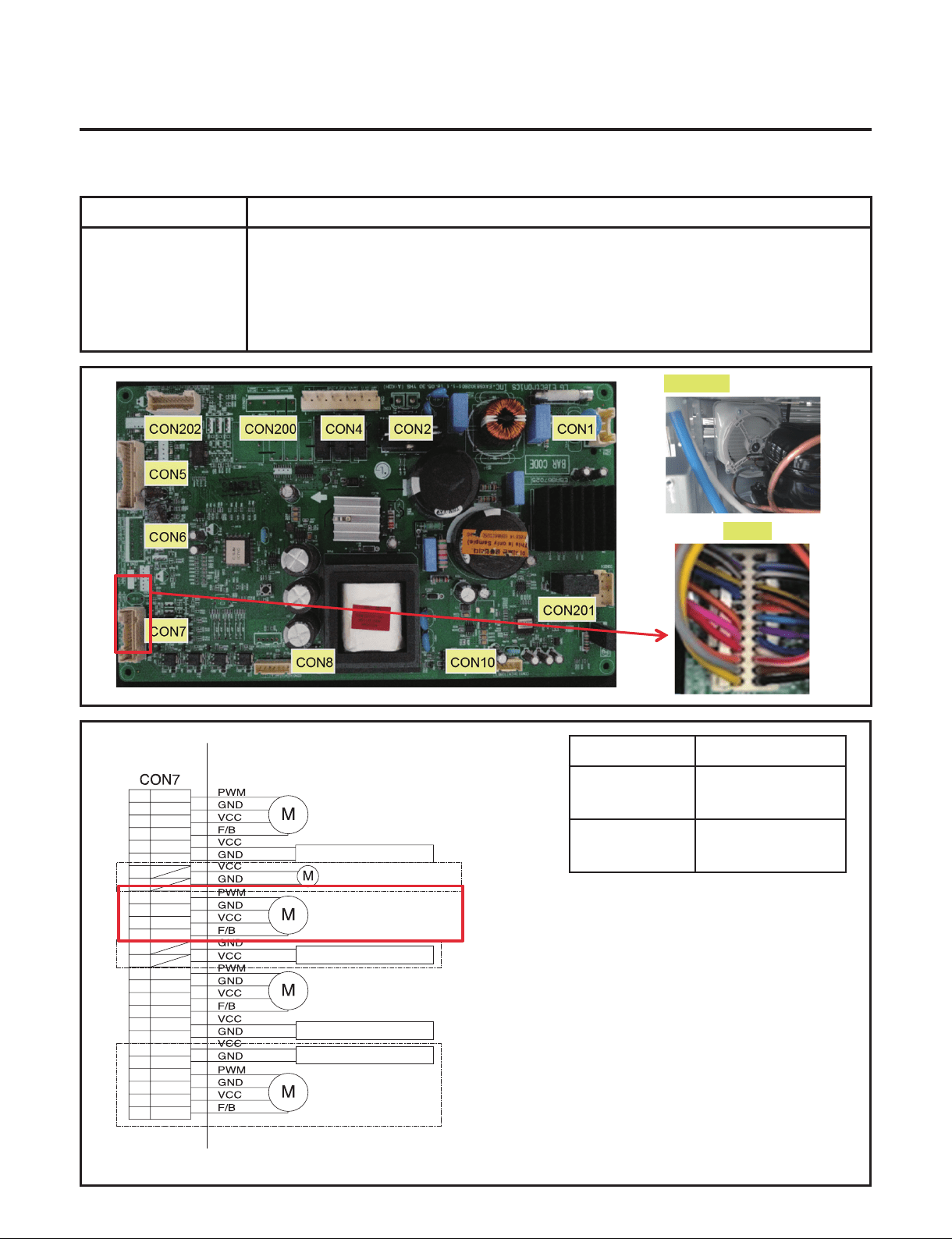
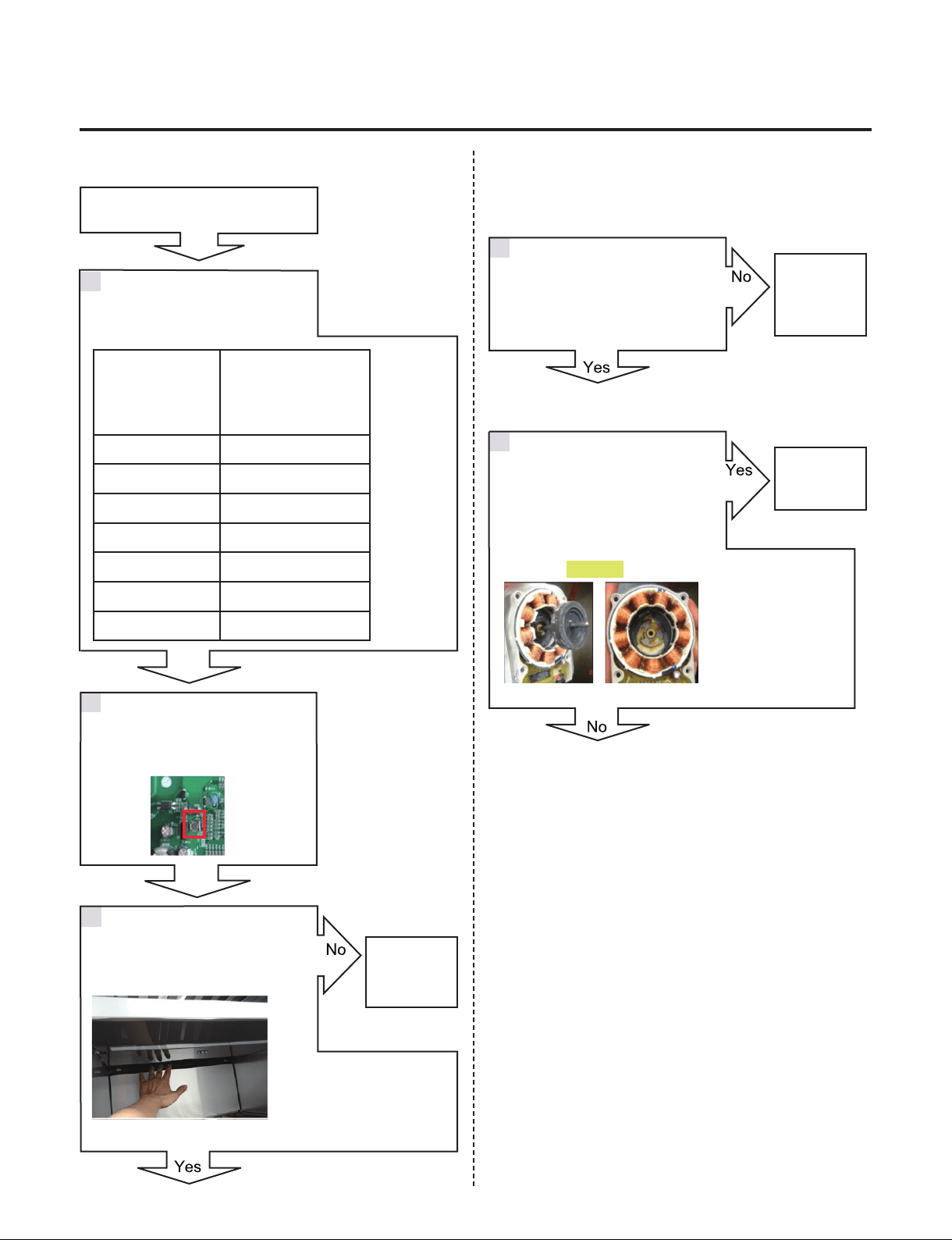
7-7. Condenser Fan Error (CF)
Symptom Check Point
1. CF 1. Check the air ow
2. Check the Connector
3. Check the PCB Fan motor voltage
TEST MODE 1
Voltage [V]
CON7
19 pin & 21 pin
11.4~12.6V
CON7
19 pin & 23 pin
Not 0V, 5V
CON7
1
3
5
7
2
4
6
8
9
11
13
15
17
19
21
23
25
26
10
12
14
16
18
20
22
24
W1 FAN
MACHINE ROOM FAN
HYGIENE LED LIGHT
HYGIENE FAN MOTOR
W1 LED PWM LIGHT
W2 FAN
W3 FAN
YL
GY
BO
RD
BL
PK
RD/YL
YL/BL
WH/BN
PR/WH
BK
BN
PR
WH
WH/RD
BL/RD
SB/BK
BO/WH
BO/BL
YL/BK
WH/BK
BL/WH
W2 LED PWM LIGHT
W3 LED PWM LIGHT
Fan Motor
- 34 -
Copyright © 2018-2019 SIGNATURE KITCHEN SUITE.
All rights reserved. Only training and service purposes.
Fan Motor
Fan Motor
Condenser Fan Error (CF)
Check the Fan Motor voltage
Is Fan Motor voltage 8~12V?
Check the fan rotating.
Does fan rotate?
Check the Fan motor.
Rotate fan using hand.
It feel sticky?
Check the Fan Motor voltage
Is Fan Feed Back voltage 0V, 5V?
Reset the unit and
Input Test1 Mode.
(Push the button 1 time)
Go to 3
Change the
Fan motor
Replace
Main PCB
Change the
motor
2
3
4
5
1
TEST MODE 1
Voltage [V]
CON7
19 pin & 21 pin
11.4~12.6V
TEST MODE 1
Voltage [V]
CON7
19 pin & 23 pin
Not 0V, 5V
Explain to customer
Go to 4
6
- 35 -
Copyright © 2018-2019 SIGNATURE KITCHEN SUITE.
All rights reserved. Only training and service purposes.
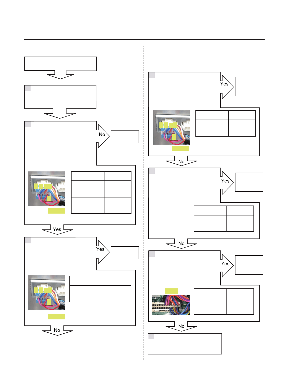
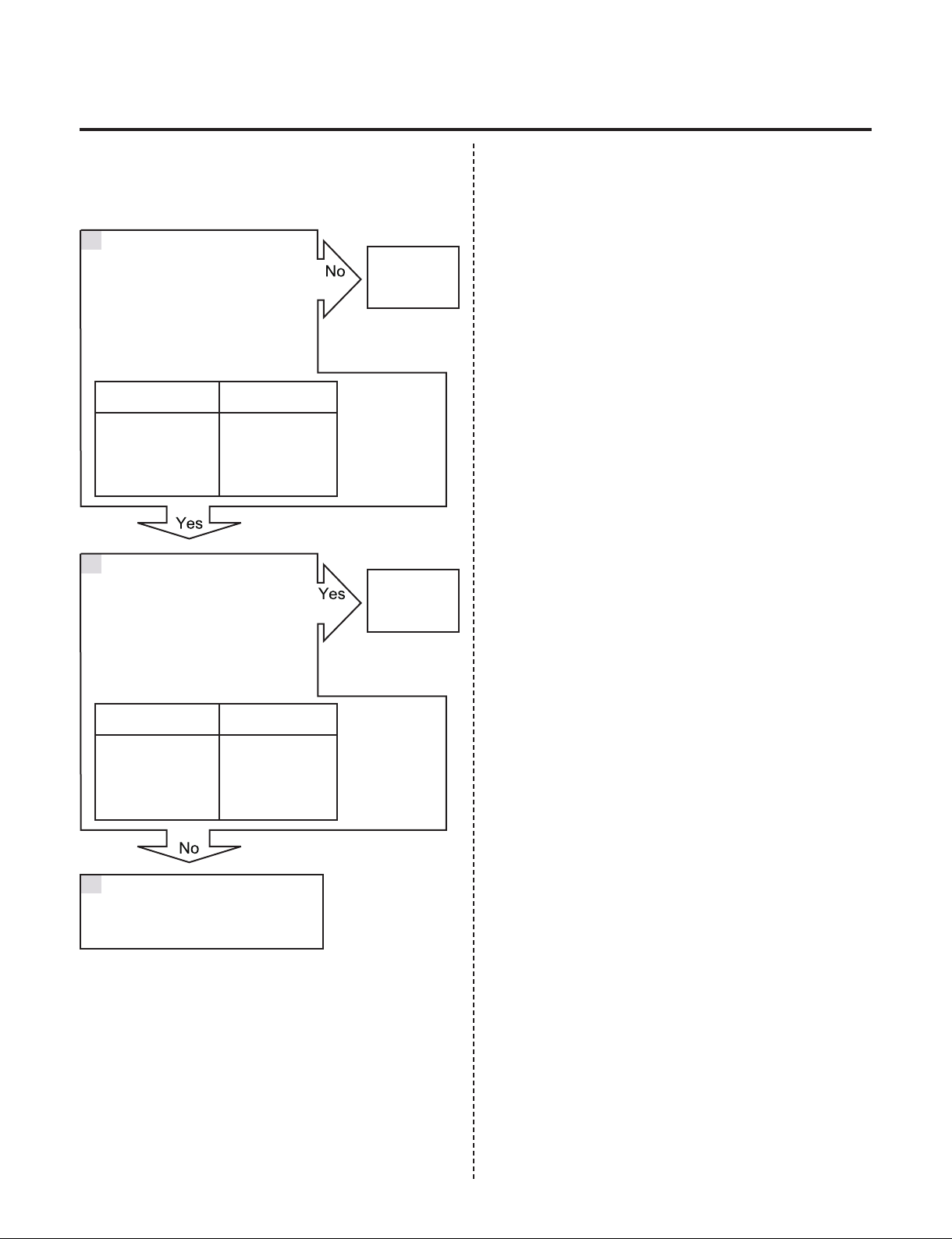
7-8. Communication Error (CO)
Symptom Check Point
1. CO 1. Check the loose connection
2. Check the Hinge connection
Voltage [V]
CON101
1 pin & 2 pin
11.4~12.6V
CON101
2 pin & 5 pin
4.75 ~ 5.25V
CON101
2 Pin & 3 pin
Not 0V, 5V
CON101
2 pin & 4 pin
Not 0V, 5V
CON5
4 pin & 6 pin
Not 0V, 5V
CON5
4 pin & 8 pin
Not 0V, 5V
SMART
BUZZER
H_SENSOR
DOOR 1 SWITCH
DOOR 2 SWITCH
DOOR 3 SWITCH
DAMPER
HEATER
H_SENSOR
BK
SB
PK
BL/WH
BL/WH
1
1
2
3
3
5
7
9
11
13
15
17
19
21
A
5V
GND
A-
B-
5V
GND
SIG
B
23
25
27
29
31
33
4
2
6
8
10
12
14
16
18
20
22
24
26
28
30
32
34
OUTDOOR SENSOR
RD
GY/WH
BL
BO
WH/RD
BN
BN
STEPPING
MOTOR DAMPER
STEPPING
MOTOR DAMPER
A
A-
B-
B
KNOCK ON
SENSOR 1
YL
BK
RD
1
2
3
5V
GND
SIG
KNOCK ON
SENSOR 2
YL
BK
RD
PR
BO/WH
12V
5V
5V
TX
RX
GND
GND
RX
TX
CON101
5432
1
- 36 -
Copyright © 2018-2019 SIGNATURE KITCHEN SUITE.
All rights reserved. Only training and service purposes.
5
4
3
2
1
CON101
CON5
CON101
CON101
Communication Error (CO)
Check the voltage.
Is CON101 2 pin & 4 pin
voltage 0V or 5V?
Check the voltage.
Is CON101 1 pin & 2 pin
voltage 12V?
Is CON101 2 pin & 5 pin
Voltage 5V?
Check the voltage.
Is CON101 2 pin & 3 pin
voltage 0V or 5V?
Check the loose connection
Check the voltage.
Is CON5 4 pin & 6 pin
voltage 0V or 5V?
Check the voltage.
Is CON5 4 pin & 8 pin
voltage 0V or 5V?
Change the
Main PCB
Change the
Display
Change the
Main PCB
Change the
Display
Change the
Main PCB
2
3
4
5
6
1
Voltage [V]
CON5
2 pin & 4 pin
11.4~12.6V
CON5
4 pin & 10 pin
4.75 ~ 5.25V
Voltage [V]
CON101
2 pin & 3 pin
Not
0V, 5V
Voltage [V]
CON5
4 pin & 6 pin
Not
0V, 5V
Voltage [V]
CON5
4 pin & 8 pin
Not
0V, 5V
Voltage [V]
CON101
2 pin & 4 pin
Not
0V, 5V
Explain to customer
7
5
4
3
2
1
5
4
3
2
1
- 37 -
Copyright © 2018-2019 SIGNATURE KITCHEN SUITE.
All rights reserved. Only training and service purposes.
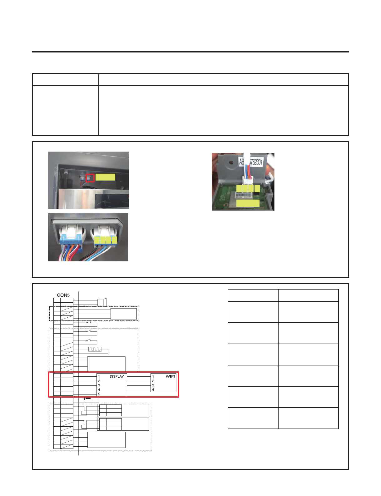
7-9. Communication Error (Od)
Symptom Check Point
1. Od 1. Check the loose connection
Voltage [V]
CON102
1 pin & 4 pin
4.75 ~ 5.25V
CON102
2 pin & 4 pin
Not 0V, 5V
CON102
3 Pin & 4 pin
Not 0V, 5V
CON103
1 pin & 4 pin
4.75 ~ 5.25V
CON103
2 pin & 4 pin
Not 0V, 5V
CON103
3 pin & 4 pin
Not 0V, 5V
21
CON102
CON103
4
4
3
3
2 1
SMART
BUZZER
H_SENSOR
DOOR 1 SWITCH
DOOR 2 SWITCH
DOOR 3 SWITCH
DAMPER
HEATER
H_SENSOR
BK
SB
PK
BL/WH
BL/WH
1
1
2
3
3
5
7
9
11
13
15
17
19
21
A
5V
GND
A-
B-
5V
GND
SIG
B
23
25
27
29
31
33
4
2
6
8
10
12
14
16
18
20
22
24
26
28
30
32
34
OUTDOOR SENSOR
RD
GY/WH
BL
BO
WH/RD
BN
BN
STEPPING
MOTOR DAMPER
STEPPING
MOTOR DAMPER
A
A-
B-
B
KNOCK ON
SENSOR 1
YL
BK
RD
1
2
3
5V
GND
SIG
KNOCK ON
SENSOR 2
YL
BK
RD
PR
BO/WH
12V
5V
5V
TX
RX
GND
GND
RX
TX
1 2 3 4
- 38 -
Copyright © 2018-2019 SIGNATURE KITCHEN SUITE.
All rights reserved. Only training and service purposes.
21
CON103
43
21
CON103
43
21
CON103
43
Communication Error (Od)
Check the voltage.
Is CON103 3 pin & 4 pin
voltage 0V or 5V?
Check the loose connection
Change the
Display
Change the
Display
Change the
WiFi PCB
2
3
4
1
Voltage [V]
CON103
1 pin & 4 pin
4.75 ~ 5.25V
Voltage [V]
CON103
2
nd
pin & 4
th
pin
Not
0V, 5V
Voltage [V]
CON103
3 pin & 4 pin
Not
0V, 5V
Check the loose connection
Change the Display, WiFi PCB
Explain to customer
5
Check the voltage.
Is CON103 1 pin & 4 pin
Voltage 5V?
Check the voltage.
Is CON103 2 pin & 4 pin
voltage 0V or 5V?
- 39 -
Copyright © 2018-2019 SIGNATURE KITCHEN SUITE.
All rights reserved. Only training and service purposes.
7-10. Poor cooling in Wine compartment
Symptom Check Point
1. Poor cooling in Wine
compartment
1. Check the sensor resistance
2. Check the air ow
3. Check the air Temperature
4.Check the Fan motor sticky
4. Check the Fan motor voltage
Duct
Status
Air Flow
Windy
Air Temperature
Cold
TEST MODE 1
Voltage [V]
CON7
3 pin & 5 pin, 4 pin & 6 pin20 pin
& 22 pin
11.4~12.6V
CON7
3 pin & 7 pin, 4 pin & 8 pin20 pin
& 24 pin
Not 0V, 5V
CON202
5 pin & 7 pin , 13 pin & 15 pin,
21 pin & 23 pin
Resistance [Ω]
-22ºF / -30ºC 130k
-13ºF / -25ºC 102k
-4ºF / -20ºC 77k
-13ºF / -25ºC 60k
14ºF / -10ºC 47k
23ºF / -5ºC 37.5k
32ºF / 0ºC 30k
CON7
1
3
5
7
2
4
6
8
9
11
13
15
17
19
21
23
25
26
10
12
14
16
18
20
22
24
W1 FAN
MACHINE ROOM FAN
HYGIENE LED LIGHT
HYGIENE FAN MOTOR
W1 LED PWM LIGHT
W2 FAN
W3 FAN
YL
GY
BO
RD
BL
PK
RD/YL
YL/BL
WH/BN
PR/WH
BK
BN
PR
WH
WH/RD
BL/RD
SB/BK
BO/WH
BO/BL
YL/BK
WH/BK
BL/WH
W2 LED PWM LIGHT
W3 LED PWM LIGHT
CON202
CON7
WH
WH
BK
BK
RD
RD
BO
BO
BL
BL
SB
GY/RD
WH/BK
YL
PK
BO/BL
BO/BL
1
3
5
7
9
11
13
15
17
19
21
23
2
4
6
8
10
12
14
16
18
20
22
24
VCC
GND
VCC
GND
VCC
GND
COM
A
B
B-
A-
1
2
5
6
3.4
3WAY/4WAY
VALVE
W1 SENSOR
W1 DEFROSTING SENSOR
W2 SENSOR
W2 DEFROSTING SENSOR
W3 SENSOR
W3 DEFROSTING SENSOR
W1 LED LIGHT
W2 LED LIGHT
W3 LED LIGHT
- 40 -
Copyright © 2018-2019 SIGNATURE KITCHEN SUITE.
All rights reserved. Only training and service purposes.
Fan Motor
Poor cooling in Refrigerator
compartment
Check the air temperature.
Is it cold?
Check the Fan motor.
Rotate fan using hand.
It feel sticky?
Open the fresh food door and
Check for air ow
Check the sensor resistance.
CON7
5 pin & 7 pin
13 pin & 15 pin
21 pin & 23 pin
Resistance [Ω]
-22ºF / -30ºC 130k
-13ºF / -25ºC 102k
-4ºF / -20ºC 77k
-13ºF / -25ºC 60k
14ºF / -10ºC 47k
23ºF / -5ºC 37.5k
32ºF / 0ºC 30k
Check the F
Fan Motor
Go to 5
Check the
Compressor
and sealed
system
Change the
Fan motor
3
4
5
1
Reset the unit and
Input Test1 Mode.
(Push the button 1 time)
2
- 41 -
Copyright © 2018-2019 SIGNATURE KITCHEN SUITE.
All rights reserved. Only training and service purposes.
Check the Fan Motor voltage
Is Fan Motor voltage 8~12V?
Check the Fan Motor voltage
Is Fan Feed Back voltage 1~5V?
Replace
Main PCB
Change the
motor
6
7
TEST MODE 1
Voltage [V]
CON7
3 pin & 5 pin
4 pin & 6 pin
20 pin & 22 pin
11.4~12.6V
TEST MODE 1 Voltage [V]
CON7
3 pin & 7 pin
4 pin & 8 pin
20 pin & 24 pin
Not 0V, 5V
Explain to customer
8
- 42 -
Copyright © 2018-2019 SIGNATURE KITCHEN SUITE.
All rights reserved. Only training and service purposes.
7-11. Room lamp doesn’t work
Symptom Check Point
1. Freezer room lamp
doesn’t work
1. Check the freezer door switch sticky
2. Check the door S/W resistance
3. Check the LED Lamp
Resistance [Ω]
Door S/W
No magent near
the switch
Innity
Magnet is near the
switch
0
*PWM Control Voltage range
CON7
Voltage [V]
9 pin & 11 pin
5.7~12.6V
10 pin & 12 pin
5.7~12.6V
14 pin & 16 pin
5.7~12.6V
*PWM Control Voltage range
LED Lamp
Voltage [V]
White &Yellow
Closed 0~2V
Open 5.7~12.6V
Door S/W
CON7
LED Lamp
1
3
5
7
2
4
6
8
9
11
13
15
17
19
21
23
25
26
10
12
14
16
18
20
22
24
W1 FAN
MACHINE ROOM FAN
HYGIENE LED LIGHT
HYGIENE FAN MOTOR
W1 LED PWM LIGHT
W2 FAN
W3 FAN
YL
GY
BO
RD
BL
PK
RD/YL
YL/BL
WH/BN
PR/WH
BK
BN
PR
WH
WH/RD
BL/RD
SB/BK
BO/WH
BO/BL
YL/BK
WH/BK
BL/WH
W2 LED PWM LIGHT
W3 LED PWM LIGHT
- 43 -
Copyright © 2018-2019 SIGNATURE KITCHEN SUITE.
All rights reserved. Only training and service purposes.
room lamp doesn’t work
The Switch senses if the door is
open or close.
When the door open, lamp On
When the door Close, lamp Off
Check the PCB Voltage.
Is voltage 5.7 ~ 12.6V?
(While door open)
Change the
PCB
Change the
Door S/W
Change the
LED Lamp
Change the
LED Lamp
Explain to
customer
Change the
Door S/W
3
2
6
41
5
Explain to customer
7
Resistance [Ω]
Door S/W
No magent
near the switch
Innity
Magnet is near
the switch
0
Voltage [V]
CON7
All LED PART
5.7~12.6V
Check the door S/W resistance.
Is it correct compared with table?
CON7
*PWM Control Voltage range
Check the LED Lamp voltage
Is voltage 5.7~12.6V?
LED Lamp
Check the LED Lamp voltage.
Is it 0~2V? (While door closed)
Check the LED Lamp voltage.
Is it 5.7~12.6V? (While door open)
LED Lamp
- 44 -
Copyright © 2018-2019 SIGNATURE KITCHEN SUITE.
All rights reserved. Only training and service purposes.
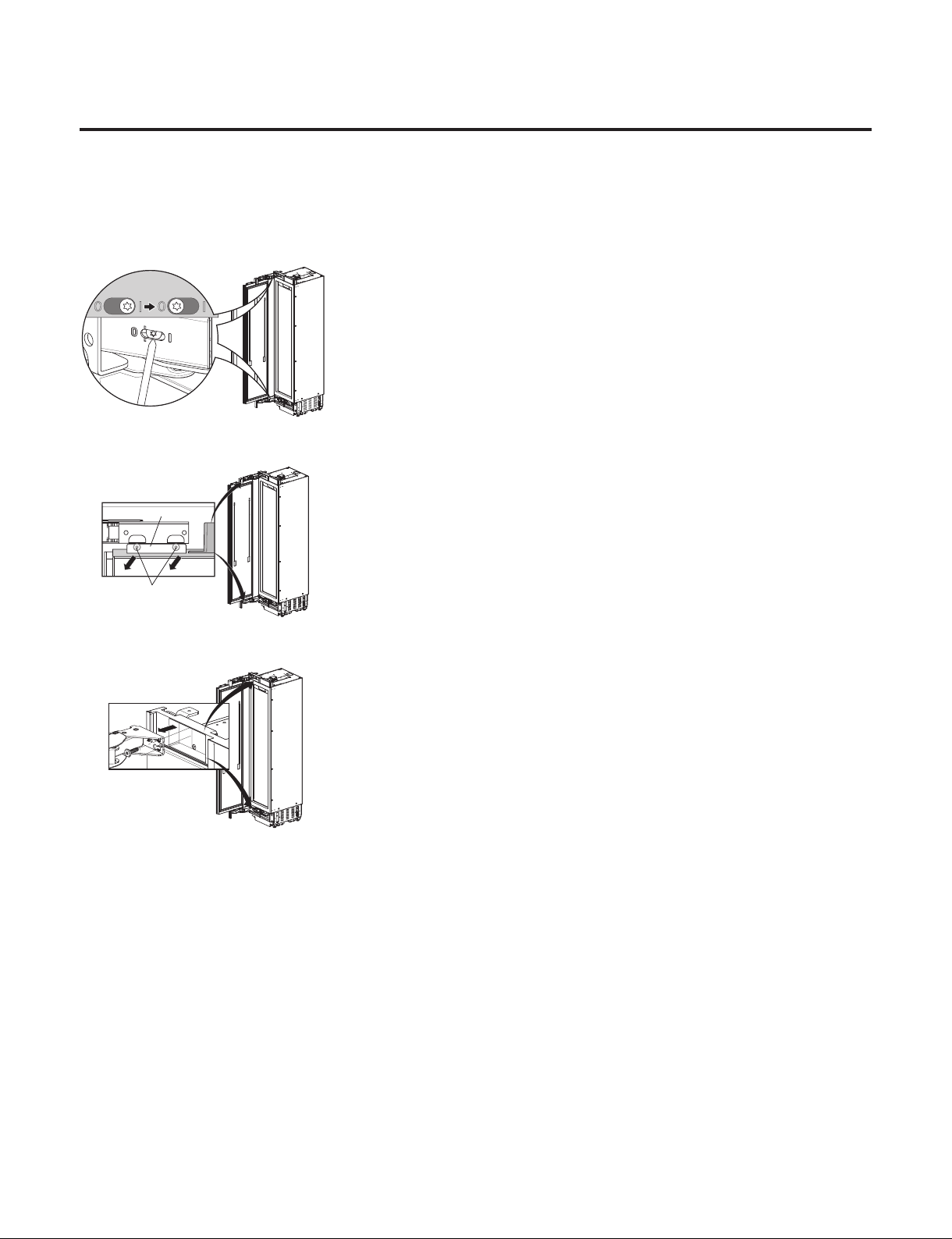
8. HOW TO DISASSEMBLE AND ASSEMBLE
1. How to Disassemble Door
1) Release the spring on the hinge. Loosen the screw from l to 0
18,24 Wine - Right
1.
2.
2) Unscrew (1.) and remove (2.) the door.
1.
2.
3) Remove the hinges.
1.
2.
4) Assembly is reverse order.
- 45 -
Copyright © 2018-2019 SIGNATURE KITCHEN SUITE.
All rights reserved. Only training and service purposes.
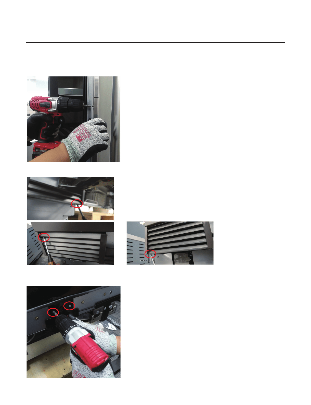
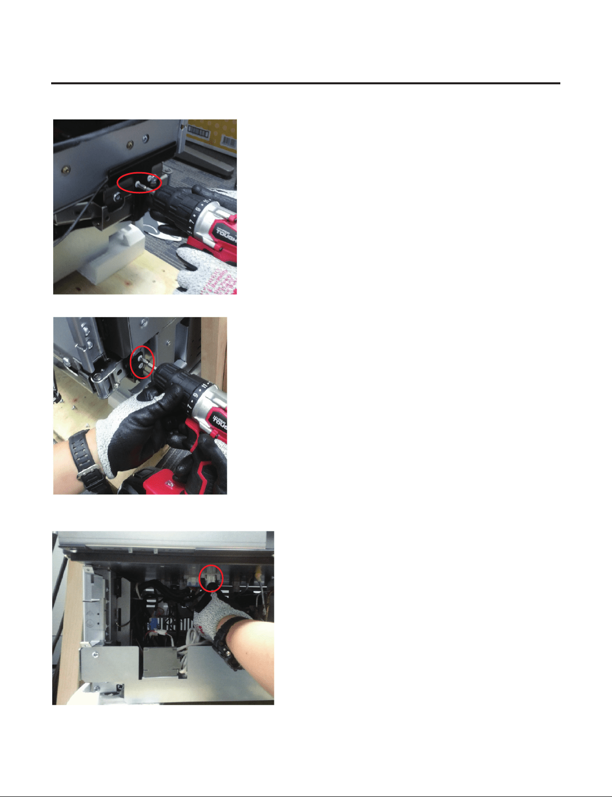
2. How to Disassemble Knock-on Sensor
1) Remove the screws and door panel
2) Remove 3 screws to pull out the Cover machinary room (Wine-Right Hinge)
3) Remove the 2 screws to pull out the Cover,PCB
- 46 -
Copyright © 2018-2019 SIGNATURE KITCHEN SUITE.
All rights reserved. Only training and service purposes.
4) Remove the 2 screws to detach the Link
5) Remove the 2 screws to detach the Holder Bracket
6) Detach the harness from the main PCB
7) Assembly is reverse order.
- 47 -
Copyright © 2018-2019 SIGNATURE KITCHEN SUITE.
All rights reserved. Only training and service purposes.
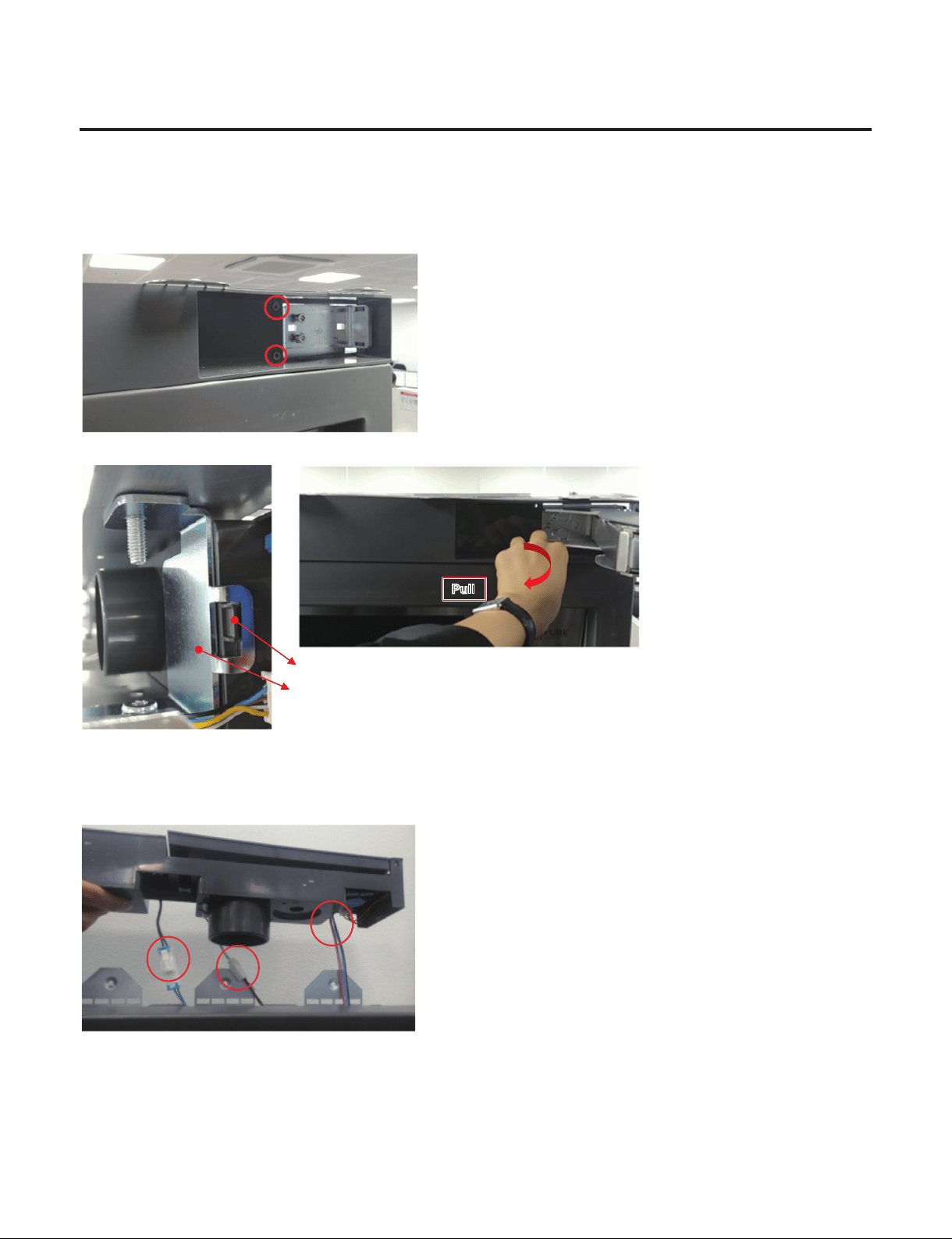
3. How to Disassemble Top, Cover
1) Disassemble the Door.
2) Remove 2 screws located at Top cover.
3) Pull out the Top cover and separate 3 housings.
Bracket
Rib
PullPull
Left side is xed by this rib.
So the cover need to be pull to disassemble the rib from bracket.
4) Assembly is reverse order.
- 48 -
Copyright © 2018-2019 SIGNATURE KITCHEN SUITE.
All rights reserved. Only training and service purposes.
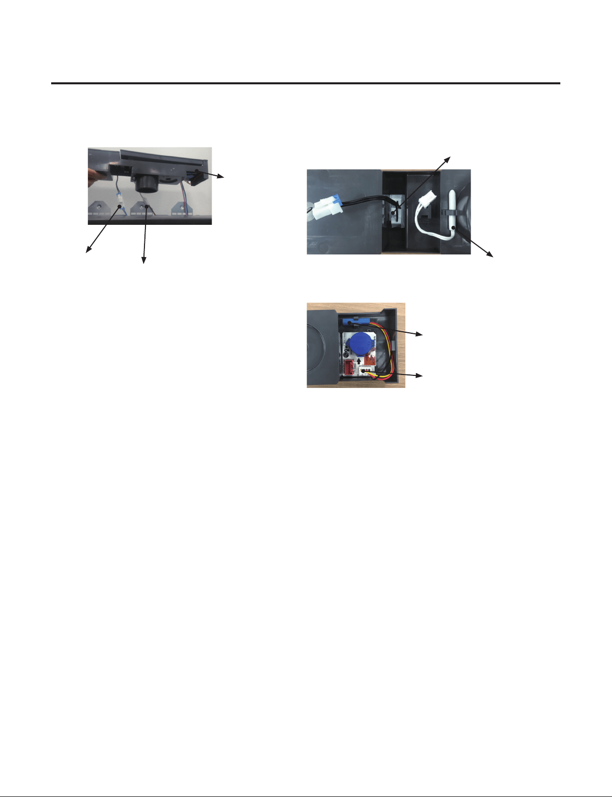
4. How to replace the Door Switch/SDS PCB/Temperature sensor?
1) First, Reassemble the Top,Cover . (With reference Top,cover SVC)
2) Pull out the Top cover and separate 3 housings.
①
Door switch
②
Temperature
sensor
③
SDS PCB
①
Door switch
②
Temperature
sensor
No Humidity Sensor in
Wine Model
③
SDS PCB
3) Pull out the Top,Cover and replace the defect part.
(If the Door switch needs to be replaced, you can replace the
①
.
- 49 -
Copyright © 2018-2019 SIGNATURE KITCHEN SUITE.
All rights reserved. Only training and service purposes.
5. How to remove the Cover Machinery Room
1) Open the door
2) Remove the 1 Screw located at under the Hinge
3) Remove 2 Screws located at opposite the hinge.
4) Pull out the cover machinery room.
- 50 -
Copyright © 2018-2019 SIGNATURE KITCHEN SUITE.
All rights reserved. Only training and service purposes.
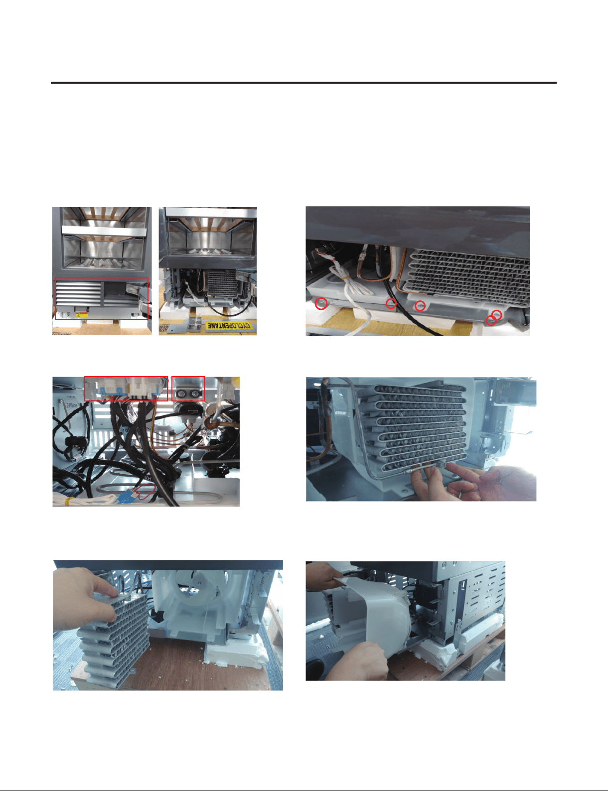
6. How to Sliding out Machinery room ( 1 / 4 )
Preparation for Sealed System Repair SVC(Compressor, Condenser)
※
GR-1137GPNM, GR-3137GPNM Machine rooms are Same structure and SVC order is
same. Refer to exploded View page (3/4).
1) Open the door and remove the Cover. 2) Loosen the marked Screws. (5 Points)
Recommend to use short tip
3) Remove 1) 3Way valve, 2)PCB Connector housing. 4) Lift slightly up on condenser to separate
5) Rotate Condenser to the side and move it. If SVC the
Condenser, Work in current state.
6) Remove the Guide fan housing and take it out from the
Refrigerator.
If SVC the Guide Fan, Work in current state. And Refer to the
Page (4/4)
Caution :
When handling the PIpe, be careful with the Pipe Crack.
1)2)
- 51 -
Copyright © 2018-2019 SIGNATURE KITCHEN SUITE.
All rights reserved. Only training and service purposes.
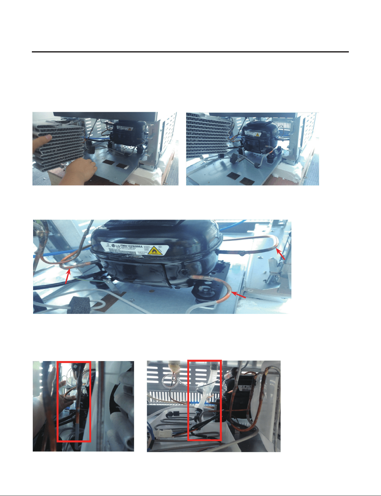
6. How to Sliding out Machinery room ( 2 / 4 )
Preparation for Sealed System Repair SVC(Compressor, Condenser)
7) Slide out the machine room SVC Slide by putting the condenser sideways.
When sliding out the machine room, be careful not to damage the Suction Joint(Back of the Compressor).
8) Pay attention to each position of the Compressor and perform sealed system repair
Refer to Sealed System Repair Page.
9) Assembly is reverse order
Do not miss the Tube Assembly drain to be in position again.
If not, it cause a risk of leaks in customer’s furniture and oor.
※
GR-1137GPNM, GR-3137GPNM Machine rooms are Same structure.
Refer to next page exploded View.
Processing(Charging)
Suction
Discharge
- 52 -
Copyright © 2018-2019 SIGNATURE KITCHEN SUITE.
All rights reserved. Only training and service purposes.
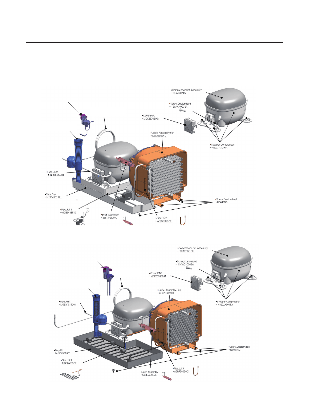
6. How to Sliding out Machinery room ( 3 / 4 )
Please refer to the below exploded view of the Cycle Parts.
GR-1137GPNM (18W)
GR-3137GPNM (24W)
▪ Valve Assembly,Pipe
-AJU74012401
▪ Valve Assembly,Pipe
-AJU75332501
▪ Tube Assembly, Drain
- 5251JA3004E
▪ Pipe,Joint
-MGE64934801
▪ Tube Assembly, Drain
-5251JA3004E
▪ Pipe, Joint
-MGE64934802
- 53 -
Copyright © 2018-2019 SIGNATURE KITCHEN SUITE.
All rights reserved. Only training and service purposes.
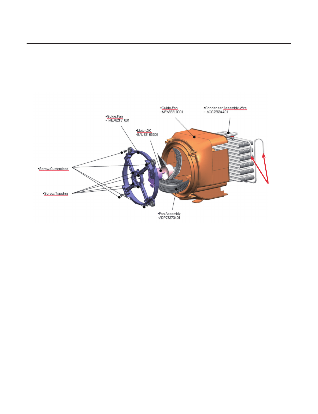
6. How to Sliding out Machinery room ( 4 / 4 )
Guide Fan Assembly SVC With Condenser.
- SVC part : Guide Fan , Fan Assembly, Motor DC, Condenser
Refer to Exploded view in Guide Fan Assembly.
1) Condenser
- Disassemble the Condenser. There is no Screw in Condenser.
- Move to Condenser beside to disassemble. Refer to Sliding out Machinery Room page.
2) Motor DC, Fan Assembly
- Disassemble the Guide fan Assembly from the Refrigerator.
- Loosen the Screw Customized 4 points.
- If Need to SVC Fan Assembly, Just pull out the Fan and Change the part.
- If Need to SVC Motor DC, Loosen the Screw Tapping from Guide Fan and Change.
3) Disassemble the Guide fan Assembly from the Refrigerator.
- Reassemble in reverse order of disassembly.
- Do not miss the Damper Rubber Located on Screw Customized.
Brazing point
- 54 -
Copyright © 2018-2019 SIGNATURE KITCHEN SUITE.
All rights reserved. Only training and service purposes.
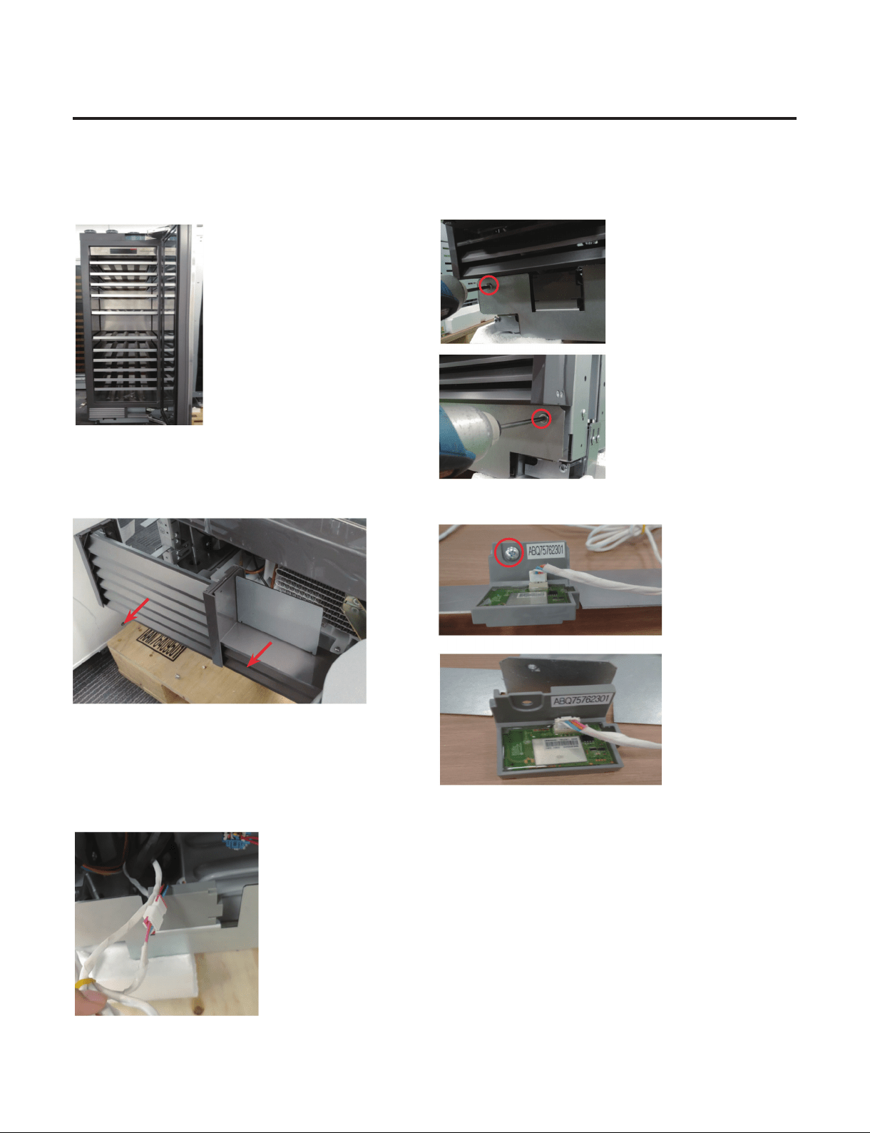
7. How to SVC the Wi-Fi module?
1) Open the door 2) Remove the Screws located at Cover front.
3) Remove the Cover machinery room. 4) Remove the WiFi module from the Cover front.
- Remove the 1 Screw
5) Separate the WiFi module housing from
the Main PCB housing.
6) Assembly is reverse order.
- 55 -
Copyright © 2018-2019 SIGNATURE KITCHEN SUITE.
All rights reserved. Only training and service purposes.
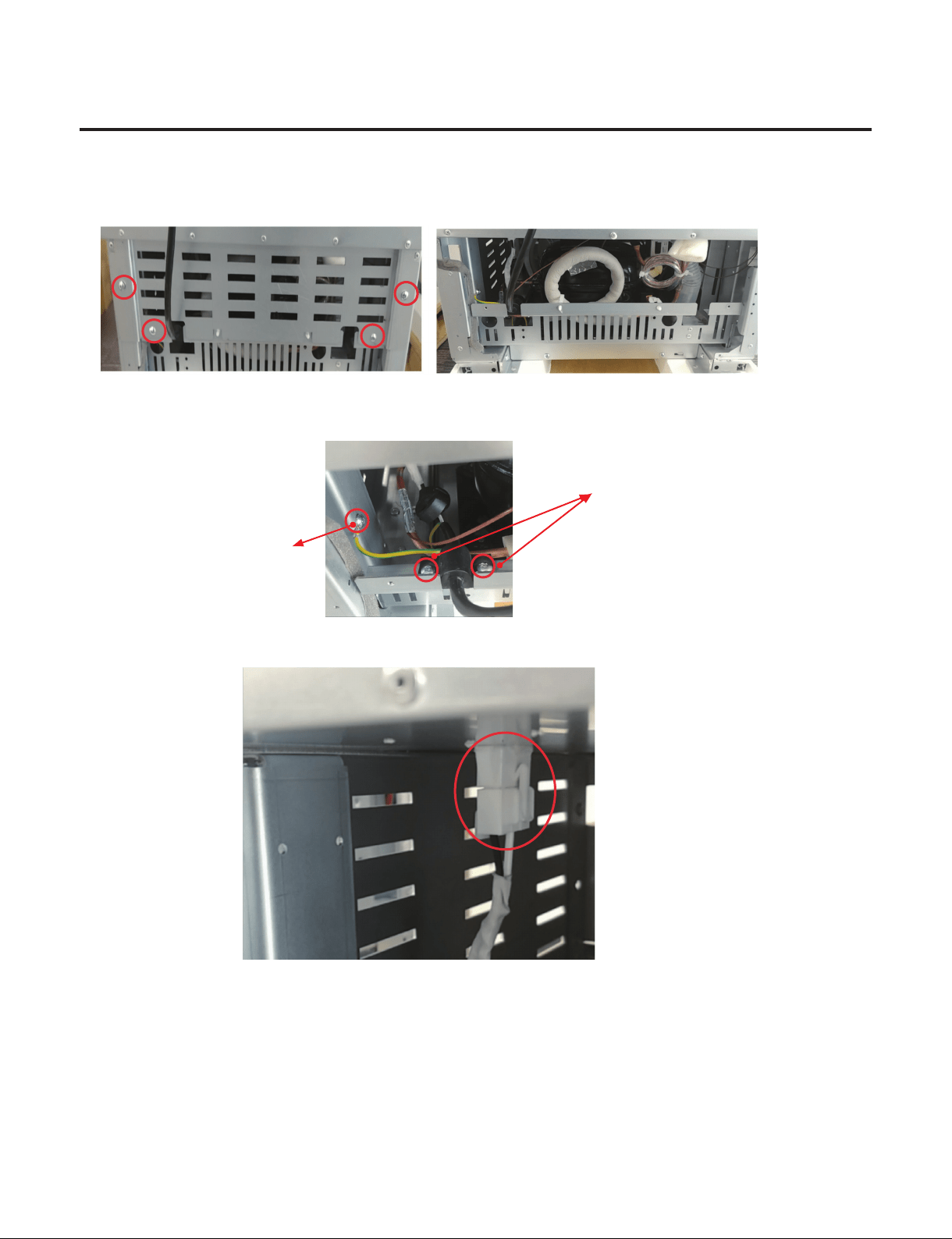
8. How to SVC the Power Cord?
1) Remove screws on Cover machinery Back.
2) Remove the earth screw and power cord screw.
earth screw
Power cord screw
3) Separate the Power Cord housing on the top.
4) Assembly is reverse order.
- 56 -
Copyright © 2018-2019 SIGNATURE KITCHEN SUITE.
All rights reserved. Only training and service purposes.
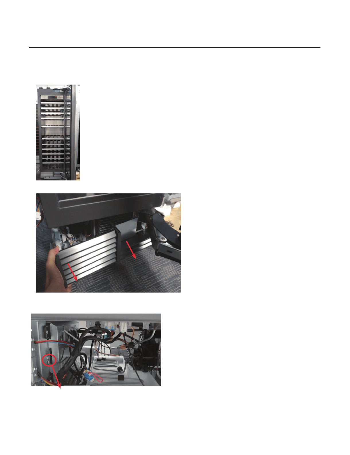
9. How to SVC the Main PCB? (1/2)
1) Open the door
2) Remove the Cover machinery and Cover front.
3) Remove the earth screw that is located at the left side.
Main PCB earth screw

- 57 -
Copyright © 2018-2019 SIGNATURE KITCHEN SUITE.
All rights reserved. Only training and service purposes.
9. How to SVC the Main PCB? (2/2)
4) Separate the Main PCB housing from the Supporter Housing that is located at bottom of Case. (Total 9 housings)
5) Remove the 2 screws.
6) Move Main PCB to the right and pull out the Main PCB.
④
①
②
⑤
③
⑥
⑦ ⑧
⑨
- 58 -
Copyright © 2018-2019 SIGNATURE KITCHEN SUITE.
All rights reserved. Only training and service purposes.
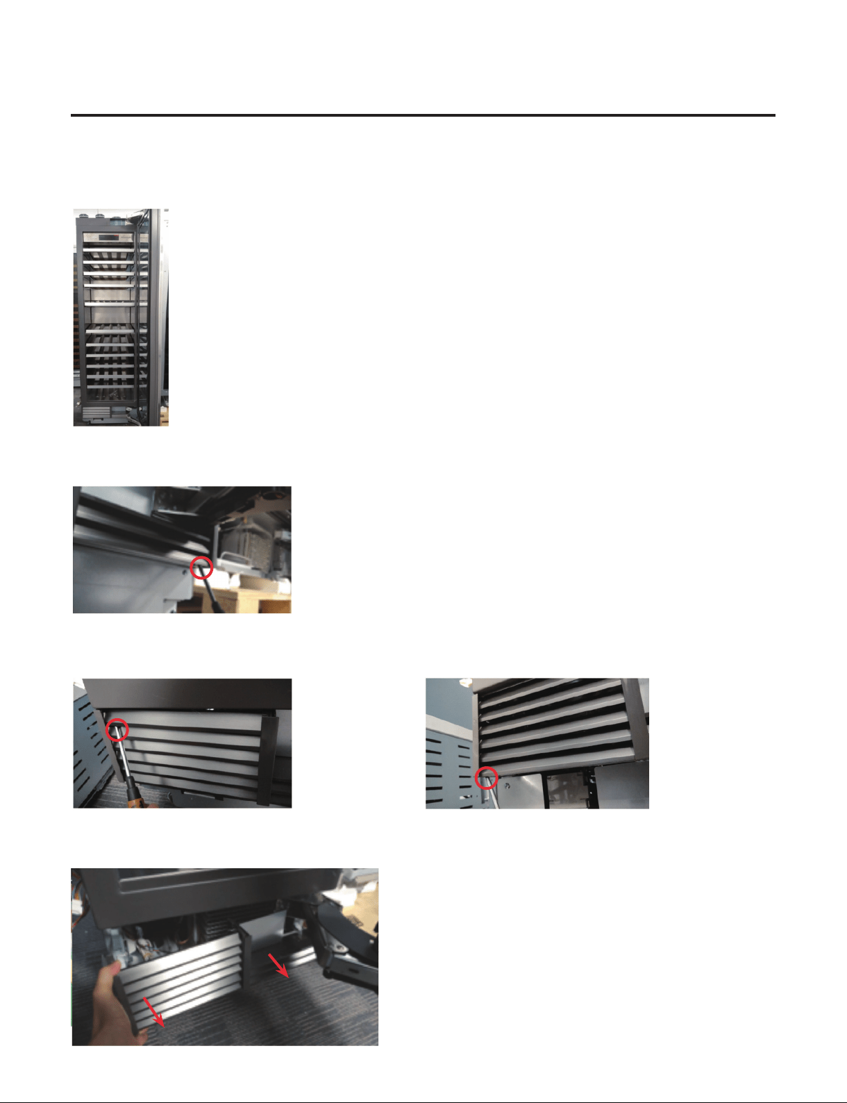
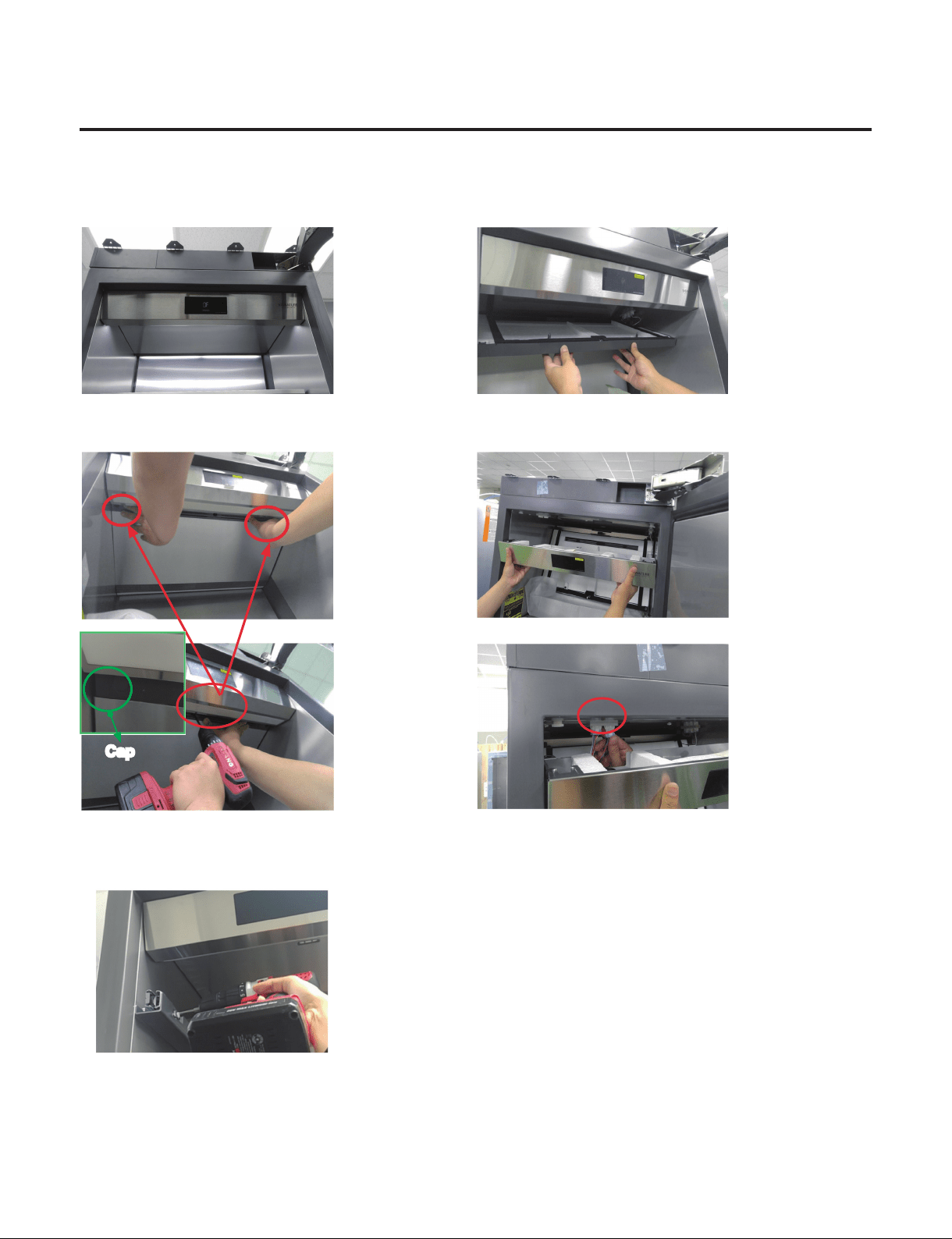
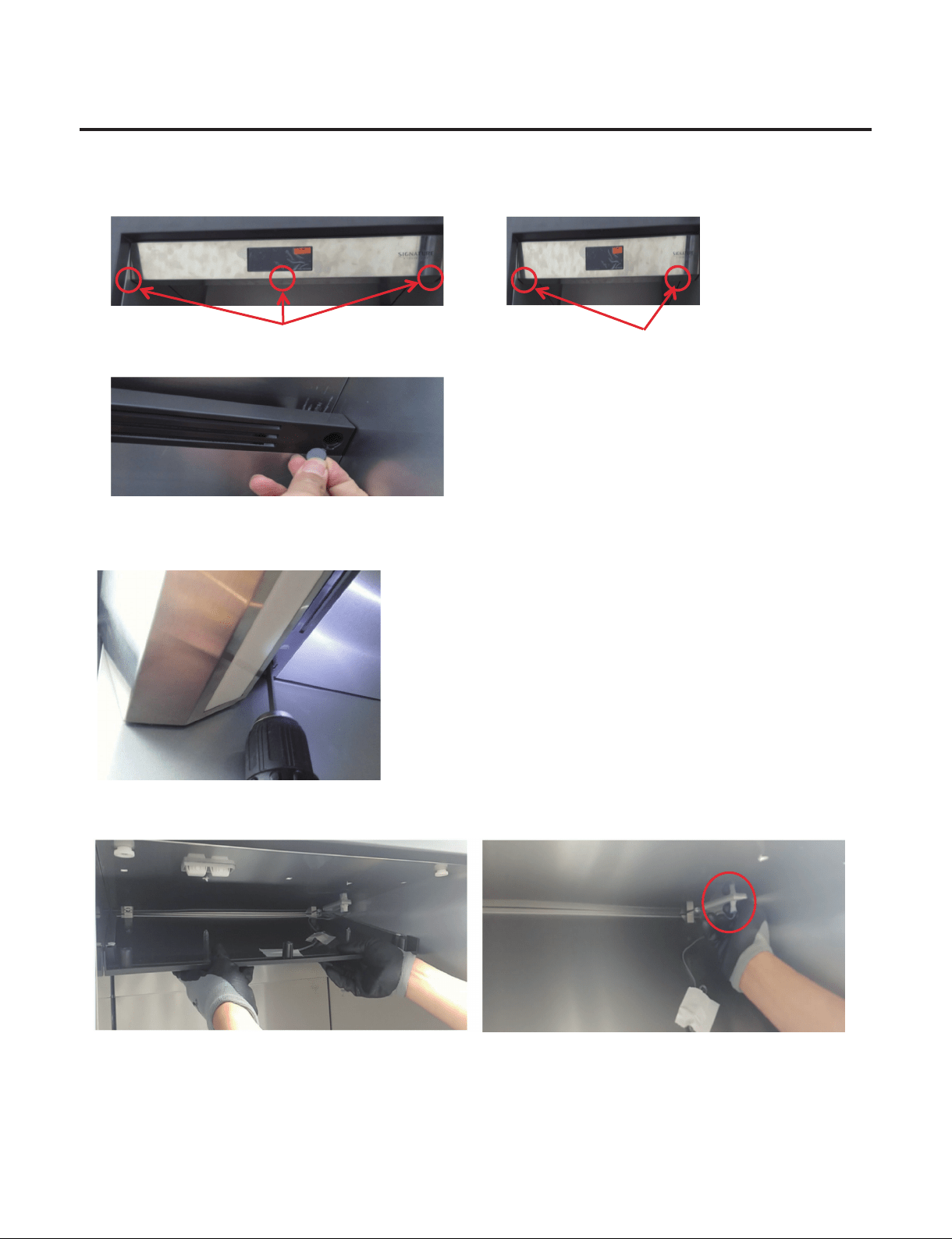
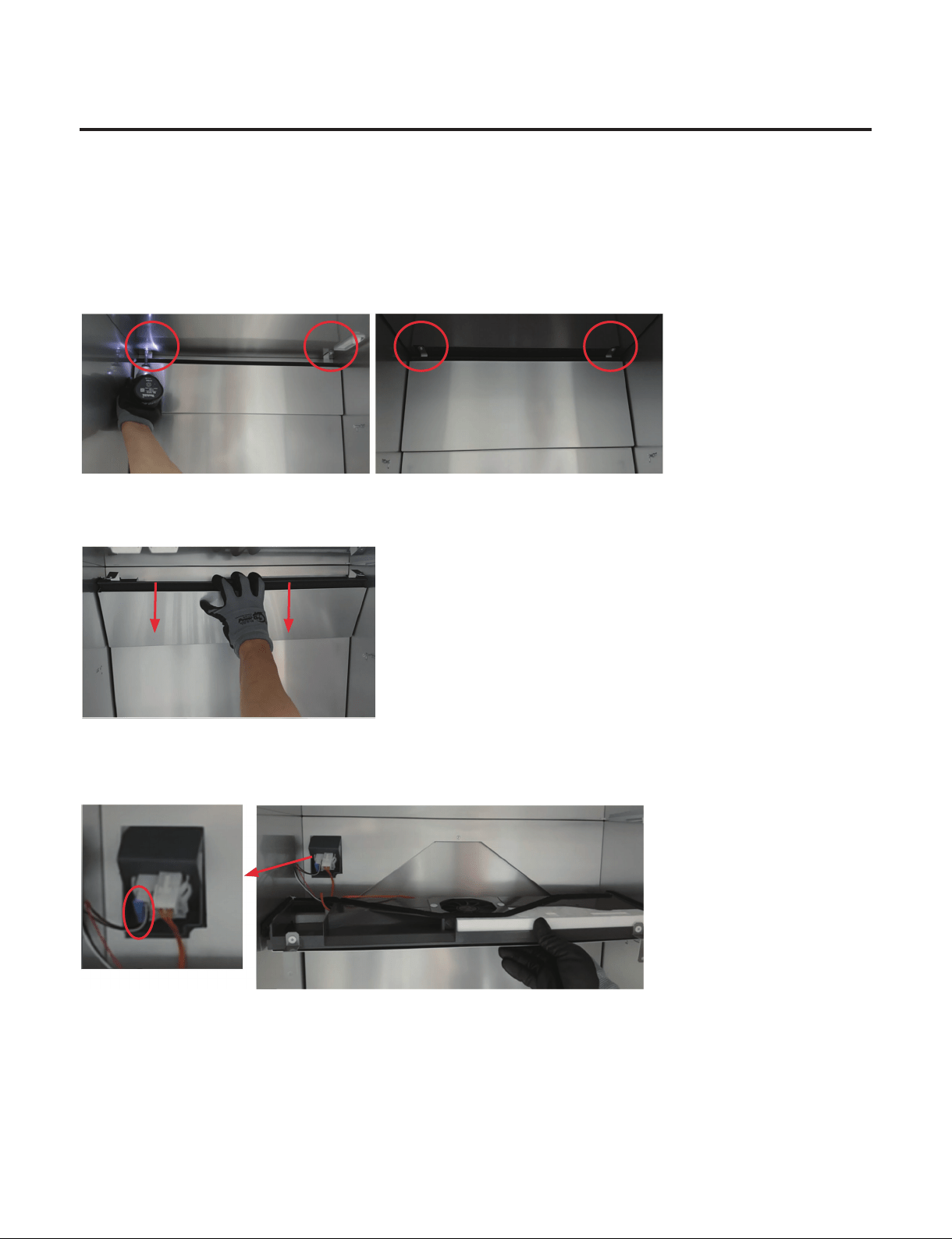
10. How to Disassemble Control Panel
1) Open the Door 3) Pull out the Top Duct
2) Remove 2 caps (24inch-3caps) and screws located
at Top Duct.
4) Pull out the Control Panel and separate 2 housings.
5) Assembly is reverse order.
※
If you have a problem to remove top duct screws by Guide Rail.
You need to remove the both rail on the top.
Cap
- 59 -
Copyright © 2018-2019 SIGNATURE KITCHEN SUITE.
All rights reserved. Only training and service purposes.
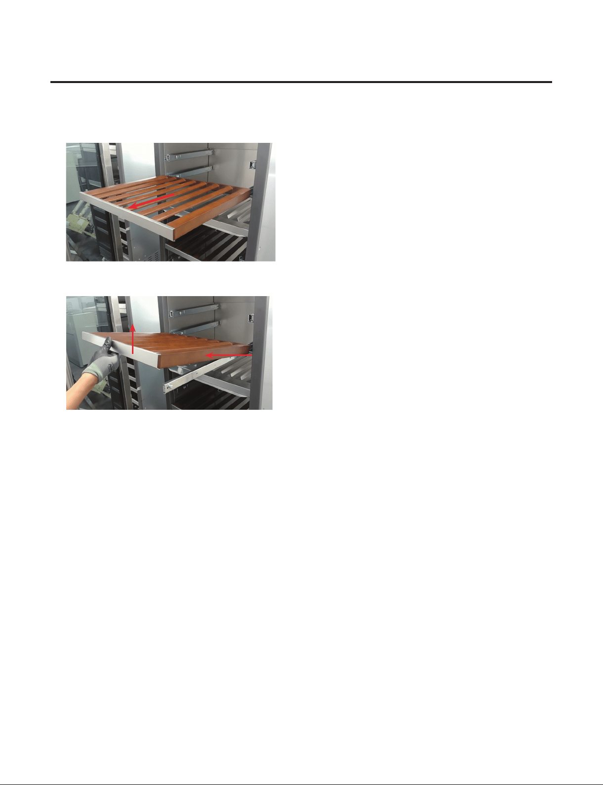
11. How to Disassemble Shelf
1) Pull the Shelf to the end
2) Raise up and pull the Shelf by this direction
3) Assembly is reverse order.
①
Raise it up
②
Pull in this direction
- 60 -
Copyright © 2018-2019 SIGNATURE KITCHEN SUITE.
All rights reserved. Only training and service purposes.
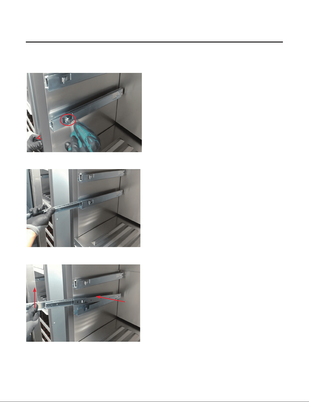
12. How to Disassemble Slide Rail
1) Remove the Shelf
2) Remove 1 Screw
3) Pull Slide Rail to the end
4) Raise it up and pull Slide Rail by this direction
5) Assembly is reverse order.
②
Pull in this direction
①
Raise it up
- 61 -
Copyright © 2018-2019 SIGNATURE KITCHEN SUITE.
All rights reserved. Only training and service purposes.
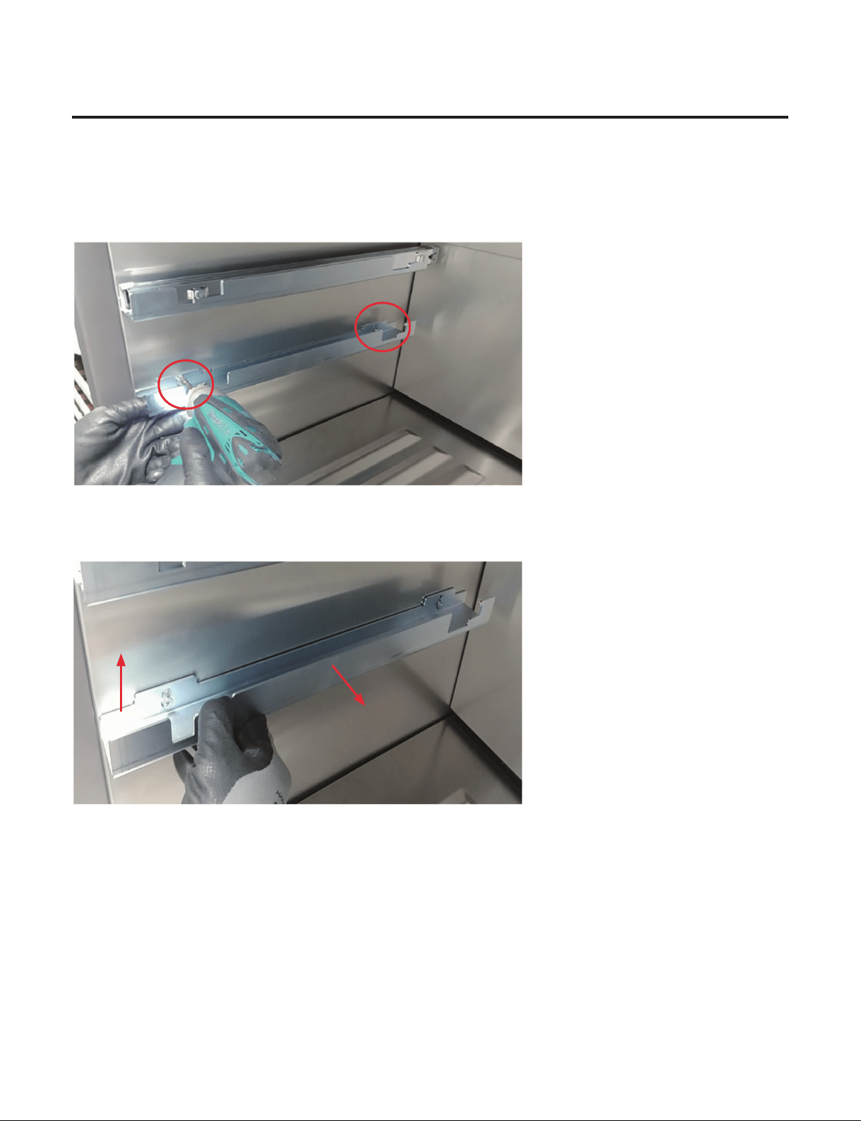
13. How to Disassemble Holder Rail
1) Remove the Shelf
2) Remove Slide Rail
3) Remove 2 Screw
4) Raise it up and pull Slide Rail by this direction
5) Remove 2 Screw completely
6) Assembly is reverse order.
②
Pull in this direction
①
Raise it up
- 62 -
Copyright © 2018-2019 SIGNATURE KITCHEN SUITE.
All rights reserved. Only training and service purposes.
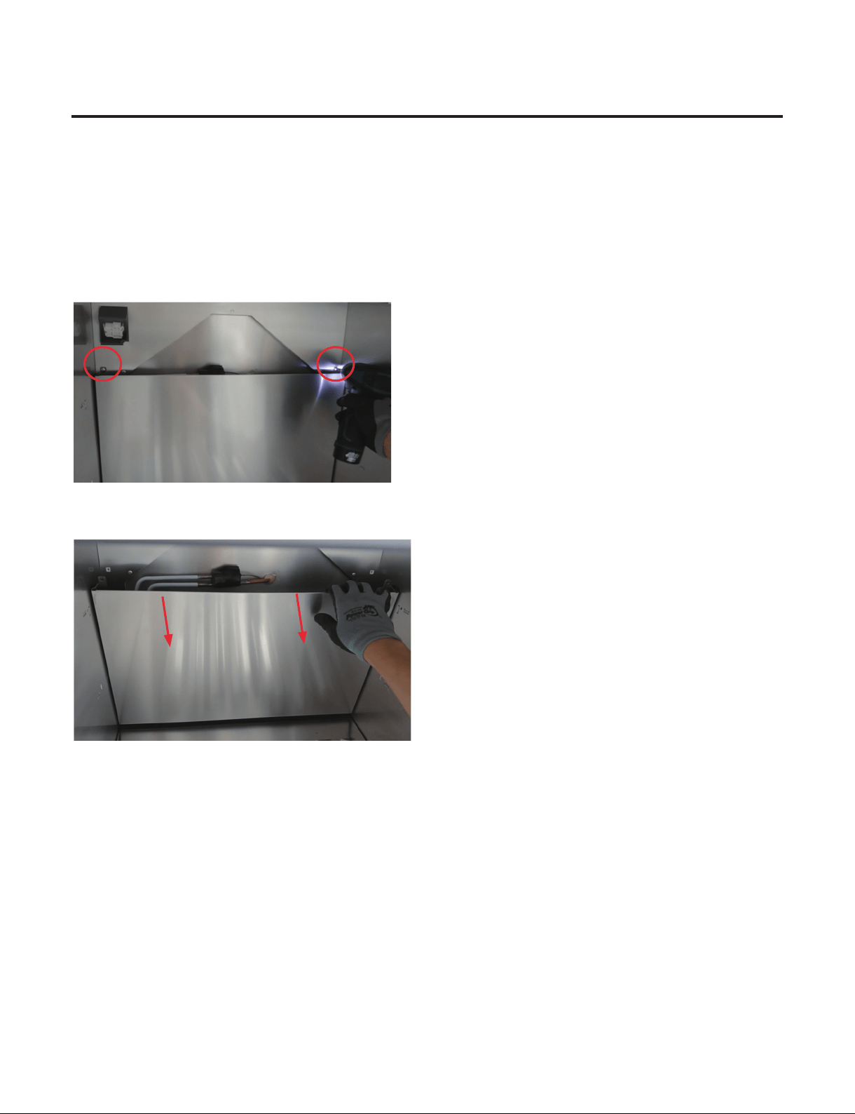
14. How to Disassemble Top Duct
1) Remove 3 Cap Covers (18inch - 2 Cap Covers)
Location of Cap covers and Screws Location of Cap covers and Screws
2) Remove 3 (or 2) Screws
3) Pull down the Top Duct and Separate the Housing and Remove the Top Duct
4) Assembly is reverse order.
- 63 -
Copyright © 2018-2019 SIGNATURE KITCHEN SUITE.
All rights reserved. Only training and service purposes.
15. How to Disassemble Grille Fan
1) Remove Shelf
2) Remove Slide Rail and Holder Rail
3) Remove Control Panel and Top Duct
(When disassembling the Top Grille Fan)
4) Remove 2 screws
5) Pull Upper side of the Grille Fan
6) Separate the Housing and Disassemble the Grille Fan
7) Assembly is reverse order.
(Middle and Lower Grille Fan)(Top Grille Fan)
- 64 -
Copyright © 2018-2019 SIGNATURE KITCHEN SUITE.
All rights reserved. Only training and service purposes.
16. How to Disassemble Multi Duct
1) Remove Shelf
2) Remove Slide Rail and Holder Rail
3) Remove Control Panel and Top Duct
(When disassembling the Top Grille Fan)
4) Remove Grille Fan
5) Remove 2 screws
6) Pull Upper side of the Multi Duct and Disassemble the Multi Duct
7) Assembly is reverse order.
- 65 -
Copyright © 2018-2019 SIGNATURE KITCHEN SUITE.
All rights reserved. Only training and service purposes.
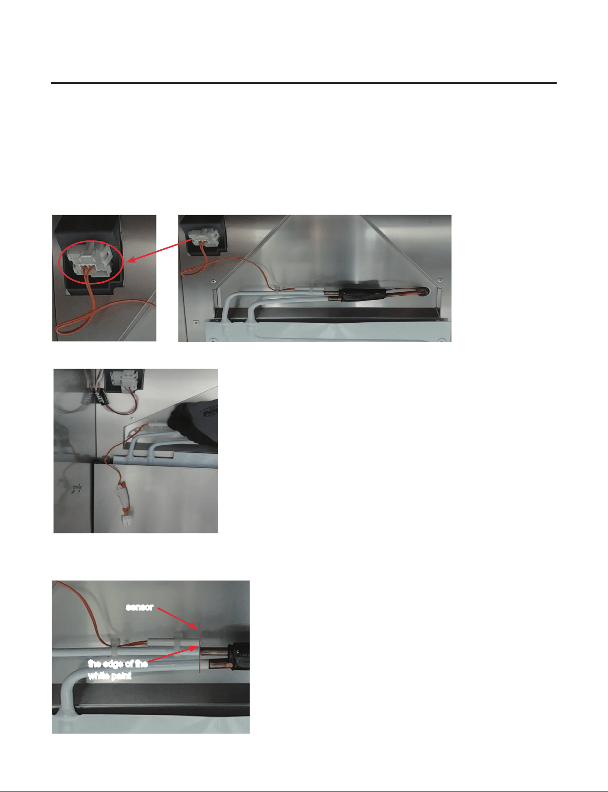
17. How to Disassemble Defrost sensor
1) Remove Shelf
2) Remove Slide Rail and Holder Rail
3) Remove Control Panel and Top Duct
(When disassembling the Top Grille Fan)
4) Remove Grille Fan and Multi Duct
5) Separate the Housing
6) Pull the sensor backward
7) Assembly is reverse order.
※
When assembling the sensor, assemble the tip of the sensor to the edge of the white paint.
the edge of the
white paint
sensor
- 66 -
Copyright © 2018-2019 SIGNATURE KITCHEN SUITE.
All rights reserved. Only training and service purposes.
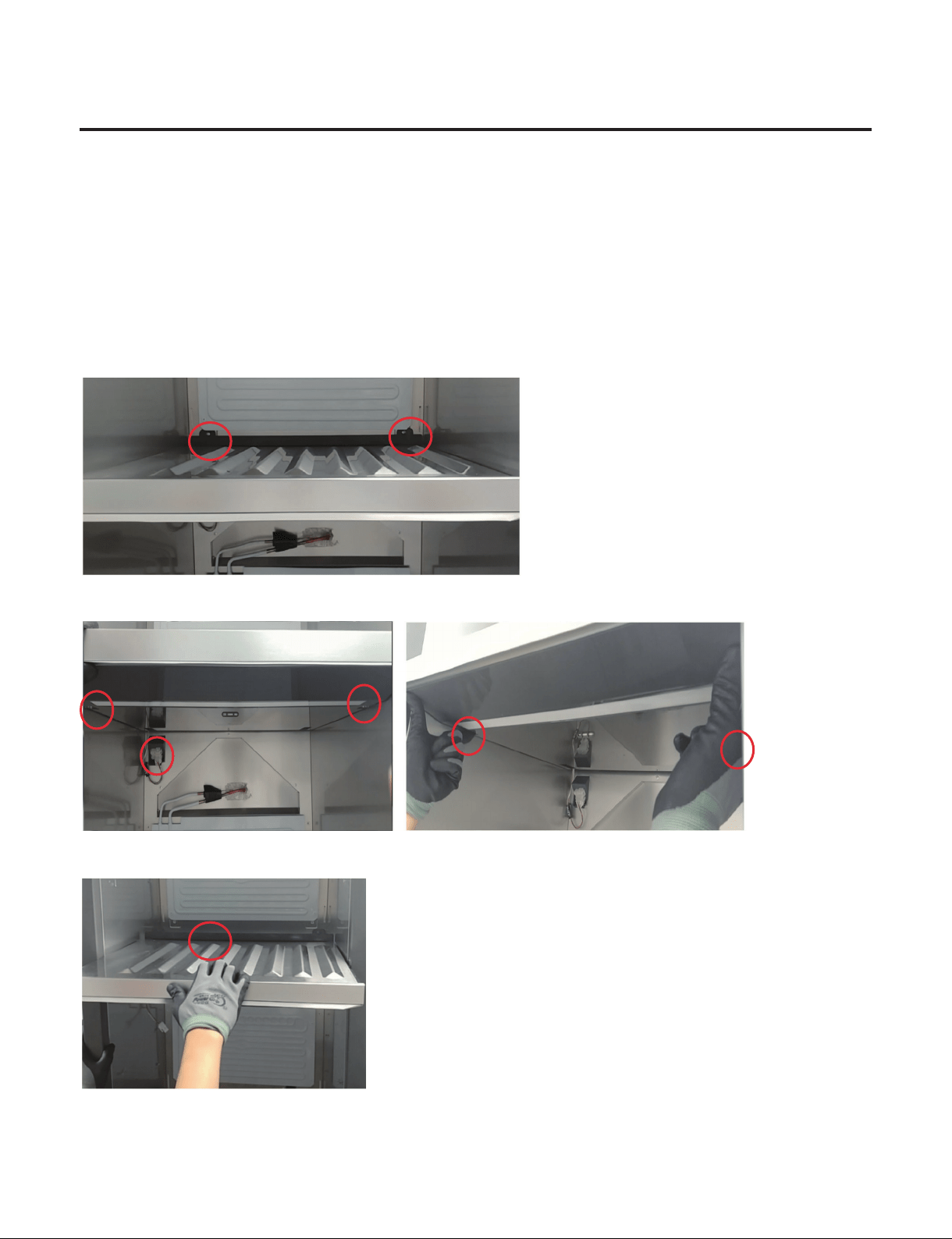
18. How to Disassemble Barrier
1) Remove Shelf
2) Remove Slide Rail and Holder Rail
3) Remove Control Panel and Top Duct
(When disassembling the Top Grille Fan)
4) Remove Lower Grille Fan and Upper Multi Duct
(Based on the Barrier you want to disassemble)
5) Remove 2 screws
6) Separate the Housing and Push 2 Rack
7) Pull Barrier and Disassemble the Barrier
8) Assembly is reverse order.
- 67 -
Copyright © 2018-2019 SIGNATURE KITCHEN SUITE.
All rights reserved. Only training and service purposes.
9. Sealed System Repair Method of Refrigerator with R600a Refrigerant
9-1.Outline
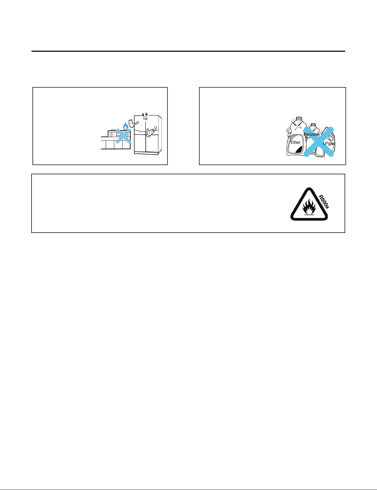
9-1-1. Safety warnings and cautions before Sealed System Repair
Keep away ame.
There is a risk of re.
Do not store inammable
ether,benzene,alcohol,chemicals,LP
gas,etc.in the refrigerator
There is a risk of
explosion or re.
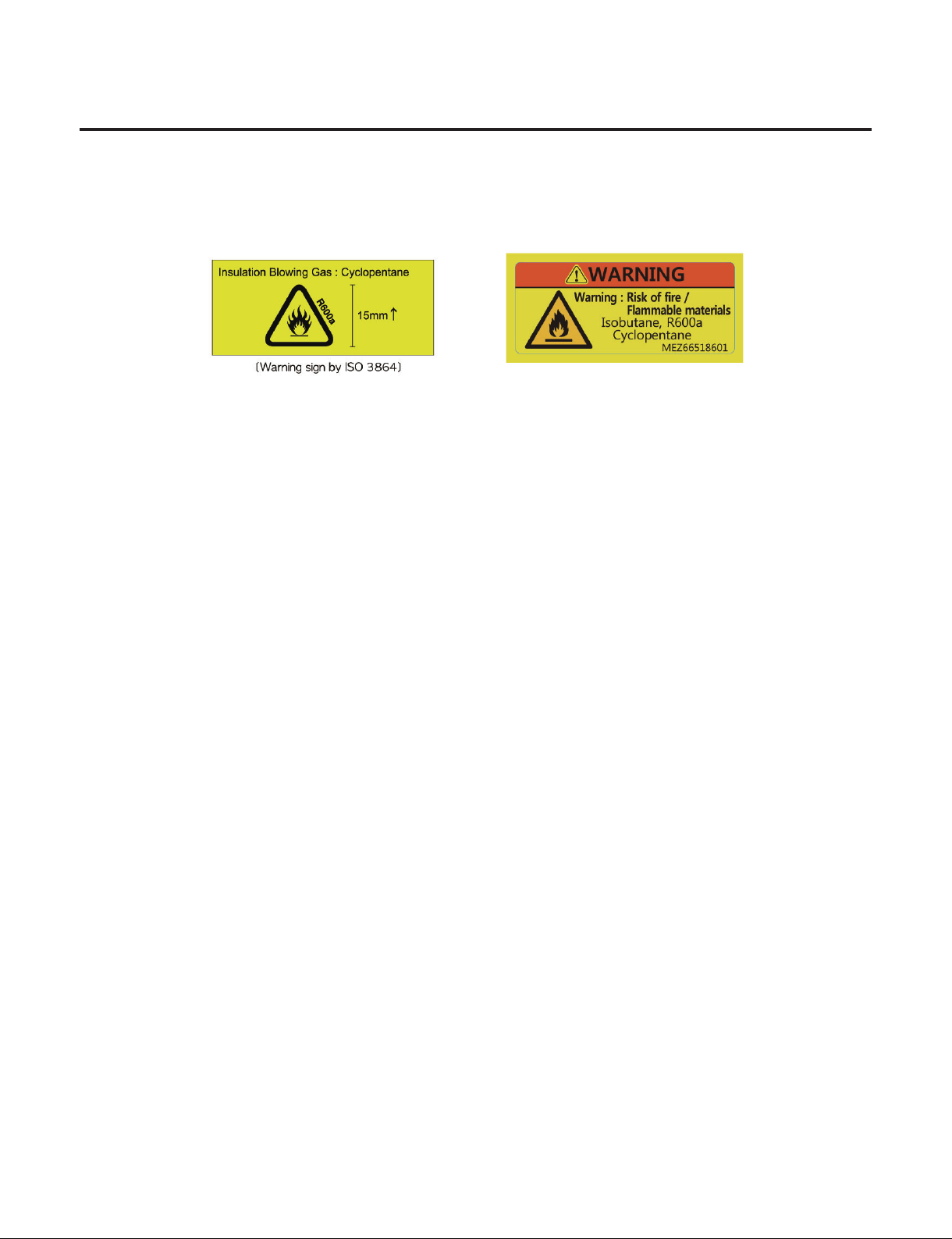
9-1-2. Checkpoints before Sealed System Repair
Open the Cover ASM,Back-M/C of refrigerator and check the type of refrigerant indicated on a compressor
before starting work.A yellow label is adhered to the compressor for the refrigerator using R600a as refrigerant.
9-1-3. Features of R600a Refrigerant
·
Non-polar natural gas refrigerant (CH(CH3)3)
·
Since R600a is same series as butane gas,there is danger of re when discharged into air at appropriate
concentration (extreme handling is required for sealed system repair of cycle).
Explosion concentration:1.8%~8.4%/Vol.
Burning temperature:494 ° C
9-1-4. Features of R600a Refrigerator
·
With refrigerant quantity of 60%or so for the refrigerator using R134a as refrigerant
·
Large vacuum level at suction pressure (at low pressure side)
·
COMP capacity of the refrigerator using R600a as refrigerant is large by 1.7 times than that of the refrigerator using R134a.
·
Labels as in Figure are displayed at the compressor of a refrigerant for R600a and the back plate of refrigerator.
Be careful about the ventilation during the repair of refrigerator cycle.
R600a refrigerant is inammable,so make sure to remove heat source or ame during the
work.(Smoking is strictly prohibited.)
- 68 -
Copyright © 2018-2019 SIGNATURE KITCHEN SUITE.
All rights reserved. Only training and service purposes.
9-1-5. Location and Environment for Sealed System Repair
·
Check that drafting and air ventilation are well done at a working area and perform work after making drafting and
air ventilation smooth (use refrigerant return bag indoors).
·
Check that there are re appliances or heating source around the working area and then remove them before work.
·
Since R600a refrigerant is very inammable,they should not be discharged indoors.
·
Be sure to follow sealed system repair SVC procedures during work.
9-1-6. Sealed System Repair Work Tool
·
R600a refrigerant
·
Bombe
·
Pinch Plier
·
Hoses
·
Refrigerant Return Bag
·
Vacuum Pump
·LokRing Tool
·
Charging Tube
·
Leakage Tester
·
Drier

- 69 -
Copyright © 2018-2019 SIGNATURE KITCHEN SUITE.
All rights reserved. Only training and service purposes.
9-2. Sealed System Repair SVC Method
For the sealed system repair of R600a type of refrigerator,perform work according to following SVC method.
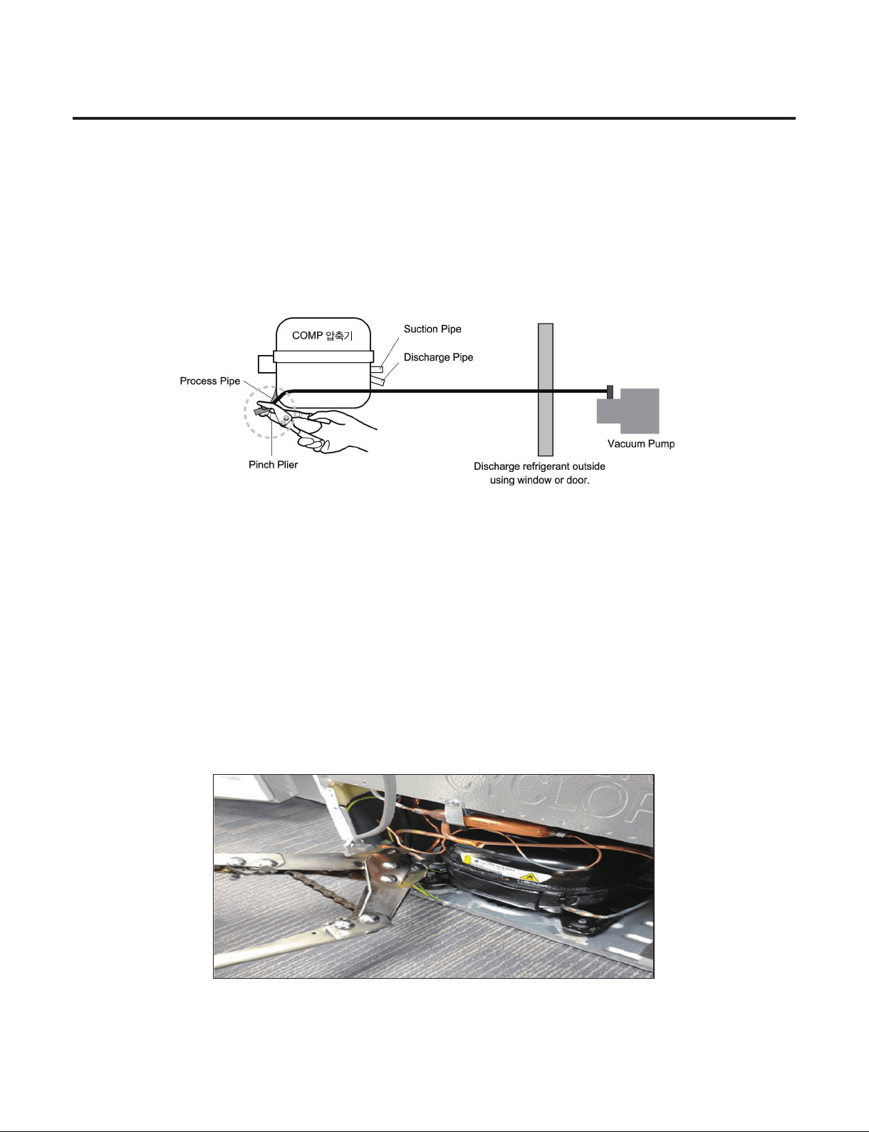
9-2-1. Return of Refrigerator Refrigerant
Required equipment:Pinch pliers,refrigerant discharging hose,refrigerant return bag
• Take power cords out and remove power between 6sec through 12sec after powering ON to open all both sides of 3way
valve.
• Leave doors of a refrigerator so that they are not closed.
• Connect pinch pliers with a refrigerant discharging hose.
• Place the outlet of a refrigerant discharging hose outside.
(Remove re appliances or heating sources near a refrigerant discharging hose.)
• Always use a refrigerant return bag for working at the contained space.
• Bore the charging pipe of a compressor with pinch pliers.
(Remove re appliances or heating sources near a refrigerator.)
• Perform refrigerant discharge for more than 7 minutes.
- 70 -
Copyright © 2018-2019 SIGNATURE KITCHEN SUITE.
All rights reserved. Only training and service purposes.
9-2-2. Return of Remained Refrigerant
Required equipment:Pinch pliers,hose for refrigerant recovery,vacuum pump
• If refrigerant return time of 7 minutes has passed,connect a vacuum pump at the ends of a refrigerant return hose outdoor.
(Vacuum pump must operate outdoor.)
• Operate a vacuum pump in order to return refrigerant remained in the pipe.
• Vacuum working time should be for more than 10 minutes.
9-2-3. LokRing Repair Step
• Required equipment: LokRing Tool
• Remove pinch pliers if remaining refrigerant return is completed.
• Cut the front part of a process pipe with a cutter.(Check that remaining refrigerant comes out.)
• Perform LokRing SVC work such as replacement of compressor and dryer,or repair of leakage part.
- 71 -
Copyright © 2018-2019 SIGNATURE KITCHEN SUITE.
All rights reserved. Only training and service purposes.
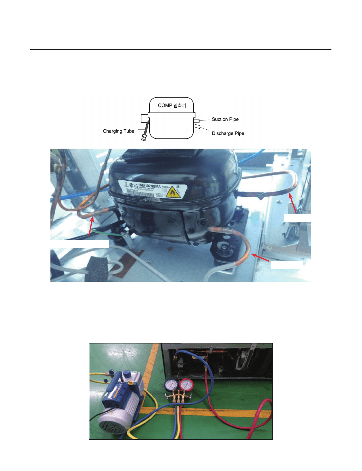
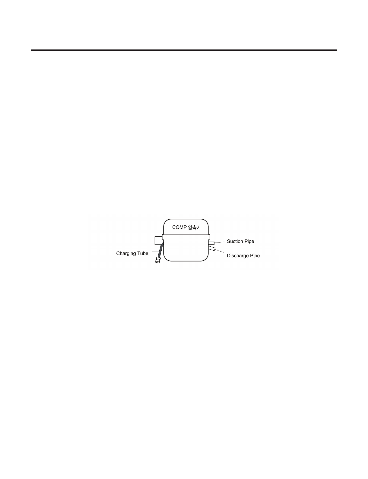
9-2-4. Charging Tube Connection Step
Required equipment:Charging tube,LokRing Tool
• Remove a charging pipe to recharge R600a refrigerant after completing work,and then connect a charging tube with LokRing.
Processing(Charging)
Discharge
Suction
9-2-5. Vacuum Air Removal
Required equipment:Vacuum pump
• Connect a vacuum pump to a charging tube to perform vacuum cycle.
• Vacuum work should be performed for an hour.(If vacuum time is short,normal cooling performance may not be exerted due to
failure of cooling cycle.)
- 72 -
Copyright © 2018-2019 SIGNATURE KITCHEN SUITE.
All rights reserved. Only training and service purposes.
9-2-6. Refrigerant Charging
Required equipment:Bombe,R600a refrigerant (75g)
• First remove re appliances and heating source for performing work when charging scaled refrigerant.(Do not spray
refrigerant indoor.)
• Measure the accurate quantity (75g)of refrigerant to charge it into a Bombe.
• Make the Bomber as vacuum status to charge refrigerant. (If there is air or moisture in a Bombe,it may give effect on
performance of a cooling cycle.)
• Please manage refrigerant quantity as 75g11.Different from R134a,R600a gives much effect on cooling performance
depending on change of refrigerant quantity.
♦ GR-1137GPNM Model uses refrigerant 42g
♦ GR-3137GPNM Model uses refrigerant 44g
Refrigerant quantity =Weight after charging -Weight before charging (weight of vacuumed Bombe)
• Connect Bombe with a charging tube to charge refrigerant.
• Turn on power of refrigerator to operate a compressor.
• Measure Bombe weight after 5 through 10 minutes to check remained refrigerant quantity to complete charging of refrigerant.
(After charging refrigerant,never perform welding work or work using re appliances.)
9-2-7. Leak Inspection and Cycle Check
Required equipment:Leakage checking machine (foam and leakage inspection machine)
• Check f
or leakage by using form or a leakage inspection machine at the worked part if charging of refrigerant is completed.
• Check for leakage at the low pressure part with the compressor stopped,and check at the high pressure part with the
compressor being operating.
• If leakage is detected,proceed to repair according to repair process again starting from“2-1. Return of Refrigerator Refrigerant
”.(Never perform welding work or work using re appliances.)
• Check that h
eat remains at a discharge pipe or condenser with the hands if leakage check is completed.If heat
remains,the
cooling cycle is normal.(Take care since a discharge pipe may be hot.)
- 73 -
Copyright © 2018-2019 SIGNATURE KITCHEN SUITE.
All rights reserved. Only training and service purposes.
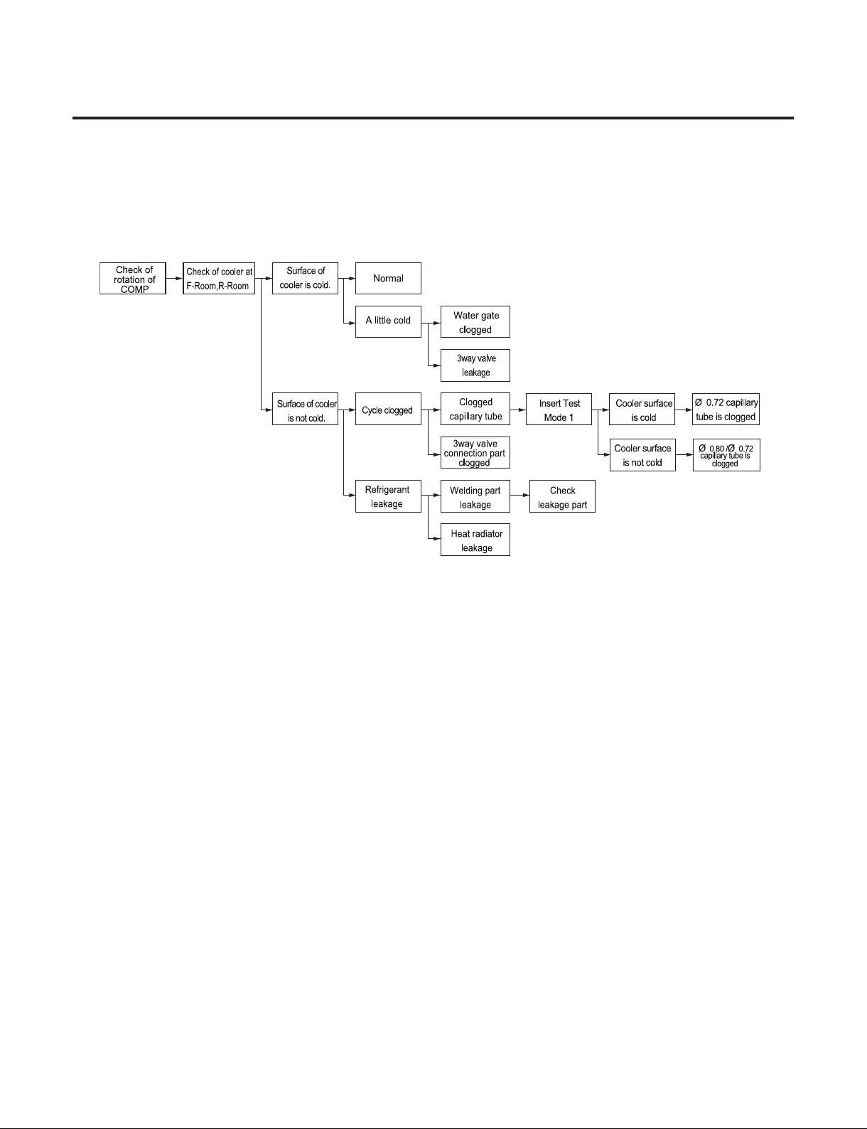
9-2-8.Failure Checking Procedures
- 98 -
- 74 -
Copyright © 2018-2019 SIGNATURE KITCHEN SUITE.
All rights reserved. Only training and service purposes.
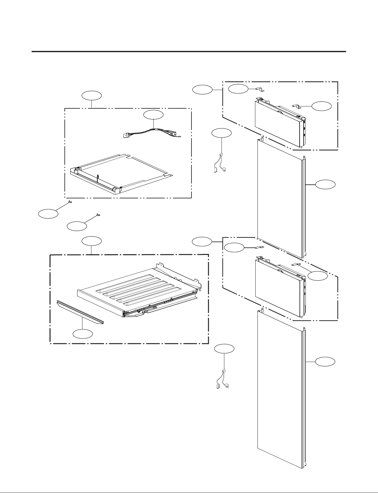
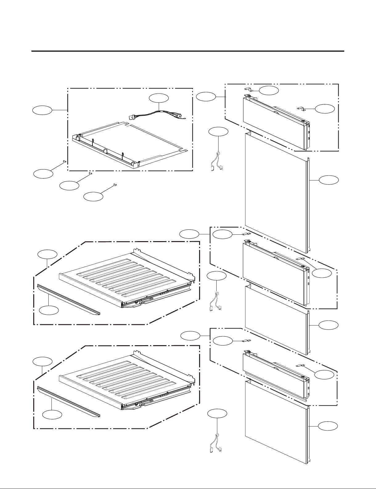
10. EXPLODED VIEW
206A
206A
206A
206A
206A
206A
248A
202A
203A
214A
213A
282A
283A
236A
236B
214A
500D
201A
500E
202A
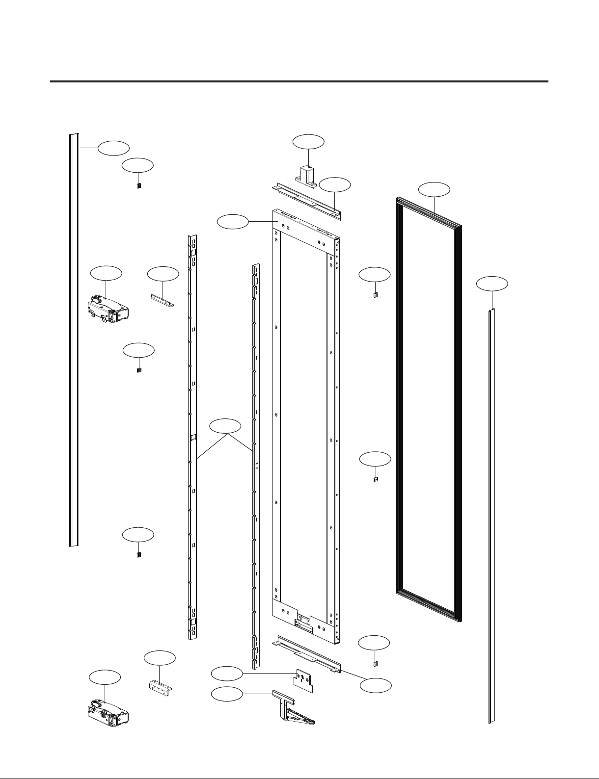
1. Door Part
#EV#
- 75 -
Copyright © 2018-2019 SIGNATURE KITCHEN SUITE.
All rights reserved. Only training and service purposes.
180E
181B
180F
192A
181D
180B
185A
190A
180D
302A
180A
610F
406G
500A
192A
#EV#
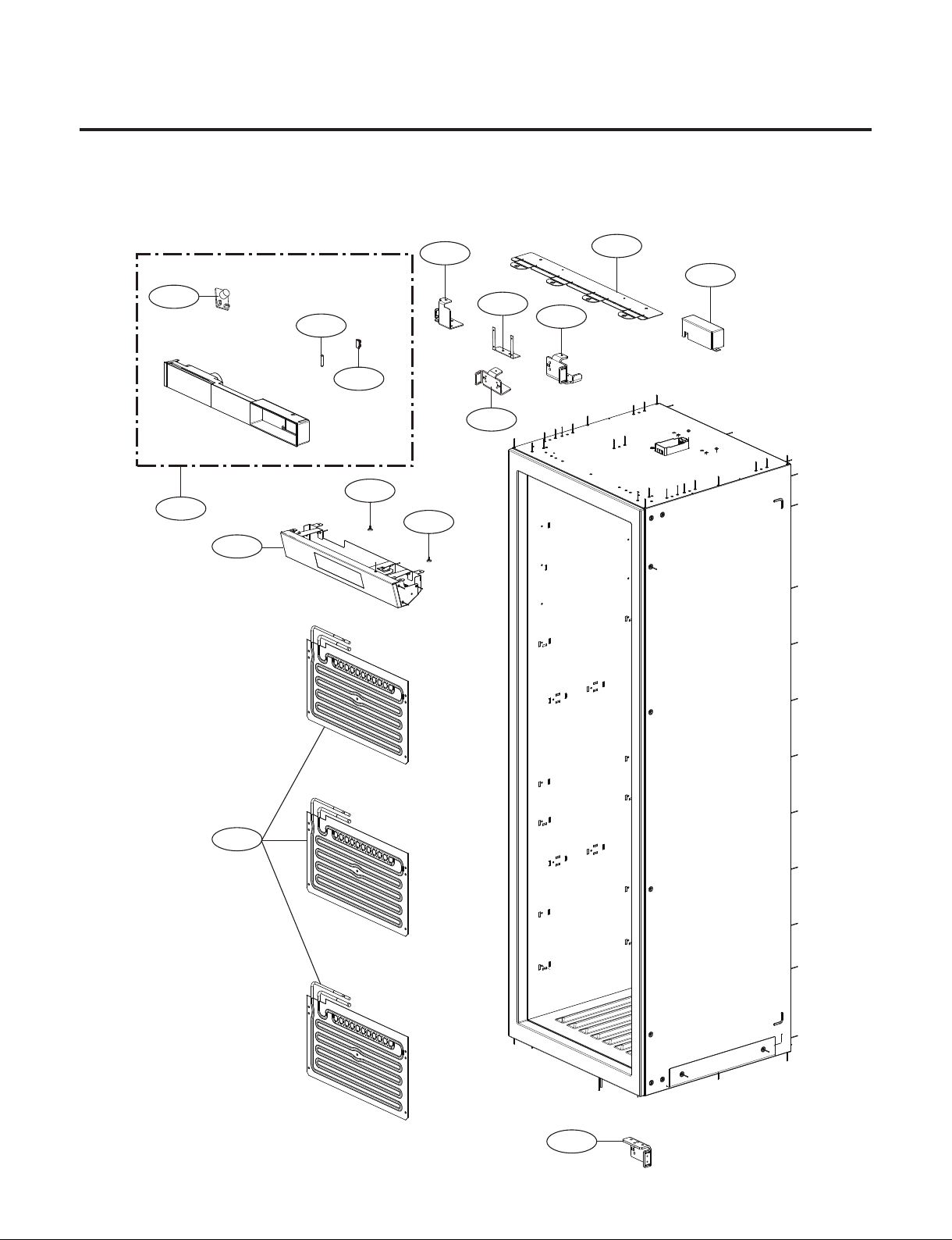
2. Case Part
Parts without a location number can be supplied as assembled unit
- SKSCW181RP : 2 Evaporator
- SKSCW241RP : 3 Evaporator
- 76 -
Copyright © 2018-2019 SIGNATURE KITCHEN SUITE.
All rights reserved. Only training and service purposes.
122D
121A
122E
122A
120A
181F
122B
120B
181F
125A
125A
610G
610H
610H
181E
181E
#EV#
3. Perform Part
Parts without a location number can be supplied as assembled unit
- Model : SKSCW181RP
- 77 -
Copyright © 2018-2019 SIGNATURE KITCHEN SUITE.
All rights reserved. Only training and service purposes.
3. Perform Part
Parts without a location number can be supplied as assembled unit
- Model : SKSCW241RP
122D
122D
121A
122E
122E
122A
120A
181F
181F
122B
122C
120C
120B
181F
181F
125A
125A
125A
610G
610H
610H
610H
181E
181E
#EV#
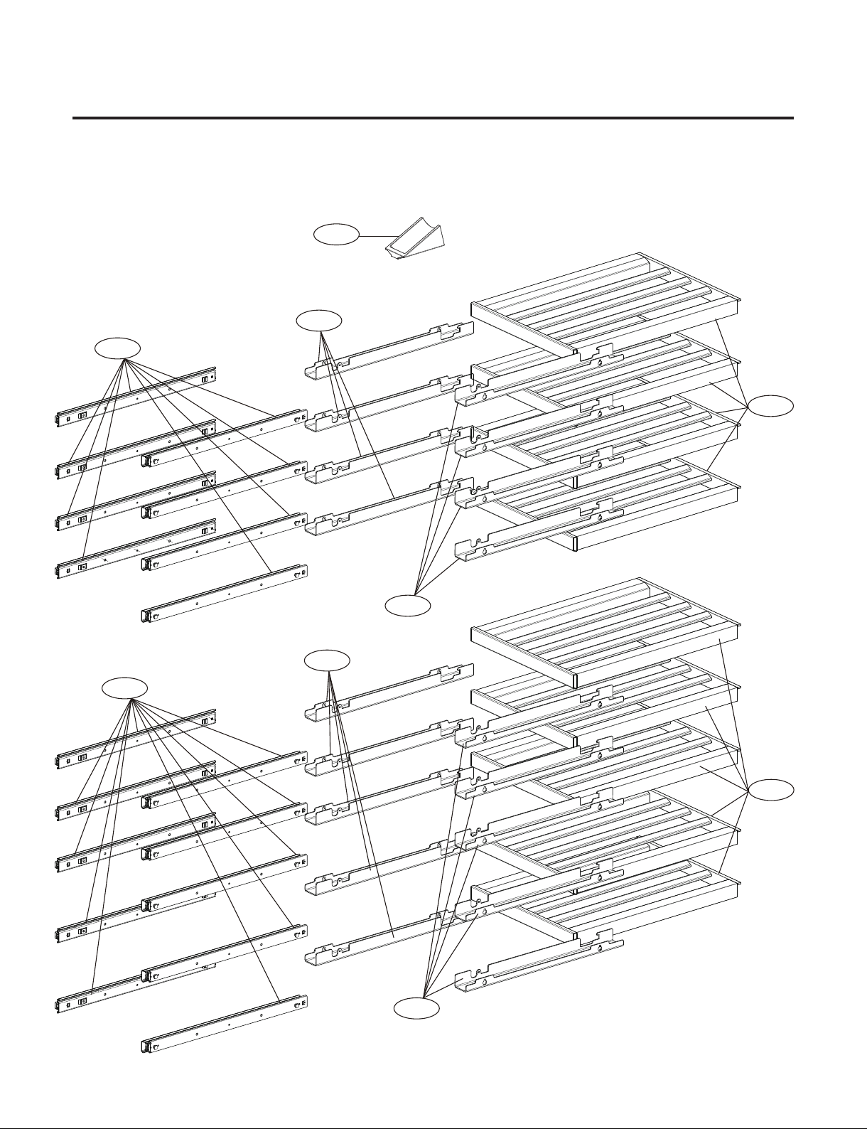
- 78 -
Copyright © 2018-2019 SIGNATURE KITCHEN SUITE.
All rights reserved. Only training and service purposes.
4. Movable Part
- Parts without a location number can be supplied as assembled unit
- Model : SKSCW181RP
147B
134A
144A
147A
144B
144A
144B
147A
134A
#EV#
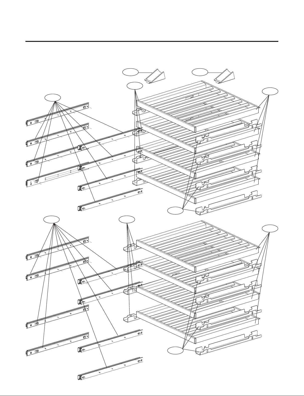
- 79 -
Copyright © 2018-2019 SIGNATURE KITCHEN SUITE.
All rights reserved. Only training and service purposes.
4. Movable Part
- Parts without a location number can be supplied as assembled unit
- Model : SKSCW241RP
147B
144A
147A
144B
147A
144B
147B
144A
134A
134A
#EV#
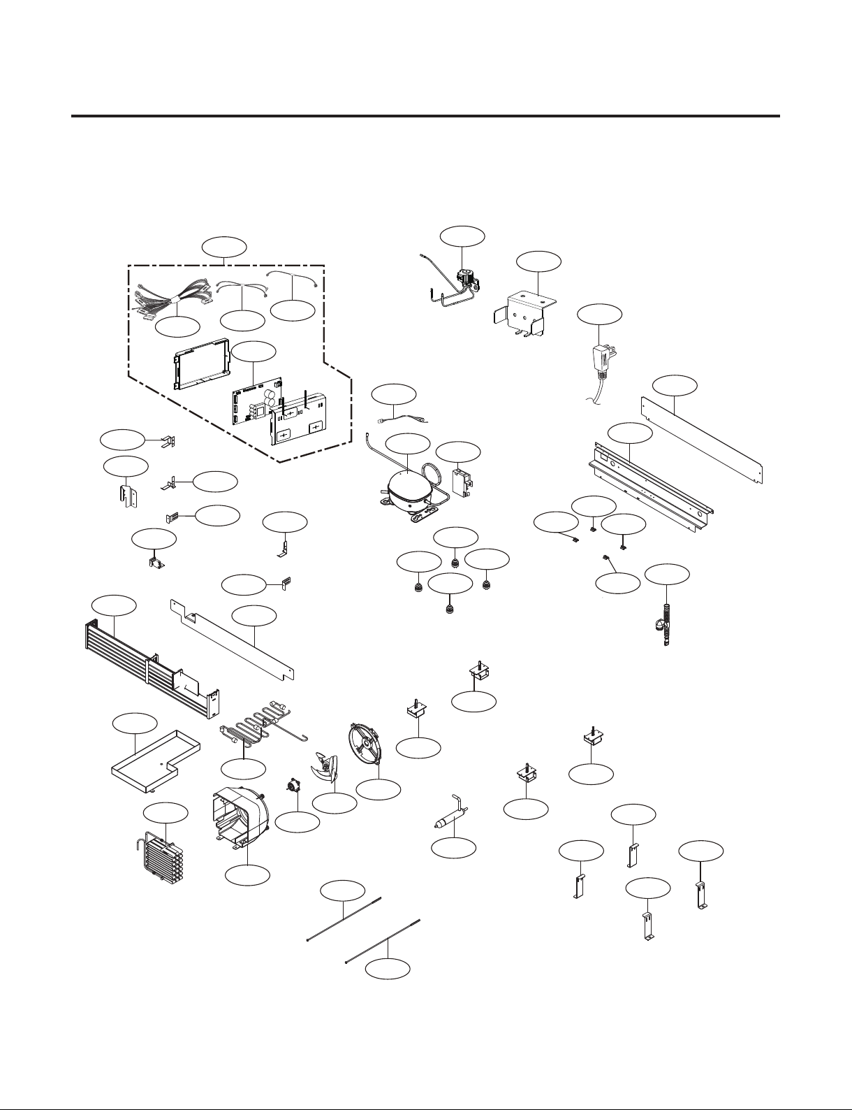
- 80 -
Copyright © 2018-2019 SIGNATURE KITCHEN SUITE.
All rights reserved. Only training and service purposes.
5. Machine Room Part
501B
501G
501F
501C
411A
619A
619B
174C
174A
173B
174B
175A
500C
174D
103A
319A
310B
308A
403B
308C
308B
104B
175A
104A
317A
104B
105A
171A
303D
314A
310A
314A
314A
314A
307A
171B
104A
301A
103B
173A
501H
194A
194A
194A
194A
306A
306A
306A
306A
#EV#
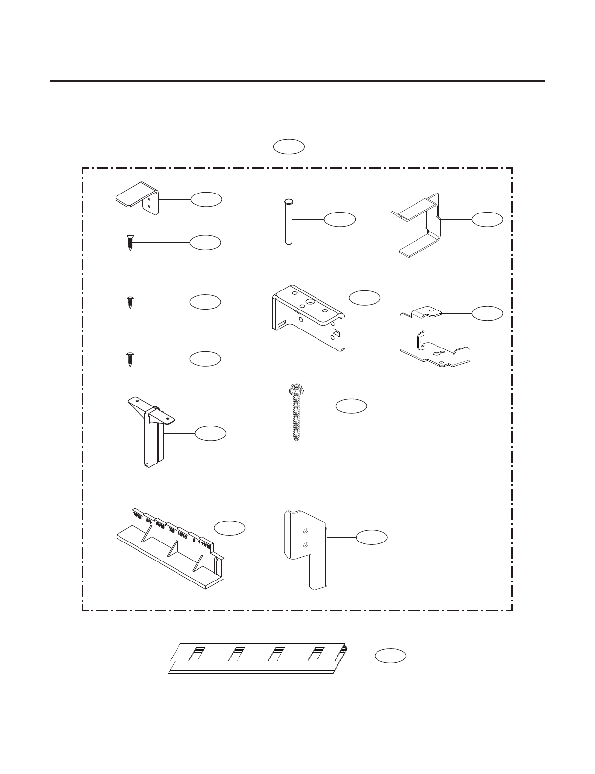
- 81 -
Copyright © 2018-2019 SIGNATURE KITCHEN SUITE.
All rights reserved. Only training and service purposes.
6. Installation Part
703A
704A
705A
180C
702A
702B
702C
700A
701A
709A
180G
706A
708A
710A
#EV#