Loading ...
Loading ...
Loading ...
8 www.dimplex.com
Opti-V Installation
Do not use cable with alumi-
num conductors.
!
NOTE: It is recommended that
all drywall installation and nish-
ing be completed after unit is fully
installed.
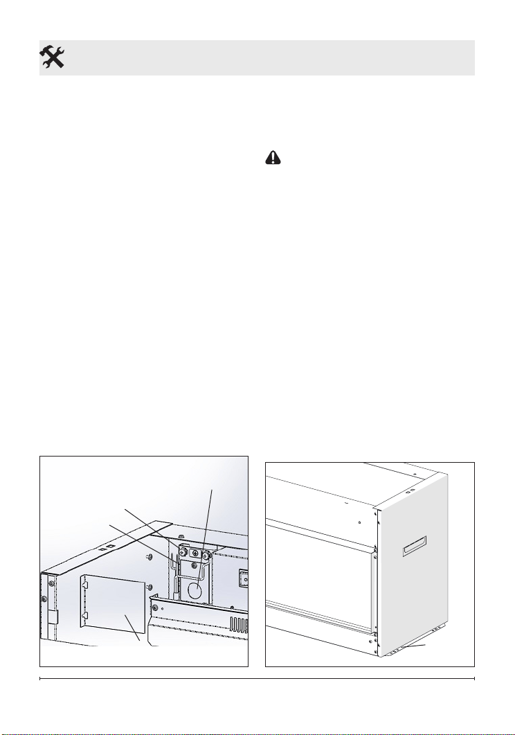
3. In the upper left hand corner
of the unit, loosen the two
securing screws and remove
the electrical cover panel.
(Figure 2)
4. Install a ⅜ in. (10 mm) or ½
in. (13 mm) cable connec-
tor, not included, suitable for
mounting in a ⅞ in. (22 mm)
hole, to the cable plate and
feed the supply cable through
the connector and secure.
5. Place the unit in the framed
opening, level with shims if
necessary and attach unit to
frame using mounting anges
provided (Figure 3).
CAUTION: When inserting
the unit take care not to damage
or pinch any of the power cables
that are concealed in the wall.
6. Remove the outer jacket and
strip the individual conductors
½ in. (1.3 cm) from the end.
7. Connect the black wire from
the unit to the Live (120V) or
Line 1 (240V) wire from the
power supply using a wire
connector (included).
8. Connect the white wire from
the unit to the Neutral (120V)
or Line 2 (240V) from the
power supply using a wire
connector (included).
Figure 2
Electrical
Cover Panel
Cable Clamp
Hole
Figure 3
Mounting
Flanges
Cable Plate
Grounding
Screw
Loading ...
Loading ...
Loading ...