Loading ...
Loading ...
Loading ...
9
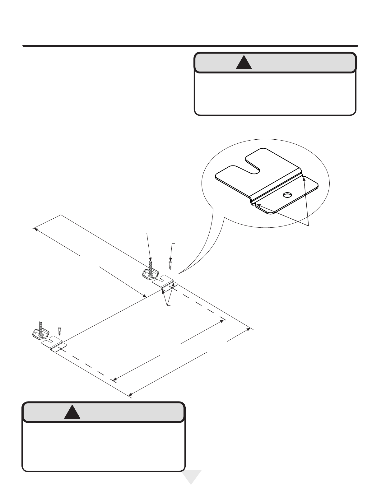
Figure 12
Figure 12a
FLOOR MOUNT ANTI-TIP BRACKET INSTALLATION
FREESTANDING APPLICATIONS ONLY
3) Make sure the appliance is in the desired location, then
mark on the oor the rear and both side corners of the
cabinet where the anti-tip brackets are to be installed.
If the installation does not allow marking the rear corner
of the cabinet, then make temporary lines on the oor
marking the front corner of the cabinet, excluding the
door. Slide the appliance out of the way. From the tem-
porary line extend the sidewall line back 21
1
⁄2 (54.6cm)
as shown in Figure 12.
4) Align the anti-tip brackets to the marks on the oor so
the sides of the brackets line up with the side of the cabi-
net marks, and the "V" notches on the anti-tip brackets
line up with the end of the 21
1
⁄2" (54.6cm) line (Rear of
cabinet line).
5) Fasten the anti-tip brackets to the oor using the sup-
plied
5
⁄16 x 1" lag screws with the
1
⁄2" socket or adjust
able wrench. (See Figure 12).
6) Slide the cabinet back into position, making sure the
rear cabinet leveling legs slide under the anti-tip brack-
ets engaging the slots.
"V" notches
in bracket
Rear of cabinet line
20
5
⁄8"
(52.4cm)
23
7
⁄8"
(60.7cm)
Side of cabinet line
Front of cabinet line
Rear Leveling
leg
5
⁄16 x1" Lag
Screw
"V" notches
in bracket
Tip Over Hazard
• Both rear cabinet leveling legs must be engaged
under the anti-tip brackets.
• Failure to install anti-tip brackets could result in
serious injury or death.
!
WARNING
EXCESSIVE WEIGHT HAZARD
Use two or more people to move
and stack product. Failure to do so can result
in back or other injury.
!
WARNING
21
1
⁄2 po
(54,6 cm)
Loading ...
Loading ...
Loading ...