
Loading ...
Loading ...
Loading ...
18
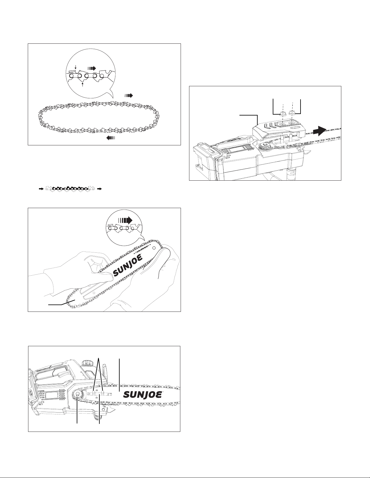
5. Starting at the tip, mount the chain drive links into the
bar groove, leaving a loop at the back of the bar. The
chain will loosely t until it is placed on the sprocket
(Fig. 19).
NOTE: Make certain of the direction of the chain
. If the chain is mounted
backwards, the saw will vibrate abnormally and will
not cut.
6. Mount the guide bar by inserting the studs into the long
slot on the guide bar; arrange the chain loop on the back
of the bar to ensure the sprocket is inserted in the loop
(Fig. 19).
7. Adjust the chain tension by pulling the guide bar + chain
forward, and make sure the chain is fully stretched. Using
your other hand, Fit the sprocket/chain end cover back
on by inserting the studs into the holes on the sprocket/
chain end cover. Replace the end cover nuts and screw to
tighten. (Fig. 20).
8. Lift up the guide bar tip slightly. Use the other end
of the hex key wrench/blade screwdriver to turn the
chain adjusting screw clockwise to tighten, turn it
counterclockwise to loosen (Fig.4).
NOTE: A new chain tends to stretch; check the chain
tension frequently, and adjust tension as required.
Chain Tension
Check the chain tension before using the saw when the chain
is cold. The correct tension of a cold chain is when there is no
slack on the underside of the guide bar; the chain is snug, but
you can rotate it by hand without binding.
During normal saw operation, the temperature of the chain
will increase. The drive links of a correctly tensioned warm
chain will hang approximately 0.050 in. (1.25 mm) out of the
bar groove (Fig. 21). Be aware that a chain tensioned while
warm, may be too tight upon cooling. Check the “cold tension”
before next use. The chain must be re-tensioned whenever the
ats on the drive links hang out of the bar groove (Fig. 21).
Fig. 17
Chain rotation
Sharp cutting edge
Chain drive link
R
Fig. 18
Loop
R
Fig. 19
Guide bar
Sprocket
Studs
Slot
Fig. 20
Sprocket/chain
end cover
End cover nuts
Pulling
forward
Loading ...
Loading ...
Loading ...