Loading ...
Loading ...
Loading ...
6
• Do not use any thread sealers on these water line t-
tings.
• Reverse osmosis, softened water, and de-ionized water
are not recommended as they will adversely affect the
quality of the ice.
Water
Supply
Line
Clamp and
Screw
Water valve
inlet
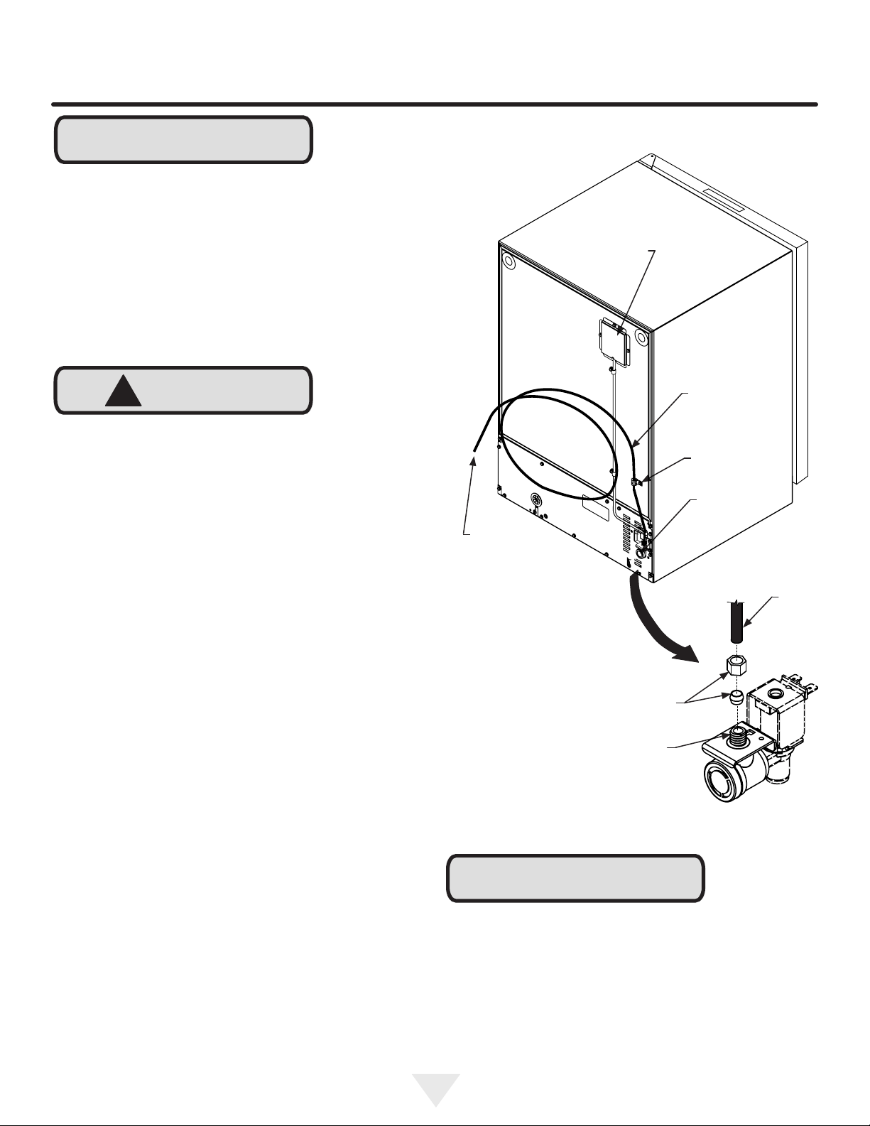
Figure 7
Back view of
ice machine
NOTE
NOTE
!
CAUTION
Water line from water valve
to ice-maker
INSTALLING THE WATER SUPPLY
MODEL ML24RI AND MODEL ML24RF WITH OPTIONAL ICE-MAKER KIT
Compression
tting
Water
supply
line
Water supply
service loop
to shut off
valve)
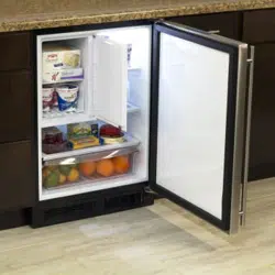
If you have model ML24RI you have a factory installed ice-
maker.
An optional ice-maker kit (part number S42418151) is avail-
able for model ML24RF which includes all of the necessary
parts for installation. The kit can be obtained from Marvel
customer service by calling 800-223-3900.
Water valve
inlet
Water Supply
Observe and follow all local building codes when installing
this appliance.
Use
1
⁄4" outside diameter copper tubing for your water sup-
ply which is available at any local hardware or plumbing
supply store. Bend the
1
⁄4" copper tubing to suit your instal-
lation being sure not to kink the tubing. Purchase enough
copper tubing length and coil it behind the unit to form a
"service loop" which will allow the appliance to be pulled
out from the installation for servicing or cleaning. Connect
the copper tubing to the "top side" of a cold water pipe to
prevent the ice-maker from plugging with sediment.
A shutoff valve is recommended on the water supply line to
ease servicing the appliance. NOTE: A SELF-PIERCING
TYPE VALVE IS NOT RECOMMENDED as they are prone
to clogging with sediment which will create pressure drop
reducing the water supply to the unit.
Connect the copper tubing water supply to the water valve
inlet with the compression nut tting provided. Secure the
water supply line to the back of the cabinet with the screw
and clamp provided in the corner of the back panel. (See
Figure 7).
Water pressure must be at a minimum of 20 psi for proper
operation and a maximum of 120 psi.
Make certain all water connections are watertight after in-
stallation. Form the tubing so that it will not vibrate against
the cabinet body or kink when your appliance is set in posi-
tion.
Loading ...
Loading ...
Loading ...