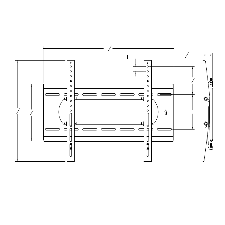
OUTDOOR TV
TILTING WALL MOUNT
INSTALLATION GUIDE
Model Number:
TW-5
26
1
4
"
20
5
16
"
11
7
16
"
25mm
1"
5
5
8
"
7"
1
15
16
"
WARRANTY REGISTRATION
REGISTER FOR
EXTRA BENEFITS
Activate within 30 days of purchase:
seura.com/activate
2
Prior to the installation of this product, read all
instructions. Keep this manual for future reference.
This product is designed to mount televisions and
any accessories weighing up to 200 lbs. to a vertical
CAUTION DO NOT EXCEED MAXIMUM LISTED
WEIGHT CAPACITY. SERIOUS INJURY OR PROPERTY
DAMAGE MAY OCCUR.
Warnings:
• Safety measures must be practiced at all times
during the assembly of this product. Use proper
safety equipment and tools for the assembly
procedure to prevent personal injury.
•
assembly procedure. Proper installation must
be followed as outlined in these installation
instructions. Personal injury and/or property
damage can result from dropping or mishandling
the TV.
• Ensure that there are no missing or defective
parts upon receipt. Never use defective parts.
• This product contains small parts that could be
a choking hazard.
•
of the television and the mount combined. A
professional installer or structural engineer
should inspect or verify the requirements of
the wall.
• Do not use this product for any purpose other
than to mount a VESA compliant TV on a vertical
surface as outlined in this manual.
• This product should not be mounted on metal
stud walls or cinder block walls.
• If drilling and/or cutting into the mounting
surface, always make sure that the wall is clear
of electrical wires. Cutting or drilling into an
electrical line may cause serious personal injury.
• Make sure there are no water or natural gas
lines inside the wall where the mount is to
be located. Cutting or drilling into a water or
gas line may cause severe property damage or
personal injury.
• Do not install near sources of high heat.
• Do not install on a structure that is prone to
vibration, movement or chance of impact.
Note: The included hardware is for mounting on
concrete, stone, brick, or wood studs . If you are
uncertain about the nature of your wall, please
consult your hardware or installation professional
for proper mounting to types of walls.
Safety
Compatible with Séura Outdoor TVs:
Shade Series: SHD1-55, SHD1-65, SHD1-75, SHD2-43, SHD2-55, SHD2-65, SHD2-75
Ultra Bright: STM3-55-U, STM3-65-U, STM3-86-U
WARNING: Cancer and Reproductive
Harm: www.p65warnings.ca.gov.
3
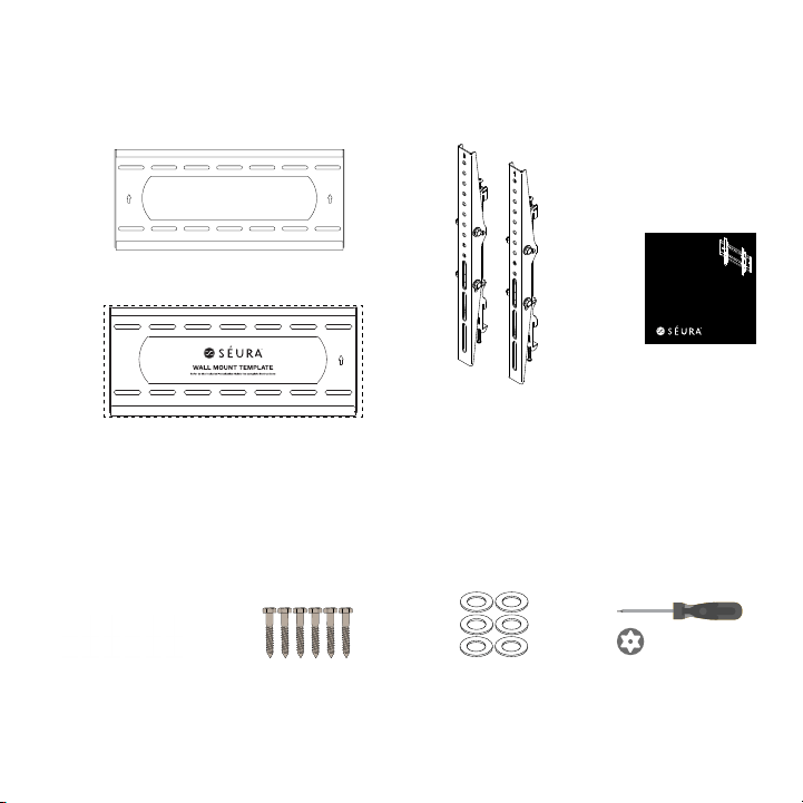
Manual
Wall Mounting Template
Mounting Plate
2 Tilt Mount TV
Brackets
Mounting Tools and Hardware
Parts Included
6 Stainless Steel Lag
Screws
5/16”, 3” long
P5080T
Installation Instructions
Visit the Premier Mounts website at http://www.premiermounts.com Page 3
Parts List
Installation Tools
The following tools may be required depending upon your particular installation. They are not included.
Pencil
Level
¼˝ Drill Bit for
Wood Stud
Electronic Stud Finder
Socket Wrench
Phillips Tip Screwdriver
Tape Measure
Hand Held Drill
Hammer**
3
/8 ˝ Concrete Drill Bit*
Protective Eyewear
* Optional tools for concrete installations.
½˝ Socket
M10 Socket*
2
1
5
/16
˝ x 3˝ Lag Bolts
(Qty 6)
Thread Depth Indicator
(Qty 1)
Universal Spacers
Finned Anchors
(Qty 6)
(Qty 24)
5
/16
˝ Flat Washers
(Qty 6)
Pro Mounting Hardware
Universal Washers
(Qty 6)
Security Barrel
(Qty 1)
Wall Plate
(Qty 1)
Universal Tilt Brackets
(Qty 2)
M6 x 60mm Screws
(Qty 2)
6 Plastic Anchors
3” long
For concrete, brick, and
stone installation only.
P5080T
Installation Instructions
Visit the Premier Mounts website at http://www.premiermounts.com Page 3
Parts List
Installation Tools
The following tools may be required depending upon your particular installation. They are not included.
Pencil
Level
¼˝ Drill Bit for
Wood Stud
Electronic Stud Finder
Socket Wrench
Phillips Tip Screwdriver
Tape Measure
Hand Held Drill
Hammer**
3
/8 ˝ Concrete Drill Bit*
Protective Eyewear
* Optional tools for concrete installations.
½˝ Socket
M10 Socket*
2
1
5
/16
˝ x 3˝ Lag Bolts
(Qty 6)
Thread Depth Indicator
(Qty 1)
Universal Spacers
Finned Anchors
(Qty 6)
(Qty 24)
5
/16
˝ Flat Washers
(Qty 6)
Pro Mounting Hardware
Universal Washers
(Qty 6)
Security Barrel
(Qty 1)
Wall Plate
(Qty 1)
Universal Tilt Brackets
(Qty 2)
M6 x 60mm Screws
(Qty 2)
6 Stainless Steel Flat
Washers
5/16”
P5080T
Installation Instructions
Visit the Premier Mounts website at http://www.premiermounts.com Page 3
Parts List
Installation Tools
The following tools may be required depending upon your particular installation. They are not included.
Pencil
Level
¼˝ Drill Bit for
Wood Stud
Electronic Stud Finder
Socket Wrench
Phillips Tip Screwdriver
Tape Measure
Hand Held Drill
Hammer**
3
/8 ˝ Concrete Drill Bit*
Protective Eyewear
* Optional tools for concrete installations.
½˝ Socket
M10 Socket*
2
1
5
/16
˝ x 3˝ Lag Bolts
(Qty 6)
Thread Depth Indicator
(Qty 1)
Universal Spacers
Finned Anchors
(Qty 6)
(Qty 24)
5
/16
˝ Flat Washers
(Qty 6)
Pro Mounting Hardware
Universal Washers
(Qty 6)
Security Barrel
(Qty 1)
Wall Plate
(Qty 1)
Universal Tilt Brackets
(Qty 2)
M6 x 60mm Screws
(Qty 2)
OUTDOOR TV
TILTING WALL MOUNT
INSTALLATION GUIDE
Model Number:
TW-5
26
1
4
"
20
5
16
"
11
7
16
"
25mm
1"
5
5
8
"
7"
1
15
16
"
26
1
4
"
20
5
16
"
11
7
16
"
25mm
1"
5
5
8
"
7"
1
15
16
"
26
1
4
"
20
5
16
"
11
7
16
"
25mm
1"
5
5
8
"
7"
1
15
16
"
26
1
4
"
20
5
16
"
11
7
16
"
25mm
1"
5
5
8
"
7"
1
15
16
"
26
1
4
"
20
5
16
"
11
7
16
"
25mm
1"
5
5
8
"
7"
1
15
16
"
Screwdriver
26
1
4
"
20
5
16
"
11
7
16
"
25mm
1"
5
5
8
"
7"
1
15
16
"
4
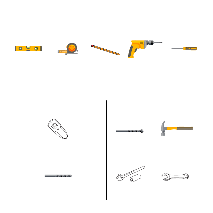
Parts and Tools Required (not included)
The following tools may be required depending on your particular installation. They are not included.
P5080T
Installation Instructions
Visit the Premier Mounts website at http://www.premiermounts.com Page 3
Parts List
Installation Tools
The following tools may be required depending upon your particular installation. They are not included.
Pencil
Level
¼˝ Drill Bit for
Wood Stud
Electronic Stud Finder
Socket Wrench
Phillips Tip Screwdriver
Tape Measure
Hand Held Drill
Hammer**
3
/8 ˝ Concrete Drill Bit*
Protective Eyewear
* Optional tools for concrete installations.
½˝ Socket
M10 Socket*
2
1
5
/16
˝ x 3˝ Lag Bolts
(Qty 6)
Thread Depth Indicator
(Qty 1)
Universal Spacers
Finned Anchors
(Qty 6)
(Qty 24)
5
/16
˝ Flat Washers
(Qty 6)
Pro Mounting Hardware
Universal Washers
(Qty 6)
Security Barrel
(Qty 1)
Wall Plate
(Qty 1)
Universal Tilt Brackets
(Qty 2)
M6 x 60mm Screws
(Qty 2)
1/2”
1/2”
1/2”
1/2”
Level
Stud Sensor
Tape Measure
7/32” Drill Bit
7/16” Masonry Drill Bit
Socket Wrench
½” Socket
Hammer
½” Combination
Wrench
Pencil Power Drill Philips #2
Screwdriver
(6mm Allen Wrench
for use with 86”
For Wood Stud Installation For Concrete, Brick and Stone Installation
1/2”
1/2”
1/2”
1/2”
1/2”
1/2”
5
26
1
4
"
20
5
16
"
11
7
16
"
25mm
1"
5
5
8
"
7"
1
15
16
"
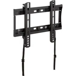
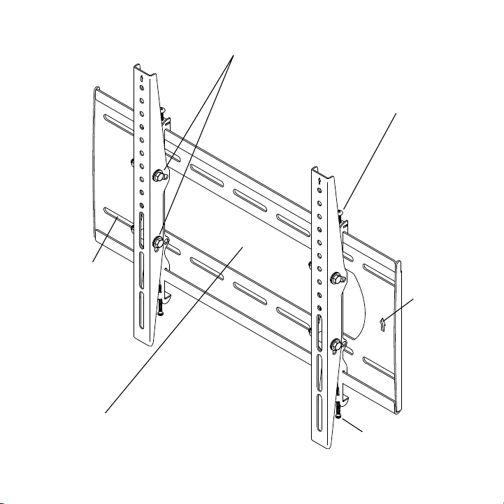
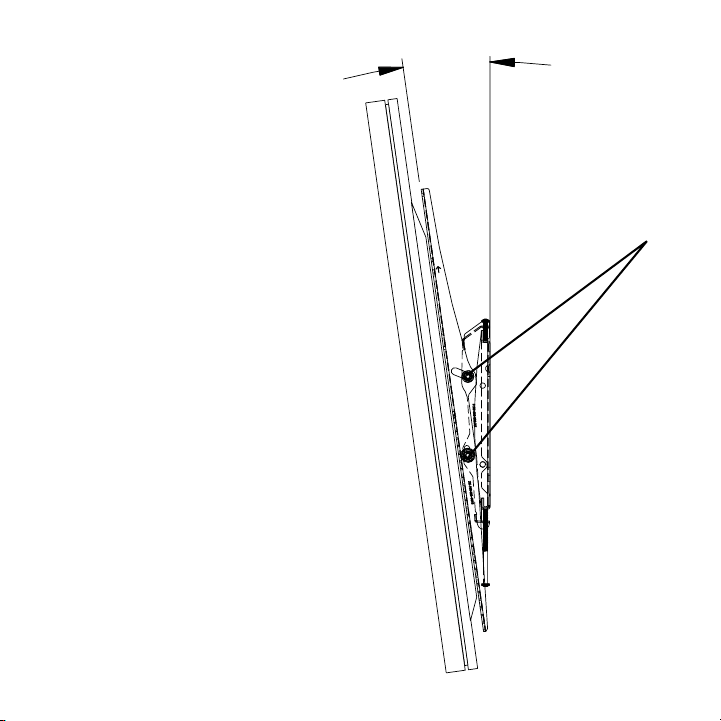
Top Leveling
Screws
Allows for leveling
adjustments of the
TV after mounting.
Tilt Locking Bolts
Allows for tilt
angle of the TV
adjustment.
Mounting Slots
Allow for a
variety of stud
and lateral shift
adjustments
when mounting
your TV.
Boom Locking Screws
Prevents the TV from being
removed or dislodged from
the mounting plate.
Cable/Electrical Cut Out
A large opening on the
mounting plate allows
for easy cable access
and power distribution
installations.
Directional
Mounting
Arrows
The arrow
lets you know
which edge
is up.
Features
6
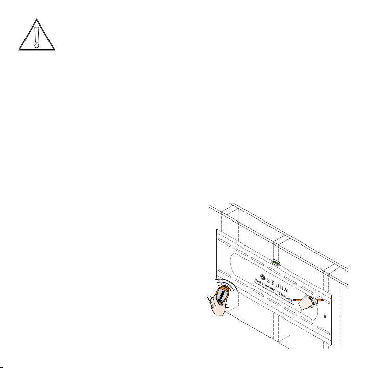
Installation
IMPORTANT: THIS PRODUCT MUST BE MOUNTED TO CONCRETE, STONE, BRICK OR WOOD STUDS. The wall
installer or structural engineer should inspect or verify the requirements of the wall.
2. Locate studs and mark the wall
All hole locations must be centered on wood studs.
Verify the center of the studs using an edge-to-
mark four hole locations in the template slots (2
fasteners instead of four.
IMPORTANT: HANDLE THE TV IN A VERTICAL POSITION TO AVOID DAMAGE TO THE
SCREEN. IF PLACING THE TV SCREEN-SIDE DOWN OR LEANING AGAINST A WALL DURING
INSTALLATION, COVER THE SCREEN WITH A PROTECTIVE CLOTH OR BLANKET.
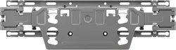
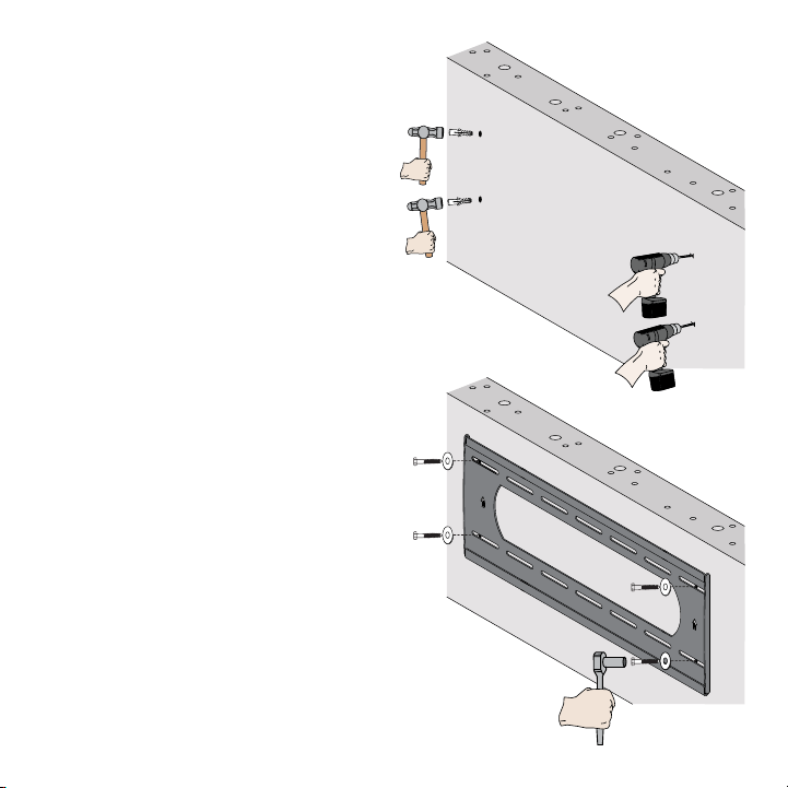
Step 1: Hang the Mounting Plate
Wood stud wall mounting:
See page 8 for mounting to concrete, stone or brick
1. Choose mounting location
page 14 for measurements from the edges of the TV to the
edges of the mounting template to properly place the template in the desired location on the wall. Note
that it is NOT vertically centered on the TV screen.

7
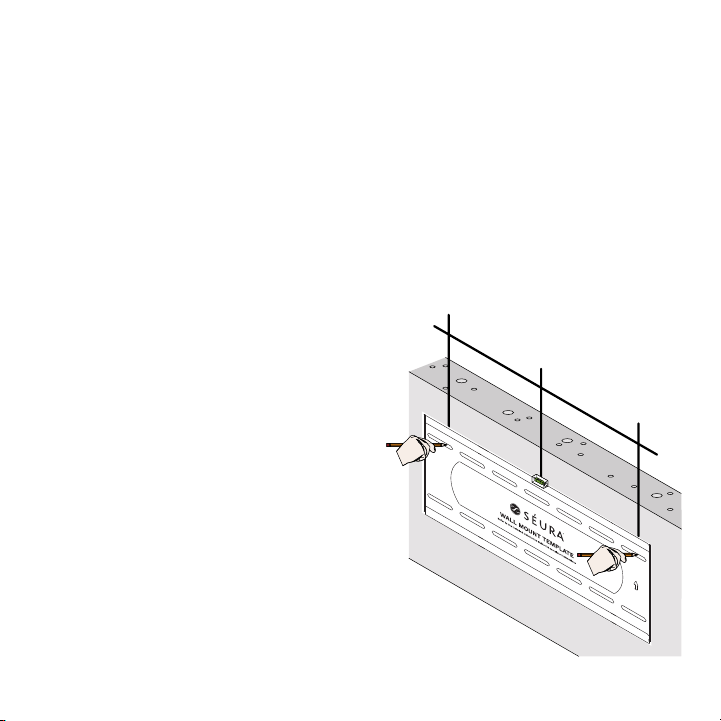
3. Drill pilot holes
Pre-drill the four marked holes on the wall 3-inches
deep with a 7/32” drill bit.
4. Aach mounting plate
Make sure the arrows on the mounting plate point
up. Align the mounting plate with the pre-drilled
holes. Attach mounting plate to wall using the
tighten the lag screws. Tighten the lag screws only
mounting plate.
8
2. Mark the wall
Level the template on the wall and mark four hole
with a pencil on the wall.
fasteners instead of four.
>12”
>12”
Concrete, stone or brick wall mounting:
See page 6 for mounting to a wood stud wall
1. Choose mounting location
page 14 for measurements from the edges of the TV to the
edges of the mounting template to properly place the template in the desired location on the wall. Note
that it is NOT vertically centered on the TV screen.
9
3. Drill pilot holes
Pre-drill the four marked holes on the wall 3-inches
deep with a 7/16” masonry drill bit. Insert a plastic
anchor into each of these holes. If necessary, lightly
tap each anchor into place with a hammer.
4. Aach mounting plate
Make sure the arrows on the mounting plate point
up. Align the mounting plate with the pre-drilled
holes. Attach mounting plate to wall using the four
screws using a socket wrench and ½” socket. Make
the concrete surface even if there is another layer
of material, such as drywall. Do not over tighten
the lag screws. Tighten the lag screws only until
plate.
10
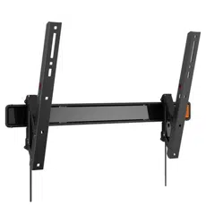
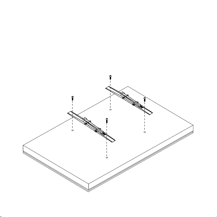
Step 2: Aach Tilt Mount TV Brackets to TV
TV with the arrows pointed towards the top of the TV. Line the brackets up with the VESA mount fastener
each Tilt Mount TV Bracket. Attach the Tilt Mount TV Brackets to the TV using the same four VESA mount
screws that you just removed.
26
1
4
"
20
5
16
"
11
7
16
"
25mm
1"
5
5
8
"
7"
1
15
16
"
11
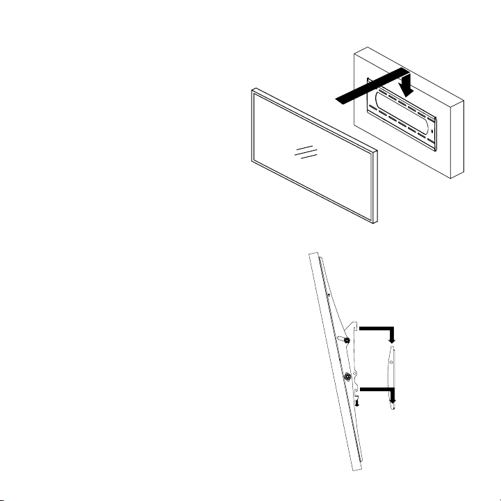
Step 3: Hang the TV
IMPORTANT: NEVER TRY TO HANG A TV BY YOURSELF. ALWAYS
USE AT LEAST TWO PEOPLE TO LIFT THE TV INTO PLACE.
This section requires two people.
that the top and bottom hooks of both mounting
brackets are securely seated on the upper and
lower mounting rails of the wall panel.
mounting rails on the wall panel.
the wall.
Connect the top and bottom mounting brackets to
the rails of the wall plate.
Attaching the Flat Panel to the Wall Plate
This section assumes that you have read and
understood these sections:
● Selecting the Proper Mounting Hardware
● Universal Washer Installation
● Universal Spacer Installation
surface.
1.
2.
3.
4.
1.
2.
3.
Identify the number and location of the thread
Align the holes on each mounting bracket with the
inserting a minimum of two (2) screws per bracket.
Do not overtighten the mounting hardware.
Proceed to the “Attaching the Flat Panel to the Wall
Plate” section.
Attaching the Mounting Bracket to the Flat Panel
26
1
4
"
20
5
16
"
11
7
16
"
25mm
1"
5
5
8
"
7"
1
15
16
"
1. Lift the TV and bring the back of the TV
towards the wall, positioning it slightly
above the mounting plate.
2. Lower the TV to hook the bottom hooks of
the Tilt Mount TV Brackets on the lower rail
of the mounting plate.
3. Bring the top of the TV closer to the wall
to hook the top hooks of the Tilt Mount TV
Brackets on the top rail of the mounting
plate.
4. Make sure the bottom and top rails are fully
engaged.
Do not let go of the TV until you are certain
that the top and bottom hooks of both
mounting brackets are securely engaged on
the upper and lower mounting rails of the
mounting plate.
12
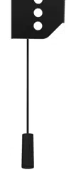
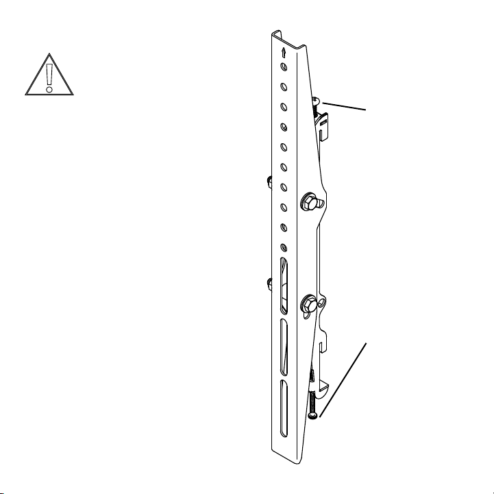
Top Leveling Screw
Allows for leveling
adjustments of the TV
after mounting.
Boom Locking Screw
Prevents the TV from
being removed or
dislodged from the
mounting plate.
Step 4: Adjust the TV
loosen hardware over time.
Top leveling screw adjustment:
located on the top of the tilt mount TV brackets will
allow you to compensate for this tilt by adjusting
screwdriver.
2. Adjust the tilt of your TV.
3. Tighten both leveling screws.
Do not overtighten the leveling screws.
Boom locking screw adjustment:
After you have adjusted leveling the TV, tighten the
Do not overtighten the locking screws.
26
1
4
"
20
5
16
"
11
7
16
"
25mm
1"
5
5
8
"
7"
1
15
16
"
Caution: It is possible to dislodge
your TV while you level it. Use
leveling and locking screws.
13
P5080T
Installation Instructions
Visit the Premier Mounts website at http://www.premiermounts.com Page 15
Leveling Screw Adjustment
If your at panel is tilted too far to one side, the leveling
screws will allow you to compensate for this tilt by
adjusting the screws with a screwdriver.
Loosen both locking screws.
®
Adjust the tilt of your at panel.
¯
Tighten both locking screws.
Caution!
It is possible to dislodge your at panel while you
level your at panel. Use extreme caution until
you tighten the locking screws.
Mounting Bracket Adjustments
Locking Screw Adjustment
After you have nished leveling your at panel, be sure
to tighten the two (2) M6 x 120mm locking screws.
Do not overtighten the locking screws.
M6 x 120mm
Locking Screw
(1 per Bracket)
M6 x 30mm
Leveling Screw
(1 per Bracket)
Tilt Adjustment
Adjusting the Flat Panel Friction Tilt Angle
Place one hand at the center-top edge of the at
panel.
®
Place the other hand on the center-bottom edge of
the at panel.
¯
Using the upper hand, gently pull the top of the
at panel towards you while the lower hand gently
pushes the bottom of the at panel away from you.
Adjusting the Flat Panel to the Original Position
Place one hand at the center-top edge of the at
panel.
®
Place the other hand on the center-bottom edge of
the at panel.
¯
Using the upper hand, gently push the top of the at
panel towards the wall while the lower hand gently
pulls the bottom of the at panel away from the wall.
Tilt adjustment:
Adjusting the TV Tilt Angle
1. Place one hand on the center-top edge
of the TV.
2. Place the other hand on the center-
bottom edge of the TV.
3. Using the upper hand, gently pull the top
of the TV towards you while the lower
hand gently pushes the bottom of the TV
away from you.
Adjusting the TV to the Original Position
1. Place one hand on the center-top edge
of the TV.
2. Place the other hand on the center-
bottom edge of the TV.
3. Using the upper hand, gently push the top
of the TV towards the wall while the lower
hand gently pulls the bottom of the TV
away from the wall.
After tilt is adjusted to the desired position,
Do not overtighten the tilt locking bolts.
Tilt
Locking
Bolts
14
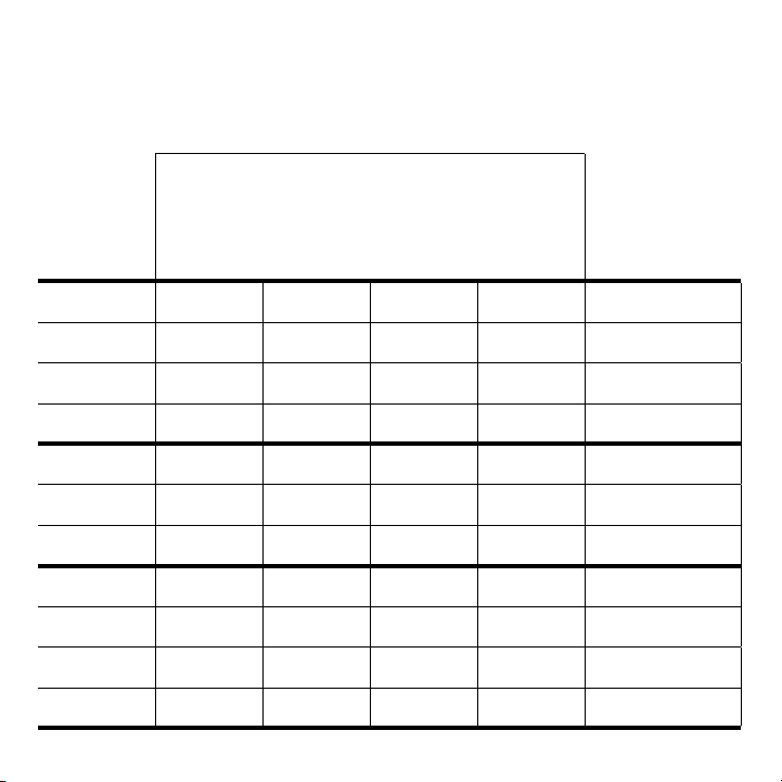
Séura Outdoor TV Mounting Measurement Guide
locate the mounting plate template in the desired location on the wall as described in Step 1. In addition,
use the bracket hole listed to determine which holes on the Tilt Mount TV Brackets to line up with the VESA
holes on the TV as described in Step 2.
Distance From Edges of TV to Edges of Mounting Template
TV Model
Top of TV
to Top of
Mounting
Template
Bottom of TV
to Bottom
of Mounting
Template
Left Edge
of TV to
Left Edge
of Mounting
Template
Right Edge
of TV to
Right Edge
of Mounting
Template
Top Tilt Mount TV
Bracket Hole
(line up with VESA
hole on back of TV in
7 3/4 in 6 7/8 in
Second hole down
from top
8 3/8 in 11 7/8 in 11 7/8 in
Second hole down
from top
11 11/16 in 10 13/16 in 16 3/16 in 16 3/16 in
Second hole down
from top
16 7/8 in 16 in 25 3/8 in 25 3/8 in
Second hole down
from top
SHD1-55 with
Soundbar
8 7/8 in 12 5/8 in 11 5/16 in 11 5/16 in
Second hole down
from top
SHD1-65 with
Soundbar
in 16 5/8 in 15 11/16 in 15 11/16 in
Second hole down
from top
SHD1-75 with
Soundbar
21 1/8 in 10 5/8 in 20 1/4 in 20 1/4 in
Second hole down
from top
SHD2-43 with
Soundbar
in in 5 13/16 in 5 13/16 in Top hole
SHD2-55 with
Soundbar
6 in 15 1/16 in 11 1/8 in 11 1/8 in
Second hole down
from top
SHD2-65 with
Soundbar
6 3/16 in
Second hole down
from top
SHD2-75 with
Soundbar
8 7/8 in 21 7/8 in in in
Second hole down
from top
15
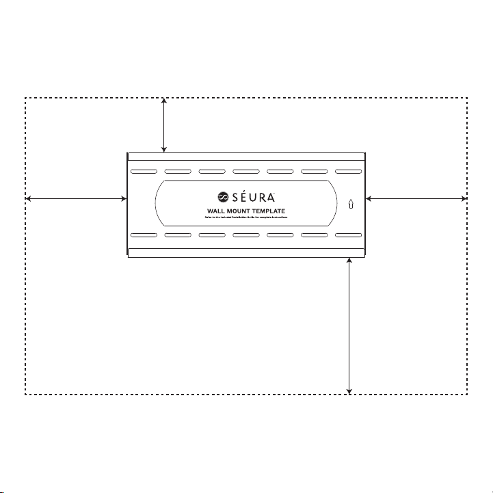
Example Wall Location
Shown for SHD2-55 with Soundbar
11 1/8 in 11 1/8 in
6 in
15 1/16 in
SHD2-55 with Soundbar Outline

16
Outdoor TV Mount Warranty
from time to time. Copies of the standard limited warranties
then in effect for a particular Product will be made available
https://www.seura.com/warranty/. This warranty is valid only
with respect to Product sales in the U.S. and Canada.
If any Product fails to work or operate properly because of a
such defect within the applicable warranty period indicated
commercially feasible, refund an amount equal to a pro rata
share of the current MSRP (as determined by the remainder
responsible for any costs related to installation and/or removal
of Product.
Product:
• Indoor and Outdoor Mounts
defects in original hardware and/or workmanship.
scratched or chipped paint or other surfaces.
Exceptions to Warranty: This warranty is valid only with respect
warrant Products against defects arising out of, related to, or
caused by, whether totally or partially, and whether directly or
indirectly, any of the following:
A. Failing to properly clean and maintain, any Product, part
or component of a Product, including, but not limited to,
commercial applications, where a Product is operating on
other conditions occurring during shipment of a Product or
pre-authorized packaging. Customer assumes all risk, and
costs, including transportation costs, while Product is in
D. Circumstances, damage or other conditions occurring
during unpacking and/or removal of a Product from its
original packaging, including the removal of protective
material;
a Product;
authorization;
G. The incorporation of a Product into or within a product
and ordinary operating instructions;
infestation, sand, mud, chemicals, improper cleaning agents
and other substances not intended to come into contact
with a Product, including any such substances contact with
a Product as the result of acts of God;
J. The improper or faulty installation, setup, or adjustment
of a Product;
service representative;
M. Corrosion that does not affect the performance of
a Product or the reasonable cosmetic appearance of a
Product (including without limitation, scratches or other
O. Normal wear and tear on the Product.
does not warrant its software or programs, or any content
downloaded after shipment. It is the purchaser responsibility to
take precautions to protect the product from malware, viruses,
data loss, and other potentially destructive programs.
Warranty Disqualiers.
Product and only covers a Product purchased new. All warranty
claims must be submitted together with original proof of
purchase and any Product subject to a warranty claim must
right to require any warranty claimant to produce the original
purchase receipt or other original purchase date proof as may

17
whose serial number has been removed, defaced, replaced, or
in its sole discretion, whether any product components are
defective and covered under warranty.
LIMITATION OF LIABILITY. THE EXPRESS LIMITED WARRANTIES
SET FORTH HEREIN ARE IN LIEU OF ALL OTHER WARRANTIES,
WRITTEN OR ORAL, EXPRESSED OR IMPLIED, INCLUDING,
BUT NOT LIMITED TO, ANY IMPLIED WARRANTIES OF
MERCHANTABILITY OR FITNESS FOR A PARTICULAR PURPOSE OR
USE. SÉURA WILL NOT BE LIABLE FOR ANY DAMAGE TO OTHER
PROPERTY CAUSED BY ANY DEFECT IN THE PRODUCT, DAMAGES
BASED ON INCONVENIENCE, LOSS OF BUSINESS OPPORTUNITY,
LOSS OF GOODWILL, INTERFERENCE WITH BUSINESS
RELATIONSHIPS, OR OTHER COMMERCIAL LOSS, EVEN IF
THE CUSTOMER HAS BEEN ADVISED OF THE POSSIBILITY OF
SUCH DAMAGES. SÉURA WILL NOT BE LIABLE FOR ANY LOSS,
DAMAGE OR LIABILITY OR ANY DIRECT, INCIDENTAL, INDIRECT,
PUNITIVE, SPECIAL OR CONSEQUENTIAL DAMAGES RESULTING
FROM THE USE OR MISUSE OF A PRODUCT, OR ARISING OUT
OF ANY BREACH, BY THE PURCHASER OF A PRODUCT, OF
THIS LIMITED WARRANTY. SÉURA SHALL NOT BE LIABLE FOR
ANY CLAIM AGAINST THE CUSTOMER BY ANY OTHER PARTY.
SÉURA SHALL NOT BE LIABLE FOR ANY VERBAL WARRANTY
ASSURANCES MADE BY ANY EMPLOYEE OR AUTHORIZED
DISTRIBUTOR, RESELLER OR INSTALLER THAT CONFLICTS
WITH OR ENHANCES THE WRITTEN WARRANTY HEREIN. SOME
STATES DO NOT ALLOW THE EXCLUSION OR LIMITATION OF
INCIDENTAL OR CONSEQUENTIAL DAMAGES, OR LIMITATIONS
ON HOW LONG AN IMPLIED LIMITED WARRANTY LASTS, SO THE
EXCLUSIONS MAY NOT APPLY TO A PARTICULAR PURCHASER.
NOTWITHSTANDING ANYTHING HEREIN TO THE CONTRARY,
WARRANTY CLAIM OR WITH RESPECT TO A PRODUCT SHALL
NOT EXCEED THE THEN CURRENT SÉURA WHOLESALE PRICE
OF THE SPECIFIC PRODUCT FROM WHICH THE CLAIM DERIVES.
NOTICE OF ANY WARRANTY CLAIM MUST BE RECEIVED BY
SÉURA, IN WRITING, PRIOR TO THE EXPIRATION OF THE
APPLICABLE WARRANTY PERIOD SET FORTH ABOVE. THE
PRODUCT WARRANTY APPLIES ONLY FOR THE PERIODS SET
FORTH ABOVE.
Warranty Procedure.
that the Product is not covered under the warranty or damaged
alternatives that are available on a fee basis.
Toll-Free Technical Support:
Representatives are available Monday-Friday, 8:00am-4:30pm
Central Time.
Onsite Service: If Technical Support determines the problem
work with the customer to schedule a convenient time for onsite
service is available in the United States during normal business
and special arrangements are made.
Factory Service: If Technical Support determines the Product
repaired Product to the authorized reseller, installer or
installation costs of Products.
Advanced Replacement: If Technical Support determines the
customer must follow return instructions below to send the
will be collected before shipment of the replacement Product.
removal or installation costs of Products.
Return Instructions:
be accepted for warranty claims if returned and shipped to
authorized replacement packaging. Packages not bearing the
original sales receipt for the purchase of the Product. All Product
Bay, WI 54311 with freight prepaid by the warranty claimant.
assumes and retains all such responsibility, any damage or loss
result of a warranty claim.
Exclusive Remedy. This Limited Warranty sets forth the
of a defective Product.
18
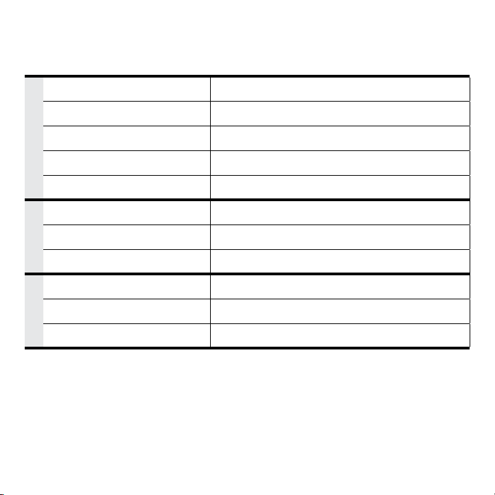
Specications
TILTING WALL MOUNT
Model: TW-5
GENERAL
DISPLAY COMPATIBILITY
MOUNTING PLATE DIMENSIONS
TILT +0° / - 7° to - 10°
FINISH COLOR Black Powder Coat
DURABILITY Acrylic E-Coated Steel
INSTALLATION
MAXIMUM TV WEIGHT 200 lbs
INSTALLATION SURFACE
Solid / Brick / Stone / Masonry / Stud Wall
HARDWARE Stainless Steel
SHIPPING
SHIPPING CONTAINER DIMS
SHIPPING WEIGHT
14 lbs
PRODUCT WEIGHT 12 lbs
Maximum TV Weight: 200 lbs.
mount combined. If not, the wall structure must be reinforced.
19
26
1
4
"
20
5
16
"
11
7
16
"
25mm
1"
5
5
8
"
7"
1
15
16
"

Publish date: July 22, 2020
Information is subject to change without notice.
1230 Ontario Road Green Bay, Wisconsin 54311
www.seura.com
1-800-957-3872 during regular business hours:
M-F 8:00 am - 4:30 pm, Central Time.