Loading ...
Loading ...
Loading ...
10
Operations
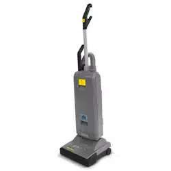
Components
1. Handle grip
2. On/Off switch
3. Handle assembly
4. Retaining ring
5. Cover release
6. Dust bag housing
7. Cover
8. Housing release
9. Brush/suction Head
10. Cable
11. Telescopic handle grip
12. Hose
13. Carrying handle
14. Cable hook
15. Attachment tube
16. Crevice nozzle
17. Upholstery nozzle
18. Foot pedal
19. Exhaust filter cover
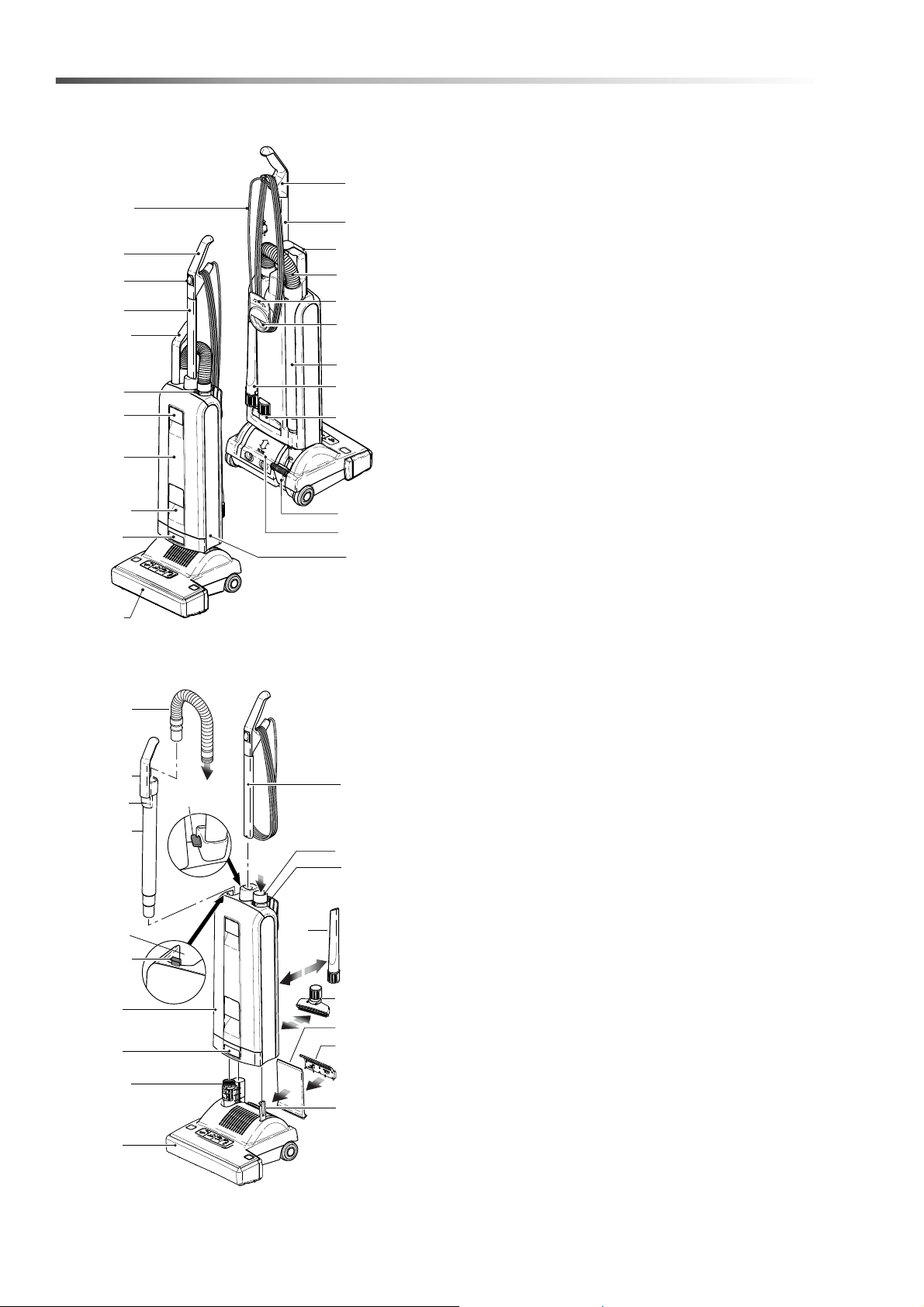
Preparation
Place the brush/suction head on a flat surface with
the neck (20) and the support lever (21) upright Hold
the dust bag housing vertically and place over neck
and support lever. Push firmly down so that the
housing release (8) snaps closed.
Lift the catch (22) then slot the handle assembly into
the top of the dust bag housing (6) and push firmly
down.
When the handle has been pushed down as far as it
will go press catch (22) down. If the handle Is not
pushed fully down the machine will not work.
Insert attachment tube (15) into the channel at the
back of the machine. Locate the handle grip (11) on
the holder (24).
Push the black end of the hose into the connecting
tube (26) so that it clicks into place.
Insert crevice nozzle(16) and upholstery nozzle(17)
into the recesses in the back of the machine.
The device is ready, you can switch on by pressing
the switch (2)
6
1
10
2
3
11
13
7
8
9
5
4
1
11
12
15
16
17
18
13
14
3
19
Picture 1 / Figura 1 / Foto 1
3
26
16
4
22
20
9
6
8
22
15
11
12
17
101
19
21
24
Picture 2 / Figura 2 / Foto 2
27
8.643-387.0 Manual - Karcher Sensor XP15
Loading ...
Loading ...
Loading ...