Place
Model/Serial #
Label Here
Located in Manual Bag
U334-0771X02(00)
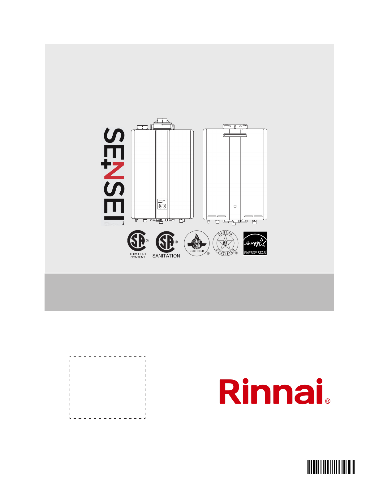
INTERNAL INDOOR MODELS:
RUi REUNFFUS
RUi REUNFFUS
RUi REUNFFUS
RUi REUNFFUS
EXTERNAL OUTDOOR MODELS:
RUe REUNWUS
RUe REUNWUS
RUe REUNWUS
RUe REUNWUS
Tankless Water Heater (Residential)
Installation and Operation Manual
ANSI Z21.10.3 ● CSA 4.3
06000012336368
Rinnai Tankless Water Heater Installation and Operation Manual 2
WARNING
If the information in these instructions is not followed exactly, a re or explosion may result
causing property damage, personal injury, or death.
•
other appliance.
• WHAT TO DO IF YOU SMELL GAS
–
–
– -
tions.
–
•
or the gas supplier.
Assurez-vous de bien suivre les instructions données dans cette notice pour réduire au
minimum le risque d’incendie ou d’explosion ou pour éviter tout dommage matériel, toute
blessure ou la mort.
• -
ité de cet appareil ou de tout autre appareil.
• QUE FAIRE SI VOUS SENTEZ UNE ODEUR DE GAZ :
–
– -
–
–
• -
AVERTISSEMENT
Full-length French and Spanish versions available online at rinnai.us

Rinnai Tankless Water Heater Installation and Operation Manual 3
Contents
1. Welcome ..........................................................................................................................................5
2. Safety ............................................................................................................................................... 6
....................................................................................................................... 7
.................................................................................................................. 7
3. About the Water Heater .................................................................................................................. 9
............................................................................................................................... 9
.......................................................................................................................... 10
......................................................................................................................... 11
........................................................................................................................ 12
........................................................................................................................... 13
3.6 Accessories .......................................................................................................................... 15
4. Install the Water Heater ................................................................................................................ 17
4.1 Installation Guidelines .......................................................................................................... 17
4.2 What You Will Need .............................................................................................................. 18
4.3 Choose an Installation Location ............................................................................................ 19
4.4 Mount the Water Heater to the Wall ...................................................................................... 24
4.5 Vent the Water Heater .......................................................................................................... 26
.......................................................................................................... 50
.................................................................................................... 51
................................................................................................. 52
4.9 Connect Condensate Drain .................................................................................................. 54
....................................................................................................... 57
................................................................................................... 60
............................................................................................. 61
............................................................................................. 63
4.14 Post-Water Heater Installation Checklist ............................................................................. 64
5. Operation ....................................................................................................................................... 66
................................................................................................................ 66
5.2 Operating Instructions ........................................................................................................... 68
5.3 Control Panel ........................................................................................................................69

Rinnai Tankless Water Heater Installation and Operation Manual 4
.......................................................................................................70
................................................................................................................. 71
5.6 Diagnostic Codes .................................................................................................................. 73
6. Maintenance .................................................................................................................................. 76
6.1 Maintenance ......................................................................................................................... 76
.................................................... 78
............................................................................................... 80
6.4 Draining the Water Heater .................................................................................................... 81
7. Appendices ................................................................................................................................... 82
7.1 Massachusetts State Gas Regulations ................................................................................. 82
..................................................................................................................... 84
.................................................................................................................... 85
................................................................................ 86
............................................................... 87
8. Warranty ........................................................................................................................................ 88
Rinnai Tankless Water Heater Installation and Operation Manual 5
ANSI
Institute
BTU
DHW
GPM
LP
NG Natural Gas
PP
PRV
PSI
W.C.
To The Consumer
• -
•
•
-
tions.
•
•
Acronyms and Abbreviations
To The Installer
•
-
•
– Gas sizing
–
–
and local codes
–
–
heaters. Training on Rinnai Tankless
Water Heaters is accessible at
•
-
•
•
1. 1. WelcomeWelcome
Table 1

WARNING AVERTISSEMENT
Rinnai Tankless Water Heater Installation and Operation Manual 6
• -
tions données dans cette notice pour
-
• -
tions données dans cette notice pour
-
•
-
autre appareil.
• QUE FAIRE SI VOUS SENTEZ UNE
ODEUR DE GAZ :
–
–
– -
– -
•
de gaz.
• -
-
•
• -
• WHAT TO DO IF YOU SMELL GAS:
–
–
–
–
•
•
2. 2. SafetySafety
WARNING
WARNING
CAUTION
Rinnai Tankless Water Heater Installation and Operation Manual 7
2.2 Safety Precautions
-
• -
• Keep the area around the appliance clear
• -
• -
• -
–
– -
–
building.
and others.
DANGER
2.1 Safety Symbols

Rinnai Tankless Water Heater Installation and Operation Manual 8
•
-
•
•
heater can be hot to touch.
• -
(Ne pas entreposer ni utiliser d’essence ou
ni d’autres vapeurs ou liquides inamma-
bles à proximité de cet appareil ou de tout
autre appareil.)
• -
tional codes.
•
•
•
•
-
–
•
(N’utilisez pas cet appareil s’il a été plunge
dans l’eau, même partiellement. Faites
inspecter l’appareil par un licence pro-
fessionnelle et remplacez toute partie du
système de contrôle et toute commande
qui ont été plongés dans l’eau.)
•
• -
(En cas de surchaue ou si l’alimentation
en gaz ne s’arrête pas, fermez manuelle-
ment le robinet d’arrêt de l’admission de
gaz.)
•
•
• -
•
• -
gas appliance.
Rinnai Tankless Water Heater Installation and Operation Manual 9
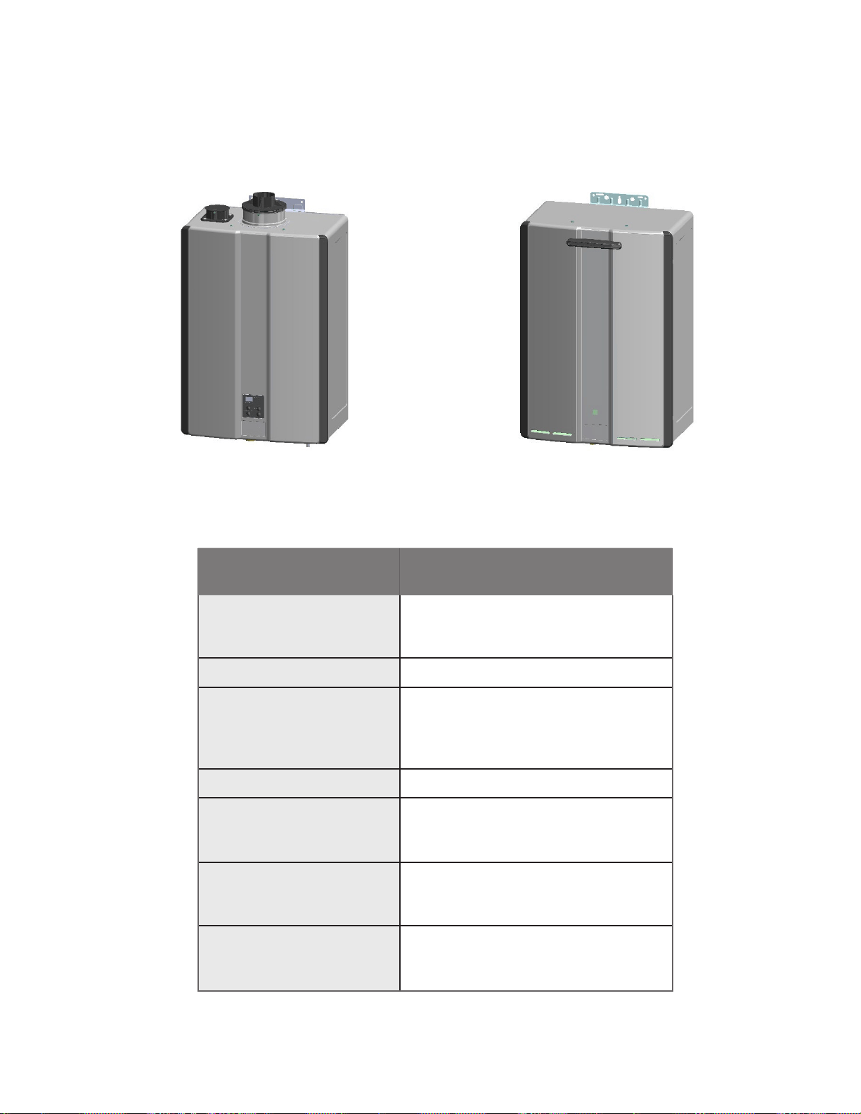
3. 3. About the Water HeaterAbout the Water Heater
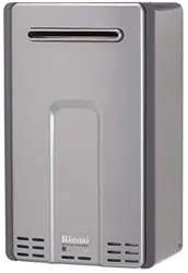
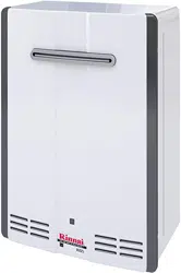
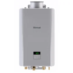
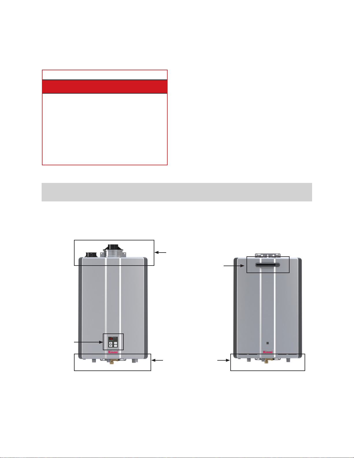
3.1 Front View
Indoor Outdoor
Figure 1: Front view
Topics in this section
•
•
•
•
•
• Accessories
Controller
Piping Connections
Vent
Connections
Duct
Rinnai Tankless Water Heater Installation and Operation Manual 10
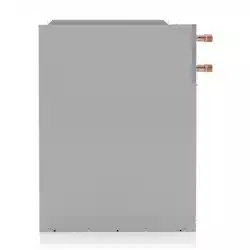
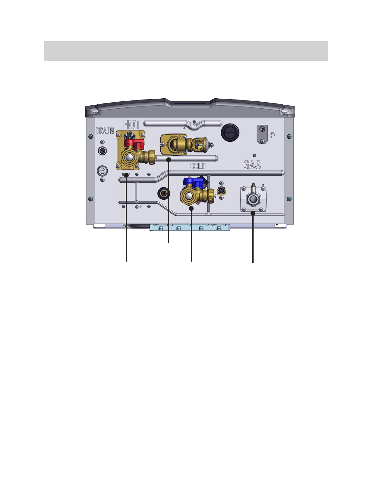
3.2 Bottom View
Gas Inlet
Hot Water
Outlet
Cold Water
Inlet
Figure 2: Bottom view
Rinnai Tankless Water Heater Installation and Operation Manual 11
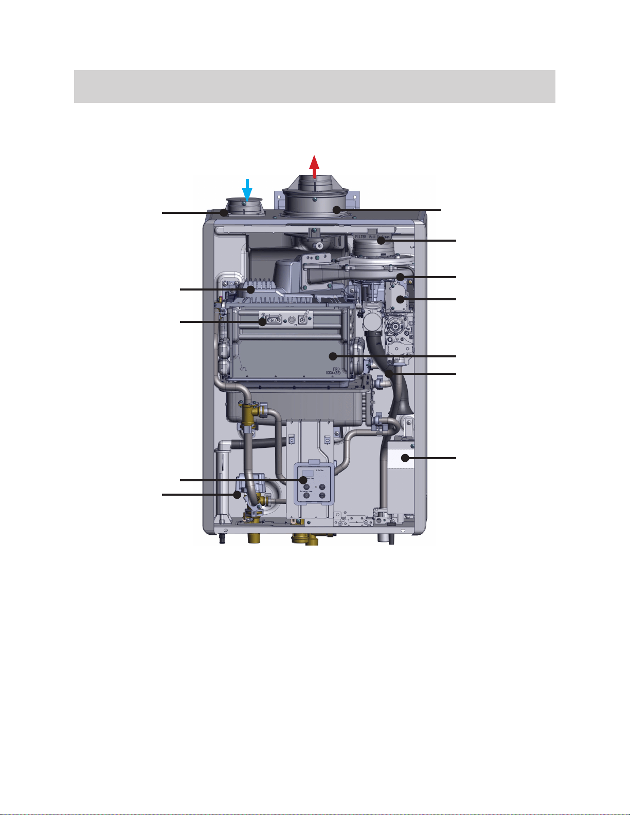
3.3 Components
Air Intake
Ignition Unit
Control Panel
Air Inlet Filter
Venturi
Silencer
Intake
Figure 3: Components
Rinnai Tankless Water Heater Installation and Operation Manual 12
3.4 Specifications
Indoor Units Outdoor Units
RU199i RU180i RU160i RU130i RU199e RU180e RU160e RU130e
Minimum Gas
Consumption
Btu/h
Maximum Gas
Consumption
Btu/h
Flow Rate
1
(Min-Max)
0.26-9.8 GPM
0.26-9.0 GPM
0.26-8.0 GPM
0.26-6.6 GPM
0.26-9.8 GPM
0.26-9.0 GPM
0.26-8.0 GPM
0.26-6.6 GPM
Max Flow Rate
with Parameter
Adjustment
11 GPM
10 GPM
9 GPM
7 GPM
11 GPM
10 GPM
9 GPM
7 GPM
Weight 64 lb (29 kg) 62 lb (28 kg) 64 lb (29 kg) 62 lb (28 kg)
Sound Level 48 dB 47 dB 53 dB 52 dB
Electrical Data
Normal 84 W 65 W 52 W 38 W 81 W 62 W 49 W 36 W
Standby
1.3 W
With Freeze
Protection
148 W 152 W
Max Current
Fuse
Temperature
Setting
Bypass Flow
Control
Electronic
Gas Supply
Pressure
2
Natural Gas
Propane
Type of Appliance
Ignition System Direct Electronic Ignition
Electric
Connections
Water Supply
Pressure
Remote Control
Cable
ENERGY STAR®
Qualied
Yes
Complies with
South Coast
Air Quality
Management
District 14 ng/J
or 20 ppm NOx
emission levels
Yes
1
2
Rinnai Tankless Water Heater Installation and Operation Manual 13
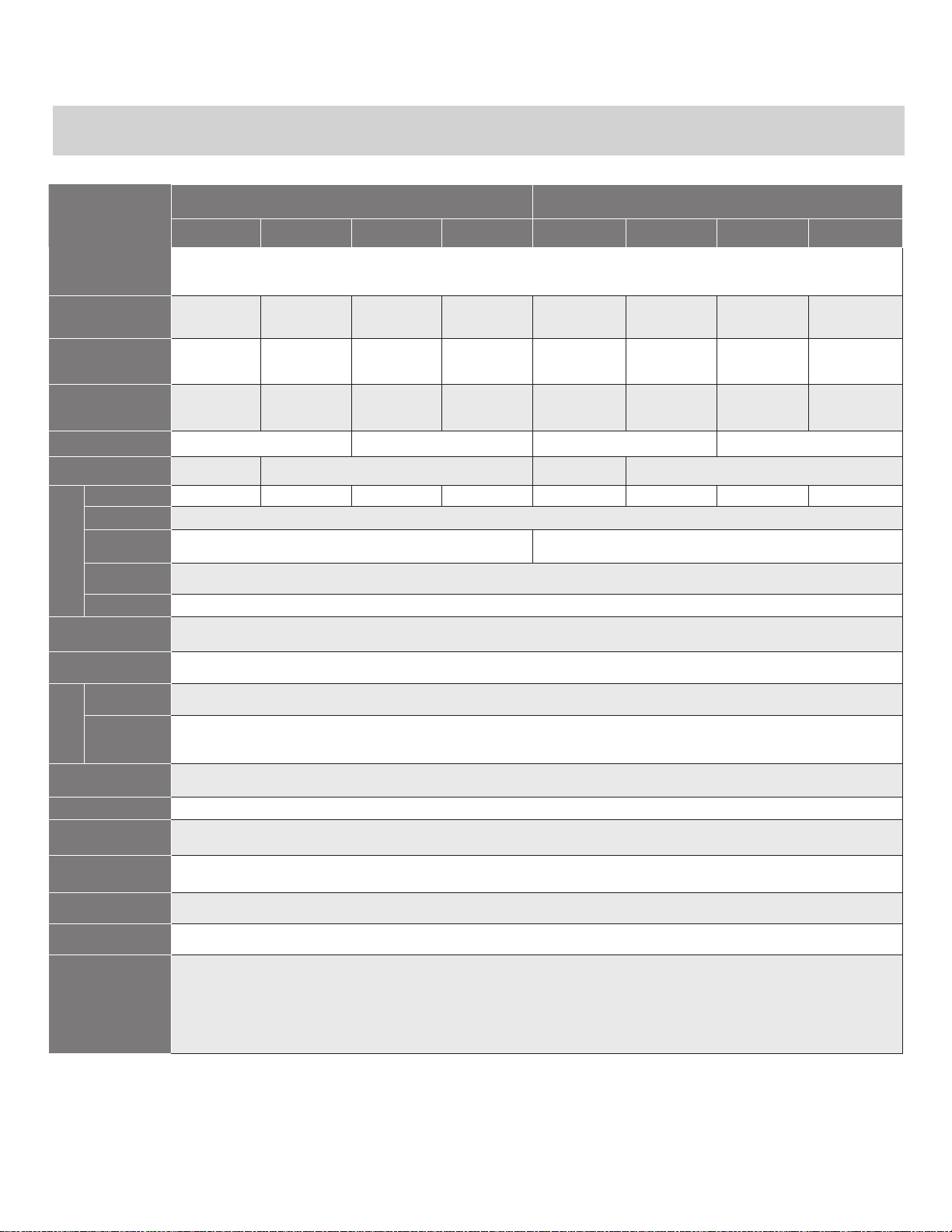
3.5 Dimensions
Indoor Models
Outdoor Models
Vent Connection:
3 in./5 in. Concentric.
Figure 4: Indoor Dimensions
Figure 5: Outdoor Dimensions
Rinnai Tankless Water Heater Installation and Operation Manual 14
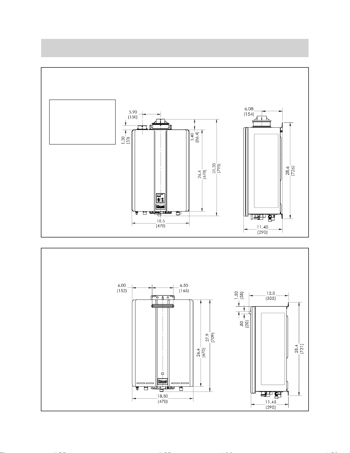
5.6. (142)
5.10 (129)
7.75 (197)
5.25 (133)
3.5 (89)
2.8 (71)
7.6 (193)
6.2 (157)
1.22 (31)
.36 (9)
Cold Inlet
Gas
Hot Outlet
Condensate
Drain
Pressure
Connection Connection Size
Gas 3/4 in. NPT
Cold Inlet 3/4 in. NPT
Hot Outlet 3/4 in. NPT
Condensate Drain 1/2 in. NPT
M33 Thread
3.5.1 Supply Connections
Figure 6: Supply Connections
Rinnai Tankless Water Heater Installation and Operation Manual 15
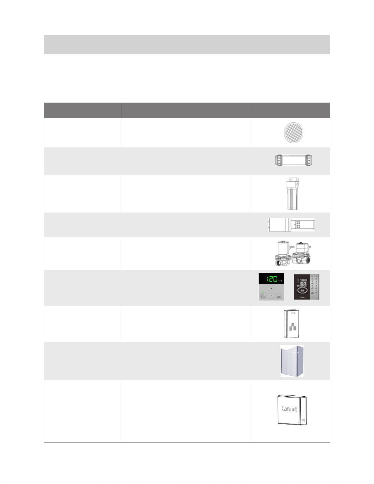
Product Product Description Image
Part #: 108000105
Condensate Neutralizer
Part #: 804000074
ScaleCutter
Part #: 103000038
Cartridge
Part #: 103000039
Part #: 104000059
-
Additional Controller
Part #: MC-601-BK
MC-601-W
MC-195T-US
Part #: RGB-CTWH-4
Part #: PCD07-SM
Control-R™ Wi-Fi
Module (And
Accessories)
Part #: RWM101
-
-
The Control-R™ Wi-Fi Module and MC-
together.
3.6 Accessories
Table 4: Accessories
Rinnai Tankless Water Heater Installation and Operation Manual 16
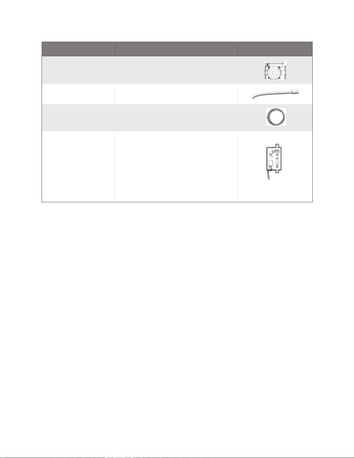
Product Product Description Image
Part #: RWMGTK03
Part #: 105000250
-
EZConnect™ Cable
Part #: REU-EZC-2
Part #: REU-OPU3
-
handler applications.

Rinnai Tankless Water Heater Installation and Operation Manual 17
4. 4. Install the Water HeaterInstall the Water Heater
THIS SECTION IS INTENDED FOR THE
INSTALLER
Heaters is accessible online at
4.1 Installation
Guidelines
guidelines:
•
-
• -
•
-
•
•
•
•
-
-
• -
(En cas de surchaue ou si l’alimentation
en gaz ne s’arrête pas, fermez manuelle-
ment le robinet d’arrêt de l’admission de
gaz.)
•
-
-
ance.
Topics in this section
• Installation Guidelines
•
• Choose Installation Location
• Mount Water Heater to the Wall
• Vent Water Heater
•
•
•
• Connect Condensate Drain
•
•
•
•
• Post-Installation Checklist

Rinnai Tankless Water Heater Installation and Operation Manual 18
DO NOT
•
•
•
-
-
•
•
•
spas) in the appliance.
• DO NOT use substitute parts that are not
4.2 What You Will
Need
4.2.1 Items Included
Unpack the Rinnai Tankless Water Heater
Care at 1-800-621-9419.
• Rinnai Tankless Water Heater
•
•
•
-
nance)
• Literature Bag
– Tankless Water Heater Installation and
–
–
printed QR code)
•
connection)
•
•
4.2.2 Items Needed (Field-
Supplied)
•
•
• Wire Cutters
•
•
•
• Soap or gas leak detector solution
•
•
• Pipe insulation
•
•
•
•
• Torch set
• Copper tubing cutter
• Steel pipe cutter
• Heat tape
•
•
•
•
•

Rinnai Tankless Water Heater Installation and Operation Manual 19
4.3 Choose an
Installation
Location
4.3.1 Water Quality
Guidelines
SS
SS
4.3.2 Environment
Regulation
Contaminant Maximum Level
Total Hardness
Chlorides *
Copper *
Iron *
Manganese *
pH * 6.5 to 8.5
Solids) *
Zinc *

Rinnai Tankless Water Heater Installation and Operation Manual 20
4.3.3 Internal (Indoor) Water
Heaters
•
-
-
•
be installed so that it is sheltered/protected
•
-
•
-
•
-
-
4.3.4 External Water Heaters
and Vent Terminations
•
•
be installed so that it is sheltered/protected
•
•
-
-
Rinnai Tankless Water Heater Installation and Operation Manual 21
4.3.5 Freeze Protection
drained).
Figure 7: Freeze Protection Piping Diagram
Route Drain Per Local Code
Cold Water
Supply Line
1/2 in. Normally Open Solenoid Valve
Hot Water
Supply Line
3/4 in. Normally Closed Solenoid Valve
Legend
Vacuum Breaker
Pressure Relief Valve
Union
Check Valve
Ball Valve
Solenoid Valve
Drain Valve
* Position vacuum breaker
above water heater.
Gas Supply
Freeze Protection Piping Diagram
Vacuum Breaker *
Union
Route Drain Per Local Code
Hot Water
Line
Rinnai Tankless Water Heater Installation and Operation Manual 22
4.3.6 Clearances
Location
Top
0 in. from vent components
Front 0 in.
Clearance for servicing is 24 in. (610 mm)
in front of water heater
Back 0 in.
Add 0.25 in. (6.35 mm) for recess box
Vent
(Internal/Indoor Models)
0 in.
(External/Outdoor Models)
Side
Top Top
Side
BottomBottom
FrontFront
Figure 8: Clearances
Table 6: Clearances

Rinnai Tankless Water Heater Installation and Operation Manual 23
4.3.7 Installation Location Checklist
National Fuel Gas Code, ANSI Z221.3/NFPA 54Natural Gas and Propane
Installation Code, CSA B149.1
Rinnai Tankless Water Heater Installation and Operation Manual 24
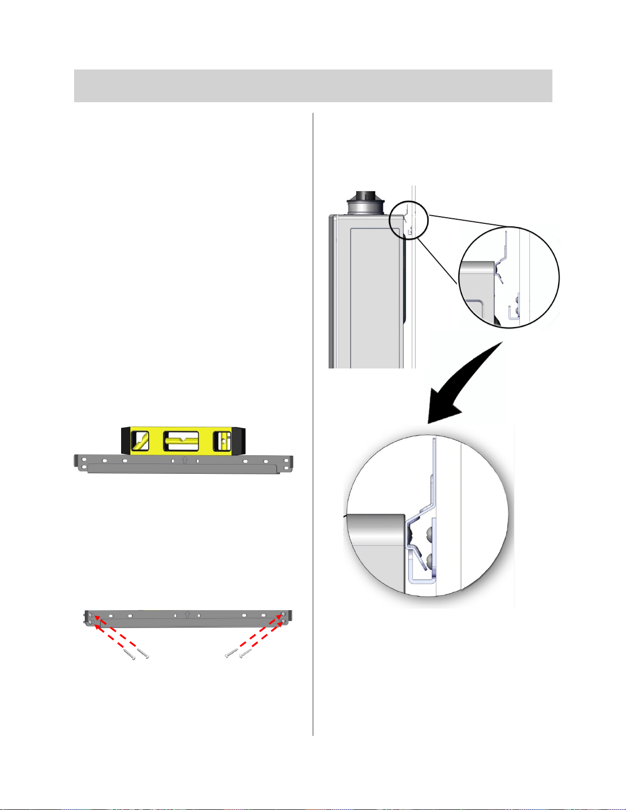
3.
4.4 Mount the Water Heater to the Wall
4.4.1 Mount the Internal
(Indoor) Water Heater
You Will Need:
• Rinnai Tankless Water Heater
(Internal/Indoor Model)
• Wall Mounting Bracket
Supplied by Installer:
•
•
Use appropriate screws for type of wall
constructions.
Instructions:
1.
2.
Figure 10: Secure the bracket
Figure 11: Mount top bracket
Figure 9: Level the bracket
Rinnai Tankless Water Heater Installation and Operation Manual 25
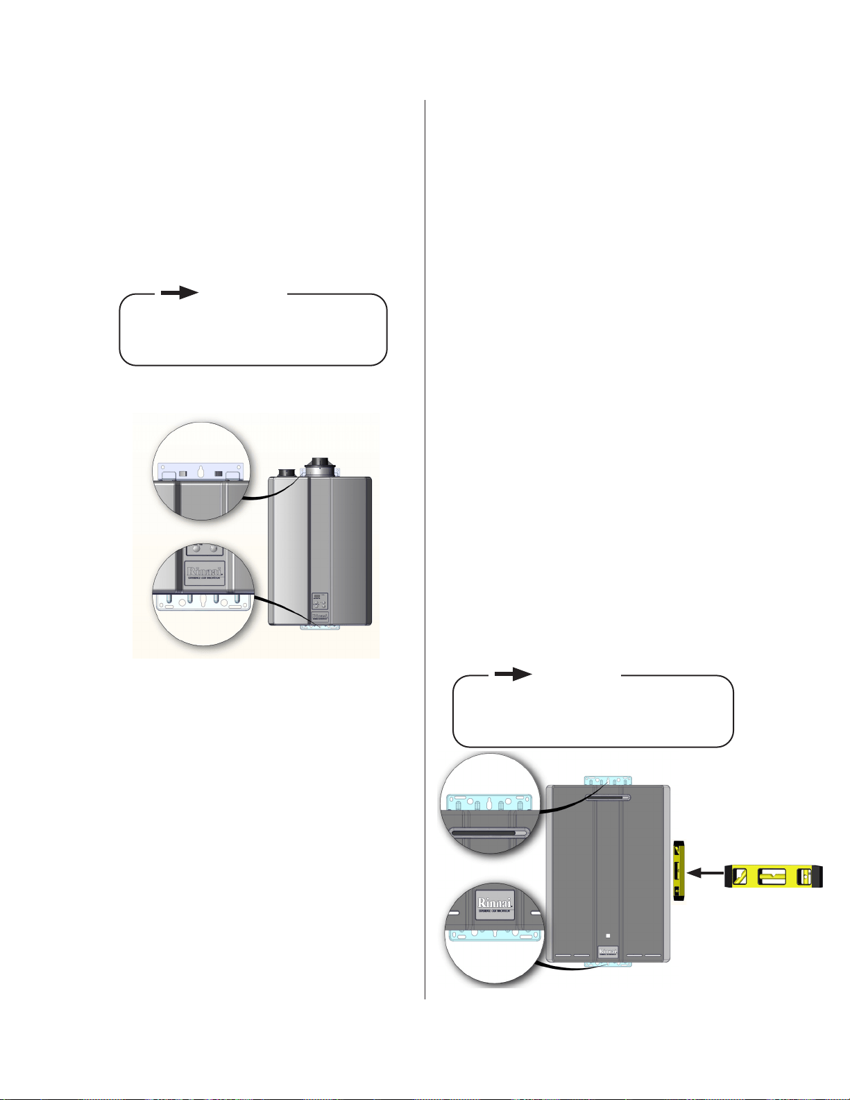
4.
•
brackets.
• -
Top Bracket
Bracket
4.4.2 Mount the External
(Outdoor) Water Heater
to the Wall
You Will Need:
• Rinnai Tankless Water Heater
(External/Outdoor Model)
Supplied by Installer:
•
• -
lation
Use appropriate screws for type of wall
construction.
Instructions:
1.
•
brackets.
• -
• -
Figure 12: Mount bottom bracket
Figure 13: Mount water heater
IMPORTANT
IMPORTANT
Rinnai Tankless Water Heater Installation and Operation Manual 26
4.5 Vent the Water Heater
4.5.1 Guidelines
•
•
-
-
ucts.
•
codes.
•
(Non-Direct Vent).
•
NFPA 54.
•
-
•
• Venting should be as direct as possible
• -
instructions.
•
•
•
instructions.
•
-
tor.
•
• DO NOT use cellular core PVC/CPVC.
•
•
•
•
•
•
or appliance.
• -
WARNING
Rinnai Tankless Water Heater Installation and Operation Manual 27
4.5.2 Venting Installation
Sequence
1.
2.
3.
4.
installation instructions.
5.
6.
7.
8.
•
•
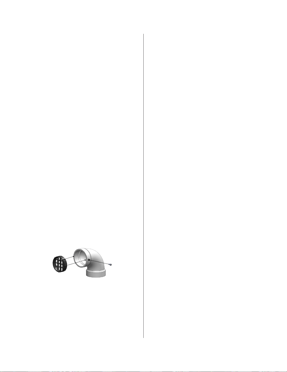
4.5.3 Termination
Considerations
•
• -
•
inlets.
•
•
•
could create a nuisance or hazard or
•
porch):
•
•
•
-
-
tion.
Figure 14: Vent screen
Rinnai Tankless Water Heater Installation and Operation Manual 28
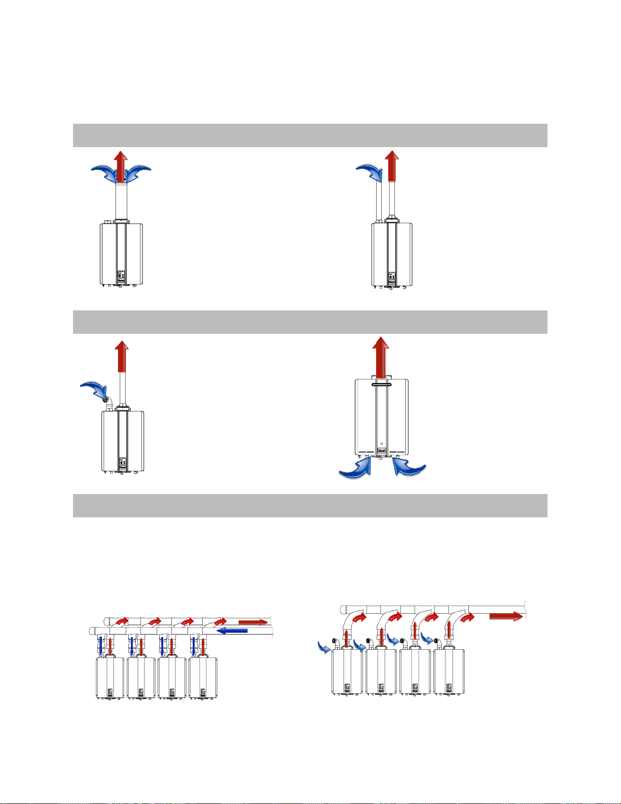
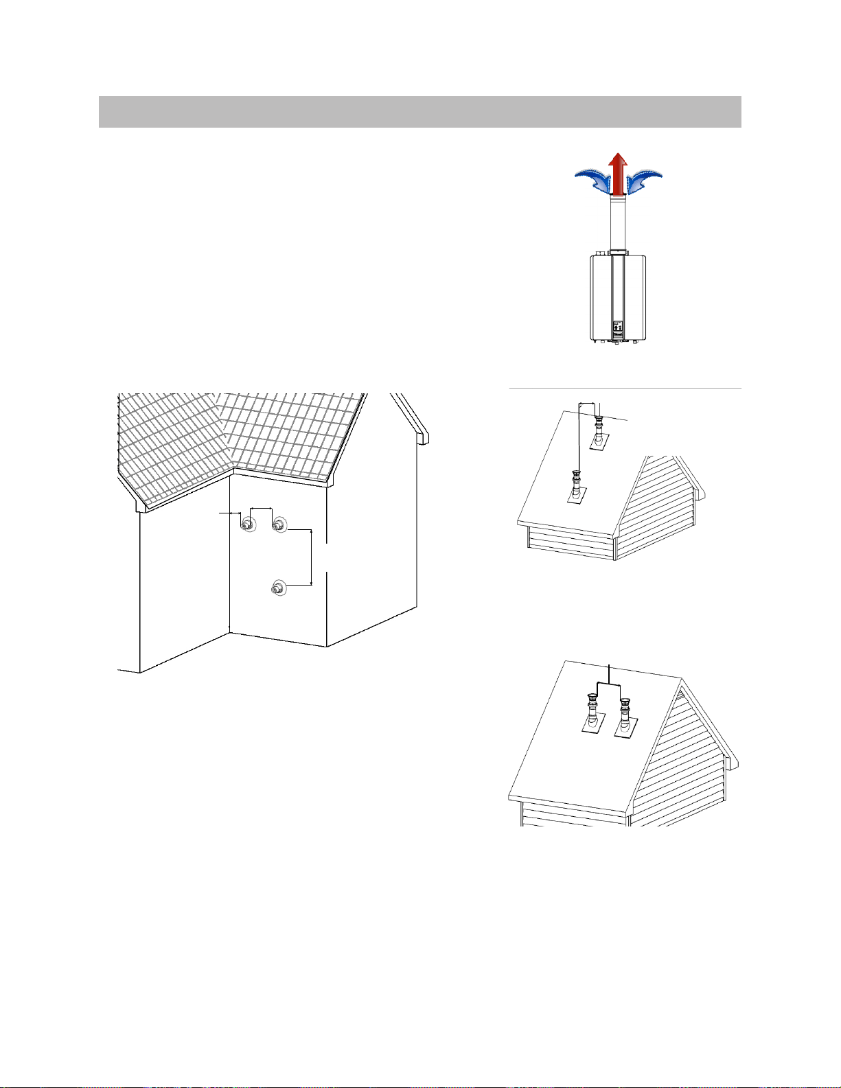
4.5.4 Venting Options
1. Direct Vent (Concentric Pipe and Twin Pipe)
2. Non-Direct Vent (Room Air and External)
3. Common Vent (Indoor Unit Only. Direct Vent and Non/Direct/Room Air Vent)
Concentric Pipe
concentric connection. Hot
through separate
penetrations.
outside.
heater.
Direct Vent
the outside.
Figure 15: Concentric Pipe
Figure 16: Twin Pipe
Figure 17: Room Air
Figure 18: External
Figure 19: Common Vent, Direct Vent
Figure 20: Common Vent, Room Air
Rinnai Tankless Water Heater Installation and Operation Manual 29
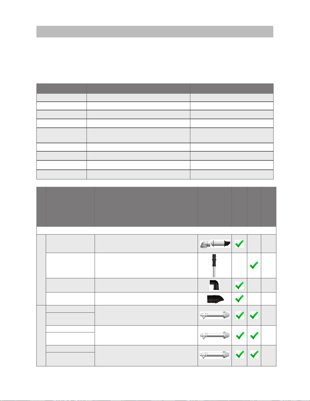
1. Direct Vent (Concentric Pipe and Twin Pipe)
Manufacturer Phone Web Site
Ubbink 800-621-9419
877-434-3432
Heat-Fab 800-772-0739
Metal Fab 800-835-2830
IPEX U.S.: 800-463-9572
Canada: 866-473-9462
DuraVent 800-835-4429
800-232-5690
877-955-4805
800-995-2222
Manufacturer
Manufacturer
Part number
Product
Description
Diagram
Horizontal
Vertical
Equivalent
Length (ft)
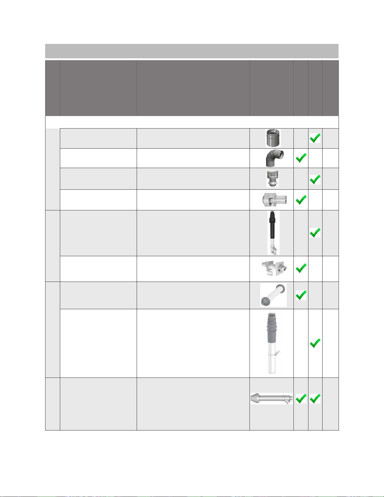
2 in. /4 in. CONCENTRIC VENT TERMINATIONS
UBBINK
US/ Canada
229031/ 229012NPP
229032/ 229013NPP
5
224359/224356NPP
5
710202NPP
(Use
with Wall Terminal)
5
710215NPP
(Use
with Wall Terminal)
5
IPEX
FGV Concentric Vent Kit (16 in. length) 20
1906005PVC
FGV Concentric Vent Kit (16 in. length) 20
196105PVC
196125
FGV Concentric Vent Kit (40 in. length) 20
196125PVC
Rinnai Tankless Water Heater Installation and Operation Manual 30
1. Direct Vent (Concentric Pipe and Twin Pipe)
Manufacturer
Manufacturer
Part number
Product
Description
Diagram
Horizontal
Vertical
Equivalent
Length (ft)
2 in. /4 in. CONCENTRIC VENT TERMINATIONS (continued)
ROYAL
52CVKGS6502 20
52CVKGVS6502-28 20
52CVKGVS6502-40 20
CENTROTHERM
ICRT2439 20
DURAVENT
2PPS-VKL/VK-TCL FGV Concentric Vent Kit (16 in. length) 20
2PPS-HKL
Kit-Concentric
20
ECCO
190288
5
190295
5
DIVERSITECH
CVENT-2
20
Rinnai Tankless Water Heater Installation and Operation Manual 31
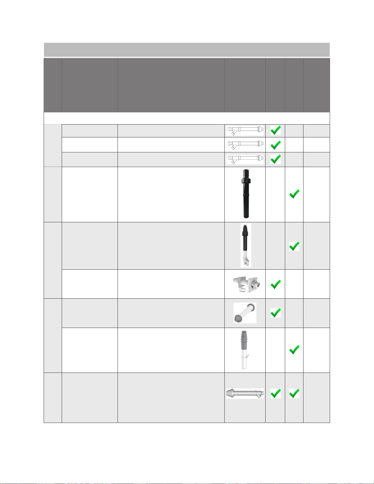
1. Direct Vent (Concentric Pipe and Twin Pipe)
Manufacturer
Manufacturer
Part number
Product
Description
Diagram
Horizontal
Vertical
Equivalent
Length (ft)
3 in. /5 in. CONCENTRIC VENT TERMINATIONS
UBBINK
223176PP
223177PP
5
223186PP
Kit 19 in.
16
224047PP
Kit
24
184162PP
5
IPEX
20
196006PVC
20
196106PVC
20
196116PVC
ROYAL
52CVKGVS6503(PVC)/
52CVKGVSF9003(CPVC)
20
52CVKGVS6503-32(PVC)/
52CVKGVSF9003-32(CPVC)
20
52CVKGVS6503-44(PVC)/
52CVKGVSF9003-44(CPVC)
20
HEAT-FAB
SC03HT
20
SC03VT
20
CENTRO
THERM
ICRT3539
20
Rinnai Tankless Water Heater Installation and Operation Manual 32
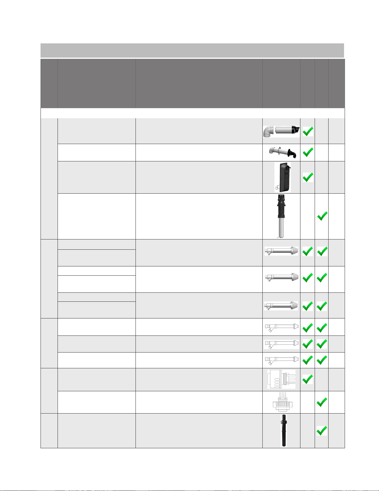
1. Direct Vent (Concentric Pipe and Twin Pipe)
Manufacturer
Manufacturer
Part number
Product
Description
Diagram
Horizontal
Vertical
Equivalent
Length (ft)
3 in. /5 in. CONCENTRIC VENT TERMINATIONS (Continued)
METAL-FAB
3CGRLSV Vertical Adapter 1
3CGRLSH Horizontal Adapter 6
3CGRVT 5
3CGRHT
Concentric
16
DURAVENT
3PPS-VKL/VK-TCL
Concentric
20
3PPS-HKL
Concentric
20
ECCO
190388
5
190395 5
DIVERSITECH
CVENT-3
20
Rinnai Tankless Water Heater Installation and Operation Manual 33
1. Direct Vent (Concentric Pipe and Twin Pipe)
Manufacturer
Manufacturer
Part number
Product
Description
Diagram
Horizontal
Vertical
Equivalent
Length (ft)
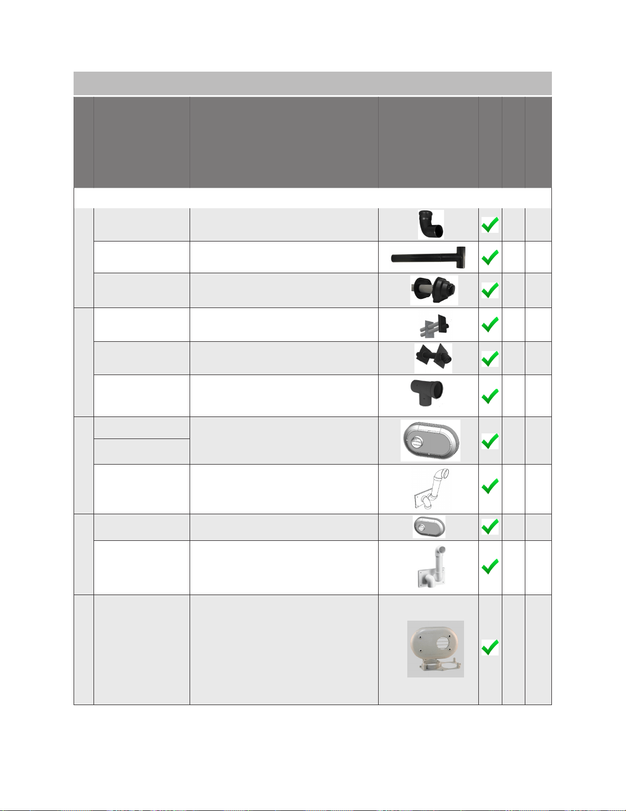
2 in. TWIN PIPE TERMINATIONS
CENTROTHERM
ISELL0287UV 6
ISTT0220 6
ISLPT0202 5
DURAVENT
2PPS-HTPL 10
2PPS-HSTL 6
2PPS-TBL 2 in. Black UV Resistant Tee 5
IPEX
196984
5
196984PVC
081216
16
ROYAL
52SWVKGVS6502 PVC Side Wall Vent Kits 5
52WTVKGVS6502 PVC Wall Vent Kits 16
DIVERSITECH
HVENT-2 5
Rinnai Tankless Water Heater Installation and Operation Manual 34
1. Direct Vent (Concentric Pipe and Twin Pipe)
Manufacturer
Manufacturer
Part number
Product
Description
Diagram
Horizontal
Vertical
Equivalent
Length (ft)
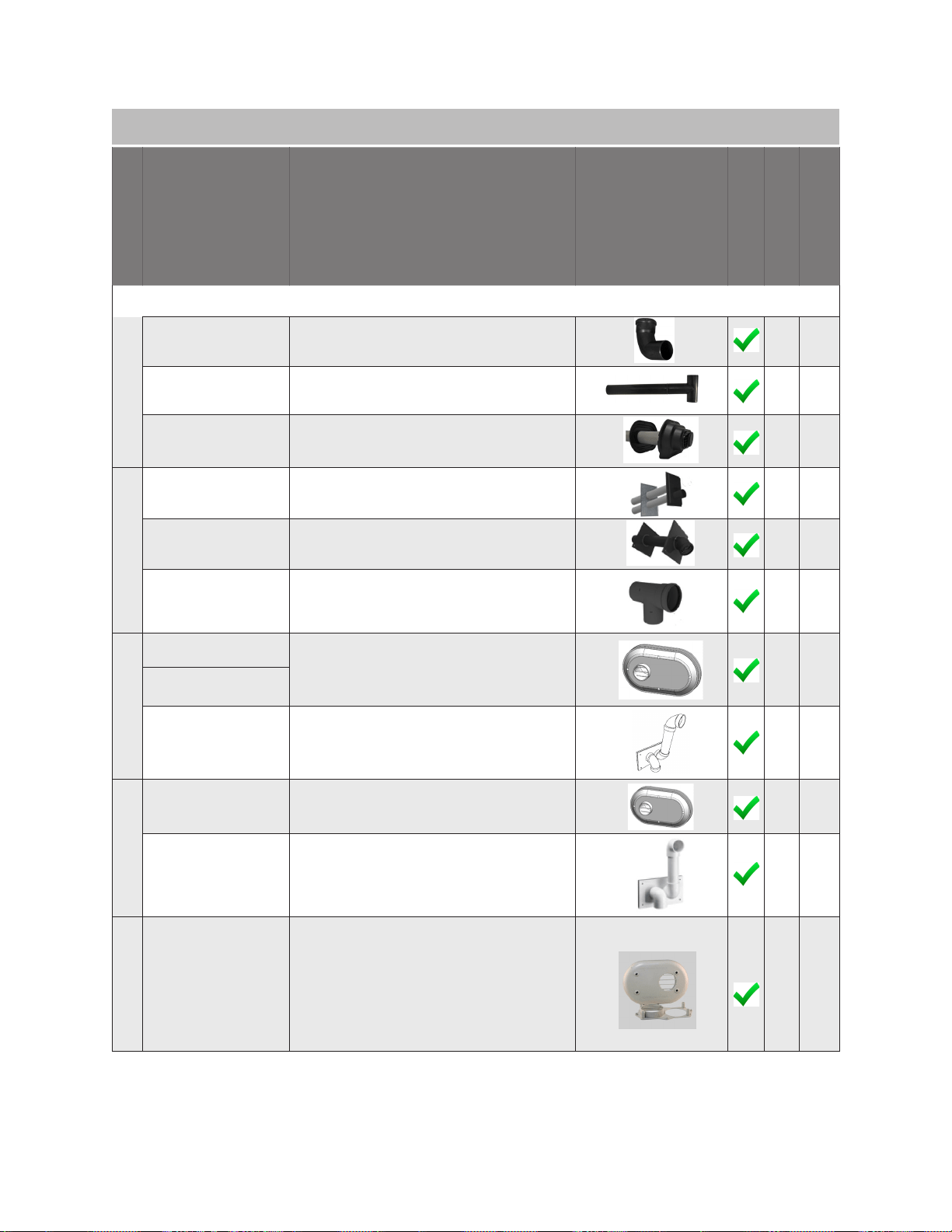
3 in. TWIN PIPE TERMINATIONS
CENTROTHERM
ISELL0387UV 6
ISTT0320 6
ISLPT0303 5
DURAVENT
3PPS-HTPL 10
3PPS-HSTL 5
3PPS-TBL 3 in. Black UV Resistant Tee 6
IPEX
196985
5
196985PVC
081219 16
ROYAL
52SWVKGVS6503 PVC Side Wall Vent Kits 5
52WTVKGVS6503 PVC Wall Vent Kits 16
DIVERSITECH
HVENT-3 5
Rinnai Tankless Water Heater Installation and Operation Manual 35
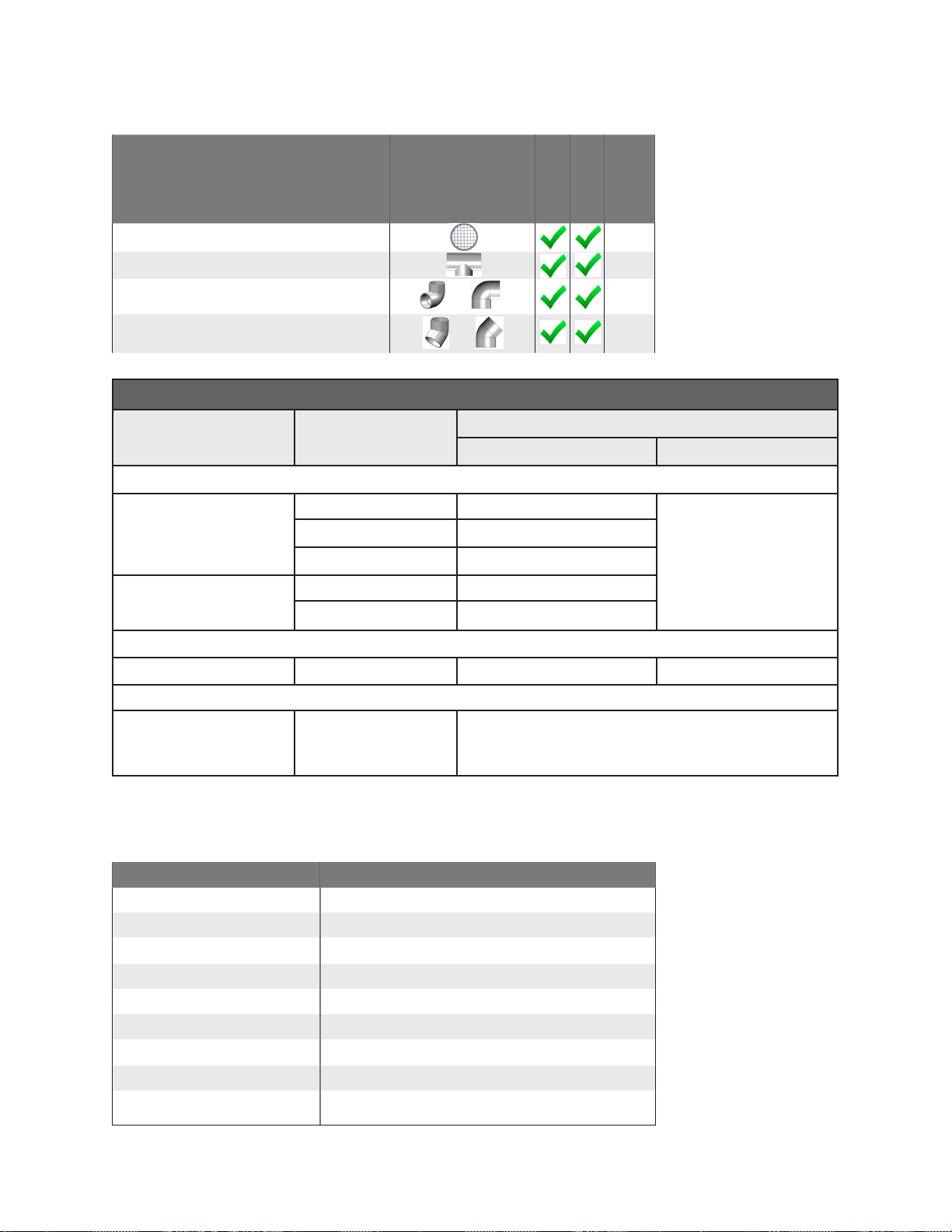
Product
Description
Horizontal
Vertical
Vent Screen N/A
Tee 5
5
2.5
Approved PVC/CPVC Vent and Air Piping Material
Material
United States Canada
Thermoplastic Piping Materials
Intake Pipe and Fittings
PVC Schedule 40 ANSI/ASTM D1785
this table.
PVC-DWV ANSI/ASTM D2665
CPVC Schedule 40 ANSI/ASTM F441
PVC ANSI/ASTM D2564
CPVC Schedule 40 ANSI/ASTM F493
Non-Metallic Vent Material
ABS SCH 40 DWV ASTM-D2661 or CSA B181.1 NOT PERMITTED
PVC Vent Screens
•
•
Vent Material
Ubbink
Heat-Fab Metal
Metal Fab Metal
IPEX PVC/CPVC
DuraVent
PVC
PVC/CPVC
Rinnai Tankless Water Heater Installation and Operation Manual 36
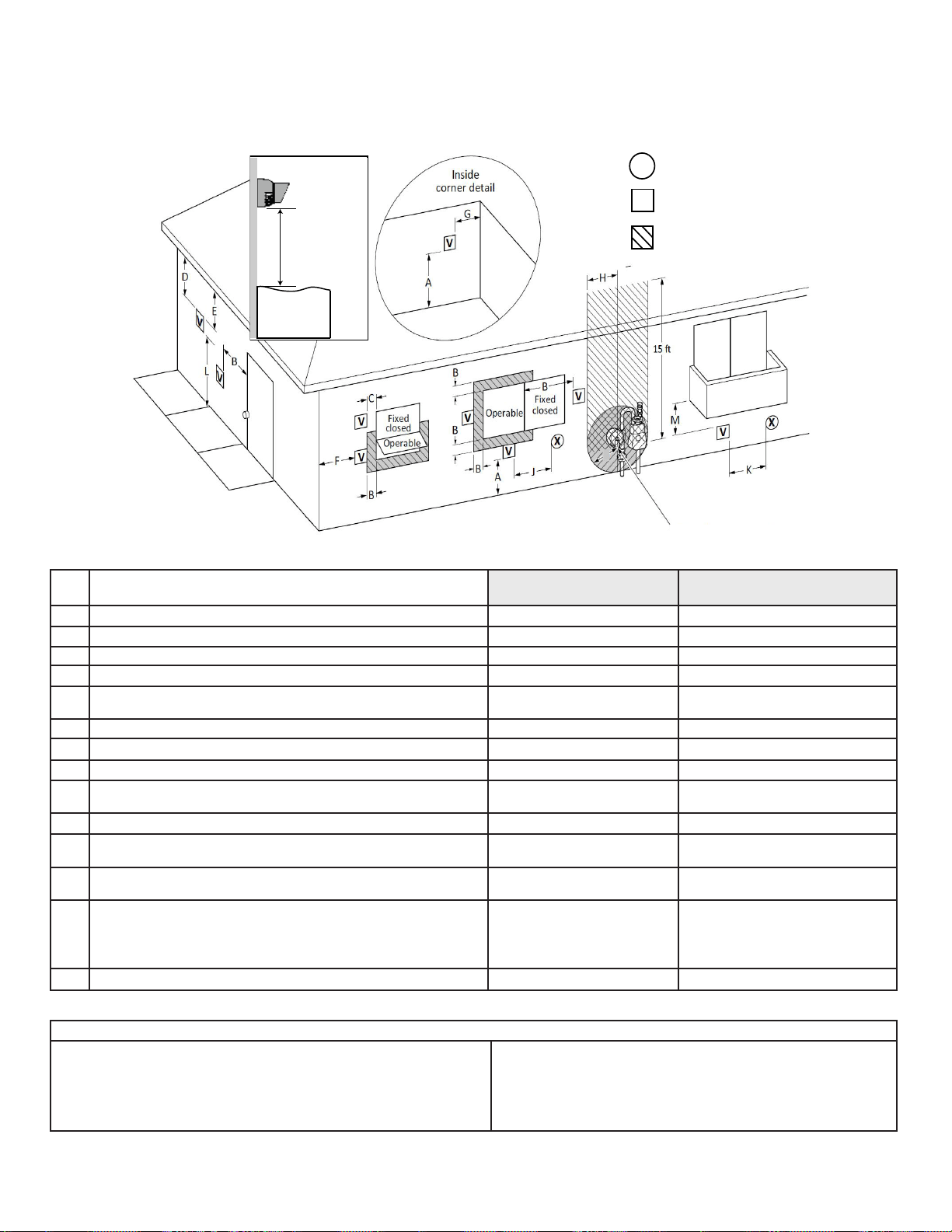
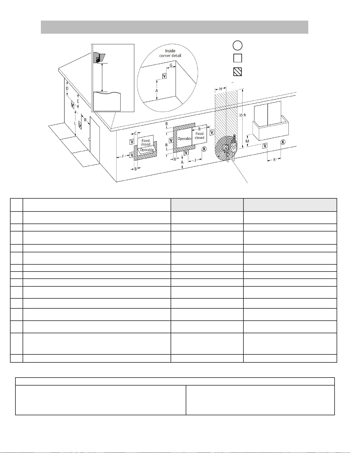
4.5.5 Direct Vent (Concentric and Twin Pipe):
Termination Clearances
Canadian Installations
1
(CSA B149.1)
U.S. Installations
2
(ANSI Z223.1/NFPA 54)
Ref Description Direct Vent (Indoor Unit) Direct Vent (Indoor Unit)
A
B
C * *
D
* *
E * *
F Clearance to outside corner * *
G Clearance to inside corner *
H
12 in.
I *
J
K
L
cause a nuisance or hazard.
M *
Clearance to opposite wall is 24 in. (60 cm).
(Dégagement conforme aux codes
d’installation locaux et aux exigences du foumisseur de gaz.)
AIR SUPPLY INLET
VENT TERMINAL
AREA WHERE TERMINAL
IS NOT PERMITTTED
X
V
SNOW
TERMINATION
Clearance in
A also
applies to
anticipated
AIR SUPPLY INLET
VENT TERMINAL
AREA WHERE TERMINAL
IS NOT PERMITTTED
X
V
SNOW
TERMINATION
Clearance in
A also
applies to
anticipated
Figure 21: Direct Vent Termination Clearances
Table 12
Notes:
1
2
I
Rinnai Tankless Water Heater Installation and Operation Manual 37
1. Direct Vent (Concentric Pipe)
through a single concentric connection.
air
air
Figure 22: Concentric Pipe Termination Clearances
Insi de
Co r ne r
12 in.
(0.30 m)
12 in.
(0.30 m)
60 in. (1.52 m) ver�cally
betwe en terminal s
60 in. (1.52 m)
Note: 24 in. (0.61 m)
to wall or parapet
12 in. (0.30 m)
Figure 24: Between terminals at
dierent levels
Figure 25: Between terminals at same
level
Corner
Figure 23: Concentric Pipe
Rinnai Tankless Water Heater Installation and Operation Manual 38
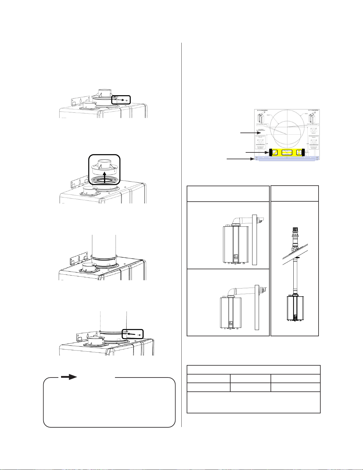
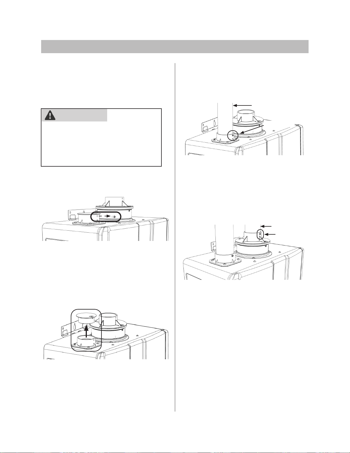
Concentric Pipe: Installation
Instructions
1.
2.
3.
seated.
4.
Concentric
Vent
Mount Concentric Pipe Through Wall
Wall Mounting
Wall Mounting
Bracket
Table 13: Concentric Pipe: Vent Applications
and
Vent Sizes
Vent Lengths
•
•
Figure 29
Figure 26
Figure 27
Figure 28
Figure 30
codes.
IMPORTANT
Rinnai Tankless Water Heater Installation and Operation Manual 39
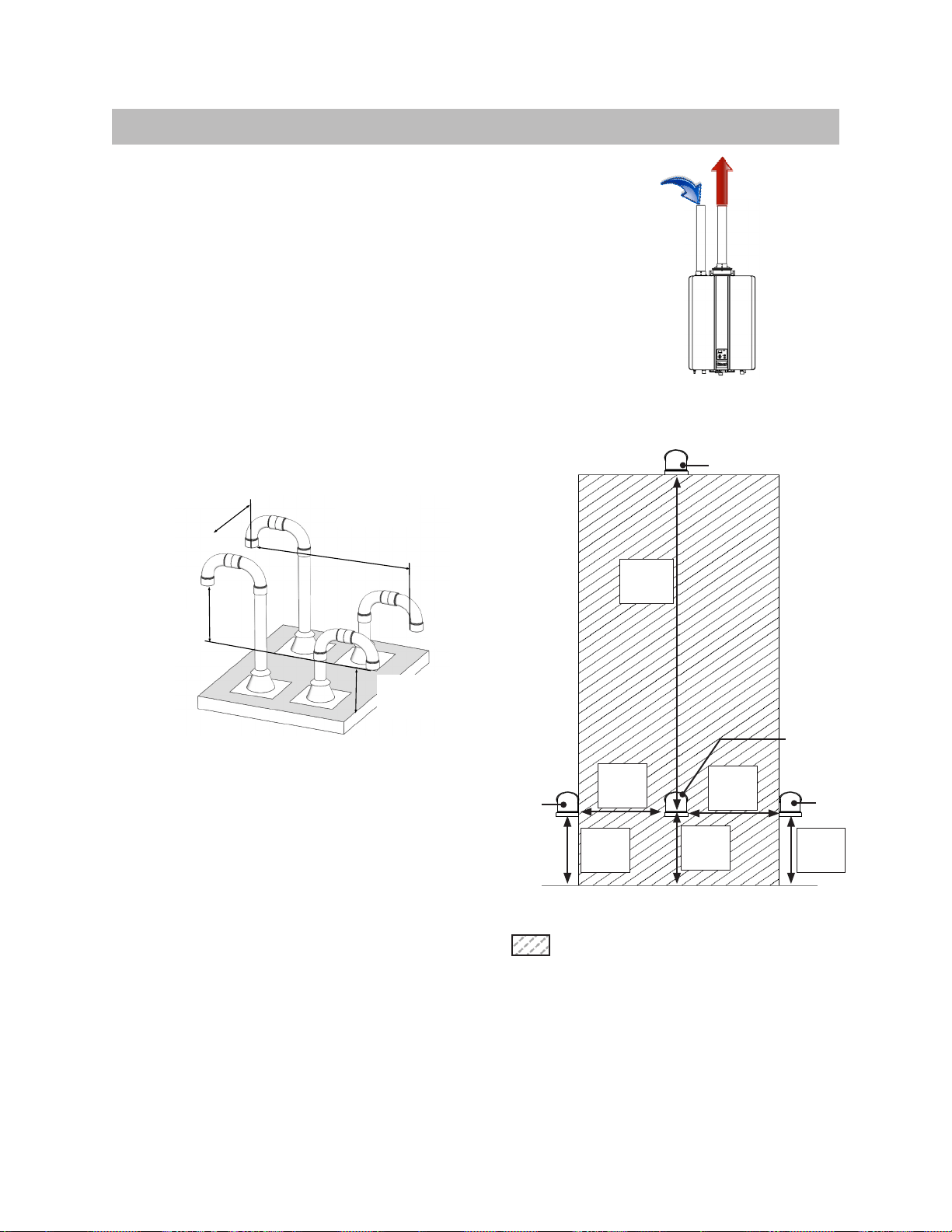
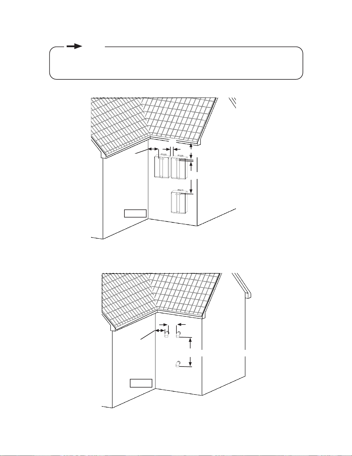
1. Direct Vent (Twin Pipe)
opening
Air
grade or anticipated
Roof
Figure 32: Twin Pipe Vertical
Termination of Multiple Water Heaters
Intake
60 in.
12 in.
12 in.
12 in.
12 in.
12 in.
IntakeIntake
Figure 33: Horizontal Vent and Combustion
Air Piping
Figure 31
Rinnai Tankless Water Heater Installation and Operation Manual 40
1. Direct Vent (Twin Pipe)
Twin Pipe Installation Instructions
1.
2.
cap.
3.
4.
Figure 34
Figure 35
Figure 36
Figure 37
WARNING
Rinnai Tankless Water Heater Installation and Operation Manual 41
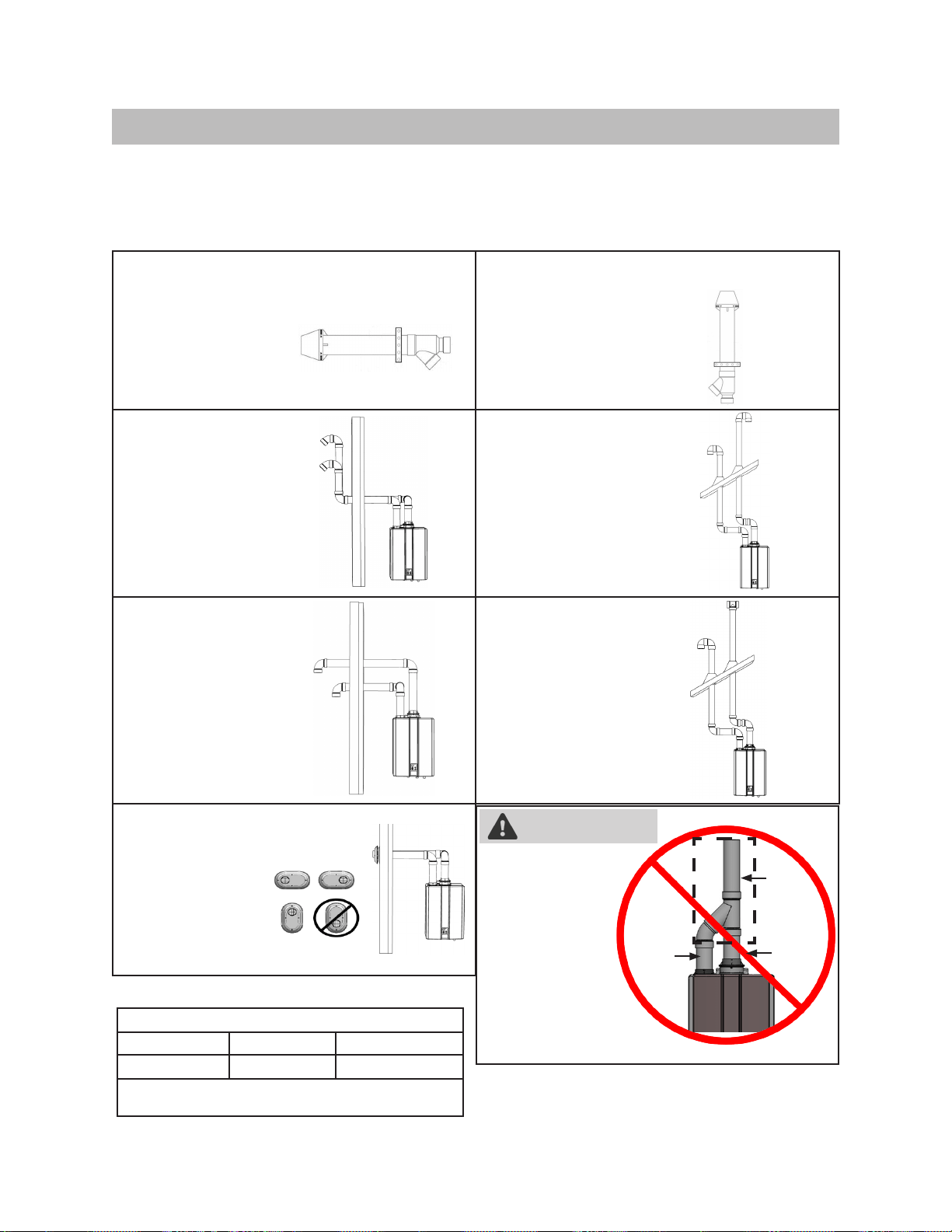
This conguration requires the use of a Concentric Vent
Termination
2 in. or 3 in. PVC/
Concentric Side Wall
This conguration requires the use of a Concentric Vent
Termination
2 in. or 3 in. PVC/CPVC
2 in. or 3 in. Schedule
40 PVC/CPVC or ABS Snorkel
2 in. or 3 in. Schedule 40
PVC/CPVC or ABS Standard
2 in. or 3 in. Schedule
or Tee Side Wall
2 in. or 3 in. Schedule
40 PVC/CPVC or ABS Tee
2 in. or 3 in. PVC
MUST NOT be
brought together
into a single
PVC pipe using
1. Direct Vent (Twin Pipe)
Twin Pipe Example Vent Applications
Single
Pipe
Air
Vent Sizes
Vent Lengths
•
•
WARNING
Rinnai Tankless Water Heater Installation and Operation Manual 42
2. Non-Direct Vent (Room Air and External)
Canadian Installations
1
(CSA B149.1)
U.S. Installations
2
(ANSI Z223.1/NFPA 54)
Ref Description Other than direct vent
(Outdoor unit and/or Room Air)
Other than direct vent
(Outdoor unit and/or Room Air)
A
B
C * *
D
* *
E * *
F Clearance to outside corner * *
G Clearance to inside corner * 12 in.
H
*
I *
J
K
L
can cause a nuisance or hazard.
M *
Clearance to opposite wall is 24 in. (60 cm).
(Dégagement conforme aux codes
d’installation locaux et aux exigences du foumisseur de gaz.)
AIR SUPPLY INLET
VENT TERMINAL
AREA WHERE TERMINAL
IS NOT PERMITTTED
X
V
SNOW
TERMINATION
Clearance in
A also
applies to
anticipated
AIR SUPPLY INLET
VENT TERMINAL
AREA WHERE TERMINAL
IS NOT PERMITTTED
X
V
SNOW
TERMINATION
Clearance in
A also
applies to
anticipated
Figure 38: Room Air and External Termination Clearances
Notes:
1
2
Table 17
I
Rinnai Tankless Water Heater Installation and Operation Manual 43
2 in.
12 in.
Corner
12 in.
12 in.
Corner
Figure 39
Figure 40
•
•
NOTE
Rinnai Tankless Water Heater Installation and Operation Manual 44
IMPORTANT
Room Air: Combustion Air
Unconned Space
3
Conned Space
3
supplied.
Using Outdoor Air For Combustion
2
2
WARNING
NOTE
Rinnai Tankless Water Heater Installation and Operation Manual 45
□
□
□
□
□
state regulations therein.
Figure 41
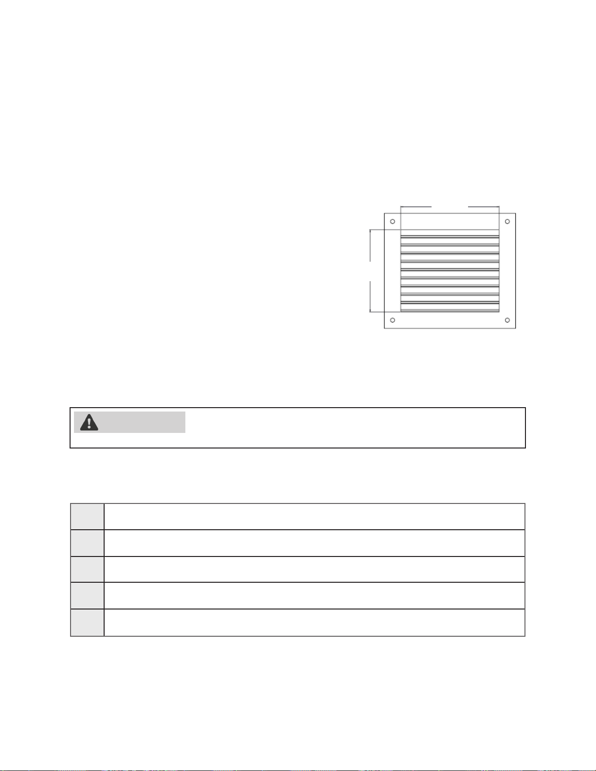
Louvers and Grills
2
2
Location
12 in.
10 in.
TO PREVENT POSSIBLE PERSONAL INJURY OR DEATH DUE TO AS-
INDUCED DRAFT APPLIANCES IS NOT ALLOWED.
Checklist for Combustion Air and Venting Requirements
WARNING
Rinnai Tankless Water Heater Installation and Operation Manual 46
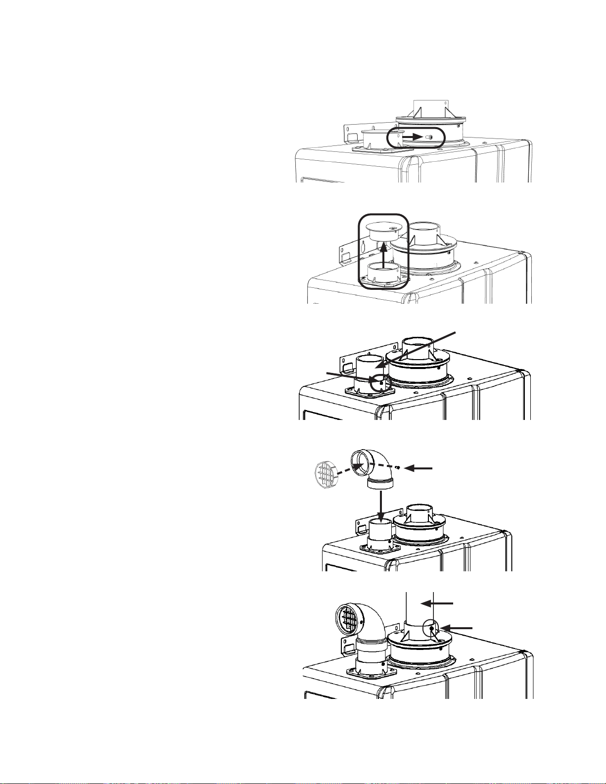
Vent Screen
Supplied
Room Air: Installation Instructions
1.
2.
(Figure 43).
3.
4.
Note:
•
•
5.
Figure 42
Figure 43
Figure 44
Figure 45
Figure 46
Rinnai Tankless Water Heater Installation and Operation Manual 47
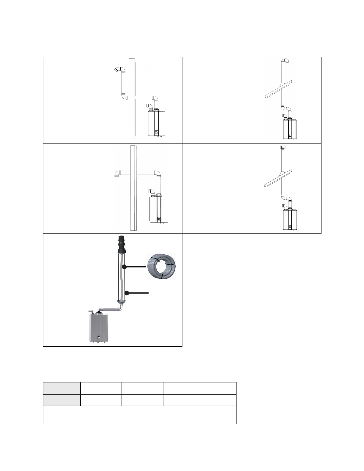
Room Air: Example Vent Applications
2 in. or 3 in. Schedule
40 PVC/CPVC or ABS
2 in. or 3 in. Schedule 40
PVC/CPVC or ABS Standard
2 in. or 3 in. Schedule 40
2 in. or 3 in. Schedule 40
PVC/CPVC or ABS Tee
details.
B-Vent Pipe
Vent Sizes
Vent Length
•
•
Room Air: Maximum Vent Length
Table 18
Rinnai Tankless Water Heater Installation and Operation Manual 48
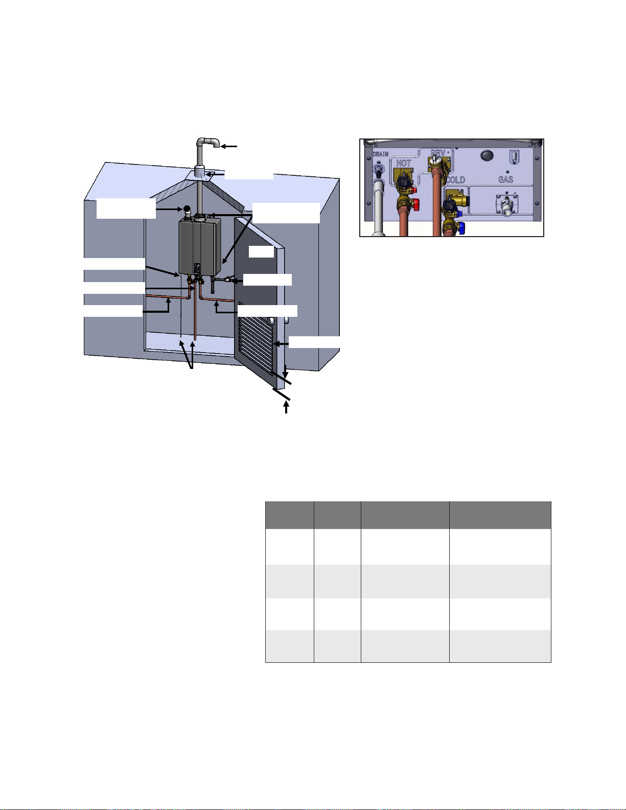
Room Air: Manufactured (Mobile) Home
Mounting Brackets
Vent Screen
Condensate Drain
Hot Water Outlet
Door
Cold Water Inlet
To Suitable Drain
Figure 47: Installation Enclosure with Louvered Door for
Manufactured Home Applications
•
the installation enclosure and the
•
incorporating a single opening
•
-
Model Input
Btu/h
Area
RU199i
200 in
2
2
)
RU180i
180 in
2
2
)
RU160i
160 in
2
2
)
RU130i
130 in
2
2
)
the opening in the access door.
Figure 48: Pipe connections on bottom
of water heater
Table 20
Rinnai Tankless Water Heater Installation and Operation Manual 49
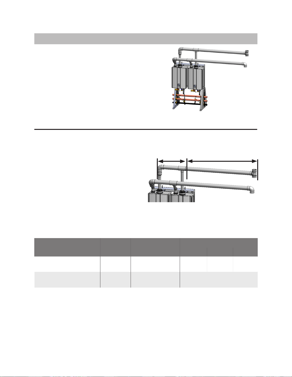
3. Common Vent (Indoor Units Only. Direct Vent and Non-Direct/Room Air Vent)
heater or appliance.
Common Vent Maximum Equivalent Vent Lengths
• -
•
•
Vent Length
Figure 49: Sample Inline, Freestanding
Conguration
Water Heater Model
# Water
Heaters
3 in. 4 in. 6 in.
RU199i (REU-N3237FF-US)
RU180i (REU-N2934FF-US)
2
RU160i (REU-N2530FF-US)
RU130i (REU-N2024FF-US)
2
Header
Figure 50
Rinnai Tankless Water Heater Installation and Operation Manual 50
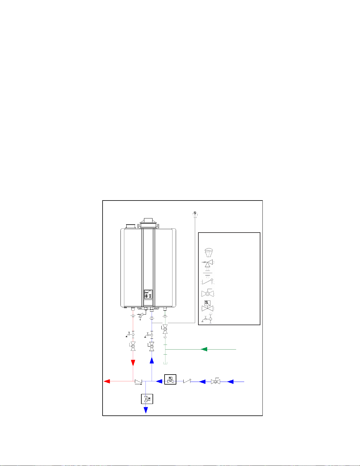
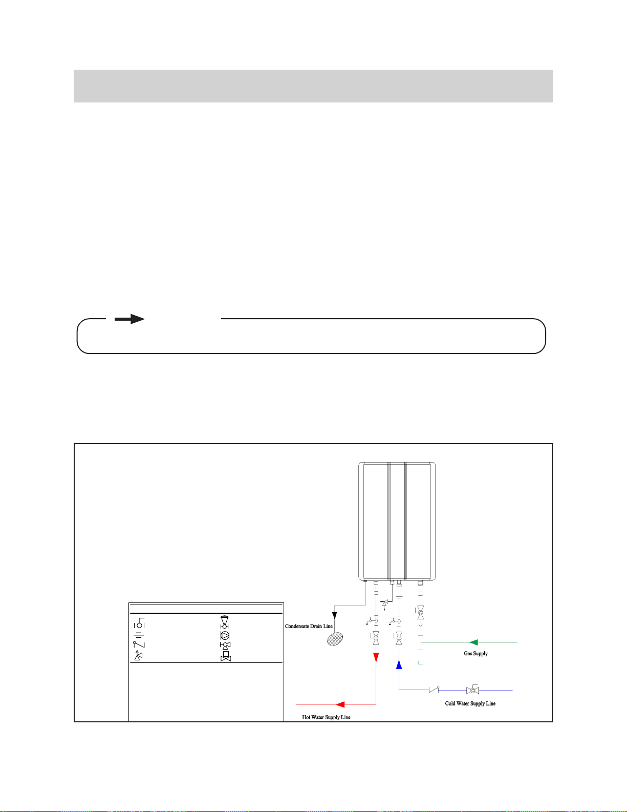
4.6 Connect Water Supply
4.6.1 Guidelines
•
•
•
•
•
4.6.2 Instructions
1.
2.
3.
G
a
s
S
u
p
p
l
3
/
4
"
C
o
l
d
W
a
t
e
r
S
u
p
p
l
L
i
n
e
3/4" Hot Water Supp Line
Rinnai
uipent List
Rinnai
Wa
ter Heaters
RIK-KIT (Optional)
(3/4" Fittings Include:
2 Union 2 Ball Vales
2 Draines and
1 Pressu
QTY
1
1
3
/
4
"
G
a
s
C
o
n
n
e
c
t
io
n
For Building Fitures
3/
3/4" Union
Check Va
S
Pressure Regulator
Circu
Solenoid
Boiler Drain Vale
KEY
This
o
Condensate drain line
Condensate
drain
G
a
s
S
u
p
p
l
3
/
4
"
C
o
l
d
W
a
t
e
r
S
u
p
p
l
L
i
n
e
3/
4" Hot Water Su
pp L
ine
Rinnai
uipent List
Rinnai
Water Heaters
RIK-KIT (Optional)
(3/4" Fittings Include:
2 Union 2 Ball Vales
2 Draines and
1 Pressu
QTY
1
1
3
/4
"
G
a
s
C
o
n
n
e
c
t
io
n
For Building Fitures
3/
3/4" Union
Check Va
S
Pressure Regulator
Circu
Solenoid
Boiler Drain Vale
KEY
This
o
Condensate drain line
Condensate
drain
The condensate drain pipe (along its entire
as the drain line (1/2 in. NPT).
PIPING DIAGRAM FOR BASIC INSTALLATION
Figure 51
IMPORTANT
Rinnai Tankless Water Heater Installation and Operation Manual 51
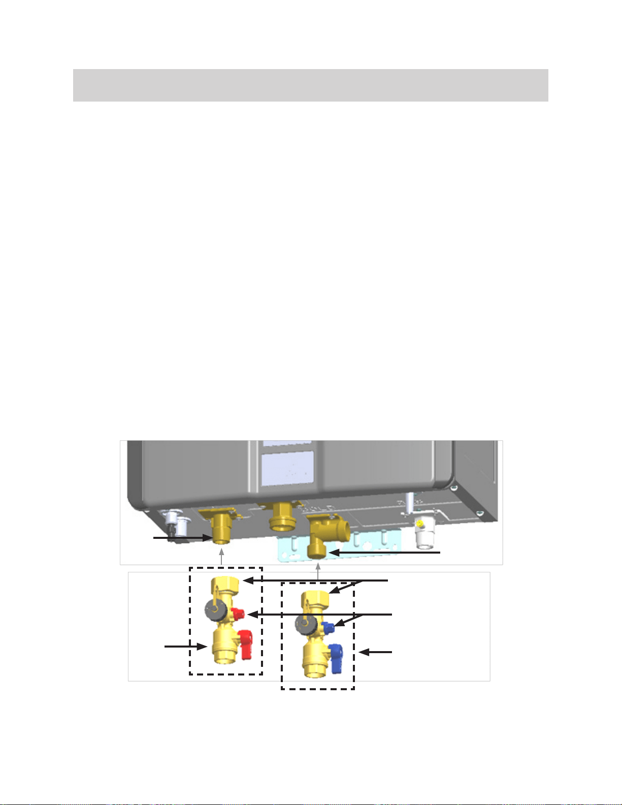
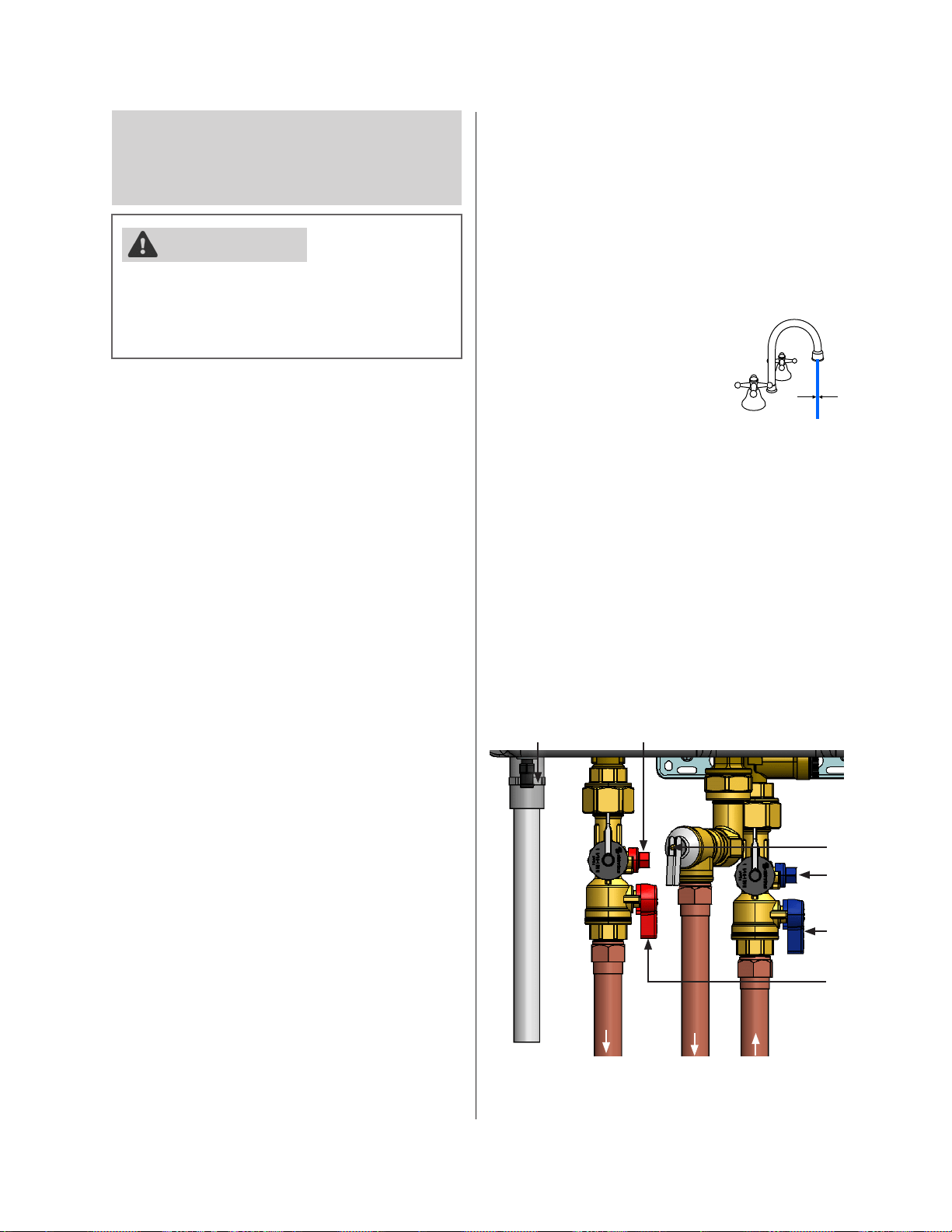
4.7 Install the Isolation Valves
4.7.1 Instructions
1. Position the Hot Isolation Valve (Red)Hot Outlet
2. Hand tighten the Swivel NutHot Isolation Valve (Red) to the Hot Outlet
heater.
3. Rotate the Drain ValveSwivel Nut
heater.
4. Cold Isolation Valve (Blue).
5. Connect the Cold Isolation Valve (Blue) to the Cold Water Supply Line.
6. Connect the Hot Isolation Valve (Red) to the Hot Water Supply Line.
7. Ensure that both Drain Valves
Hot Outlet
Cold Inlet
(Red)
(Blue)
Figure 52: Install Isolation Valves

Rinnai Tankless Water Heater Installation and Operation Manual 52
4.8 Install Pressure Relief Valve
4.8.1 Guidelines
•
-
-
•
•
• -
correct operation.
•
-
•
•
-
heater.
• -
-
-
•
•
•
•
-
•
WARNING
Rinnai Tankless Water Heater Installation and Operation Manual 53
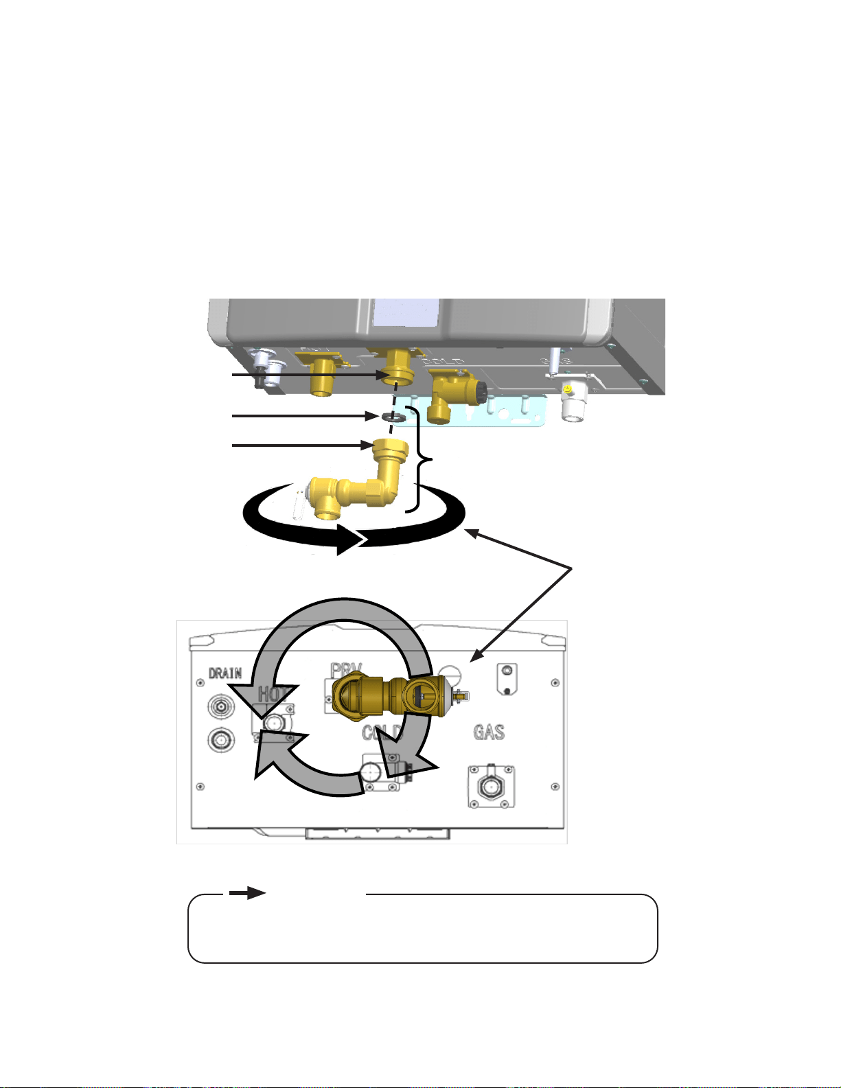
4.8.2 Instructions
1. Pressure Relief Valve Assembly and
Gasket to the Pressure Relief Valve Union Fitting.
2. Rotate the Pressure Relief Valve Assembly
tighten the Union Nut to the Pressure Relief Valve Union Fitting.
Union Fitting
Gasket
Union Nut
Pressure Relief Valve Assembly
application.
Figure 53: Pressure Relief Valve Assembly
•
•
IMPORTANT
Rinnai Tankless Water Heater Installation and Operation Manual 54
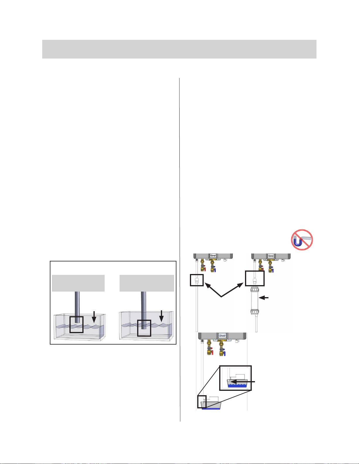
4.9 Connect Condensate Drain
4.9.1 Guidelines
guidelines:
•
• -
•
the condensate drain lines such as PVC
pipe or plastic hose.
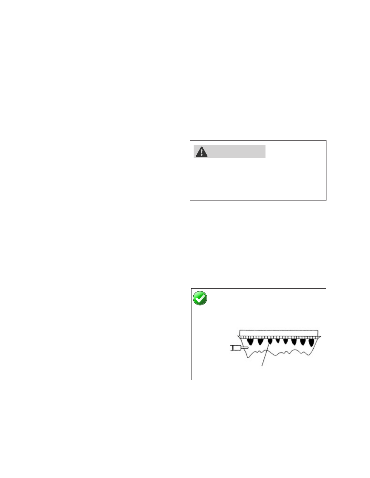
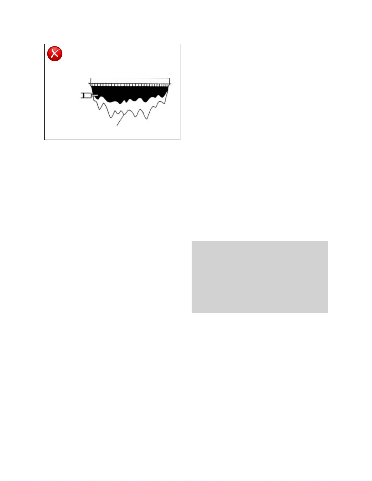
• The condensate drain pipe (along its entire
as the drain line (1/2 in. MNPT).
• Condensation drain lines installed in areas
-
-
•
•
substances.
• -
condensate drain line through an interior
•
Pipe open to
CORRECT INCORRECT
Water
Water
•
• The condensate drain pipe should be as
pitch.
•
-
is no blockage in the condensate drain. It
-
densate trap.
• DO NOT connect the condensate drain
drain.
•
condensate trap. DO NOT install
Neutralizer
Refer to neutralizer
Installation Manual
and local codes for
neutralizer installation
guidelines.
Pipe open to
Condensate
Pipe open to
Figure 54
Figure 55
Rinnai Tankless Water Heater Installation and Operation Manual 55
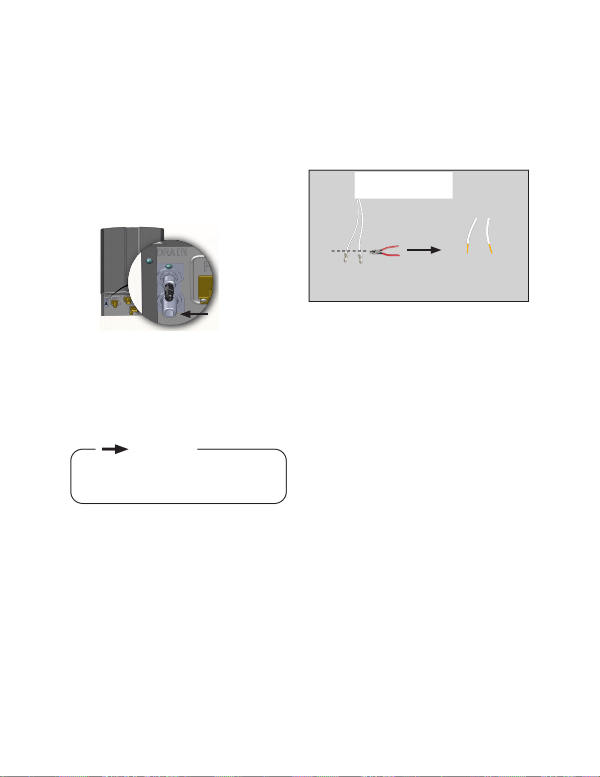
4.9.2 Instructions
To connect the condensate drain pipe:
1.
condensate drain port.
2.
drain port.
3.
4.9.3 Condensate Pump
Safety Switch Wiring
1.
2.
1/2 in. MNPT
Condensate Drain
Strip insulation
connectors
3.
4.
National Electrical Code (NEC).
5.
6.
Test Operation
1.
2.
3.
4.
5.
diagnostic code.
Figure 56
Figure 57
the National Electrical Code (NEC).
IMPORTANT
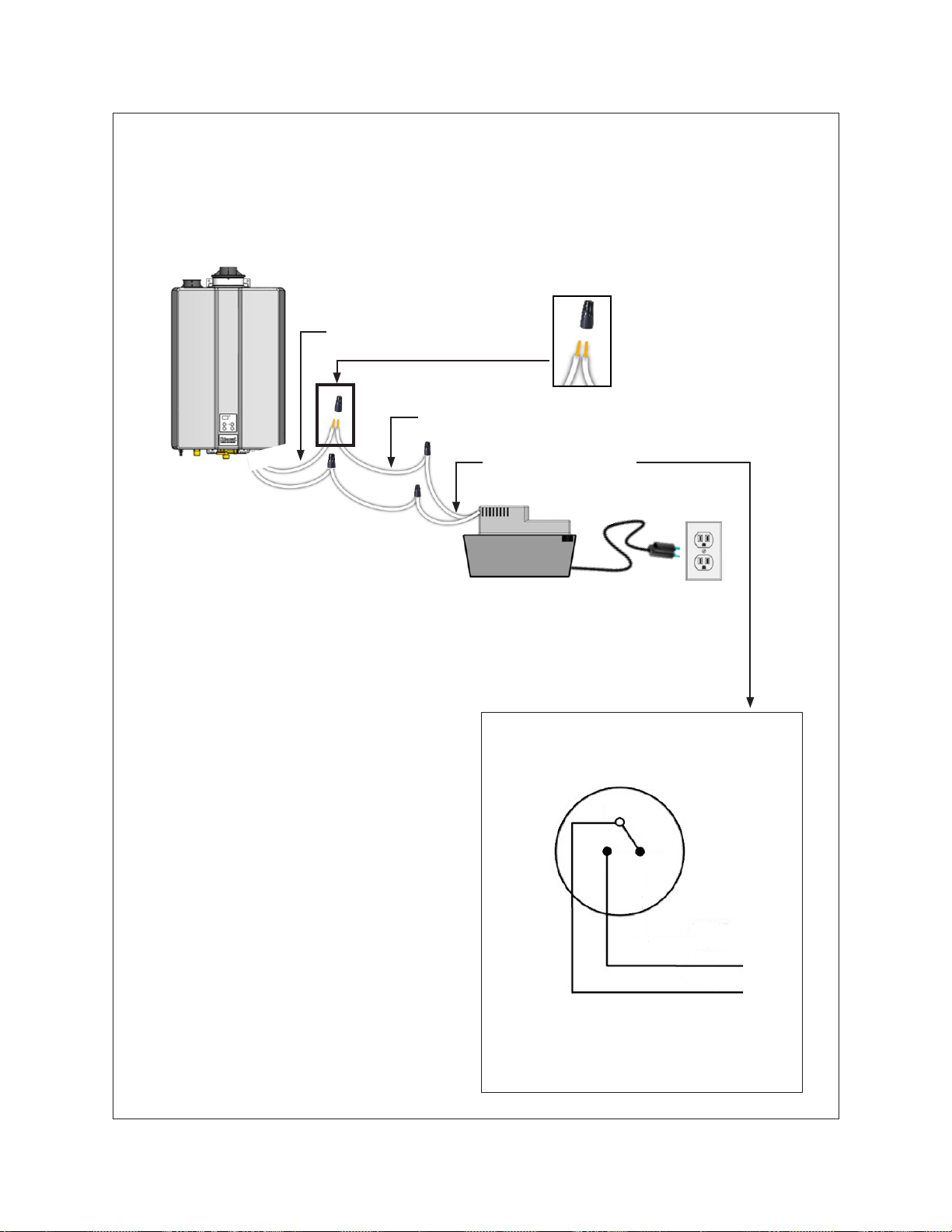
Rinnai Tankless Water Heater Installation and Operation Manual 56
NC
NO
COM
Tankless Water Heater
Wire Nut Connecting
Field-Supplied Wires
•
•
•
Condensate Pump Safety Switch Installation
Figure 58: Condensate Pump Safety Switch Installation
Rinnai Tankless Water Heater Installation and Operation Manual 57
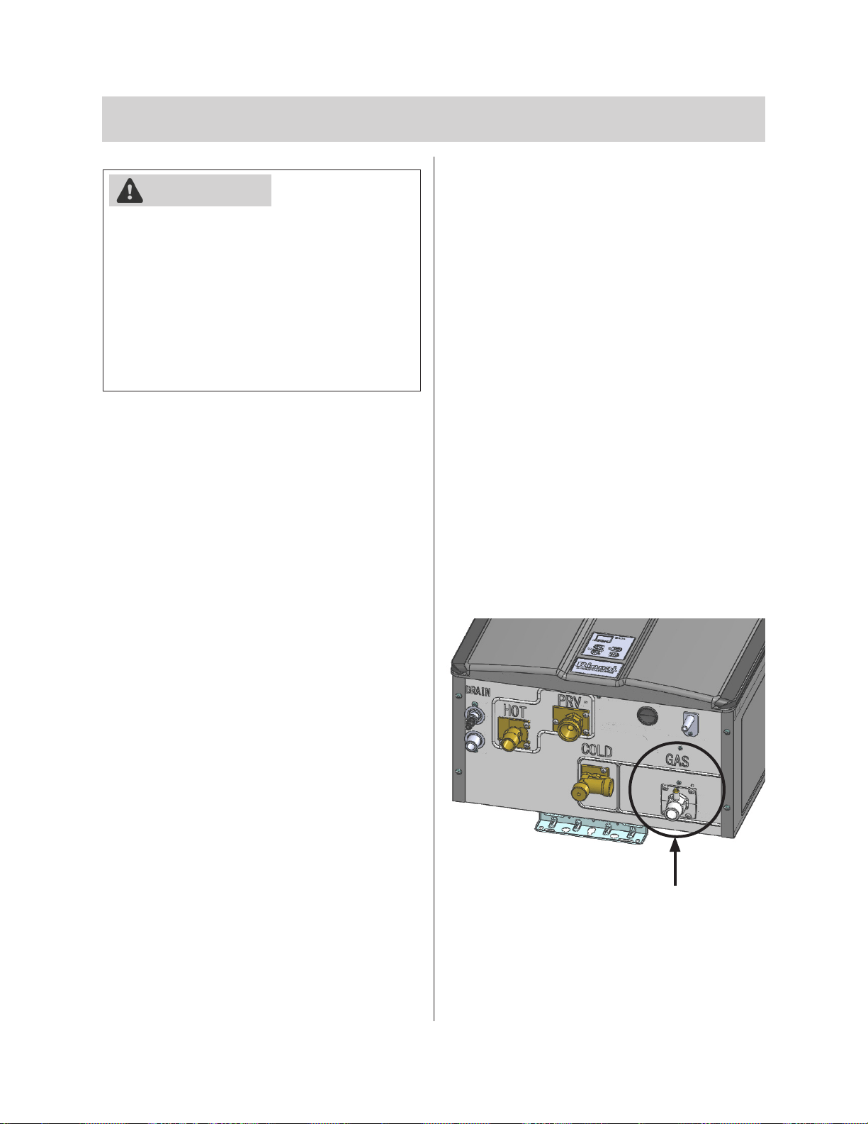
4.10 Connect the Gas Supply
Figure 59
•
•
•
• -
•
4.10.1 Instructions
1.
2.
3.
operating.
4.
WARNING
5.
heater.
6.
LPG).
7.
8.
the leak is repaired.
Gas connection 3/4 in.
MNPT connection
Rinnai Tankless Water Heater Installation and Operation Manual 58
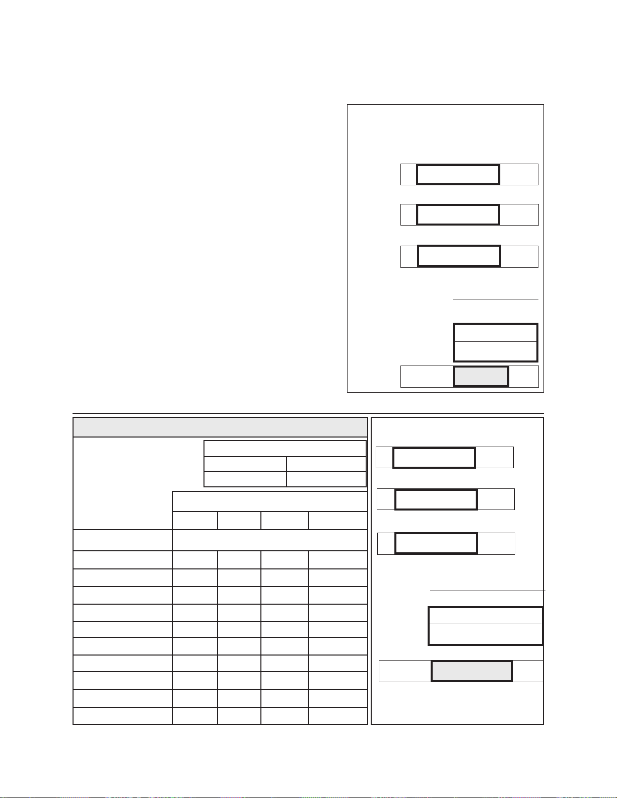
4.10.2 Gas Pipe Sizing Reference Tables
all gas products are in use.
Table 22: Gas Pipe Sizing Calculation
Worksheet
Rinnai Model Gas Input:
Additional Appliance Total Gas Input:
Cubic Feet Per Hour (CFH):
A Btu/hr
B Btu/hr
C
3
(CFH)
A + B
C
(CFH)
(CFH)
3
/hr
Natural Gas
Information in table
obtained from NFPA 54,
ANSI Z223.1 - 2015.
1/2 3/4 1 1 1/4
10 (3) 172 360 678
20 (6) 118 247 466 957
30 (9) 95 199 374 768
40 (12) 81 170 320 657
50 (15) 72 151 284 583
60 (18) 65 137 257 528
70 (21) 60 126 237 486
80 (24) 56 117 220 452
90 (27) 52 110 207 424
100 (30) 50 104 195 400
Schedule 40 Metallic Pipe
Inlet Pressure: Less than 2 psi
0.60
Rinnai Model Gas Input:
Additional Appliance Total Gas Input:
Cubic Feet Per Hour (CFH):
Answer:
A
199,000
Btu/hr
B
65,000
Btu/hr
C
1,000
3
(CFH)
A + B
C
(CFH)
199,000+65,000
1,000
(CFH)
264
3
/hr
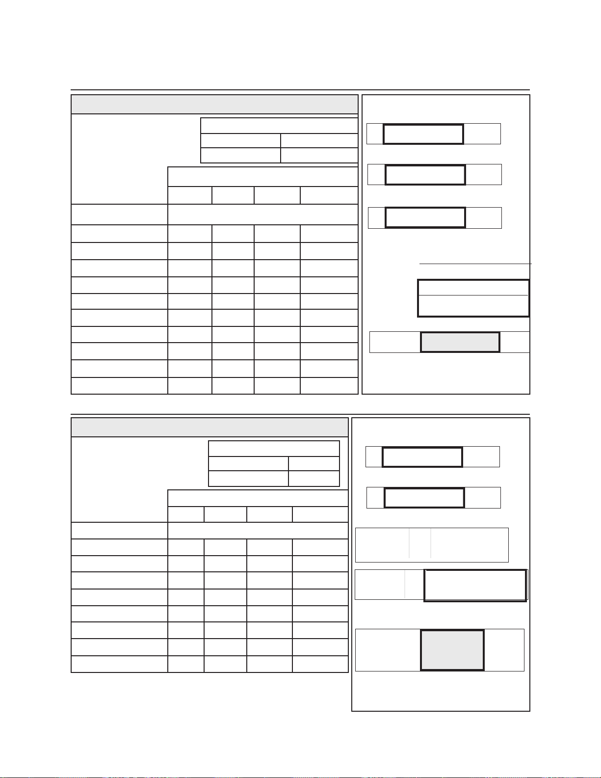
Rinnai Tankless Water Heater Installation and Operation Manual 59
or greater.
Information in table
obtained from NFPA 54,
ANSI Z223.1 - 2015.
1/2 3/4 1 1 1/4
10 (3) 454 949
20 (6) 312 652
30 (9) 250 524 986
40 (12) 214 448 844
50 (15) 190 397 748
60 (18) 172 360 678
70 (21) 158 331 624
80 (24) 147 308 580
90 (27) 138 289 544
100 (30) 131 273 514
Natural Gas
Rinnai Model Gas Input:
Additional Appliance Total Gas Input:
Cubic Feet Per Hour (CFH):
Answer:
A
199,000
Btu/hr
B
65,000
Btu/hr
C
1,000
3
(CFH)
A + B
C
(CFH)
199,000+65,000
1,000
(CFH)
264
3
/hr
Schedule 40 Metallic Pipe
Inlet Pressure: Less than 2 psi
0.60
Propane (Undiluted)
Information in table obtained from
NFPA 54, ANSI Z223.1 - 2015.
1/2 3/4 1 1 1/4
10 (3) 291 608
20 (6) 200 418 787
30 (9) 160 336 632
40 (12) 137 287 541
50 (15) 122 255 480 985
60 (18) 110 231 434 892
80 (24) 101 212 400 821
100 (30) 94 197 372 763
Schedule 40 Metallic Pipe
Inlet Pressure:
1.50
Rinnai Model Gas Input:
Additional Appliance Total Gas Input:
Total Gas Input:
Answer:
A
199,000
Btu/hr
B
65,000
Btu/hr
Total Gas
Input
264,000
Btu/hr
Total Gas
Input
=
A + B
Total Gas
Input
=
199,000 + 65,000
Rinnai Tankless Water Heater Installation and Operation Manual 60
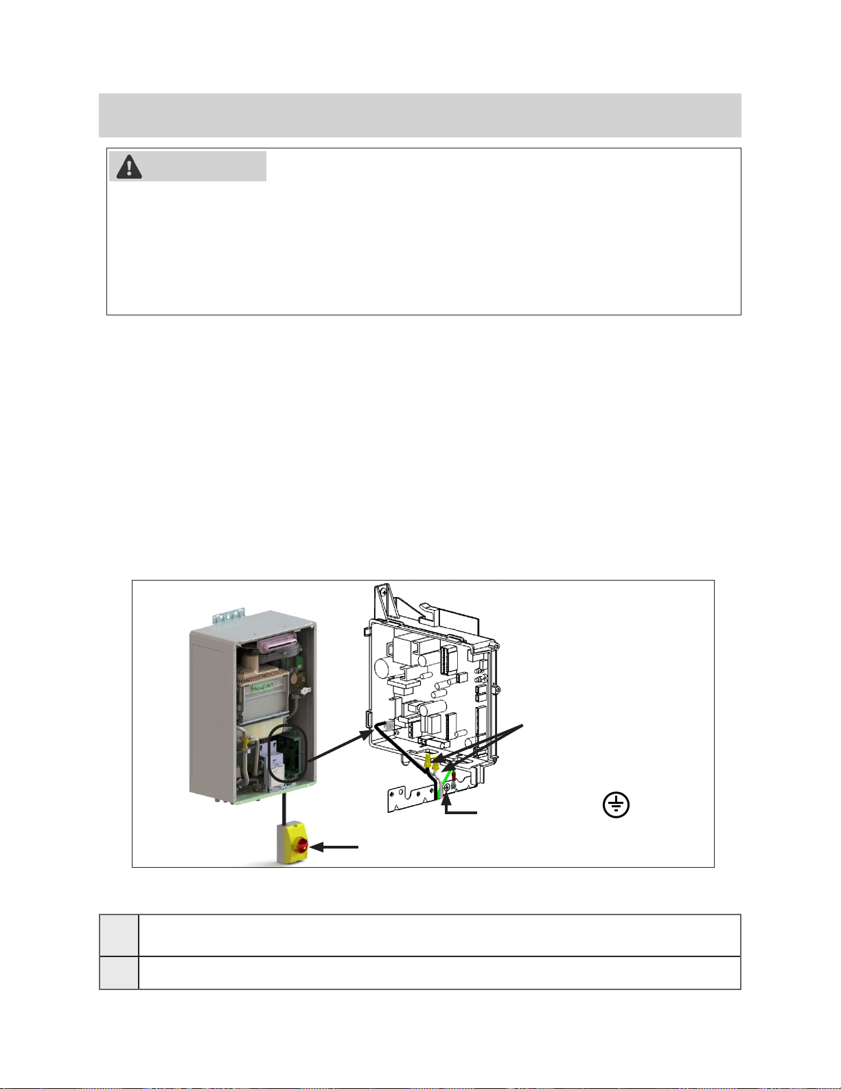
4.11 Connect the Power Supply
•
•
70.
•
4.11.1 Guidelines
•
•
•
• -
•
WARNING
120V Wiring
•
•
□
grounded circuit.
□
Post-Power Supply Connection Checklist
Ground connection
Figure 60
Rinnai Tankless Water Heater Installation and Operation Manual 61
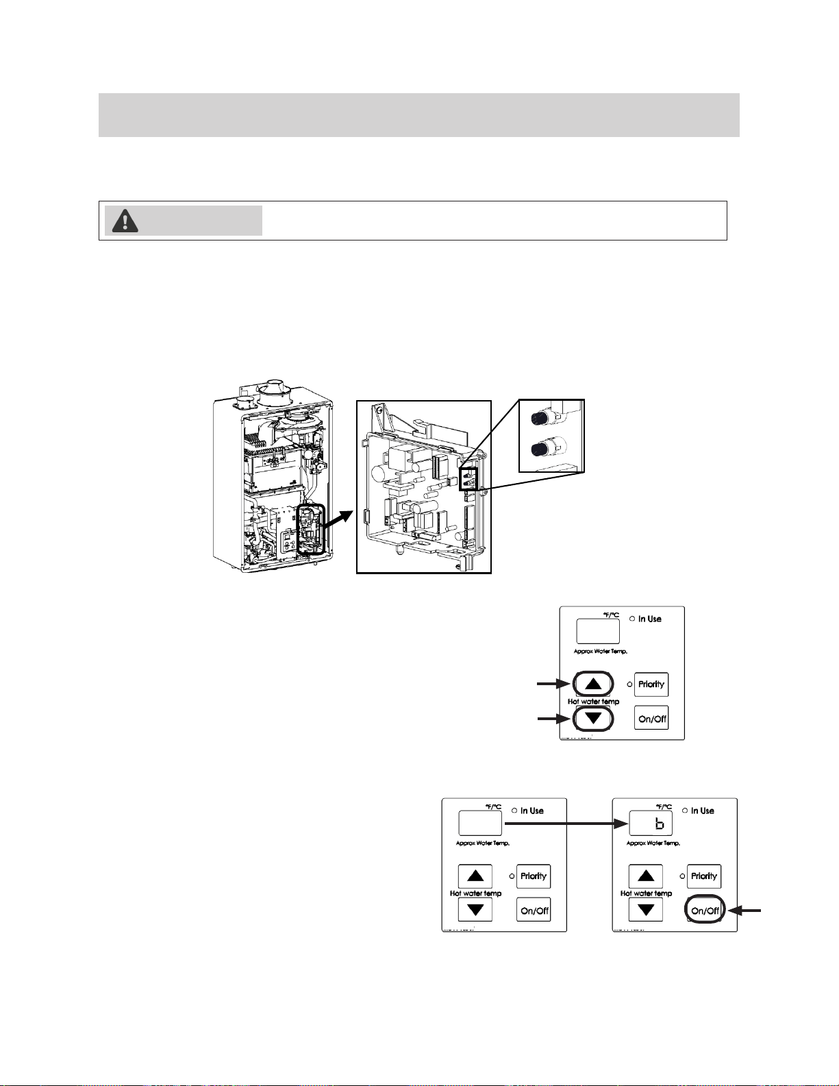
4.12 Configure Parameter Settings
4.12.1 Instructions
1.
2.
3.
WARNING
A
B
4.
5.
Example:
6.
second.
01A
01B
Figure 61
Figure 62
Figure 63
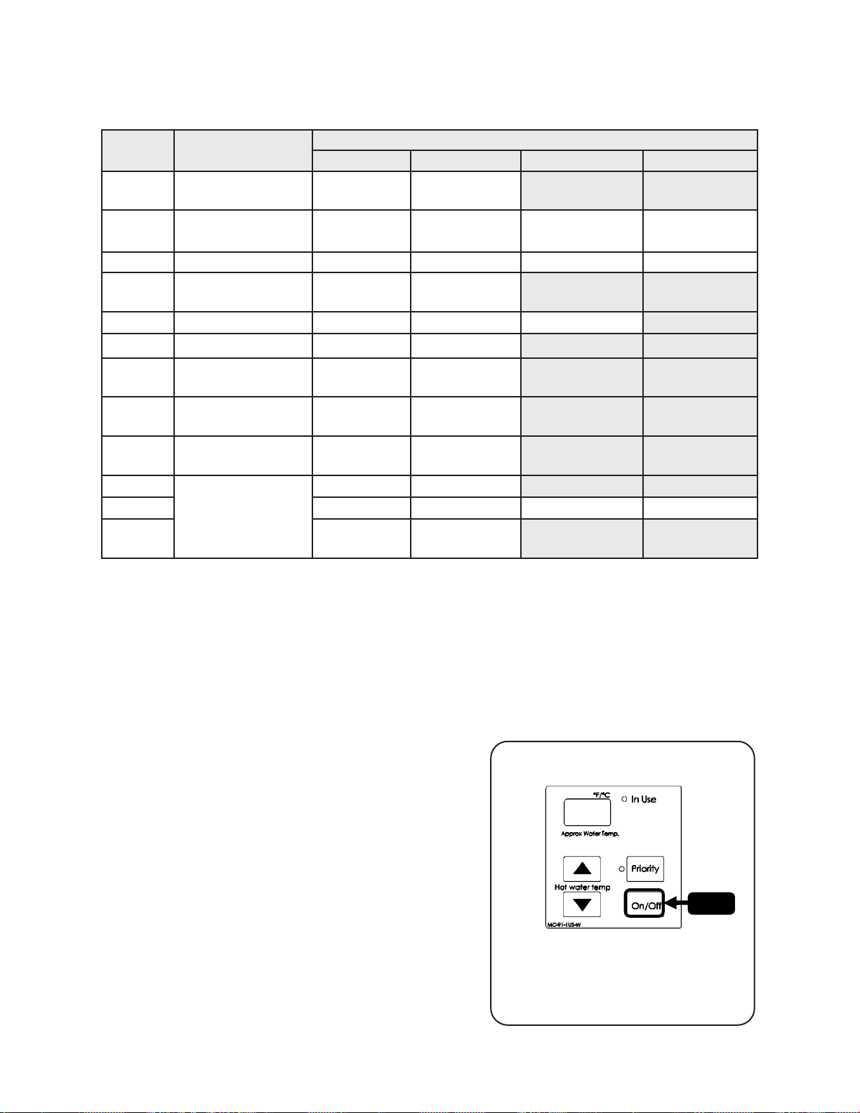
Rinnai Tankless Water Heater Installation and Operation Manual 62
SETTING
#
SETTING
DESCRIPTION
SELECTION
a b c d
01
02
High Altitude
Installation Location
03
1
Disabled 0.5 Year 1 Year 2 Years
04
Recirculation
Settings
No
Recirculation
Recirculation
(Dedicated)
05
Recirculation Mode
2
5
06
BMS
3
Air Handler (AH)
07
(EZConnect™)
2 1
10
NG LPG
11
Rate
4
Standard High
12
Water Heater Model
13
199 (3237) 180 (2934) 160 (2530) 130 (2024)
14
Internal
(Indoor)
(Outdoor)
A10121314
1
55.
2
Setting 0504b is selected.
Economy mode
Comfort mode
3
4
5
4.12.2 Service Indicator (Service Soon, SS)
5 TIM ES
55
SSSS
•
•
• SS) appears on the controller dis-
• -
To reset Service Soon (55)
55
Figure 64
Rinnai Tankless Water Heater Installation and Operation Manual 63
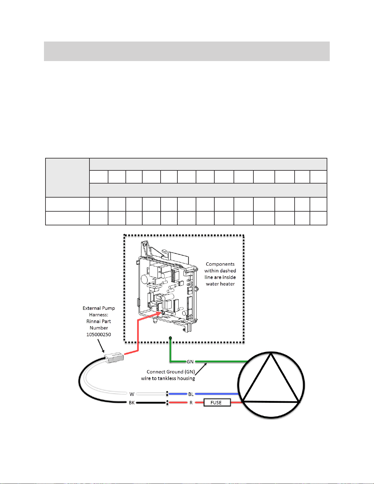
4.13 External Pump with Circ-Logic
•
•
Rinnai Set Temperature
140 135 130 125 120 115 110 108 106 104 102 100 98
Typical Pump OFF Intervals (Minutes)
Economy 18 20 22 24 28 32 38 40 44 48 52 56 62
Comfort 9 10 11 12 14 16 19 20 22 24 26 28 31
Figure 65
Table 30
Rinnai Tankless Water Heater Installation and Operation Manual 64
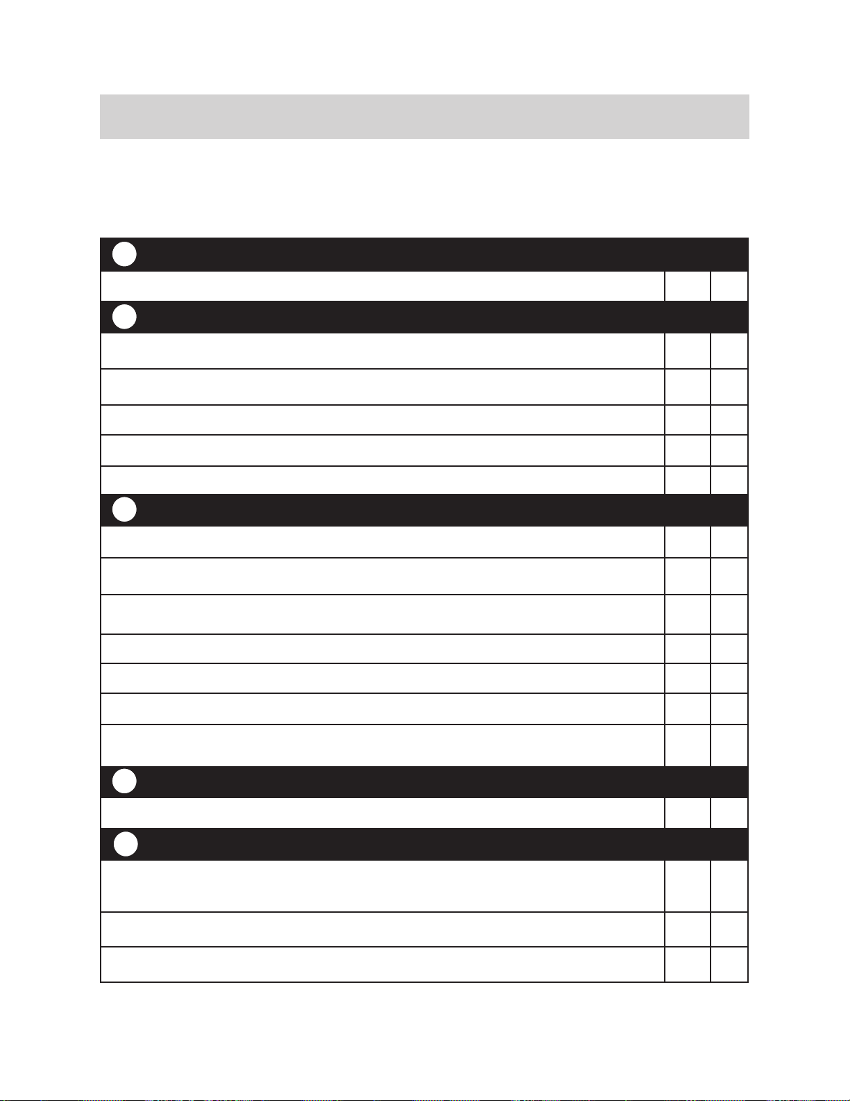
4.14 Post-Water Heater Installation Checklist
INSTALLATION LOCATION YES NO
□ □
COMBUSTION AIR & VENTING YES NO
□ □
□ □
□ □
□ □
□ □
PLUMBING YES NO
□ □
□ □
□ □
□ □
□ □
□ □
□ □
ISOLATION VALVES YES NO
□ □
PRESSURE RELIEF VALVE (PRV)
□ □
□ □
□ □
4
3
2
1
5
Rinnai Tankless Water Heater Installation and Operation Manual 65
□ □
□ □
□ □
□ □
is not
□ □
is not
□ □
CONDENSATE DRAIN YES NO
□ □
□ □
□ □
□ □
□ □
□ □
□ □
□ □
□ □
has an integrated condensate trap.)
□ □
□ □
GAS SUPPLY YES NO
□ □
□ □
□ □
□ □
□ □
□ □
7
6
AVERTISSEMENT
WARNING
Rinnai Tankless Water Heater Installation and Operation Manual 66
5. 5. OperationOperation
Topics in this section
•
•
• Control Panel
• Basic Operation Settings
• Diagnostic Codes
5.1 Safety
Precautions
If the information in these instructions is
not followed exactly, a re or explosion may
result causing property damage, personal
injury, or death.
• -
• -
• WHAT TO DO IF YOU SMELL GAS
–
–
–
–
•
Assurez-vous de bien suivre les instructions
données dans cette notice pour réduire au
minimum le risque d’incendie ou d’explosion
ou pour éviter tout dommage matériel, toute
blessure ou la mort.
•
-
autre appareil.
•
• QUE FAIRE SI VOUS SENTEZ UNE
ODEUR DE GAZ :
–
–
-
– -
– -
•
gaz.

Rinnai Tankless Water Heater Installation and Operation Manual 67
• Keep the area around the appliance clear
•
(N’utilisez pas cet appareil s’il a été plongé
dans l’eau, même partiellement. Faites
inspecter l’appareil par un licence pro-
fessionnelle et remplacez toute partie du
système de contrôle et toute commande
qui ont été plongés dans l’eau.)
• -
(En cas de surchaue ou si l’alimentation
en gaz ne s’arrête pas, fermez manuelle-
ment le robinet d’arrêt de l’admission de
gaz.)
•
•
• -
• -
•
• -
• -
• -
Rinnai Tankless Water Heater Installation and Operation Manual 68
5.2 Operating Instructions
FOR YOUR SAFETY READ BEFORE OPERATING
OPERATING INSTRUCTIONS
1.
2.
3.
4.
5.
position.
6.
7.
position.
8.
9.
setting.
10.
TURN OFF GAS TO APPLIANCE
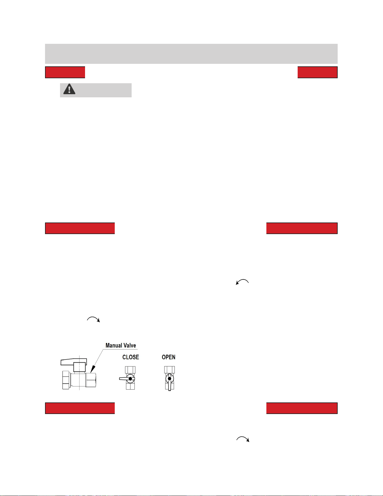
1.
2.
3.
position.
WARNING
A.
-
B.
WHAT TO DO IF YOU SMELL GAS
•
•
•
instructions.
•
C.
D.
-
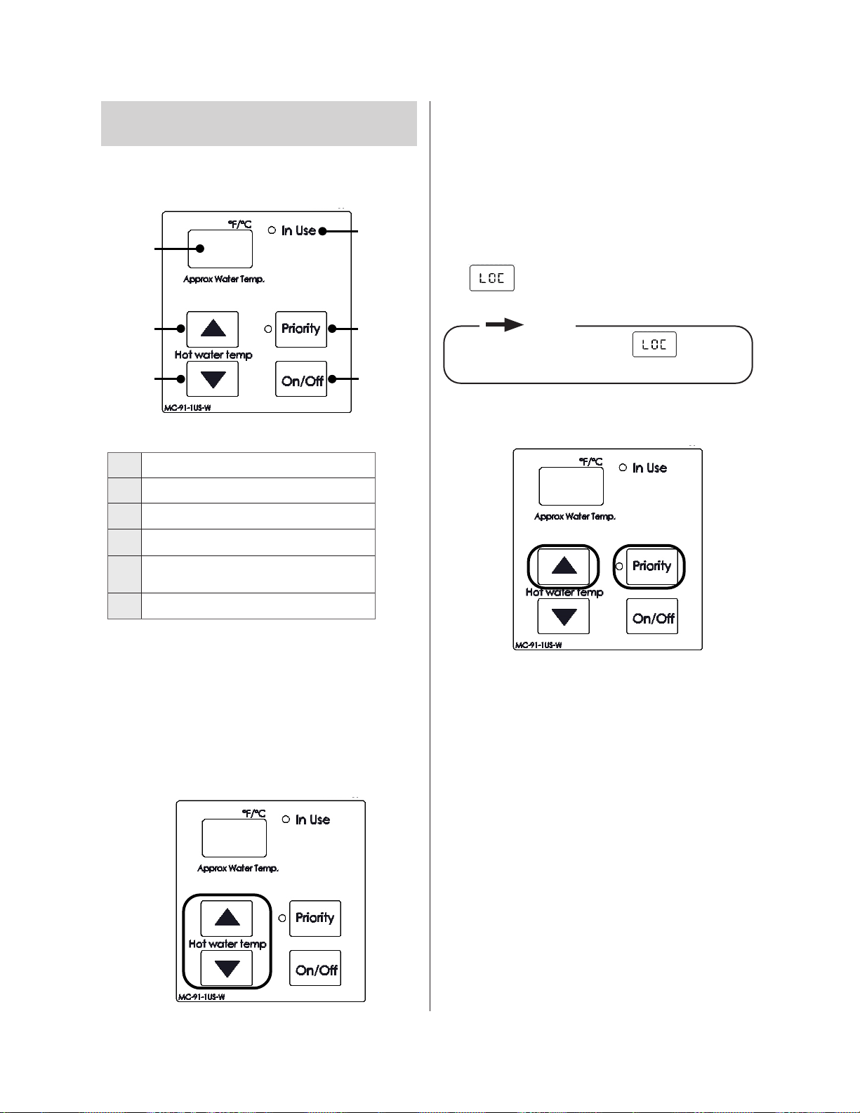
Figure 67
Figure 68
Rinnai Tankless Water Heater Installation and Operation Manual 69
controllers are used
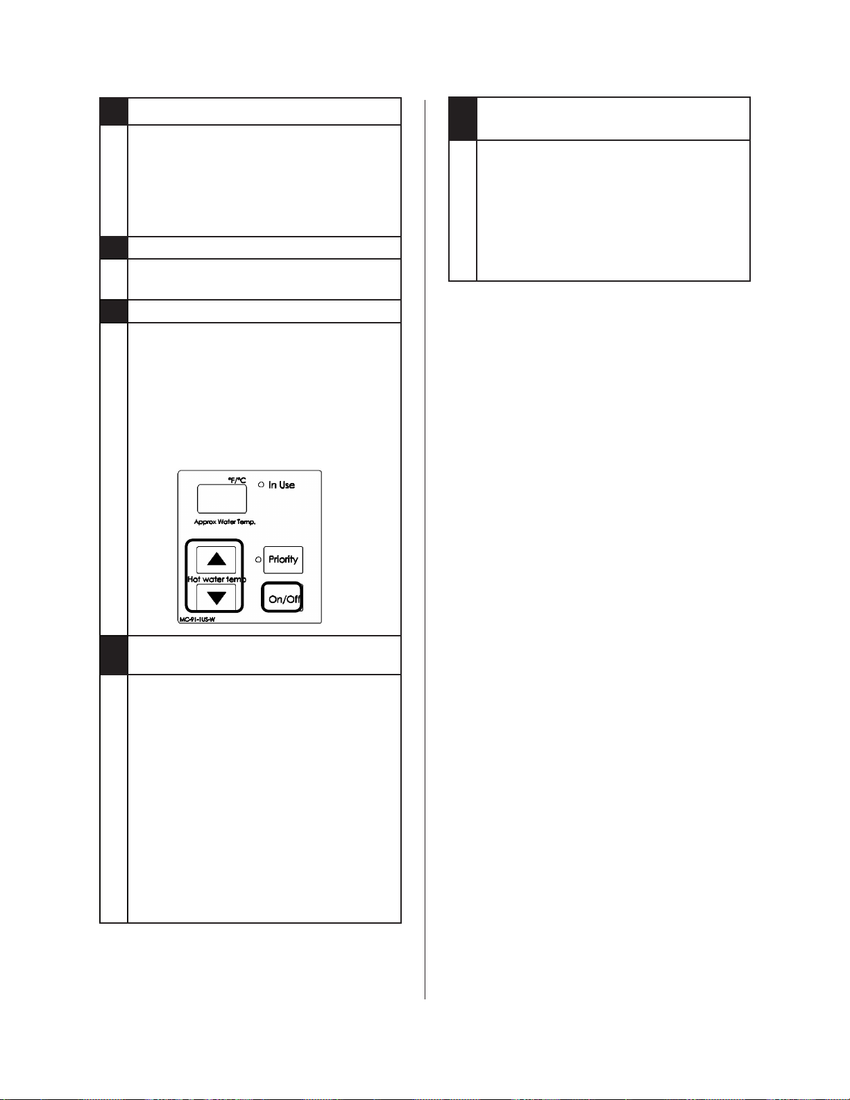
5.3 Control Panel
5.3.1 Setting the Controller to
Mute
press and hold both the (Up) and
buttons.
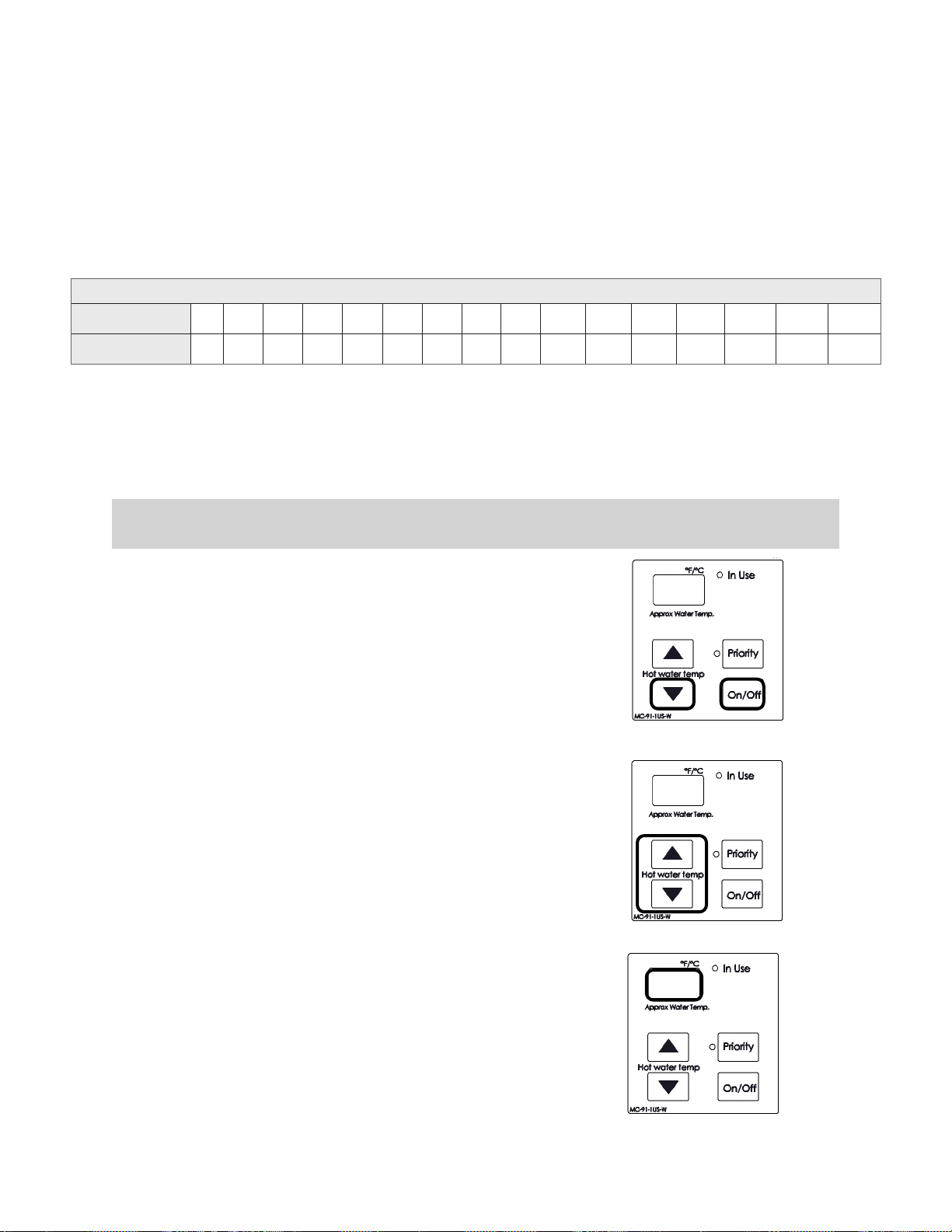
5.3.2 Locking the Controller
1.
2.
press the (Up) button until a beep is heard
3.
controller is locked.
NOTE
Figure 66
Table 31
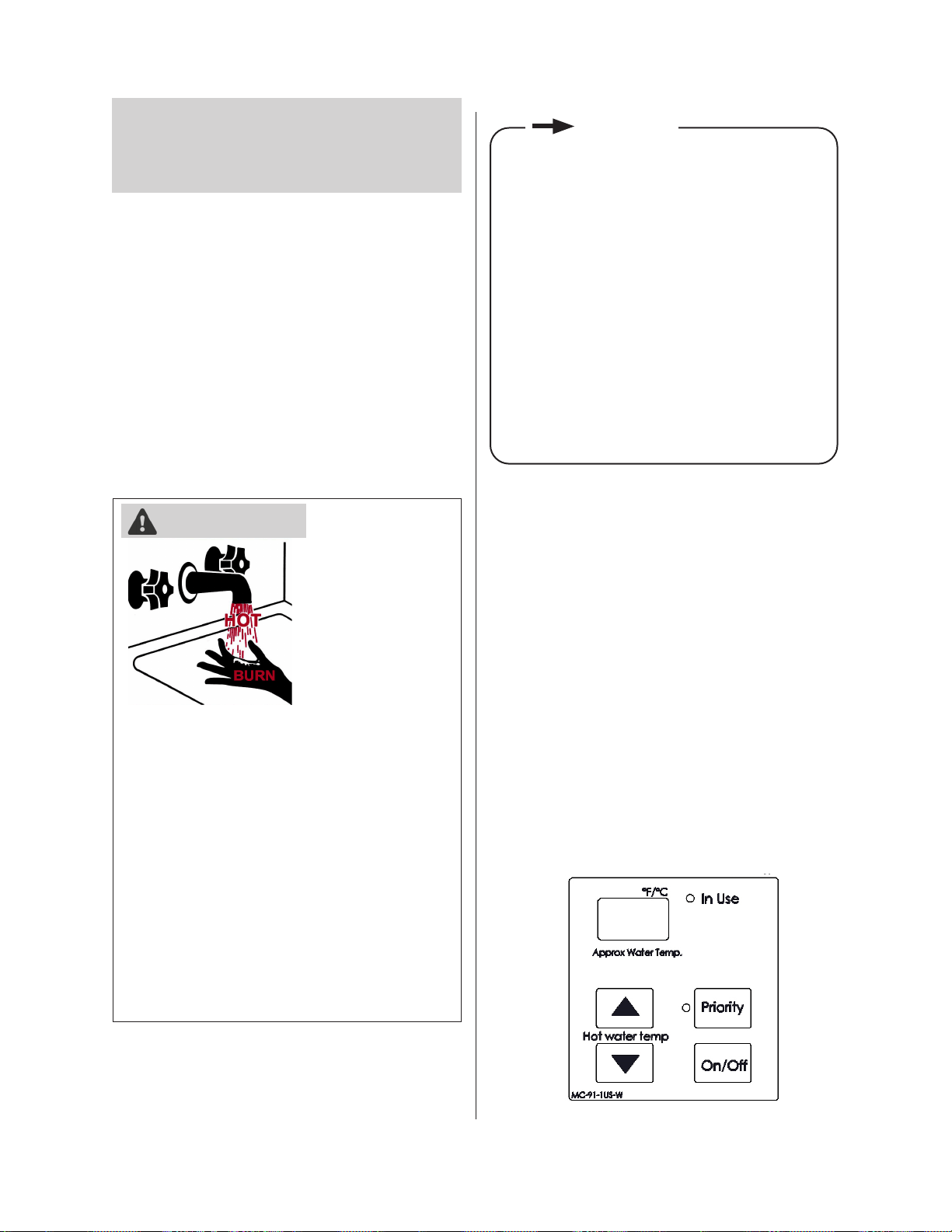
Figure 69
Rinnai Tankless Water Heater Installation and Operation Manual 70
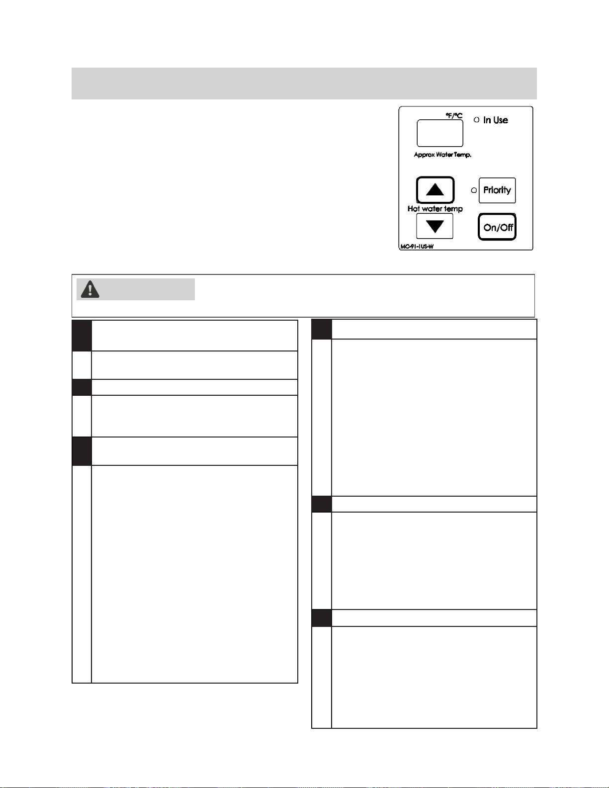
5.4 Setting the
Temperature
death.
•
•
•
1.
button to turn on.
2.
3. Press the (Up) or
controller.
DANGER
•
•
-
•
-
•
IMPORTANT
Temperature Settings
98 100 102 104 106 108 110 115 120 125* 130* 135* 140* 150** 160** 185**
37 38 39 40 41 42 43 46 49 52 54 57 60 66 71 85
Figure 70
Figure 71
Figure 72
Rinnai Tankless Water Heater Installation and Operation Manual 71
5.4.1 Available Temperatures with an Internal Controller
5.5 Performance Data
To obtain performance data:
1. Press and hold the
2. While holding the
3. Use the (Up) and
4.
5.
Table 32
Rinnai Tankless Water Heater Installation and Operation Manual 72
# Data Unit
01
02
03
04
*
05
Hz
06
Additional Controllers Connected *
07
08
09
Fan Current
10
Gallons
11
12
15
17
19
20
*
21
WARNING
Figure 72
Rinnai Tankless Water Heater Installation and Operation Manual 73
5.6 Diagnostic Codes
To display diagnostic codes:
(Up) button
the
03
Power interruption during bath ll
(Water will not ow when power returns)
•
05
By-Pass Flow Control
•
•
10
Air Supply or Exhaust Blockage/
Condensate Trap is Full
• Ensure condensate line is not blocked.
•
no obstructions. (Indoor Water Heaters
• Ensure High Altitude setting. (See
•
•
•
•
11
No Ignition (Heater Not Turning On)
• Check that the gas is turned on at the
•
gas is in the tank.
•
are correct.
•
•
•
• Ensure igniter is operational.*
•
short circuits.*
•
12
No Flame
• Check that the gas is turned on at the
•
gas is in the tank.
•
•
is correct.
•
14
Heat Exchanger Overheat
•
•
scale build-up.
•
•
Rinnai Tankless Water Heater Installation and Operation Manual 74
15
Venturi Control
•
•
•
16
High Outgoing Temperature
(safety shutdown because water heater
is too hot)
•
•
17
Venturi Blockage
•
•
blocked.
•
19
Electrical Grounding
•
short.
21
Data Transfer Error
•
25
Condensate Pump (Accessory)
•
are good.
•
32
Outgoing Thermistor
•
•
•
•
33
Heat Exchanger Thermistor
•
troubleshooting.
38
Exhaust Thermistor
•
•
• Replace sensor.
41
Freeze Protection Thermistor
•
troubleshooting.
51
Inlet Thermistor
•
•
•
• Replace sensor.
52
Gas Valve
•
•
short circuit.*
•
• Please call Rinnai technical
54
High Exhaust Gas Temperature
•
and not blocked.
•
too high.
•
heater.
61
Combustion Fan
•
•
harness.*
•
63
Recirculation Low Flow
•
•
debris.
•
•
•
recirculation line.
65
Water Flow Control
•
•
70
PC Board
• Replace PC Board
Rinnai Tankless Water Heater Installation and Operation Manual 75
71
Solenoid Valve Circuit
•
the OFF position.
•
• Ensure heater circuit is not grounded.
• Replace PC Board.
72
Flame Rod
•
•
FF
Maintenance Indicator
•
•
• FF
SS
(SS) Service Soon (Flush Heat
Exchanger)
• SS
details on setting and changing the SS
indicator.
• SS
Hard water must
be treated to prevent scale build-up
or damage to the heat exchanger.
• To reset the SS
FF
NO CODE - Nothing happens when
water ow is activated
•
•
•
•
troubleshooting resources.
Rinnai Tankless Water Heater Installation and Operation Manual 76
6. 6. MaintenanceMaintenance
Topics in this section
• Maintenance
• Cleaning and Inspecting the Air Filter
•
• Draining the Water Heater
6.1 Maintenance
• -
•
•
-
CLEANING
appliance be kept clean.
BURNER
1.
to cool.
2.
3.
4.
CONDENSATE COLLECTION AND
DISPOSAL SYSTEM
VENT SYSTEM
MOTORS
WARNING
WARNING
WARNING
FRONT VIEW
Flame Rod
Blue Flame
SATISFACTORY
Figure 73
Rinnai Tankless Water Heater Installation and Operation Manual 77
TEMPERATURE CONTROLLER
LIME/SCALE BUILD-UP
SNOW ACCUMULATION
obstructions.
ice. Ensure the line is not blocked or clogged and
COASTAL INSTALLATIONS
FILTERS
•
•
PRESSURE RELIEF VALVE
VISUAL INSPECTION OF FLAME
UNSATISFACTORY
FRONT VIEW
Flame Rod
Yellow Flame
Figure 74
Rinnai Tankless Water Heater Installation and Operation Manual 78
FREEZE PROTECTION
4.2 Choose an Installation Location > Freeze
WINTERIZATION
•
•
•
Gas
Water
•
not going to be used.
•
•
Condensate
Drain the condensate using the condensate drain
Electric
interruptions.
6.2 Cleaning and
Inspecting the Air
Filter (Indoor Units
Only)
INSPECTION
•
•
•
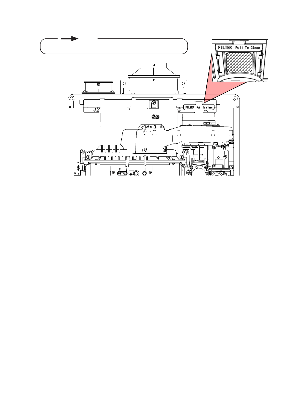
Figure 75
Rinnai Tankless Water Heater Installation and Operation Manual 79
CLEANING
1.
•
2.
•
•
•
3. Clean the Air Filter
•
•
4.
5. Inspect and Replace the Air Filter
•
•
•
6.
NOTE
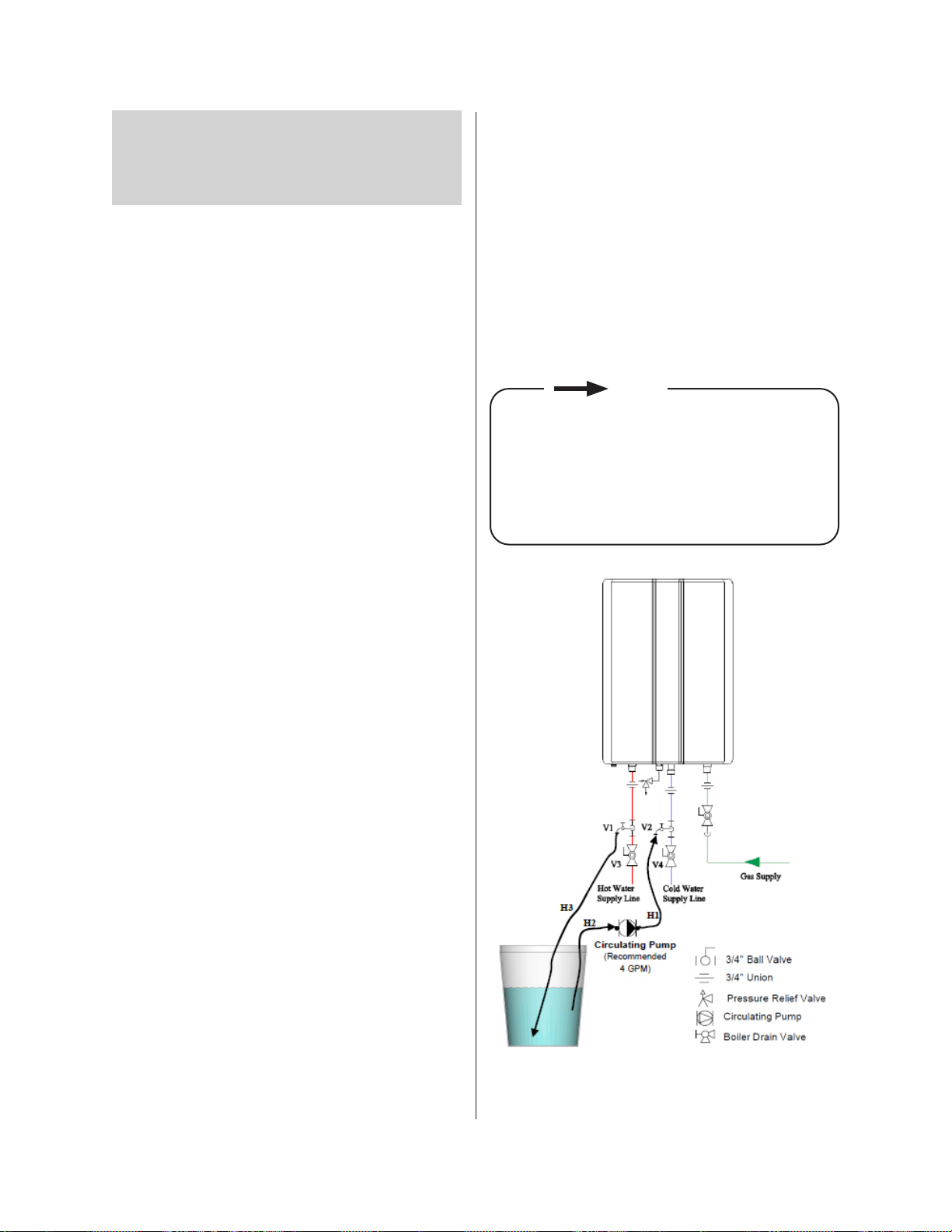
Figure 76
Rinnai Tankless Water Heater Installation and Operation Manual 80
6.3 Flushing the Heat
Exchanger
SS). When selected in
SS
1.
2.
heater.
3.
4.
5.
6.
7. Place the drain hose (H3) and the hose (H2)
8.
9.
10.
11.
E.
drain.
F.
G. -
H.
I.
12. Disconnect all hose
13.
NOTE
HOT
COLD
ON!
Cold Drain
Cold Isolation
Hot Isolation
Hot Drain
Condensate
Trap Drain Plug
Condensate
HOT
PRV
COLD
Figure 77: Piping Diagram
Rinnai Tankless Water Heater Installation and Operation Manual 81
6.4 Draining the Water
Heater
WARNING
heater be drained.
To manually drain the water:
1.
2.
3.
4.
5.
6.
7.
To resume normal operation:
1.
2. Insert the condensate trap drain plug.
3.
4.
5.
then close.
6.
7.
8.
Running a low volume of water through the
water heater to prevent freezing:
1.
2.
When the water heater or
external piping has frozen:
1.
2.
3.
4.
leaks.

Rinnai Tankless Water Heater Installation and Operation Manual 82
3.
“GAS
VENT DIRECTLY BELOW. KEEP CLEAR OF
ALL OBSTRUCTIONS.”
4. INSPECTION. The state or local gas
detectors and signage installed in accordance
through 4.
7. 7. AppendicesAppendices
Topics in this section
• Massachusetts State Gas Regulations
•
•
•
•
Controllers
7.1 Massachusetts State
Gas Regulations
For Gas Models Sold in Massachusetts
NOTICE BEFORE INSTALLATION:
IMPORTANT: In the State of Massachusetts
(248 CMR 4.00 & 5.00):
1. INSTALLATION OF CARBON MONOXIDE
DETECTORS.
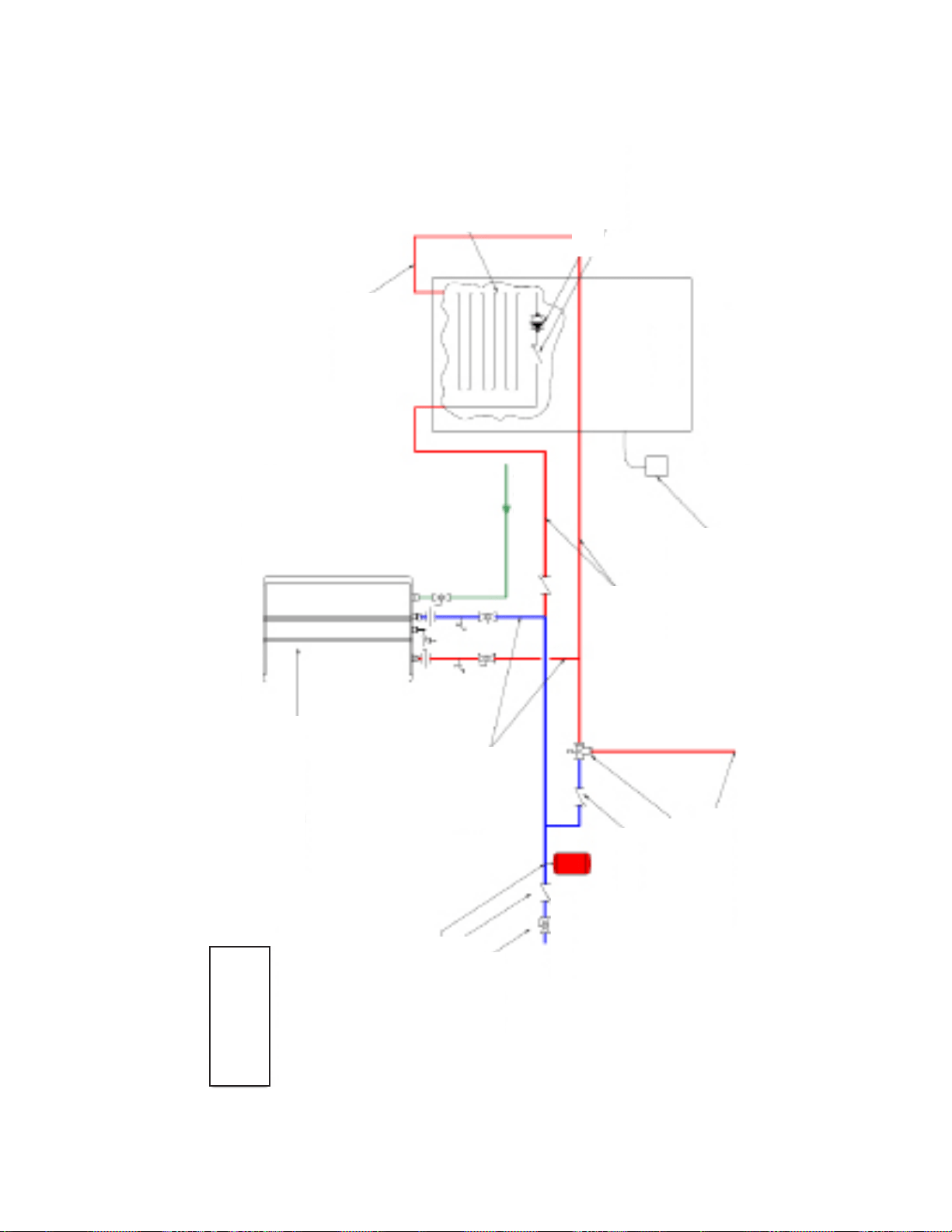
Figure 78
Rinnai Tankless Water Heater Installation and Operation Manual 83
COMBINATION SPACE HEATING/POTABLE WATER SYSTEM
(For Use In Commonwealth of Massachusetts)
Heating/Potable
780 CMR (Massachusetts
Drilled in Clapper Optional
Min. 2'
Hot Water
Return to
Heating Coil
seconds. Wire to product
including coil in heating unit.
Hot Water Coil
NSF-61 Product
Air Handler
Water Heater
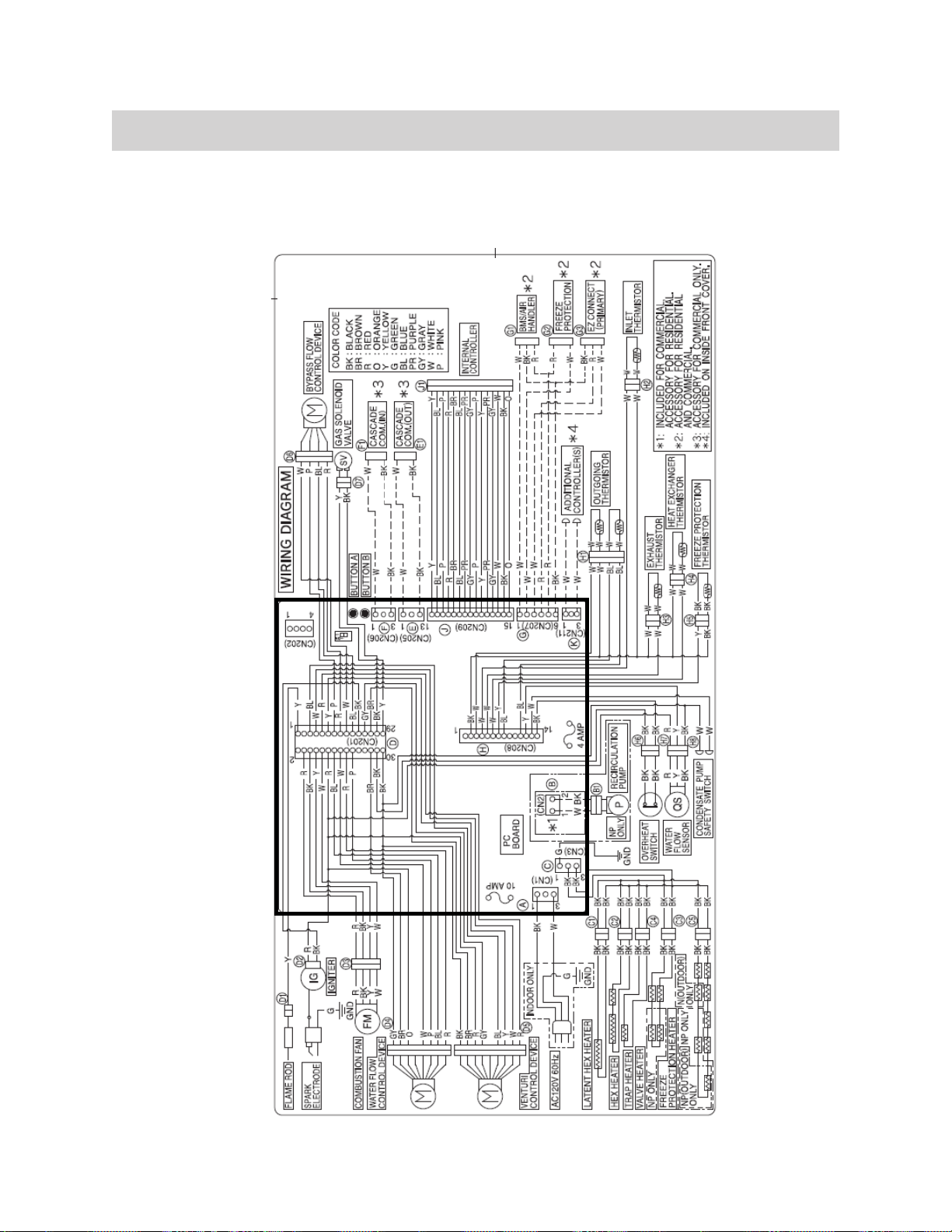
Figure 79
Rinnai Tankless Water Heater Installation and Operation Manual 84
7.2 Wiring Diagram
PC BOARD
Rinnai Tankless Water Heater Installation and Operation Manual 85
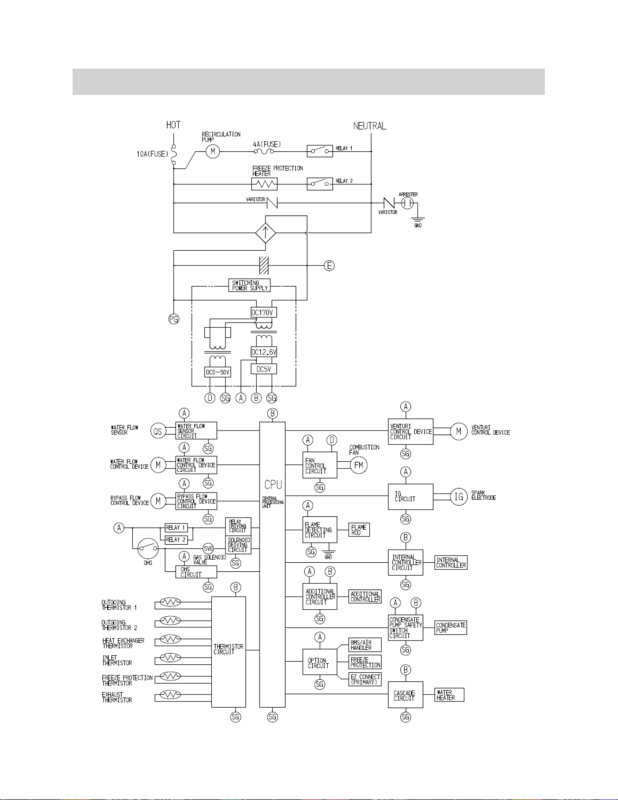
7.3 Ladder Diagram
Figure 80
Rinnai Tankless Water Heater Installation and Operation Manual 86
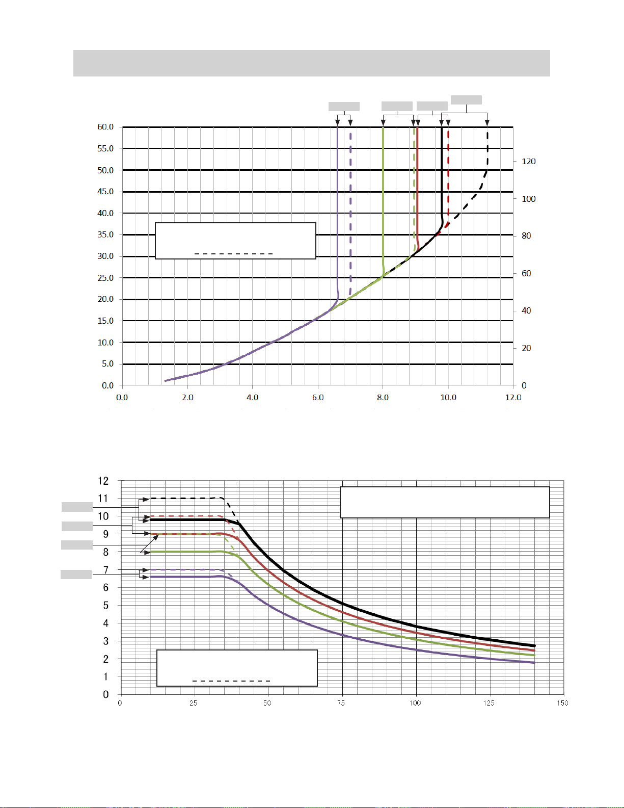
7.4 Pressure Drop and Water Flow Curves
Pressure Loss (PSI)
RU160
RU130
RU180
RU199
RU180
RU199
RU160
RU130
Figure 81: Pressure Drop Curve
Figure 82: Water Flow Curve
Rinnai Tankless Water Heater Installation and Operation Manual 87
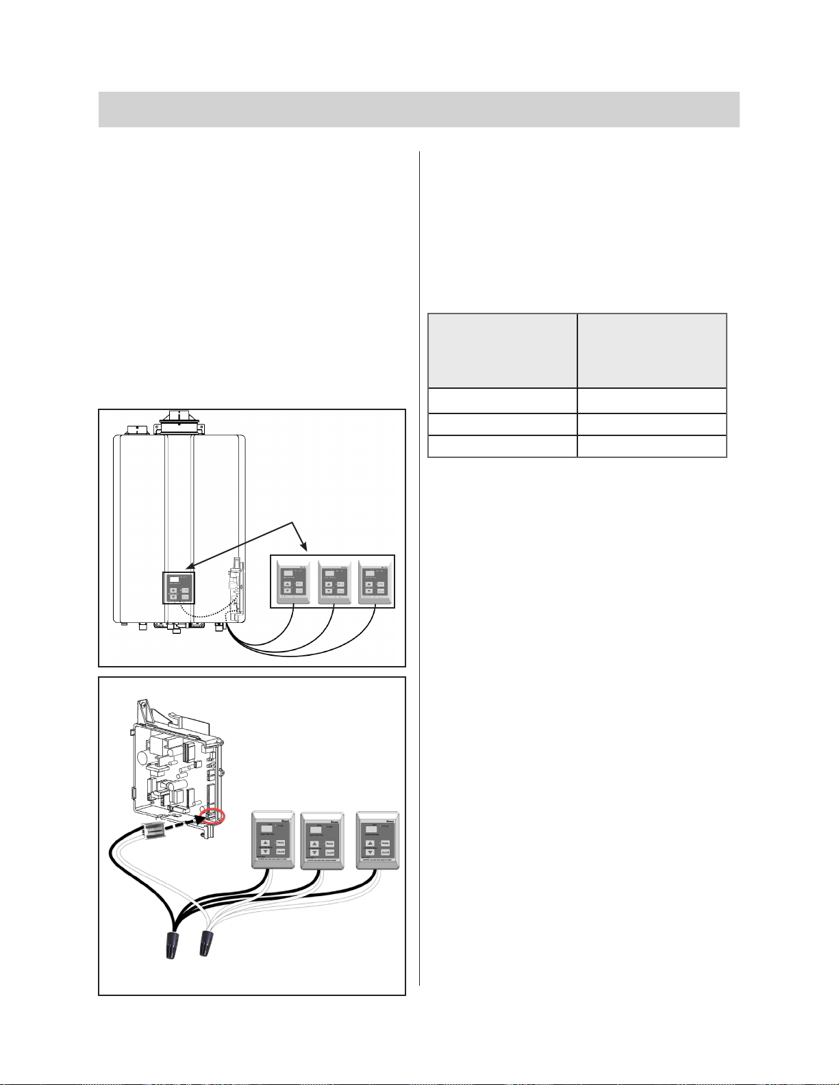
7.5 Guidelines for Additional Temperature Controllers
purchase).
Wiring
Cable Lengths and Sizes
Number of Wired
Controllers
Maximum Cable
Length for Each
Controller to Water
Heater
1
2
3 or 4 *
Controllers
Connect controller cable to
Wiring illustration
controller package)
Location
•
•
or radiant heater).
• -
sunlight.
• -
• -
public.
Figure 83
Figure 84
Table 34

Rinnai Tankless Water Heater Installation and Operation Manual 88
8. 8. WarrantyWarranty
What is Covered?
Residential Applications
15 Years
8 Years
5 Years 5 Years
Reasonable Labor 1 Year 1 Year
Notes:
What Will Rinnai Do?
during return shipping.
How To Obtain Service

Rinnai Tankless Water Heater Installation and Operation Manual 89
What Is Not Covered?
•
•
•
•
•
•
•
•
•
•
•
blockage)
• Incorrect sizing
•
•
•
•
•
Limitation on Warranties
state to state.

Rinnai Tankless Water Heater Installation and Operation Manual 90
NotesNotes

Rinnai Tankless Water Heater Installation and Operation Manual 91
NotesNotes

100000467(06)
6/2020
Rinnai America Corporation
103 International Drive
Peachtree City, GA 30269
Tel: 1-800-621-9419
Web: rinnai.us
rinnai.ca