
INSTALLATION MANUAL
www.kraususa.com I toll free: 1.800.775.0703 I © 2013-2014 Kraus USA Inc.
Single Lever Pull-Down
Kitchen Faucet
KPF-1630

Thank you for your purchase
We would like to take this opportunity to thank you for choosing Kraus. We hope
that you are completely satised with your purchase, and enjoy it for years to
come. If you have any questions, or require technical assistance, please contact us
at 800-775-0703 and one of our representatives will be happy to help.
For more information about Kraus products, please visit:
www.kraususa.com
In order to activate your warranty and receive the full benet of customer support,
please register your new Kraus product at:
www.kraususa.com/registration
Sincerely,
Kraus USA Customer Service

Prior to Installation:
• Make sure you have all necessary parts by checking the diagram and parts
list. If any part is missing or damaged, please contact Kraus Customer
Service at 800-775-0703 for a replacement
• Turn o the cold and hot water at the angle stops and turn on the old
faucet to release any built up pressure
• Flush angle stops to release any debris prior to installation
• Pre-drilled hole size requirement: 1-3/8” (min) – 1-1/2” (max)
• Max countertop thickness: 1-3/8

Diagram and Parts List
1
9
11
10
4A
3A
7
8A
2
5
6
12
8B
3B
4B
4C
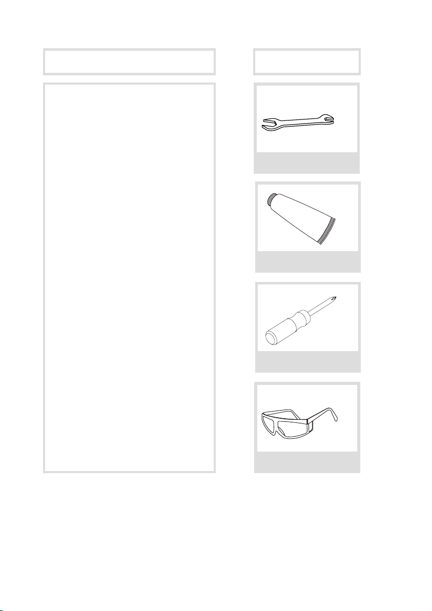
Diagram and Parts List
Tools you will need
1
10
279
10 31/32”
Minimum distance 90mm
Less than 90mm
Cold Water
32 3/32”
Ø35~Ø38
1
2
3
10
9
11
12
13
Hexagon Nut
Hot
Water
Cold
Water
2 3
1
4
5
7
6
8
4
5
6
7
8
Ø1 3/8”~
Ø1 1/2”
815
194
7 5/8”
Ø1 3/8~Ø1 1/2”
30˚
10
11
Close
Open
Left
Hot Water
Push
25˚
90˚
12
13
8
7
Ø35~Ø38
Max35
217
8 17/32”
Max1 3/8”
9
11
12
13
2
3
4
5
6
7
8
Adjustable Wrench
Phillips Screwdriver
Safety Goggles
Silicone Sealant
(optional)
1. Spray Head
2. Faucet Body
3. Deck Plate Assembly
A. Deck Plate
B. Base Plate
4. Mounting Hardware
A. Rubber & Metal Washer
B. Mounting Nut
C. Mounting Screws
5. Spray Hose
6. Weight
7. Check Valve
8. Hot and Cold Copper Lines
A. Cold
B. Hot
9. Aerator Key
10. Hex Wrench
11. Faucet Extender
12. Washer

Faucet Installation Procedure
Installer Tip:
Shut o main water supply before installing new faucet
9.2”
(233.8mm)
6.7”
(170.5mm)
2.87”
(73mm)
9.3”
(236mm)
5.35”
(136mm)
18.6”
(472.3mm)
4.9”
(125mm)
5
º
8.3”
(211.4mm)
3.95”
(100.5mm)
M33X1.5
9.2”
(233.8mm)
6.7”
(170.5mm)
2.87”
(73mm)
9.3”
(236mm)
5.35”
(136mm)
18.6”
(472.3mm)
4.9”
(125mm)
5
º
8.3”
(211.4mm)
3.95”
(100.5mm)
M33X1.5
Step 1: Remove mounting hardware
Remove the mounting
screws (4C), mounting nut
(4B), and rubber & metal
washer (4A) from the
mounting pipe
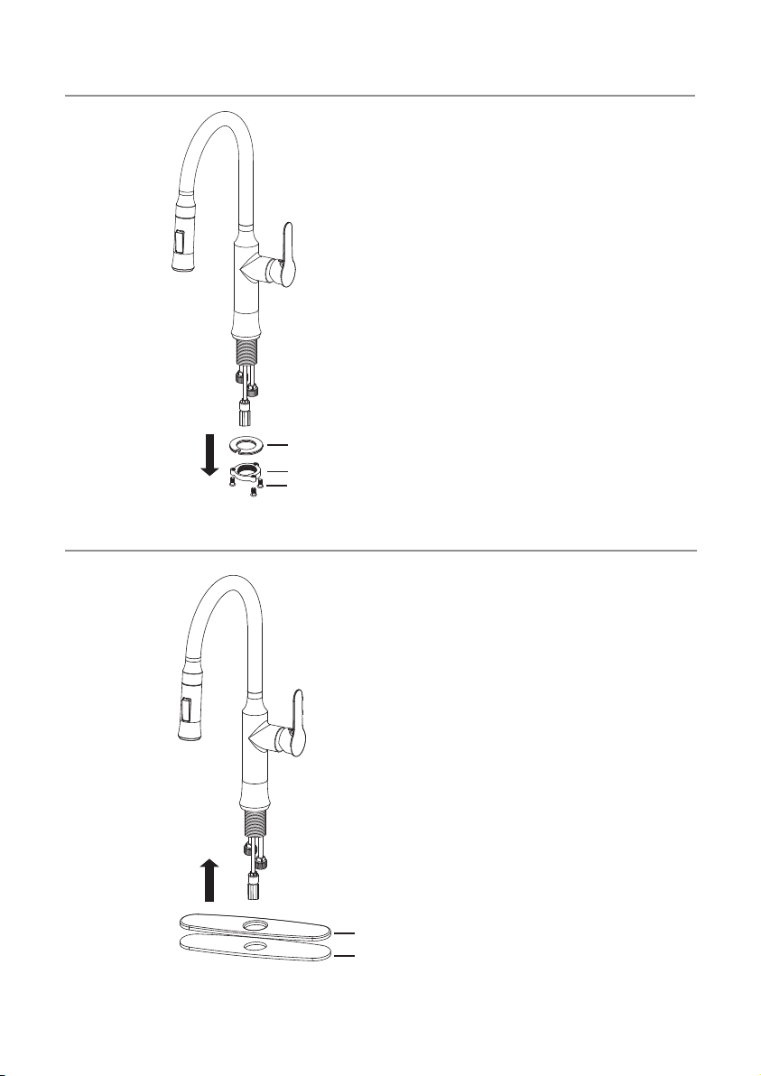
Step 2A: Faucet installation - with deck plate
For three-hole installation:
Deck plate (3A), base plate
(3B), and silicone sealant
(optional) are required
STEP1 STEP 2A STEP 2B STEP 3
STEP 4 STEP 5
STEP 6 STEP 7
STEP 8
4A
3A
3B
4B
4C
4B
4C
7
5
6
8
5
1
4A
4B
4C
STEP1 STEP 2A STEP 2B STEP 3
STEP 4 STEP 5
STEP 6 STEP 7
STEP 8
4A
3A
3B
4B
4C
4B
4C
7
5
6
8
5
1
4A
4B
4C

For single-hole installation:
Deck plate (3A), base plate
(3B), and silicone sealant
are NOT required
Step 3: Install faucet and mounting hardware
Insert faucet body (2) into
hole in countertop or deck
plate assembly (3). Install
mounting hardware (4A, B
&C) from underneath the
countertop
Step 2B: Faucet installation - without deck plate
STEP1 STEP 2A STEP 2B STEP 3
STEP 4 STEP 5
STEP 6 STEP 7
STEP 8
4A
3A
3B
4B
4C
4B
4C
7
5
6
8
5
1
4A
4B
4C
STEP1 STEP 2A STEP 2B STEP 3
STEP 4 STEP 5
STEP 6 STEP 7
STEP 8
4A
3A
3B
4B
4C
4B
4C
7
5
6
8
5
1
4A
4B
4C

Step 4: Secure mounting hardware
Adjust direction of faucet
body (2) so that handle is on
right side of faucet. Tighten
mounting nut (4B) until snug.
Tighten mounting screws
(4C) to nut with a Phillips
screwdriver until snug
Step 5: Attach spray hose and counterweight
Connect spray hose (5) to
check valve (7) attached to
supply line. Install weight
(6) on lowest vertical point
on spray hose (5)
STEP1 STEP 2A STEP 2B STEP 3
STEP 4 STEP 5
STEP 6 STEP 7
STEP 8
4A
3A
3B
4B
4C
4B
4C
7
5
6
8
5
1
4A
4B
4C
STEP1 STEP 2A STEP 2B STEP 3
STEP 4 STEP 5
STEP 6 STEP 7
STEP 8
4A
3A
3B
4B
4C
4B
4C
7
5
6
8
5
1
4A
4B
4C
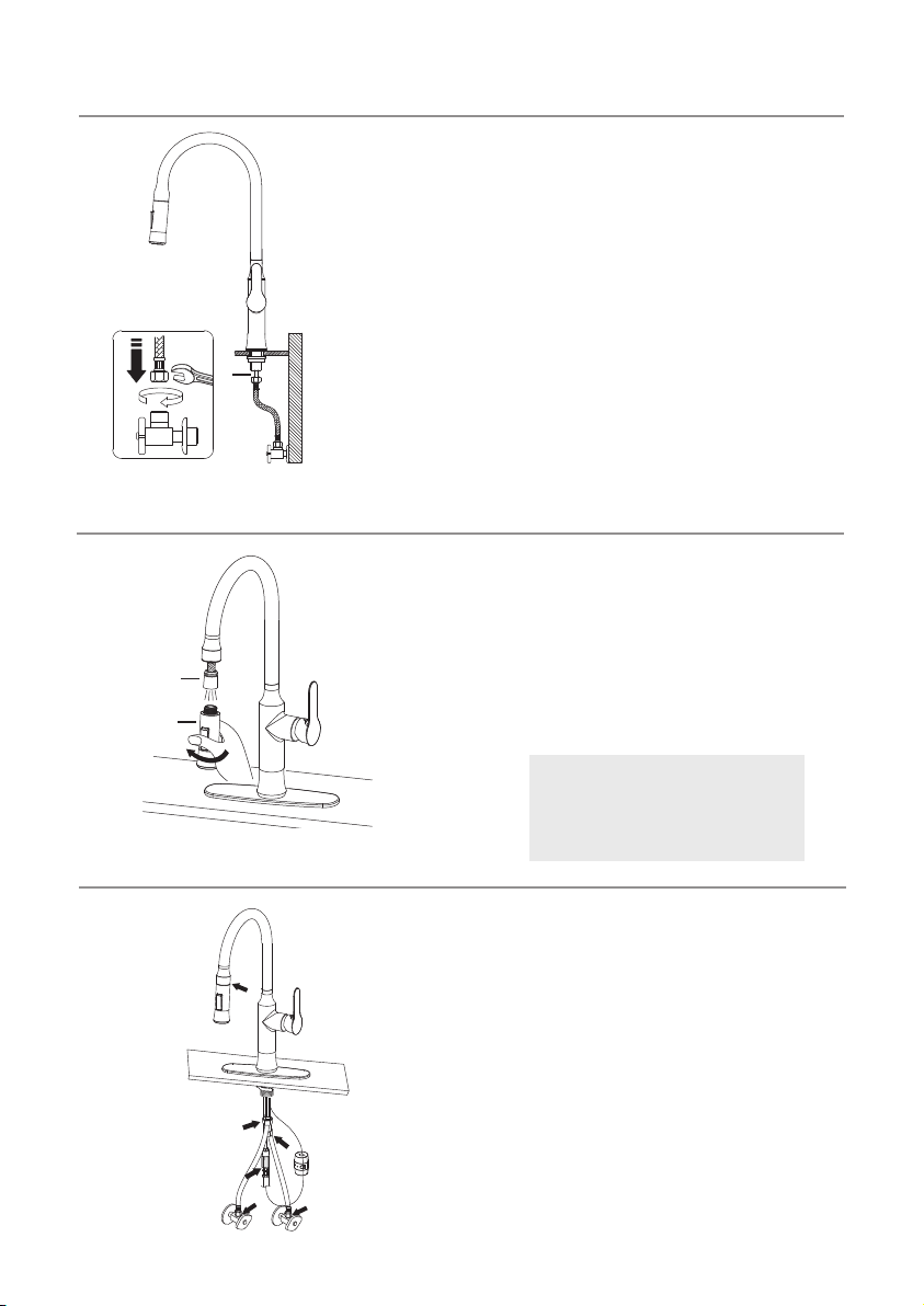
Connect waterlines (not
included) to hot and cold
copper lines (8). Connect
waterlines (not included) to
angle stops. Tighten both
ends of waterlines with a
wrench until snug. Turn on
hot and cold angle stops
and check for leaks
Step 7: Flush spray hose
Step 8 Check for leaks
Remove spray head (1) from
spray hose (5). Hold tip of
spray hose (5). Turn faucet on
and let the water run for 60
seconds to ush any debris
Check for leaks at the
connections. Retighten if
necessary
Step 6: Connect waterlines
STEP1 STEP 2A STEP 2B STEP 3
STEP 4 STEP 5
STEP 6 STEP 7
STEP 8
4A
3A
3B
4B
4C
4B
4C
7
5
6
8
5
1
4A
4B
4C
STEP1 STEP 2A STEP 2B STEP 3
STEP 4 STEP 5
STEP 6 STEP 7
STEP 8
4A
3A
3B
4B
4C
4B
4C
7
5
6
8
5
1
4A
4B
4C
STEP1 STEP 2A STEP 2B STEP 3
STEP 4 STEP 5
STEP 6 STEP 7
STEP 8
4A
3A
3B
4B
4C
4B
4C
7
5
6
8
5
1
4A
4B
4C
NOTE: Please make sure
washer (12) is installed
attaching spray head to hose
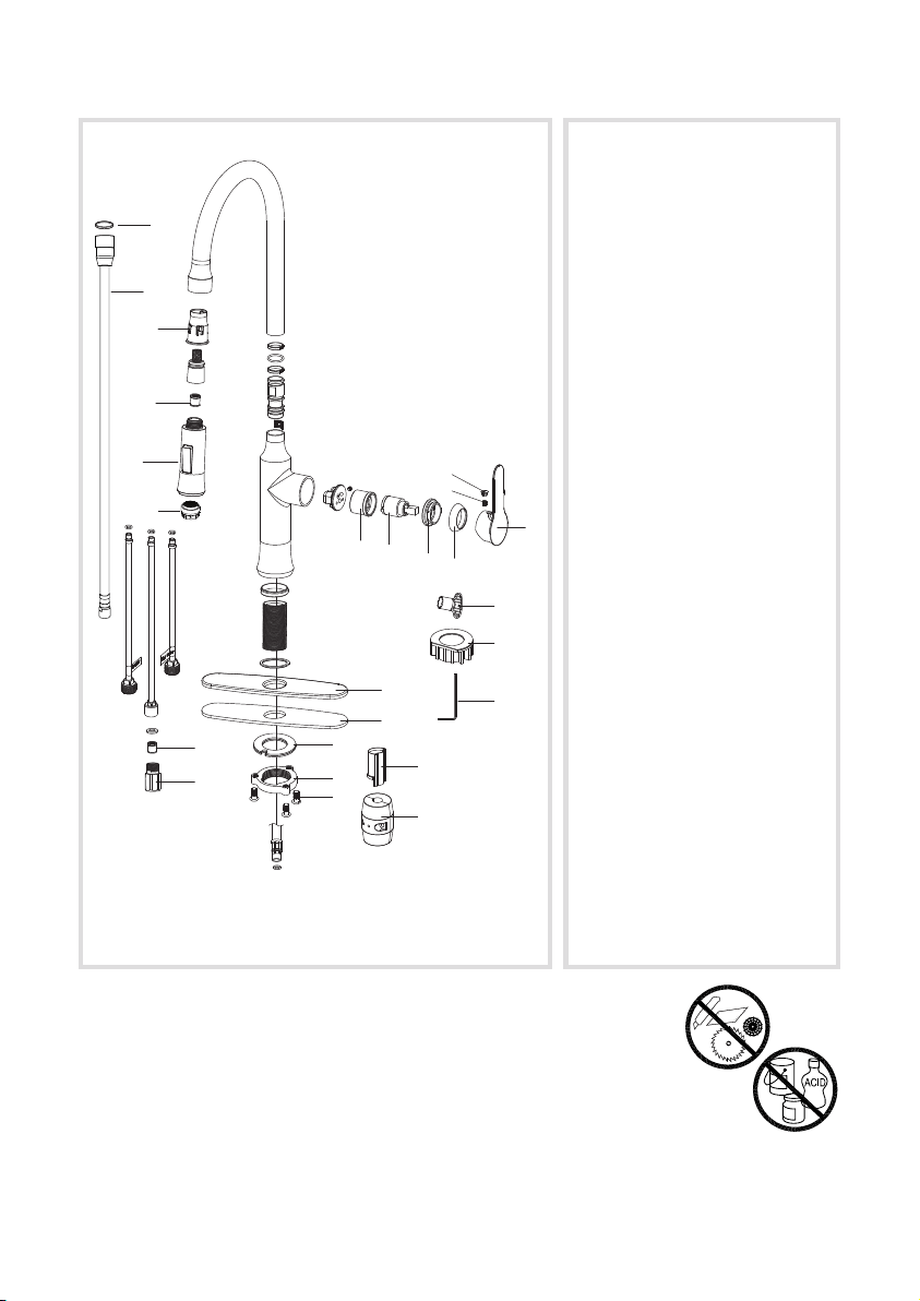
Care & Maintenance
*To keep the product clean & shining, follow the steps below:
1. Rinse with clean water & dry with a soft cloth
2. Do not clean with soaps, acid, polish, abrasives, or harsh cleaners
3. Do not use cloth with a coarse surface
4. Unscrew the aerator and clean when necessary
*This installation manual is subject to change without further notice.
1
10
279
10 31/32”
Minimum distance 90mm
Less than 90mm
Cold Water
32 3/32”
Ø35~Ø38
1
2
3
10
9
11
12
13
Hexagon Nut
Hot
Water
Cold
Water
2 3
1
4
5
7
6
8
4
5
6
7
8
Ø1 3/8”~
Ø1 1/2”
815
194
7 5/8”
Ø1 3/8~Ø1 1/2”
30˚
10
11
Close
Open
Left
Hot Water
Push
25˚
90˚
12
13
8
7
Ø35~Ø38
Max35
217
8 17/32”
Max1 3/8”
9
11
12
13
2
3
4
5
6
7
8
4
5
6
7
8
9
10
11
12
13
14
15
17
18
21
22
23
20
19
16
3
24
1B
2
1A
1. a. Aerator
b. Spray Head
2. Check Valve
3. Spray Hose
4. Hose Guide
5. Handle Button
6. Set Screw
7. Metal Handle
8. Cartridge Cover
9. Locking Nut
10. Cartridge
11. Cartridge Housing
12. Deck Plate
13. Base Plate
14. Rubber & Metal Washer
15. Mounting Nut
16. Mounting Screws
17. Protective Sleeve
18. Weight
19. Aerator Key
20. Faucet Extender
21. Hex Wrench
22. Check Valve
23. Connector
24. Washer
Replacement Parts

Trouble - Shooting
If you have followed the instructions carefully and your faucet still does not work
properly, take the following corrective steps:
PROBLEM CAUSE ACTION
Leakage under faucet
handle
Locking nut has come
loose or cartridge
needs to be reseated
Remove button located
at top of handle.
Loosen set screw with
hex wrench. Remove
handle and unscrew
cartridge cover by
hand. Tighten locking
nut with an adjustable
wrench
Leaking between spray
head and the hose
Spray head may be
loose or washer is not
seated correctly in the
hose connection
Tighten spray head by
hand until snug. Make
sure washer is seated
correctly
Hose does not retract Weight may be
installed incorrectly
Readjust weight on
hose
Low flow Aerator may be clogged Unscrew aerator with
aerator key. Hold tip of
spray head and turn on
water to flush debris
Water does not shut off
completely
Cartridge may need to
be adjusted or replaced
Remove button located
at top of handle.
Loosen set screw with
hex wrench. Remove
handle and unscrew
cartridge cover by
hand. Unscrew locking
nut with an adjustable
wrench. Remove
ceramic disc cartridge.
Check for cracks, and
if O-ring is seated
correctly. Reseat
cartridge

Step 1: Remove button
located at the top of the
handle. Loosen the set
screw with a hex wrench.
Remove the handle and
unscrew cartridge cover by
hand
Step 2: Unscrew the
locking nut with an
adjustable wrench. Remove
ceramic disc cartridge
Step 3: Place the new
cartridge in the handle
seat. Secure the cartridge
with the locking nut and
assemble the handle
Maintenance - Cartridge Replacement
STEP1 STEP 2A STEP 2B STEP 3
STEP 4 STEP 5
STEP 6 STEP 7
STEP 8
4A
3A
3B
4B
4C
4B
4C
7
5
6
8
5
1
4A
4B
4C
STEP1 STEP 2A STEP 2B STEP 3
STEP 4 STEP 5
STEP 6 STEP 7
STEP 8
4A
3A
3B
4B
4C
4B
4C
7
5
6
8
5
1
4A
4B
4C
STEP1 STEP 2A STEP 2B STEP 3
STEP 4 STEP 5
STEP 6 STEP 7
STEP 8
4A
3A
3B
4B
4C
4B
4C
7
5
6
8
5
1
4A
4B
4C

Codes/Standards Applicable:
KRAUS LIMITED LIFETIME WARRANTY
This product has been manufactured and tested to the highest quality standards
by Kraus USA Inc. (“Kraus”). We offer our customers thoughtfully crafted fixtures
& accessories, engineered for enduring performance over years of use.
WHO IS COVERED BY THE WARRANTY
This warranty extends to the original purchaser only. This warranty is not
transferable, between homes or owners and is only applicable to residential use.
WHAT IS COVERED BY THE WARRANTY
Kraus warranties this product against defects due to material or craftsmanship
error during the warranty period: Kraus will provide replacement parts at
no charge, or at its option, replace any product or part of the product that is
deemed defective, under normal installation, use, service and maintenance. If
Kraus is unable to provide a replacement and repair is not practical or cannot
be made in timely fashion, Kraus may elect to refund the purchase price in
exchange for the return of the product.
CONDITIONS AND EXCLUSIONS
Like other home fixtures, Kraus products will require light maintenance to
ensure proper function. We provide you with complete knowledge to perform
this maintenance and can also recommend resources if you are unable to fulfill
this service.
A. Kraus will not be responsible for product failures due to lack of maintenance
or proper use. Please read your care and maintenance documentation to deter-
mine the limits of proper use.
B. The original sales receipt, order number, and/or proof of purchase must be
presented at the time of the warranty claim, without exception, for this warranty
to be applied to all Kraus products.
Meets ASME A112.18.1M/A112.18.1
1.8gpm 6.8L/min maximum
GREEN
Water Eciency
LEAD FREE
I
A
P
M
O
R
&
T
TM
NSF/ANSI 61-9
NSF/ANSI 372

C. Kraus recommends installing all Kraus products with a licensed, professional
plumber. Kraus will not be held responsible for any damage or product failure
due to improper installation, misuse, or failure to use a licensed professional.
Please read your care and maintenance documentation to determine the limits
of proper use.
D. Commercial use will automatically void this warranty.
E. This warranty is not applicable to Kraus products purchased from an unau-
thorized seller. For a complete list of authorized sellers please visit http://www.
kraususa.com/where-to-buy.html
NONAPPLICABILITY OF THIS WARRANTY
By the purchase and use of our products, you agree that Kraus is not liable
for incidental, consequential or special damages associated with the return,
replacement, installation or use of your product. This includes freight costs,
cartridge replacement, labor, travel time, lost profit, home damages and other
contingent liabilities and costs (including, without limitation, costs associated
with experts, investigations, analyses, attorneys and other professionals and
services). The Kraus warranty is a comprehensive and explicit limit of liability,
and all items outside of it are not addressable by or the responsibility of
Kraus. Certain states have variances regarding implied warranties and in those
situations we remain fully compliant.
KRAUS USA Inc. makes no implication that products comply with any or all local
building or plumbing codes. It is the consumer’s responsibility to determine
local code compliance. This warranty extends to the original purchaser and first
consumer.
HELP LINE
For additional assistance at any point in the installation process, please call us at
1.800.775.0703 or email us at [email protected]
Our customer service hours are Monday – Friday, 9am – 8pm EST.
Be sure to visit our website at www.kraususa.com

www.kraususa.com