Loading ...
Loading ...
Loading ...
30
5 Human-machine interaction
5.1 LCD interface
Fig.5-1
Tab. 5-1: Introduction to symbols on the LCD panel
31
Human-machine interaction Human-machine interaction
SN Symbol Description
1
2
3
4
5
6
7
8
9
10
11
12
13
14
15
It alternately displays the DC voltage and current
It alternately displays the AC voltage and current
It means DC/AC connection
It means the on grid inverter
It means inverter enters into fault mode
It means communication mode of the inverter:
flicker means “connectied”, otherwise “disconnected”
It means the inverter is on ready mode.
It means the DC connection of the inverter is OK.
It means the inverter is working normally.
It means load rate of the inverter.
It indicates the current power.
It indicates the electric quantity of the current day.
It indicates the total electric quantity.
It indicates the current temperature of the inverter.
It indicates the amount of reducing CO2.
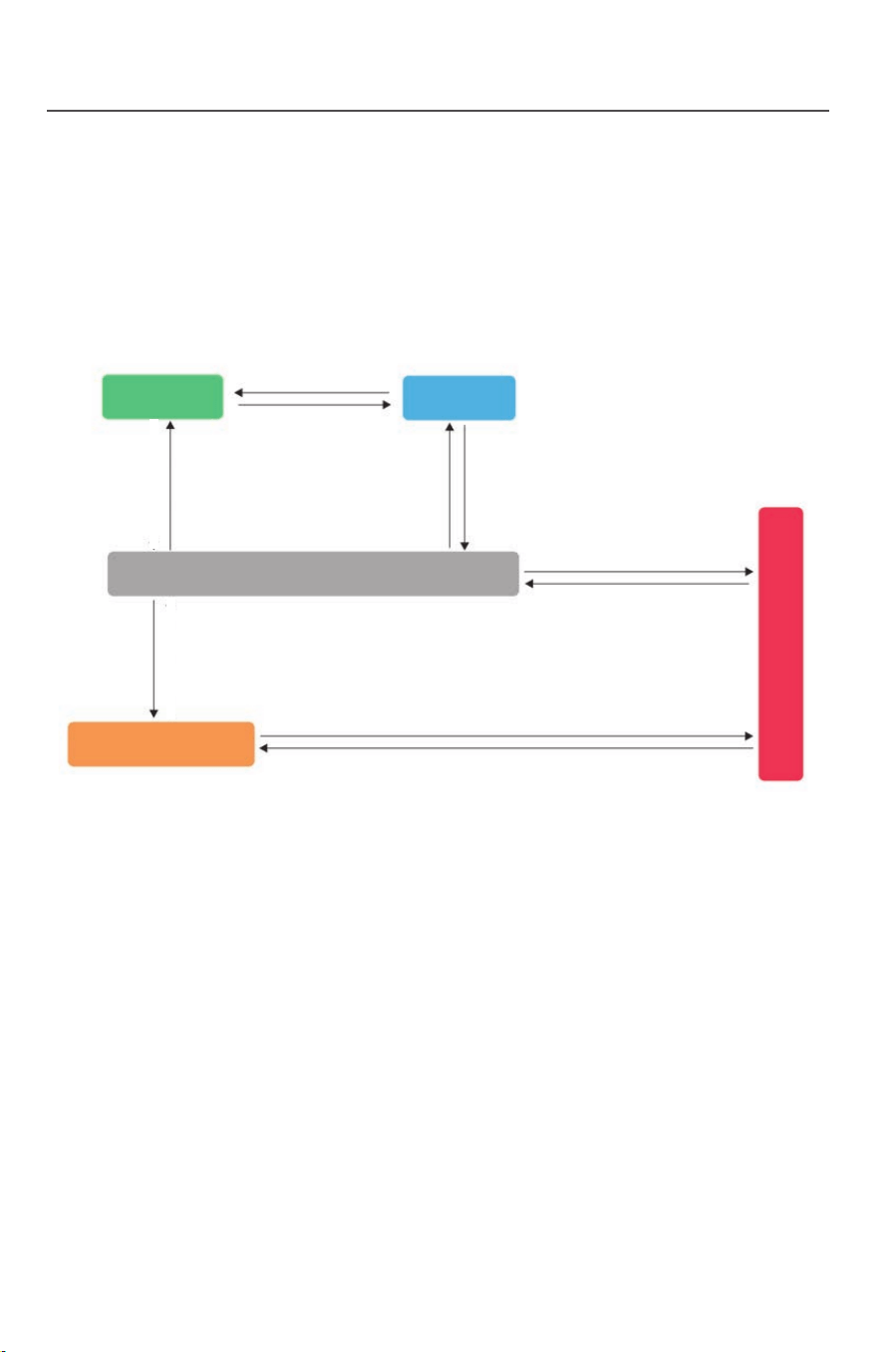
Fig. 5-2
Power off
Sleeping
DC
>300v
Td Waiting
Td=10-20S
Standing-by
Power generating
Device fault/environmental abnormity
Fault/protection recovery Th self-detecting
Th=60-70S
Fault/Protection
Device fault/environmental
abnormity
Fault/protection
recovery
Th=self-detect
Th=60-70S
5.2 Inverter working mode
After the inverter is started up, the normal working state will be
switched as per
the chart below:
DC<250v
DC>250v
DC<250v
DC<300v DC>300v
Loading ...
Loading ...
Loading ...