Negro
Verde
Rojo
Rojo
Blanco
Etiquete
Negro
Negro
Verde
Blanco
Ranura
Terminales
de tornillo
Wallplate
Dimmer
Incandescent/Dimmable CFL/
Dimmable LED 120VAC Dimmer
Rated at 120VAC, 60Hz; 600 Watts MAX Incandescent,
150 Watts MAX dimmable LED, 150 Watts MAX
dimmable CFL
RISK OF ELECTRIC SHOCK
•
SHUT OFF POWER AT FUSE BOX OR CIRCUIT BREAKER
BEFORE INSTALLATION
RISK OF FIRE
•
DO NOT USE TO CONTROL RECEPTACLE OUTLETS,
FLUORESCENT LIGHTING FIXTURES, MOTOR-OPERATED
APPLIANCES OR TRANSFORMER-SUPPLIED
APPLIANCES
•
DO NOT EXCEED ELECTRICAL RATINGS
•
USE COPPER WIRE ONLY WITH THIS DEVICE
•
USE INDOORS ONLY
WARNING
1-year Limited Warranty: Jasco Products Company warrants
this product to be free from manufacturing defects for a period
of one year from the original date of consumer purchase. This
warranty is limited to the repair or replacement of this product
only and does not extend to consequential or incidental damage
to other products that may be used with this unit. This warranty
is in lieu of all other warranties express or implied. Some states
do not allow limitations on how long an implied warranty lasts or
permit the exclusion or limitation of incidental or consequential
damages, so the above limitations may not apply to you. This
warranty gives you specific rights, and you may also have other
rights which vary from state to state. If unit should prove
defective within the warranty period, return prepaid with dated
proof of purchase to: Jasco Products Company, 10 E. Memorial
Rd., Oklahoma City, OK 73114.
Dimmer Instr
CFL_LED_All
8.5” x 11.5”
2-sided print,
Black
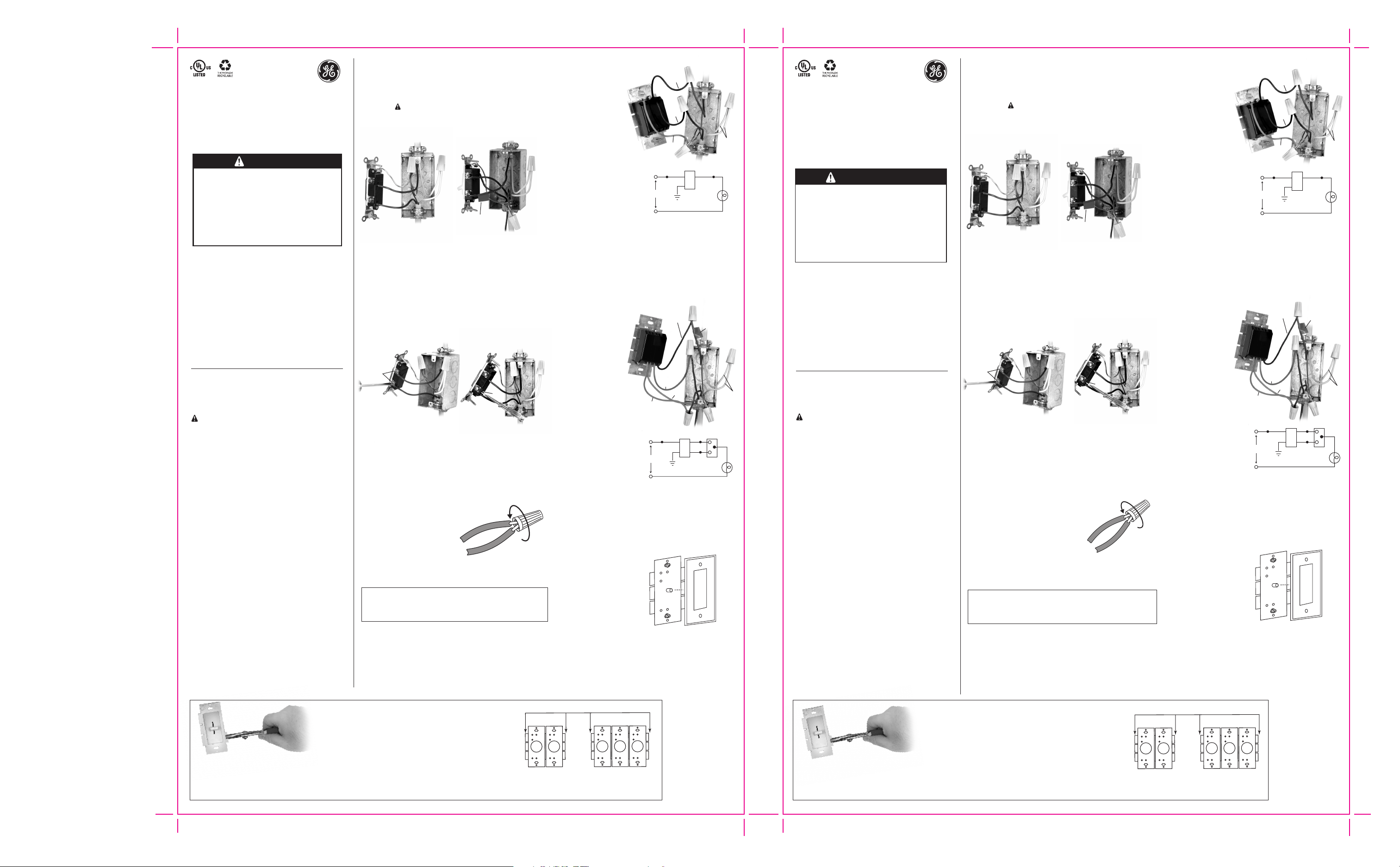
Directions for multiple gang installations
If you choose to install multiple dimmers in the same switch box, you may need
to remove the inside tabs on the dimmers before continuing with the wiring
installation (see illustration). If there is a dimmer already in the switch box, make
sure the power is OFF at the circuit breaker or fuse box, then remove the
wallplate. Taking care not to damage the dimmer, use a tool such as pliers to
grasp the tabs and move back and forth until they snap off at the break line. Only
do this for each row of tabs that need removal so the dimmers fit side by side in
the switch box. The removal of tabs and ganging the dimmers reduces the
maximum load capacity of the dimmers. For maximum dimmer load ratings
while with and without ganging, see our note.
Dimmer Capacity
Single : 600W incandescent, 150W CFL or LED
2 gang : 500W incandescent, 125W CFL or LED
3 gang or more : 400W Incandescent, 100W CFL or LED
Do NOT Remove Outside Tabs
2 Gang 3 Gang
Both dimmers have inside
tabs removed
Inside dimmer has both
side tabs removed while outside
dimmers have only the inside
tabs removed
How to install your dimmer
A. Ensure to turn off power to the switch box by flipping OFF
the correct circuit breaker or removing the correct fuse.
B. Take off the wallplate and remove switch mounting
screws. Warning: Verify power is OFF to switch box
before continuing. Carefully remove switch from switch
box but DO NOT disconnect the wires.
C. Determine the type of circuit:
Disconnect wires from the switch
D. Take care when disconnecting wires from the switch.
Observe important wiring information
Always follow the recommended wire strip lengths and
wiring combinations when making wiring connections.
Important: The wire connectors included with this dimmer
are intended to only be used with copper wire. Consult a
qualified electrician if you have aluminum wiring.
Instructions:
1. Strip insulation 3/8” for 12 or
14 AWG wire. Strip insulation
7/16” for 16 or 18 AWG wire.
2. Hold stripped ends together in
parallel and align any frayed strands (do not twist wires).
3. Push wires firmly into connector. Twist connector clockwise
with fingers until tight. Pull wires to check for tightness.
How to wire your new dimmer
E. If you choose to install more than one dimmer in the same
switch box, remember to review the instructions for
multiple-gang installations before continuing.
Important: Our dimmers can have different wire locations so
ensure to identify the wires by color and not by location.
E-1. Wiring a single-pole dimmer
There are three wires (2 black
and 1 green) exiting the
back of the dimmer
casing.
1. Connect the green
dimmer ground wire to
the green or bare
copper ground wire in
the switch box.
2. Choose either of the black
dimmer wires and connect
to either of the wires previously
removed from the switch.
3. With only one black wire
remaining from the dimmer,
connect this wire to the
remaining wire previously
removed from the switch.
Important: It is acceptable to use a 3-way dimmer in
single-pole application. Simply use a wire connecter to cap
off one of the red wires exiting from the back of the dimmer.
Then follow the single dimmer wiring directions substituting
the remaining red wire for one of the black wires. (You will
need to switch the position of the red wires if the on/off
switch works opposite of the desired operation.)
E-2. Wiring a 3-way dimmer
Important: Only one 3-way dimmer can be
used in a 3-way circuit.
There are four wires (2 red,
1 black and 1 green)
exiting
the back of the
dimmer casing.
1. Connect the green
dimmer ground wire
to the green or bare
copper ground
wire in the switch box.
2. Identify the tagged or
marked wire removed from
the different colored switch
screw labeled COMMON or COM.
Connect this wire to the only
black wire on the dimmer.
3. Choose either of the red
dimmer wires and connect
to either of the wires
previously removed from
the switch.
4. With only one red wire remaining from the dimmer,
connect this wire to the remaining wire previously
removed from the switch.
Now, you may remove the tag from wire exiting the switch box.
Insert the dimmer inside the switch box
F. You are now ready to
complete your dimmer
installation. Position all wires
inside the switch box with
care leaving enough room
in the switch box to insert
the dimmer housing. Use the
mounting screws provided
with your dimmer to mount
the dimmer securely inside
the switch box. You can now
replace the wallplate over your new dimmer. If you are
installing a rotary-style dimmer, remove the round knob
from the face of the dimmer. Now, you can install a toggle-
style wallplate over the stem of the dimmer. Firmly press
the knob back on to complete your installation.
G. Restore power by flipping the circuit breaker back to ON or
replacing the fuse.
Screw terminals:
Turn and loosen screws,
then remove wires.
Push terminals:
Insert small screwdriver
into slot and pull wires out.
Wire Connector/Combination Chart
(1)#14 w/ (1) to (4)#16 or #18
(2)#14 w/ (1) to (3)#16 or #18
(1)#12 w/ (1) to (3)#14 or #16 or #18
(2)#12 w/ (1) or (2)#14 or #16 or #18
BlackBlack
Ground
Light
Dimmer
Green
120VAC
60Hz
Vital information –
Read instructions before
beginning installation
WARNING: Use only with permanently-installed
120VAC fixtures. To avoid overheating and
possible damage to other equipment, do not use
to control receptacles, fluorescent lighting
fixtures, motor-driven appliances or
transformer-supplied appliances.
• Always use appropriate electrical power
verification instruments to verify power is OFF
before installing dimmer.
• Always install your dimmer in accordance with all
national and local electrical codes.
• Install a test switch and verify correct lighting
operation before installing the dimmer on all
new installations.
• If no grounding means exist within the switch box,
you must use the provided wire connector to cap
the green ground wire. A dimmer installed in this
manner must be installed with a plastic, UL-listed
wallplate and plastic screws.
• Only one 3-way dimmer can be used in a
3-way circuit.
• 40 Watts incandescent or equivalent dimmable
LED/CFL is the recommended minimum load for
this dimmer.
• Shield dimmer from dust and dirt during spackling
or painting.
• To clean dimmer, use a soft, water-dampened
cloth only. Do not use any chemical cleaners.
• During normal dimmer operation, the dimmer
may feel warm to the touch.
Single-pole:
Will have two insulated
wires connected to two
screws of the same color.
Replace the switch with a
SINGLE-POLE dimmer. You
will use Step E-1
instructions for installation.
3-Way:
Will have three insulated wires
connected to three screws. One of these
wires is connected to a screw of a
different color (not green) which is
labeled COMMON or COM. Remember to
TAG or MARK this wire so it can be
identified while wiring the new 3-way
dimmer. Replace the switch with a
3-way dimmer. You will use Step E-2
instructions for installation.
Screw
Terminals
Slot
Black
Black
Tag
Tag
Green
White
Black
Green
Red
Red
White
Atenuador de luz Incandescente/
Dimmable CFL / Dimmable LED
de 120VAC
Rendimiento: 120VAC, 60Hz; 600 Watts MAX
Incandescent, 150 Watts MAX LED regulable, 150
Watts MAX CFL regulable
Instrucciones para Instalaciones Múltiples
Si quiere instalar varios atenuadores en la misma caja del interruptor, antes de continuar
con la instalación, quizá tenga que quitar las lengüetas internas de los atenuadores. Vea
la ilustración. Si hay otro atenuador en la caja del interruptor, corte la corriente con el
interruptor general o con el fusible, y saque la placa de pared. Con cuidado para no dañar
el atenuador, use un alicate o una herramienta similar, y doble las lengüetas hacia
adelante y hacia atrás hasta que se partan por el vértice. Solo haga esto con las hileras de
lengüetas que tiene que sacar para que el atenuador entre completamente dentro de la
caja del interruptor. La extracción de las lengüetas y de las conexiones múltiples del
atenuador reduce la capacidad de carga máxima. Vea nuestra nota para obtener el
rango máximo de carga para los atenuadores con conexiones múltiples o simples.
Cómo instalar sus atenuadores
A. Asegúrese de cortar la corriente de la caja de fusibles;
puede bajar el interruptor o sacar el fusible correspondiente.
B. Saque la placa de pared y retire los tornillos que sujetan el
interruptor. ADVERTENCIA: Antes de continuar,
asegúrese DE QUE NO HAYA FLUJO DE ELECTRICIDAD
hacia el interruptor. Con cuidado, saque el interruptor de la
caja del interruptor pero NO saque los cables.
C. Determine el tipo de circuito:
Desconecte los cables del interruptor
D. Tenga cuidado cuando desconecte los cables del
interruptor.
Información importante sobre el cableado
Cuando conecte los cables, mantenga las combinaciones y el
largo de los cables desnudos que se recomiendan para los
conectores de los cables incluidos. Importante: Los conectores
de los cables incluidos se deben usar sólo con cables de cobre.
Para cables de aluminio, consulte a un electricista.
Instrucciones:
a. Quite 3/8” del revestimiento para cables de 12 AWG
o 14 AWG. Quite 7/16” del revestimiento para cables
de 16 AWG o 18 AWG.
b. Una de forma paralela los extremos pelados y
alinee los filamentos deshilachados (no enrosque
los cables).
c. Jale firmemente los cables hacia el conector. Con los dedos, enrosque el
conector en sentido de las agujas del reloj hasta que estén ajustados. Jale
los cables para asegurarse que estén ajustados.
Cómo conectar su nuevo atenuador de luz?
E. Si va a instalar más de un atenuador en la misma caja del
interruptor, antes de continuar no se olvide de consultar
las instrucciones sobre Instalaciones Múltiples.
Importante: Los cables de nuestros atenuadores pueden
estar en diferentes lugares; por eso, tiene que identificar los
cables por su color, no su ubicación.
E-1. Instalación de un atenuador unipolar
En la parte de atrás de la caja del
atenuador, sobresalen tres
cables (2 negros y 1 verde).
1. Conecte el cable a
tierra verde del
atenuador al cable de
tierra verde o pelado de
la caja del interruptor.
2. Escoja cualquiera de los
cables negros del atenuador
y conéctelos a cualquiera de
los cables que ha sacado
del interruptor.
3. Conecte el cable negro que
queda del atenuador al cable
restante que previamente ha
sacado del interruptor.
Importante: Se puede usar un atenuador trifásico en una
aplicación unipolar. Simplemente use un conector de cable para
aislar uno de los cables rojos que salen de la parte de atrás del
atenuador. Luego siga las indicaciones para instalar el atenuador
unipolar. (Si el interruptor de encendido/apagado funciona de
forma inversa, tendrá que intercambiar los cables rojos).
E-2. Instalación de un atenuador trifásico
Importante: En un circuito trifásico sólo se puede usar un
atenuador trifásico. En la parte de atrás de la caja del
atenuador, sobresalen cuatro cables (2 rojos,
1 negro y 1 verde).
1. Conecte el cable a tierra
verde del atenuador al
cable de tierra verde o
pelado de la caja del
interruptor.
2. Ubique el cable
ETIQUETADO o MARCADO
que ha sacado del tornillo de
diferentes colores del interruptor;
el tornillo tendrá el nombre
COMMON o COM. Conecte este
cable al único cable negro
del atenuador.
3. Escoja cualquiera de los
cables rojos del atenuador
y conéctelo a cualquiera de
los cables que previamente
ha sacado del interruptor.
4. Conecte el cable rojo que queda del atenuador al cable
restante que previamente ha sacado del interruptor.
Ahora tendrá que sacar la etiqueta del cable que sale de la
caja del interruptor.
Inserte el atenuador dentro de la caja
del interruptor
F.
Ahora ya puede terminar de instalar del atenuador.
Con cuidado coloque todos los
cables dentro de la caja del
interruptor; deje suficiente
espacio dentro de la caja para
introducir el compartimiento
del atenuador. Use los tornillos
de montaje incluidos con su
atenuador para asegurar el
atenuador dentro de la caja
del interruptor. Ya puede volver
a colocar la placa de pared sobre el nuevo atenuador.
Si está instalando un atenuador con control giratorio,
extraiga la perilla redonda de la parte frontal del atenuador.
Ahora ya puede colocar una placa de pared tipo palanca
sobre la barra del atenuador. Vuelva a poner la perilla y
presione firmemente para completar la instalación.
G. Suba el interruptor general o vuelva a colocar el fusible
para volver a conectar la electricidad.
Terminales de tornillo:
Gire los tornillos para
aflojarlos.
Terminales de empuje:
Inserte el destornillador.
Jale el cable hacia fuera.
Información vital -
el leyó instrucciones antes de
comenzar la instalación
ADVERTENCIA: Úsese sólo con dispositivos de 120V
CA instalados permanentemente. Para evitar el
sobrecalentamiento y posible daño a otros equipos,
no lo use para controlar enchufes, dispositivos
fluorescentes o aparatos operados a motor o que
usen transformadores.
• Siempre use los instrumentos adecuados para
verificar la energía eléctrica; asegúrese de haber
cortado la electricidad.
• Tiene que instalar el atenuador de luz de acuerdo
a las normas nacionales y locales para
dispositivos eléctricos.
• Antes de instalar todos los atenuadores, instale un
interruptor de prueba y establezca el
funcionamiento correcto del atenuador de luz.
• Si las paredes de la caja no tienen una conexión a
tierra, use el conector de cable incluido para aislar
el cable de tierra verde. Si el atenuador se instala
de esta manera, se deberá instalar con una placa
de pared de plástico con certificación UL y
tornillos de plástico.
• En un circuito trifásico sólo se puede usar un
atenuador trifásico.
• 40 Vatios incandescente o equivalente regulable
LED / CFL es la carga mínima recomendada para
este potenciómetro.
• Cuando vaya a aplicar pintura o masilla, proteja el
atenuador de polvo y suciedad.
• Para limpiar el atenuador, use sólo un paño suave
humedecido. No use limpiadores químicos.
• Cuando esté funcionando normalmente, es
común que se sienta caliente al tacto.
Unipolar:
Cables aislados
conectados a dos
tornillos del mismo color.
Sustitúyalo con un
atenuador UNIPOLAR.
Usted utilizará las
instrucciones E-1 para la
instalación.
Trifásico:
3 Cables aislados conectados a tres
tornillos. Uno de estos cables está
conectado a un tornillo de diferente
color (no verde) o muestra el nombre
COMMON o COM. MARQUE o ETIQUETE
el cable para identificarlo cuando realice
el cableado. Sustitúyalo con un
atenuador TRIFÁSICO. Usted utilizará las
instrucciones E-1 para la instalación.
RIESGO DE CHOQUE ELÉCTRICO
• ANTES DE INSTALAR, CORTE LA ELECTRICIDAD DESDE LA CAJA
DE FUSIBLES O CON EL INTERRUPTOR DE LUZ.
RIESGO DE INCENDIO
• NO LO USE PARA CONTROLAR TOMACORRIENTES,
DISPOSITIVOS FLUORESCENTES O ELECTRODOMÉSTICOS QUE
USEN MOTOR O TRANSFORMADORES.
• NO EXCEDA EL RENDIMIENTO ELÉCTRICO PERMITIDO.
• PARA ESTE ARTEFACTO, USE SÓLO CABLES DE COBRE.
• ÚSESE SOLAMENTE EN INTERIORES.
ADVERTENCIA
1 Año de garantía limitada: La Compañía Jasco Products garantiza
por un periodo de un año desde la fecha original de la compra, que
este producto no presenta ningún defecto de fábrica. Esta garantía
está limitada sólo a la reparación o reemplazo del producto y no se
extiende al daño resultante o incidental de otros productos que se
han sido usados con esta unidad. Esta garantía remplaza a cualquier
otra garantía expresa o implícita. Algunos estados no reconocen
límites de tiempo en las garantías implícitas y tampoco permiten la
exclusión o limitación de daños incidentales o resultantes; por lo tanto,
las limitaciones mencionadas pueden no ser aplicables en su caso.
Esta garantía le proporciona derechos específicos; pero dependiendo
del estado, también puede tener otros derechos. Si la unidad presenta
algún defecto dentro del periodo de garantía, devuélvala junto con el
costo del envío y la prueba de compra, a: Jasco Products Company,
10 E. Memorial Rd., Oklahoma City, OK 73114.
No quite las secciones exteriores
2 conexiones 3 conexiones
Se han sacado secciones
interiores en todos
los controles.
Se han sacado dos secciones
laterales del control
del medio.
Capacidad del atenuador
Rendimiento del atenuador: 600W
Individual : 600W incandescente, 150W CFL o LED
2 conexiones : 500W incandescente, 125W CFL o LED
3 conexiones o más : 400W incandescente, 100W CFL o LED
Placa de pared
Atenuador
Conector de cable/Tabla de combinaciones
Etiquete
Negro Negro
a Tierra
Luz
Atenuador
Verde
120VAC
60Hz
Rojo
Rojo
Negro
a Tierra
Luz
Atenuador Interruptor
trifásico
Verde
120VAC
60Hz
side 1 - English side 2 - Spanish
(1)#14 w/ (1) to (4)#16 or #18
(2)#14 w/ (1) to (3)#16 or #18
(1)#12 w/ (1) to (3)#14 or #16 or #18
(2)#12 w/ (1) or (2)#14 or #16 or #18
10464 V3 • 5/23/18
MADE IN CHINA
GE is a trademark of General
Electric Company and is under
license by Jasco Products
Company LLC, 10 E. Memorial
Rd., Oklahoma City, OK 73114.
This Jasco product comes with
a 1-year limited warranty.
Visit www.byjasco.com for
warranty details.
Questions? Contact us at
1-800-654-8483
between 7:00AM—8:00PM CST.
HECHO EN CHINA
GE es una marca comercial de
General Electric Company con
licencia otorgada a Jasco
Products Company LLC,
10 E. Memorial Rd., Oklahoma
City, OK 73114.
Este producto de Jasco tiene
una garantía limitada de 1 año.
Visite www.byjasco.com para
conocer los detalles de la
garantía.
¿Preguntas? Comuníquese al
1-800-654-8483 entre las 7:00
a. m. y las 8:00 p. m. CST (hora
central estándar).
Red
Red
Black
Ground
Light
Dimmer 3-Way Switch
Green
120VAC
60Hz