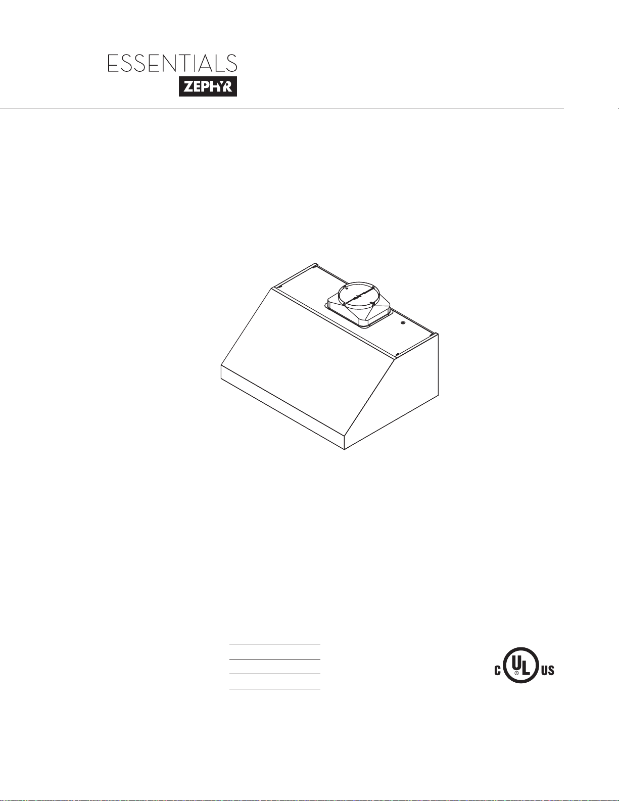
Use, Care, and Installation Guide
www.zephyronline.com
Model number:
Serial Number:
Date of Purchase:
Sales Dealer:
DEC15.0101 © 2015 Zephyr Ventilation LLC.
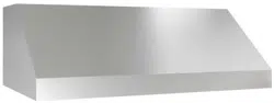
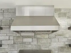
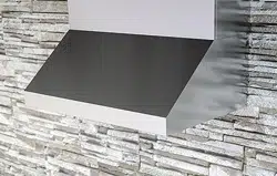
Cypress
AK7836BS
AK7842BS
AK7848BS
AK7854BS
READ AND SAVE THESE INSTRUCTIONS
INTENDED FOR OUTDOOR COVERED PATIO OR LANAI AREA.

www.zephyronline.com

1
SAFETY NOTICE ................................................................. 2-3
LIST OF MATERIALS ....................................................... 4
INSTALLATION
Ducting Calculation Sheet
....................................... 5
Mounting Height & Clearance
................................ 6
Ducting Options
........................................................... 7
6SHFL¿FDWLRQV
............................................................... 8
Electrical
......................................................................... 9
Mounting the Range Hood
...................................... 10
Horizontal Ducting Conversion
.............................. 11
FEATURES & CONTROLS
Rotary Controls
............................................................ 12
MAINTENANCE
Cleaning and Filter Removal
.................................. 13
Lights
................................................................................ 14
TROUBLESHOOTING
................................................................ 15
WIRING DIAGRAMS
................................................................... 16
FAN CURVE DIAGRAMS
......................................................... 17
LIST OF PARTS AND ACCESSORIES
.............................. 18
WARRANTY
.................................................................................... 19
PRODUCT REGISTRATION
.................................................... 20
Table of Contents

Important Safety Notice
READ AND SAVE THESE INSTRUCTIONS
2
www.zephyronline.com
WARNING
TO REDUCE THE RISK OF FIRE OR ELECTRIC SHOCK, DO NOT USE THIS FAN WITH ANY SOLID-STATE CONTROL DEVICE.
WARNING
TO REDUCE THE RISK OF FIRE ELECTRIC SHOCK, OR INJURY TO PERSONS, OBSERVE THE FOLLOWING:
a. Use this unit only in the manner intended by the manufacturer, if you have questions, contact the manufacturer.
b. Before servicing or cleaning unit, switch power off at service panel and lock panel to prevent power from being switched on accidentally.
When the service disconnecting means cannot be locked, securely fasten a prominent warning device, such as a tag, to the service
panel.
c. This unit must be grounded and protected by a GFCI.
d. Suitable for use in damp locations only when installed in a GFCI PROTECTED branch-circuit.
CAUTION
For general ventilating use only. Do not use to exhaust hazardous or explosive materials and vapors. Take care when using cleaning
agents or detergents. Suitable for use in household cooking area.
WARNING
TO REDUCE THE RISK OF RANGE TOP GREASE FIRE:
a. Never leave surface units unattended at high settings. Boilovers cause smoking and greasy spillovers that may ignite. Heat oils slowly
on low or medium settings.
E $OZD\VWXUQKRRG21ZKHQFRRNLQJDWKLJKKHDWRUZKHQÀDPLQJIRRG
F &OHDQYHQWLODWLQJIDQVIUHTXHQWO\*UHDVHVKRXOGQRWEHDOORZHGWRDFFXPXODWHRQIDQRU¿OWHU
d. Use proper pan size. Always use cookware appropriate for the size of the surface element.
H .HHSIDQ¿OWHUVDQGJUHDVHODGHQVXUIDFHVFOHDQ
f. Use high setting on hood only when necessary.
g. Don’t leave hood unattended when cooking.
h. Always use cookware and utensils appropriate for the type of and amount of food being prepared.
WARNING
TO REDUCE THE RISK OF INJURY TO PERSONS IN THE EVENT OF A RANGE TOP FIRE, OBSERVE THE FOLLOWING:
D 6027+(5)/$0(6ZLWKDFORVH¿WWLQJOLGFRRNLHVKHHWRUPHWDOWUD\WKHQWXUQRIIWKHEXUQHU%(&$5()8/7235(9(17%8516
,IWKHÀDPHVGRQRWJRRXWLPPHGLDWHO\(9$&8$7($1'&$//7+(),5('(3$570(17
b. NEVER PICK UP A FLAMING PAN – You may be burned.
c. DO NOT USE WATER, including wet dishcloths or towels – a violent steam explosion will result.
d. Use an extinguisher ONLY if:
1. You know you have a Class ABC extinguisher, and you already know how to operate it.
7KH¿UHLVVPDOODQGFRQWDLQHGLQWKHDUHDZKHUHLWVWDUWHG
7KH¿UHGHSDUWPHQWLVEHLQJFDOOHG
<RXFDQ¿JKWWKH¿UHZLWK\RXUEDFNWRDQH[LW
WARNING
TO REDUCE THE RISK OF FIRE, ELECTRIC SHOCK OR INJURY TO PERSONS, OBSERVE THE FOLLOWING:
D ,QVWDOODWLRQZRUNDQGHOHFWULFDOZLULQJPXVWEHGRQHE\TXDOL¿HGSHUVRQVLQDFFRUGDQFHZLWKDOODSSOLFDEOHFRGHVDQGVWDQGDUGV
,QFOXGLQJ¿UHUDWHGFRQVWUXFWLRQ
E 6XI¿FLHQWDLULVQHHGHGIRUSRZHUFRPEXVWLRQDQGH[KDXVWLQJRIJDVHVWKURXJKWKHÀXHFKLPQH\RIIXHOEXUQLQJHTXLSPHQWWRSUHYHQW
back-drafting. Follow the heating equipment manufacturer’s guideline and safety standards such as those published by the National
)LUH3URWHFWLRQ$VVRFLDWLRQ1)3$DQGWKH$PHULFDQ6RFLHW\IRU+HDWLQJ5HIULJHUDWLRQDQG$LU&RQGLWLRQLQJ(QJLQHHUV$6+5$(DQG
the local code authorities.
c. When cutting or drilling into wall or ceiling, do not damage electrical wiring and other hidden utilities.
d. Ducted fans must always vent to the outdoors.
e. NEVER place a switch where it can be reached from a tub or shower.
f. Make sure the power is off before installing, wiring or maintenancing.

Important Safety Notice
3
WARNING
TO REDUCE THE RISK OF FIRE, USE ONLY METAL DUCTWORK.
CAUTION
7RUHGXFHULVNRI¿UHDQGWRSURSHUO\H[KDXVWDLURXWVLGH'RQRWYHQWH[KDXVWDLULQWRVSDFHVZLWKLQZDOOVFHLOLQJV
attics, crawl spaces or garages.
OPERATION
$OZD\VOHDYHVDIHW\JULOOHVDQG¿OWHUVLQSODFH:LWKRXWWKHVHFRPSRQHQWVRSHUDWLQJEORZHUVFRXOGFDWFKRQWRKDLU¿QJHUV
and loose clothing.
The manufacturer declines all responsibility in the event of failure to observe the instructions given here for installation,
maintenance and suitable use of the product. The manufacturer further declines all responsibility for injury due to
negligence and the warranty of the unit automatically expires due to improper maintenance.
*NOTE: Please check www.zephyronline.com for revisions before doing any custom work.
ELECTRICAL REQUIREMENTS
Important:
Observe all governing codes and ordinances.
It is the customer’s responsibility:
7RFRQWDFWDTXDOL¿HGHOHFWULFDOLQVWDOOHU
- To assure that the electrical installation is adequate and in conformance with National Electrical Code, ANSI/NFPA 70
latest edition* or CSA standards C22.1-94, Canadian Electrical Code, Part 1 and C22.2 No.0-M91 - latest edition** and
all local codes and ordinances.
,IFRGHVSHUPLWDQGDVHSDUDWHJURXQGZLUHLVXVHGLWLVUHFRPPHQGHGWKDWDTXDOL¿HGHOHFWULFLDQGHWHUPLQHWKDWWKH
ground path is adequate.
Do not ground to a gas pipe.
&KHFNZLWKDTXDOL¿HGHOHFWULFLDQLI\RXDUHQRWVXUHWKHUDQJHKRRGLVSURSHUO\JURXQGHG
Do not have a fuse in the neutral or ground circuit.
*National Fire Protection Association Batterymarch Park, Quincy, Massachusetts 02269
** CSA International 8501 East Pleasant Valley Road, Cleveland, Ohio 44131-5575
This appliance requires a 120V 60Hz electrical supply and connected to an individual properly grounded branch circuit
protected by a 15 or 20 ampere circuit breaker or time delay fuse. Wiring must be 2 wire with ground. Please also refer to
Electrical Diagram on product.
$FDEOHORFNLQJFRQQHFWRUQRWVXSSOLHGPLJKWDOVREHUHTXLUHGE\ORFDOFRGHV&KHFNZLWKORFDOUHTXLUHPHQWVSXUFKDVH
and install appropriate connector if necessary.
AK7836BS, AK7842BS: 890 Watts, 9 Amps
AK7848BS, AK7854BS: 960 Watts, 9 Amps
INTENDED FOR OUTDOOR COVERED PATIO OR LANAI AREA.
SUITABLE FOR USE IN DAMP LOCATIONS WHEN INSTALLED IN A GFCI PROTECTED BRANCH-CIRCUIT.

4
www.zephyronline.com
MODELS: AK7836BS, AK7842BS, AK7848BS, AK7854BS
PARTS SUPPLIED
1 - Hood
%DIÀH¿OWHUVIRU$.%6$.%6
2 - Halogen light bulbs, 4 for AK7848BS & AK7854BS
1 - 10” round starting collar
7RSFRYHUSODWHIRUKRUL]RQWDOGXFWLQJ
1 - Hardware package
HARDWARE PACKAGE CONTENTS
PARTS NOT SUPPLIED
- Ducting, conduit and all installation tools
&DEOHFRQQHFWRULIUHTXLUHGE\ORFDOFRGHV
- Duct Cover Accessory
:RRG%RDUGWRKDQJKRRG:['[+
Light Bulb Removal
Suction Cup (1)
M6 x 1” (4)
M6 x 1-1/2” (4)
M6 x 2” (4)
M4 x 8 (4)
Wire Caps (3)
3/16 x 3/8 (4)
AK7836BS - 33” x 1/2” x 4”
AK7842BS - 39” x 1/2” x 4”
AK7848BS - 45” x 1/2” x 4”
AK7854BS - 51” x 1/2” x 4”
List of Materials

5
Installation – Ducting Calculation Sheet
Duct pieces
Tot a l
Equivalent number
length x used =
3- 1/4” x 10”
Rect.,
straight
1 Ft. x ( ) =
Ft.
3- 1/4” x 10”
Rect. to
6” round
transition
5 Ft. x ( ) =
Ft.
3- 1/4” x 10”
Rect. to
6” round
transition
90
0
elbow
20 Ft. x ( ) =
Ft.
6”, 7”, 8”, 10”
Round,
90
0
15 Ft.
x ( ) =
Ft.
6”, 7”, 8”, 10”
Round,
45
0
9 Ft. x ( ) =
Ft.
Ft.
6”, 7”, 8”, 10”
Round,
straight
1 Ft. x ( ) =
Ft.
Subtotal column 1 =
Duct pieces
Tot a l
Equivalent number
length x used =
6”, 7”, 8”, 10”
Round, wall
cap with
damper
30 Ft. x ( ) =
Ft.
Ft.
Ft.
Ft.
6”, 7”, 8”, 10”
Round
roof cap
30 Ft. x ( ) =
Ft.
Subtotal column 2 =
Subtotal column 1 =
Total ductwork =
Maximum Duct Length: For satisfactory air movement,
the total duct length
should not exceed 100 equivalent feet.
6” round to
3- 1/4” x 10”
rect.
transition
1 Ft. x ( ) =
Ft.
6” round to
3- 1/4” x 10”
rect.
transition
90
0
elbow
16 Ft. x ( ) =
Ft.
7” round to
3 1/4” x 10”
rect.
transition
8 Ft. x ( ) =
Ft.
7” round to
3- 1/4” x 10”
rect.
transition
90
0
elbow
23 Ft. x ( ) =
Ft.
elbow
elbow
7” to 6” or
8” to 7” Round
tapered
reducer
25 Ft. x ( ) =
Ft.
3- 1/4” x 10”
Rect. 90
0
elbow
15 Ft. x ( ) =
Ft.
3- 1/4” x 10”
Rect. 45
0
elbow
9 Ft. x ( ) =
Ft.
3- 1/4” x 10”
Rect. 90
0
flat elbow
24 Ft. x ( ) =
Ft.
3- 1/4” x 10”
Rect.
wall cap
with damper
30 Ft. x ( ) =
Ft.
Ft. x ( ) =
Ft.
15
6”, 7“, 8”
Round
in-line
damper

Installation – Mounting Height & Clearance
6
www.zephyronline.com
DUCTING
A minimum of 10” round duct must be used to
PDLQWDLQPD[LPXPDLUÀRZHI¿FLHQF\
Always use rigid type metal ducts only. Flexible
GXFWVFRXOGUHVWULFWDLUÀRZE\XSWR
$OVRXVHFDOFXODWLRQRQSDJHWRFRPSXWHWRWDO
available duct run when using elbows, transitions
and caps.
ALWAYS, when possible, reduce the number or
transitions and turns. If long duct run is required,
increase duct size.
If turns or transitions are required; install as far
away from hood duct output and as far apart,
between the two as possible.
Minimum mount height between range top to hood
bottom should be no less than 30”.
Maximum mount height should be no higher than
36”.
It is important to install the hood at the proper
mounting height. Hoods mounted too low could
UHVXOWLQKHDWGDPDJHDQG¿UHKD]DUGZKLOHKRRGV
mounted too high will be hard to reach and will
ORVHLWVSHUIRUPDQFHDQGHI¿FLHQF\
If available, also refer range manufacturer’s height
clearance requirements and recommended hood
mounting height above range.
Vertical Ducting:
10” round minimum
Horizontal Ducting:
10” round minimum
DAMAGE-SHIPMENT / INSTALLATION:
3OHDVHIXOO\LQVSHFWXQLWIRUGDPDJHEHIRUH
installation.
,IWKHXQLWLVGDPDJHGLQVKLSPHQWUHWXUQWKH
unit to the store in which it was bought for
repair or replacement.
,IWKHXQLWLVGDPDJHGE\WKHFXVWRPHUUHSDLU
or replacement is the responsibility of the
customer.
,IWKHXQLWLVGDPDJHGE\WKHLQVWDOOHULIRWKHU
WKDQWKHFXVWRPHUUHSDLURIUHSODFHPHQWPXVW
be made by arrangement between customer
and installer.
36”
30” min.
36” max.

7
WARNING FIRE HAZARD
NEVER exhaust air or terminate duct work into spaces between walls, crawl spaces, ceiling, attics or garages.
All exhaust must be ducted to the outside.
Use metal ductwork only.
)DVWHQDOOFRQQHFWLRQVZLWKVKHHWPHWDOVFUHZVDQGWDSHDOOMRLQWVZLWKFHUWL¿HG6LOYHU7DSHRU'XFW7DSH
Some Ducting Options
Installation – Ducting Options
Soffit or crawl space
Roof Pitch w/
Flashing & Cap
Rear Ducting
Side wall cap
w/ gravity damper

8
www.zephyronline.com
Installation – 6SHFL¿FDWLRQV
Top View
Side View
Back View
Ducting & Electrical Dimensions
15”
32”
4”4”
18”
11 9/16”
1 3/4”
1 1/16”
11 9/16”
6 1/16”
10 3/8”
14 3/16”
2 5/8”
Ø 9 15/16”
10 3/8”
4 5/16”
11 9/16”
10 3/4”
10 3/8”
14 3/16”
Ø 9 15/16”
1 11/16”
35 7/8” (36”)
41 7/8“ (42”)
47 7/8” (48”)
53 7/8” (54”)
C/L
C/L
Back View
Mounting Dimensions
16 7/8”
16 1/8”
13 5/8”
1 11/16”
3 5/16”
21 1/4”
35 1/4” (42”, 48”, 54”)
5 5/16”
50.5Ü

9
ELECTRICAL
WARNING
$OO(OHFWULFDOZRUNPXVWE\SHUIRUPHGE\TXDOL¿HGHOHFWULFLDQRUSHUVRQZLWKVLPLODUWHFKQLFDONQRZ
how and background.
For personal safety, remove house fuse or open circuit breaker before beginning installation. Do not use
extension cord or adapter plug with this appliance.
Follow national electrical codes or prevailing local codes and ordinances.
Electrical Supply:
This appliance requires a 120V 60Hz electrical supply, and connected to an individual, properly grounded
branch circuit, protected by a 15 or 20 ampere circuit breaker or time delay fuse. Wiring must be 2 wire w/
ground. Please also refer Electrical Diagram labeled on product.
Cable Lock:
$FDEOHORFNLQJFRQQHFWRUQRWVXSSOLHGPLJKWDOVREHUHTXLUHGE\ORFDOFRGHV&KHFNZLWKORFDOUHTXLUHPHQWV
and codes, purchase and install appropriate connector if necessary.
Installation – Electrical
Cable Lock
CAUTION: This unit must be grounded and protected by a GFCI.
Suitable for use in damp locations only when installed in a GFCI PROTECTED branch-circuit.
!

10
www.zephyronline.com
C/L
C/L
A
B
16 7/8”
min
30”
4”
wood board
FIG. 1
16 7/8”
16 1/8”
13 5/8”
1 11/16”
3 5/16”
21 1/4”
35 1/4” (42”, 48”, 54”)
5 5/16”
FIG. 2
Installation – Mounting the Range Hood
6HOHFWSUHIHUUHGGXFWLQJDSSOLFDWLRQYHUWLFDORUKRUL]RQWDODQG
prepare hood. Refer to page 11 for horizontal ducting conversion.
2. Plum and mark center line on wall.
&KRRVHGHVLUHGKHLJKWDERYHFRRNLQJVXUIDFH´PLQ/HYHO
DQGPDUNKRRGERWWRPOLQH$),*
/HYHODQGPDUNWRSRIZRRGERDUGOLQH%),*´IURP
line A.
5. Mark center line of wood board. Center and align top of board with
OLQH%6HFXUHZRRGERDUGWRVWXGVXVLQJ0ZRRGVFUHZV
Wood Board Dimensions:['[+
AK7836BS - 33” x 1/2” x 4”
AK7842BS - 39” x 1/2” x 4”
AK7848BS - 45” x 1/2” x 4”
AK7854BS - 51” x 1/2” x 4”
6. Prepare duct pipe and duct cut outs in upper cabinet if needed or
ZDOO,IKRUL]RQWDOO\GXFWLQJKRRG5HIHUWRKRRGVSHFL¿FDWLRQVRQ
page 8 for dimensions.
7. Prepare electrical wiring and electrical cut outs in upper cabinet if
needed or wall if horizontal electrical hook up is required. Refer to
KRRGVSHFL¿FDWLRQVRQSDJHIRUGLPHQVLRQV
0RXQWKRRGRQWRZRRGERDUGDQGVHFXUHXVLQJ0ZRRG
screws.
9. Further secure hood onto wall through lower body screw holes by
0ZRRGVFUHZV6HHGLPHQVLRQVLQ),*
10. Install electrical.
,QVWDOOGXFWZRUNDQGVHDOZLWKFHUWL¿HGDOXPLQXPGXFWWDSH
12. Power up hood and check for leaks around duct tape.
,QVWDOOEDIÀH¿OWHUV
CAUTION: At least two installers are required
due to the weight and size of the hood.
!
WARNING: Electrical wiring must be done by a qualified person(s) in
accordance with all applicable codes and standards. This range hood must be
properly grounded. Turn off electrical power at service entrance before wiring.
!

11
1. Disconnect blower plug.
5HPRYHVFUHZVIURPLQWHULRURIKRRGERG\
attaching blower plate to top of hood body.
Remove blower and blower plate.
This range hood is equipped standard with a 10” round vertical duct option. To convert from 10” round vertical to
10” round horizontal ducting please following the instructions below.
VERTICAL TO HORIZONTAL DUCTING CONVERSION
Installation – Horizontal Ducting Conversion
3. Knock out plate A for dual blower horizontal
ducting.
A
4. From inside hood body, position top cover plate
to top of hood body. From outside hood body,
attach top cover plate to top of hood body using
[VFUHZV
5. Position dual blower plate onto interior back wall
mounting brackets inside hood body. Attach by
VFUHZVSUHYLRXVO\UHPRYHGIURPVWHS5H
connect blower plug.
6. Attach 10 inch round blower collar to back of
KRRGXVLQJ0[VFUHZV

12
www.zephyronline.com
OFF
OFF
OFF
1
2
3
1
2
1 Blower On/Off/Speed Selection
2 Lights Dim/Bright/Off
1 Blower On/Off/Speed Selection
2 Lights Dim/Bright/Off
Rotate dial to change speed levels, (1) for low speed, (2) for medium speed and (3) for high speed
Rotate dial to change light settings, (1) for dim light and (2) for bright light
Features & Controls – Rotary Controls

13
SURFACE MAINTENANCE:
Clean periodically with hot soapy water and clean cotton cloth. Do not use corrosive or abrasive detergent,
or steel wool/scouring pads which will scratch and damage surface. Do not use products containing chlorine
bleach or orange cleaners.
For heavier soil use liquid degreaser.
After cleaning, you may use non-abrasive stainless steel polish/ cleaners, to polish and buff out the stainless
OXVWHUDQGJUDLQ$OZD\VVFUXEOLJKWO\XVLQJDPLFUR¿EHURUFOHDQFRWWRQFORWKDQGZLWKJUDLQ
6WDLQOHVV6WHHO%DIÀH)LOWHUV
7KHVWDLQOHVVVWHHOEDIÀH¿OWHUVDUHLQWHQGHGWRWUDSUHVLGXHDQGJUHDVHIURPFRRNLQJ$OWKRXJKWKH¿OWHUV
should never need replacing, they are required to be cleaned every 30 days or more often depending on
cooking habits.
)LOWHUVPD\EHSODFHGLQGLVKZDVKHUDWORZKHDWRUVRDNHGLQKRWVRDS\ZDWHU'U\¿OWHUVDQGUHLQVWDOOEHIRUH
using hood.
5HPRYLQJ%DIÀH)LOWHUV
3XVK¿OWHUWRZDUGEDFNRIUDQJHKRRGXVLQJKDQGOHV
3LYRWIURQWRI¿OWHUGRZQZDUG
5HPRYH¿OWHUE\SXOOLQJDZD\IURPKRRG
5HSODFLQJ%DIÀH)LOWHUV
Hood Model: Part No. Qty. to Order.
AK7836BS 50210026 3
AK7842BS 50210026 3
AK7848BS 50210027 4
AK7854BS 50210027 4
1
2
3
Maintenance – Cleaning and Filter Removal
CAUTION: If this hood is installed in a salt water
area (e.g. coast), rinse all surfaces once a week
with clear water even if the hood is not used.
Wipe and dry completely after rinsing.
!

14
www.zephyronline.com
REPLACING LIGHT BULBS
CAUTION: Light bulb becomes extremely hot when turned on.
DO NOT touch bulb until switched off and cooled. Touching hot bulbs could cause serious burns.
Make sure all power is turned off and bulbs are not hot.
Remove by turning bulb counter clockwise. Note: Bulb does not unscrew; it turns 60 degrees, stops and
falls out.
,IEXOEVDUHGLI¿FXOWWRWXUQGXHWRSURORQJHGXVH¿UPO\DWWDFKDJODVVVXFWLRQFXSDSSUR[LPDWHO\WKH
diameter of the bulb or use a rubber/latex glove and turn counter clockwise.
5HSODFHPHQWEXOEVDUHDYDLODEOHDWVSHFLDOW\OLJKWLQJVWRUHV3XUFKDVHW\SH05*8:KDORJHQ
For Zephyr part numbers please turn to page 18 of the manual.
Maintenance – Lights

Troubleshooting
15
TROUBLESHOOTING PROCEDURES FOR CYPRESS
Issue Cause What to do
After installation,
the unit doesn’t
work.
1. The power source is not turned ON. 1. Make sure the circuit breaker and the unit’s
power is ON.
2. The power line and the cable locking connector
is not connecting properly.
2. Check the power connection with the unit is
connected properly.
3. The switch wirings are disconnected. 3. Make sure the wirings at the switch are
connected properly.
4. The switch is defective. 4. Change the switch.
Light works, but
the blower is not
turning.
1. The blower is defective, possible seized. 1. Change the blower.
2. The thermally protected system detects if the
blower is too hot to operate and shuts the blower
down.
2. The blower will function properly after the
thermally protected system cool down.
3. Damaged capacitor. 3. Change the capacitor.
4. The blower wire is not connected. 4. Make sure the blower wire is plugged into the
molex connector.
The unit is
vibrating.
1. The blower is not secure in place. 1. Tighten the blower in place.
2. Damaged blower wheel. 2. Change the blower.
3. The hood is not secured in place. 3. Check the installation of the hood.
The blower is
working, but the
lights are not.
1. Defective halogen bulb. 1. Change the halogen bulb.
2. The light bulb is loose. 2. Tighten the light bulb.
3. The light bulb plug is disconnected. 3. Check the light bulb plug connection.
The hood is
not venting out
properly.
1. The hood might be hanging to high from the
cook top.
1. Adjust the distance between the cook top and
the bottom of the hood within 30” and 36”
range.
2. The wind from the opened windows or opened
doors in the surrounding area are affecting the
ventilation of the hood.
2. Close all the windows and doors to eliminate
WKHRXWVLGHZLQGÀRZ
3. Blockage in the duct opening or duct work. 3. Remove all the blocking from the duct work or
duct opening.
4. The direction of duct opening is against the wind. 4. Adjust the duct opening direction.
5. Using the wrong size of ducting. 5. Change the ducting to correct size.
0HWDO¿OWHULV
vibrating.
0HWDO¿OWHULVORRVH &KDQJHWKHPHWDO¿OWHU
2. Spring clip is broken. 2. Change the spring clip.

www.zephyronline.com
16
Wiring Diagrams
VOLTS
HZ
MAX AMPS
120
60
USE ONLY TYPE MR16, GU10, 35 W.
MAX.
HALOGEN LIGHT BULBS.
AK7836BS / AK7842BS
CIRCUIT DIAGRAM
9
2 A
B 34
2 A
B 34
VOLTS
HZ
MAX AMPS
120
60
USE ONLY TYPE MR16, GU10, 35 W. MAX. HALOGEN LIGHT BULBS.
AK7848BS / AK7854BS
CIRCUIT DIAGRAM
9
2 A
B 34
2 A
B 34

17
Fan Curve Diagrams

18
www.zephyronline.com
DESCRIPTION PART #
Replacement Parts
/LJKW%XOE05*8:HDFK =%
%DIÀH)LOWHU´´HDFK
%DIÀH)LOWHU´´HDFK
Optional Accessories
´'XFW&RYHU´ $.%6
´'XFW&RYHU´ $.%6
´'XFW&RYHU´ $.%6
´'XFW&RYHU´ $.%6
To order parts, visit us online at http://store.zephyronline.com or call us at 1.888.880.8368
List of Parts and Accessories

19
Warranty
1-888-880-8368
STAPLE YOUR RECEIPT HERE
TO OBTAIN SERVICE UNDER WARRANTY OR FOR ANY SERVICE RELATED QUESTIONS, please call:
Zephyr Ventilation, LLC (referred to herein as “we” or “us”) warrants to the original consumer purchaser (referred to
herein as “you” or “your”) of Zephyr products (the “Products”) that such Products will be free from defects in materials
or workmanship as follows:
Three Year Limited Warranty for Parts: For three years from the date of your original purchase of the Products, we
will provide, free of charge, Products or parts (including LED light bulbs, if applicable) to replace those that failed due to
manufacturing defects. We may choose, in our sole discretion, to repair or replace parts before we elect to replace the
Products.
One Year Limited Warranty for Labor: For one year from the date of your original purchase of the Products, we will
provide, free of charge, the labor cost associated with repairing the Products or parts to replace those that failed due to
manufacturing defects. After the first year from the date of your original purchase, you are responsible for all labor costs
associated with this warranty.
Warranty Exclusions: This warranty covers only repair or replacement, at our option, of defective Products or parts and
does not cover any other costs related to the Products including but not limited to: (a) normal maintenance and service
required for the Products and consumable parts such as fluorescent, incandescent or halogen light bulbs, mesh and char-
coal filters and fuses; (b) any Products or parts which have been subject to freight damage, misuse, negligence, accident,
faulty installation or installation contrary to recommended installation instructions, improper maintenance or repair (other
than by us); (c) commercial use of the Products or use otherwise inconsistent with its intended purpose; (d) natural wear
of the finish of the Products or wear caused by improper maintenance, use of corrosive and abrasive cleaning products,
pads, and oven cleaner products; (e) chips, dents or cracks caused by abuse or misuse of the Products; (f) service trips
to your home to teach you how to use the Products; (g) damage to the Products caused by accident, fire, floods, acts of
God; or (h) Custom installations or alterations that impact serviceability of the Products. If you are outside our service
area, additional charges may apply for shipping costs for warranty repair at our designated service locations and for the
travel cost to have a service technician come to your home to repair, remove or reinstall the Products. After the first year
from the date of your original purchase, you are also responsible for all labor costs associated with this warranty.
Limitations of Warranty. OUR OBLIGATION TO REPAIR OR REPLACE, AT OUR OPTION, SHALL BE YOUR SOLE AND
EXCLUSIVE REMEDY UNDER THIS WARRANTY. WE SHALL NOT BE LIABLE FOR INCIDENTAL, CONSEQUENTIAL OR
SPECIAL DAMAGES ARISING OUT OF OR IN CONNECTION WITH THE USE OR PERFORMANCE OF THE PRODUCTS.
THE EXPRESS WARRANTIES IN THE PRECEDING SECTION ARE EXCLUSIVE AND IN LIEU OF ALL OTHER EXPRESS
WARRANTIES. WE HEREBY DISCLAIM AND EXCLUDE ALL OTHER EXPRESS WARRANTIES FOR THE PRODUCTS,
AND DISCLAIM AND EXCLUDE ALL WARRANTIES IMPLIED BY LAW, INCLUDING THOSE OF MERCHANTABILITY AND
FITNESS FOR A PARTICULAR PURPOSE. Some states or provinces do not allow limitations on the duration of an implied
warranty or the exclusion or limitation of incidental or consequential damages, so the above limitations or exclusions may not
apply to you. To the extent that applicable law prohibits the exclusion of implied warranties, the duration of any applicable
implied warranty is limited to the same two-year period described above. Any oral or written description of the Products is for
the sole purpose of identifying the Products and shall not be construed as an express warranty. Prior to using, implementing
or permitting use of the Products, you shall determine the suitability of the Products for the intended use, and you shall assume
all risk and liability whatsoever in connection with such determination. We reserve the right to use functionally equivalent
refurbished or reconditioned parts or Products as warranty replacements or as part of warranty service. This warranty is not
transferable from the original purchaser and applies in the United States and Canada.
To Obtain Service Under Limited Warranty: To qualify for warranty service, you must: (a) notify us at the address or
telephone number stated below within 60 days of the discovery of the defect; (b) give the model number and part identifi-
cation number and serial number; and (c) describe the nature of any defect in the Product or part. At the time of the
request for warranty service, you must present evidence of your proof of purchase and proof of the original purchase
date. If we determine that the warranty exclusions listed above apply or if you fail to provide the necessary documenta-
tion to obtain service, you will be responsible for all shipping, travel, labor and other costs related to the services.
Please check our website for any revisions, www.zephyronline.com.
Zephyr Ventilation Service Department, 2277 Harbor Bay Parkway, Alameda, CA 94502 1-888-880-8368
Limited Warranty
AUG14.0401
Proof of the original purchase
date is needed to obtain
service under warranty

20
www.zephyronline.com
PRODUCT REGISTRATION
Congratulations on your Zephyr range
hood purchase! Please take a moment to
register your new range hood at
www.zephyronline.com/registration
Zephyr Ventilation | 2277 Harbor Bay Pkwy. | Alameda, CA 94502 | 1.888.880.8368
Prompt registration helps in more ways
than one.
IT’S IMPORTANT
Ensures warranty coverage should you
need service.
Ownership verification for insurance
purposes.
Notification of product changes or recalls.