
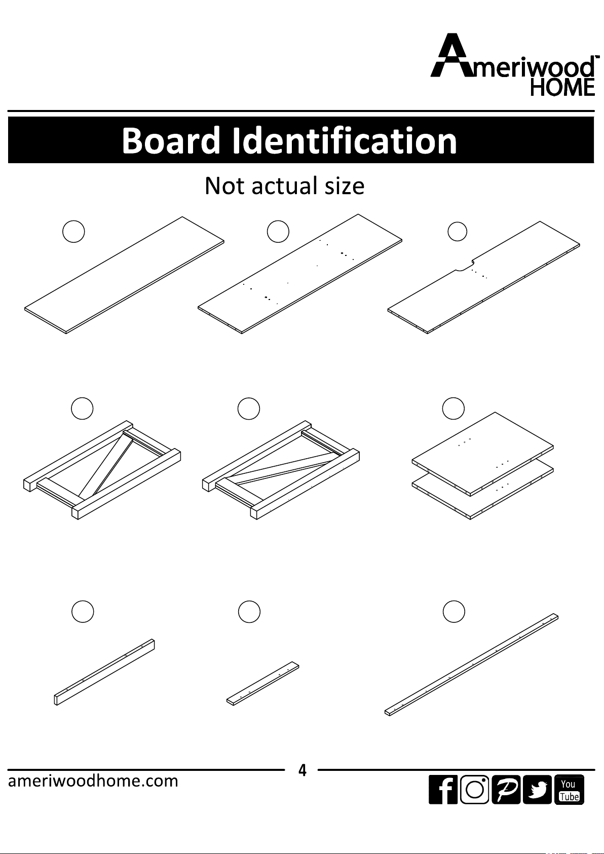
A
C
BOTTOM
T1795096020GO
QTY: 1 PC
FIXED SHELF
T1795096030GO
QTY: 1 PC
B
D
TOP
T1795096010GO
QTY: 1 PC
LEFT SIDE PANEL
T1795096040GO
QTY: 1 PC
E
RIGHT SIDE PANEL
T1795096050GO
QTY: 1 PC
PARTITION
T1795096060GO
QTY: 2 PCS
F
G
RAIL
T1795096070GO
QTY: 1 PC
H
RAIL
T1795096080GO
QTY: 2 PCS
RAIL
T1795096090GO
QTY: 1 PC
I
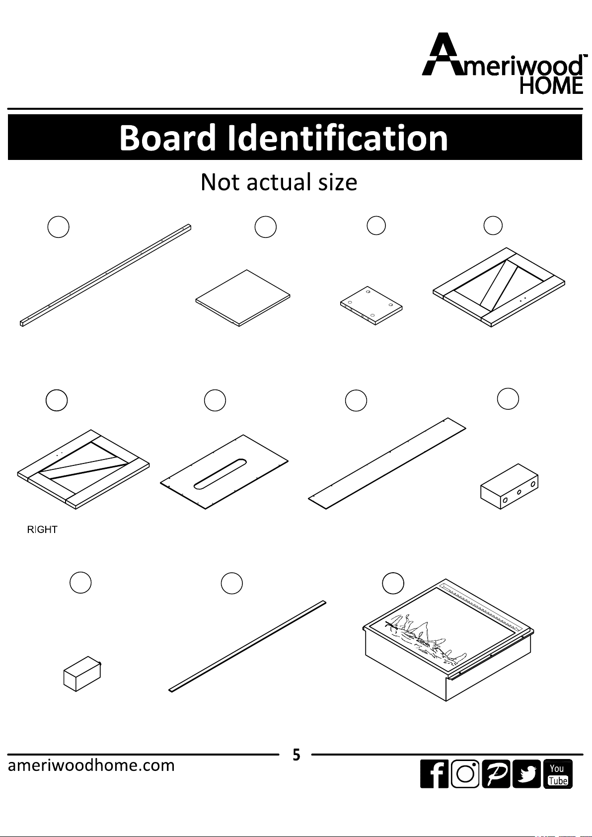
J
L
ADJUSTABLE SHELF
T1795096110GO
QTY: 2 PCS
PARTITION
T1795096120GO
QTY: 1 PC
K
O
RAIL
T1795096100GO
QTY: 1 PC
BACK PANEL
T1795096150GO
QTY: 2 PCS
P
UPPER BACK PANEL
T1795096160GO
QTY: 1PC
STOPPER
T1795096170GO
QTY: 1PC
Q
R
FOOT
T1795096180GO
QTY: 2PCS
S
RAIL
T1795096190GO
QTY: 1PC
M
LEFT DOOR
T1795096130GO
QTY: 1 PC
FRIREPLACE
QTY: 1PC
T
N
DOOR
T1795096140GO
QTY: 1 PC
FA23V60L-1
T
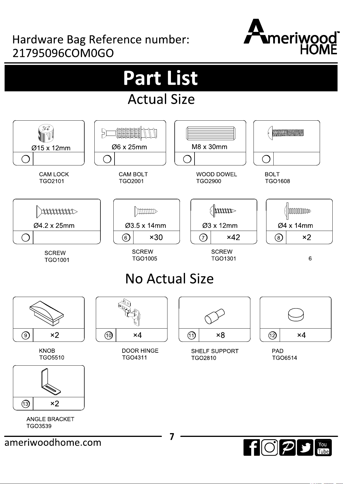
1
M4 x 19mm
432
×36 ×36 ×38 ×4
5
×5
SCREW
TGO130
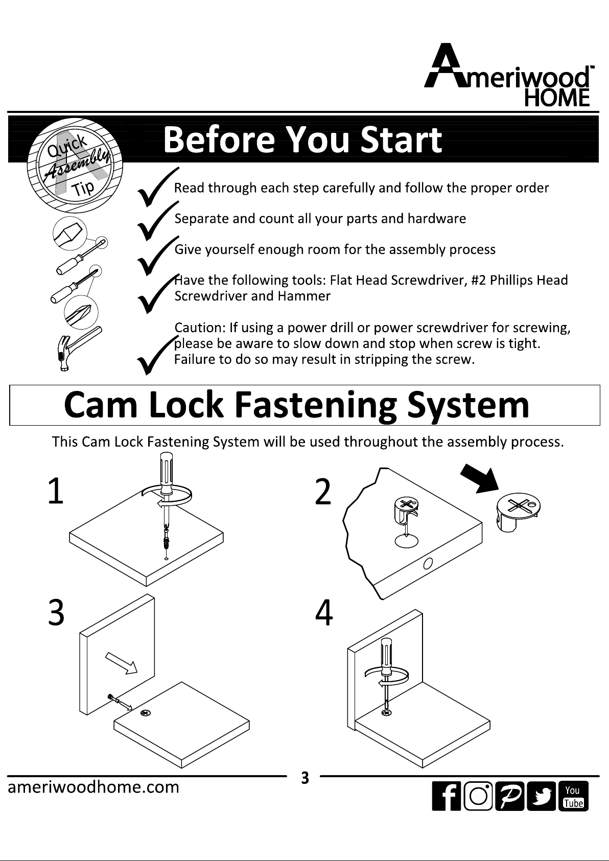
2
3
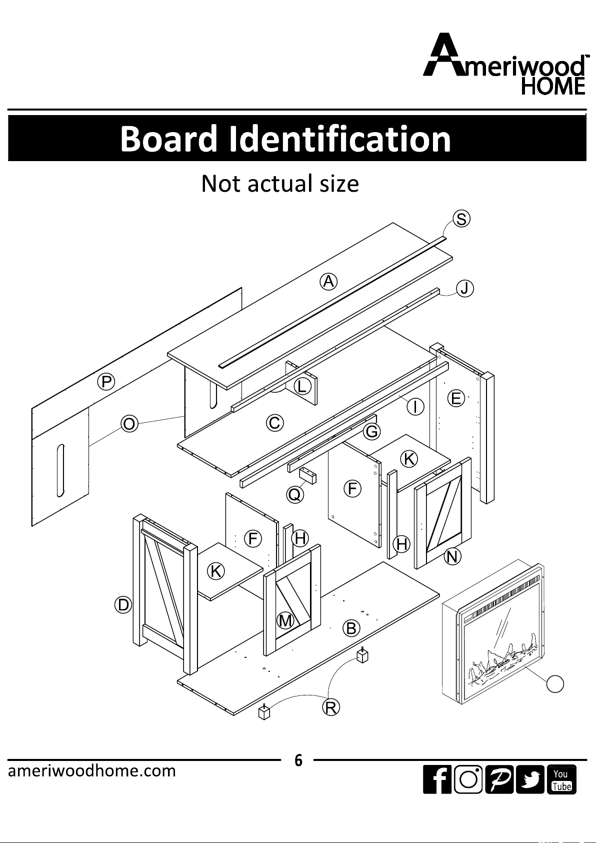
A
B
I
J
Q
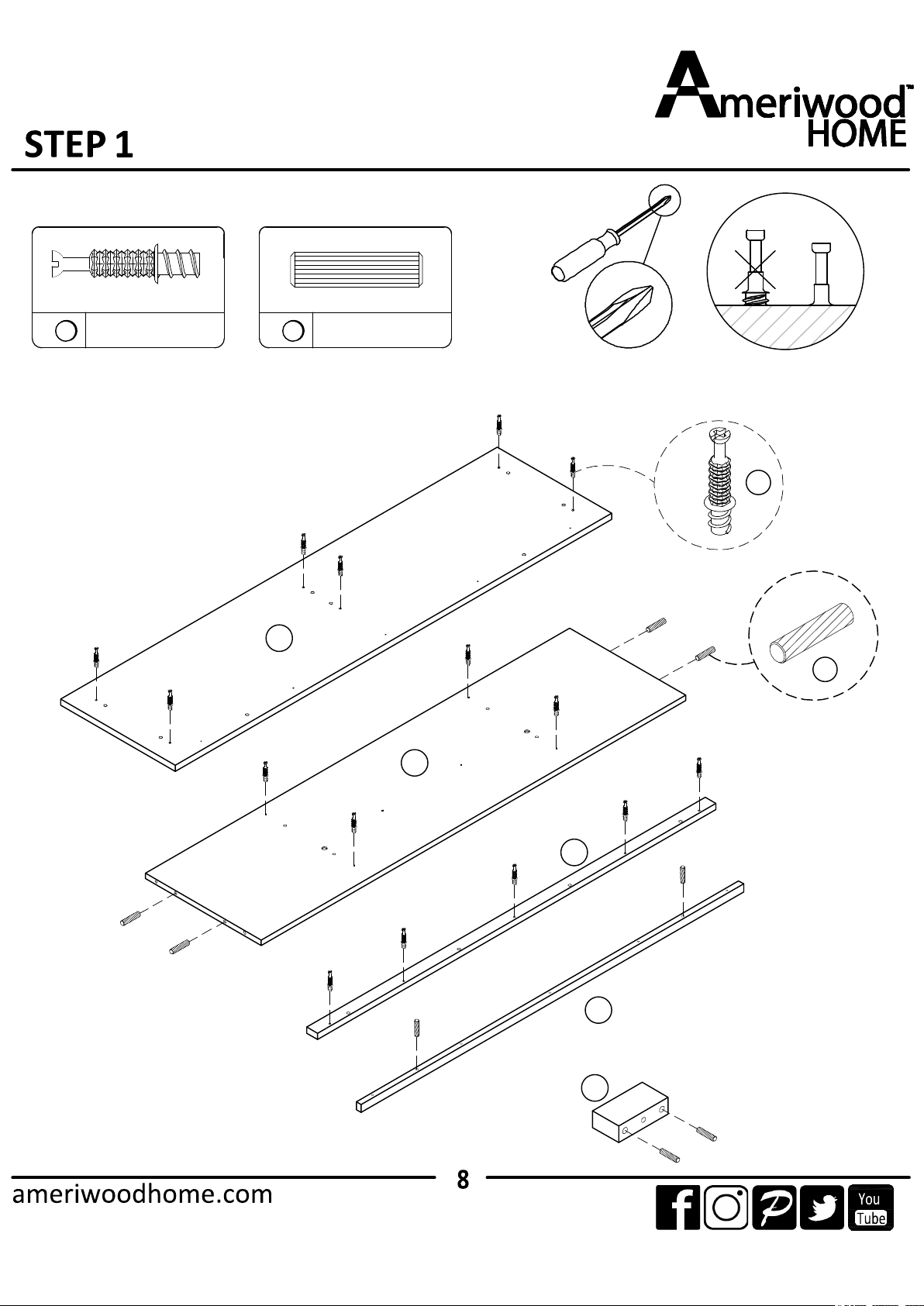
1.1 Cam bolt (2) into (A), (B) and (I) as illustrated.
1.2 Insert (3) into (B), (J) and (P) as illustrated.
3
×8 ×15
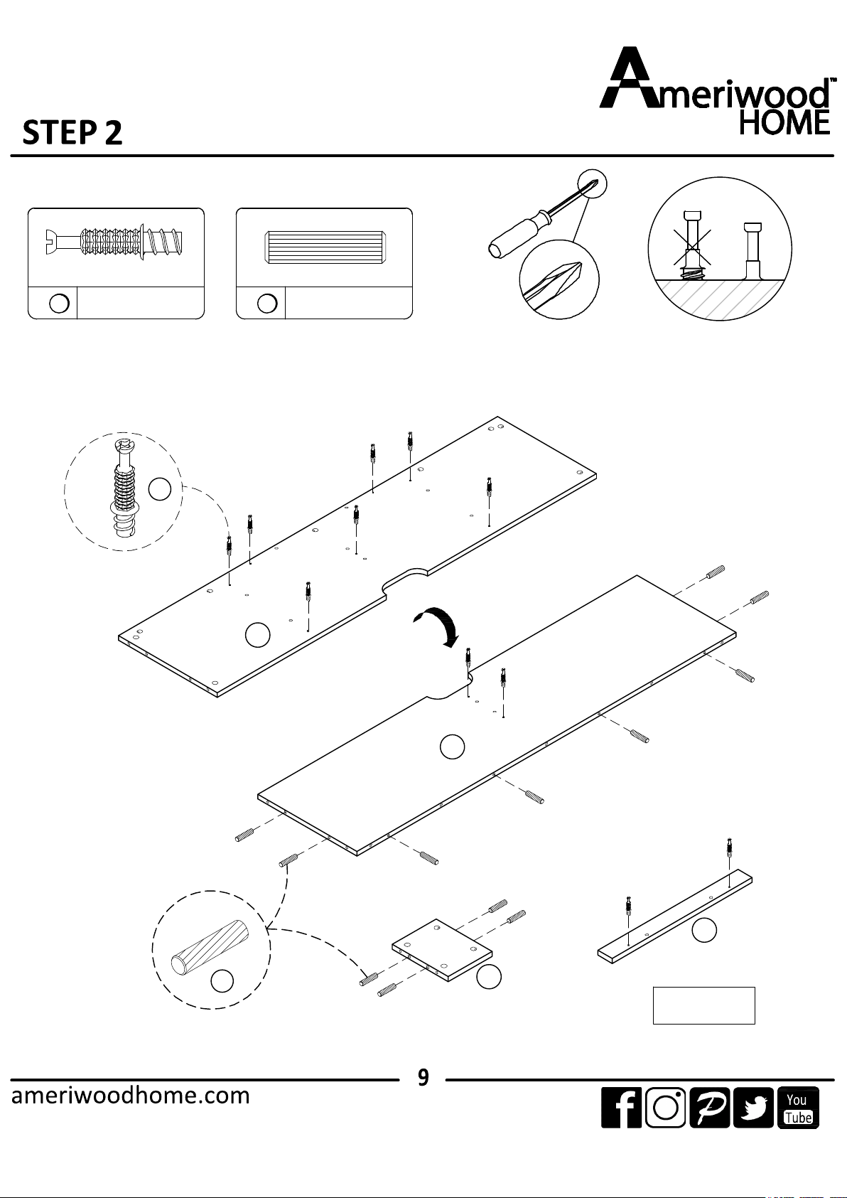
2.1 Cam bolt (2) into (C) and (H x 2) as illustrated.
2.2 Insert (3) into (C) and (L) as illustrated.
3
×11
2
×13
H X 2
C
C
L
H
3
2
3
×18
2
×8
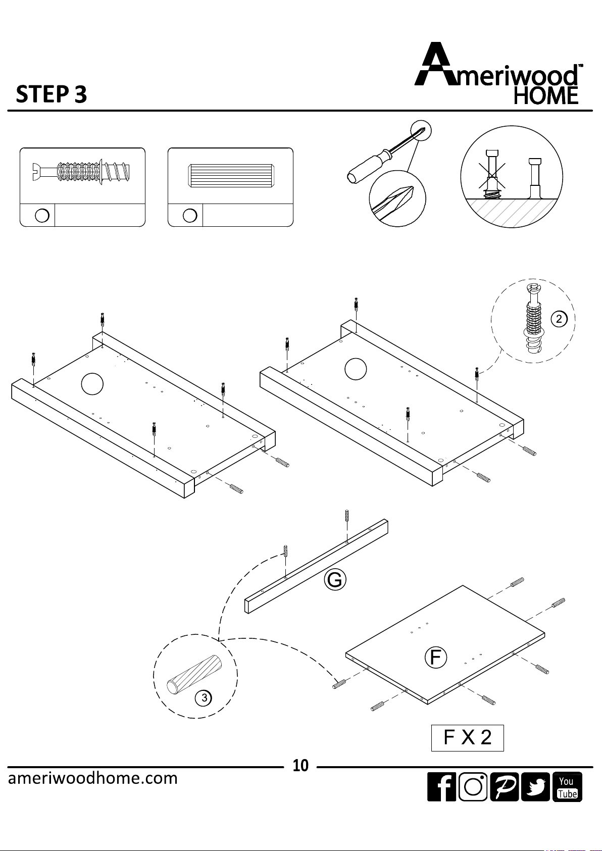
3.1 Cam bolt (2) into (D) and (E) as illustrated.
3.2 Insert (3) into (D), (E), (G) and (F x 2) as illustrated.
D
E
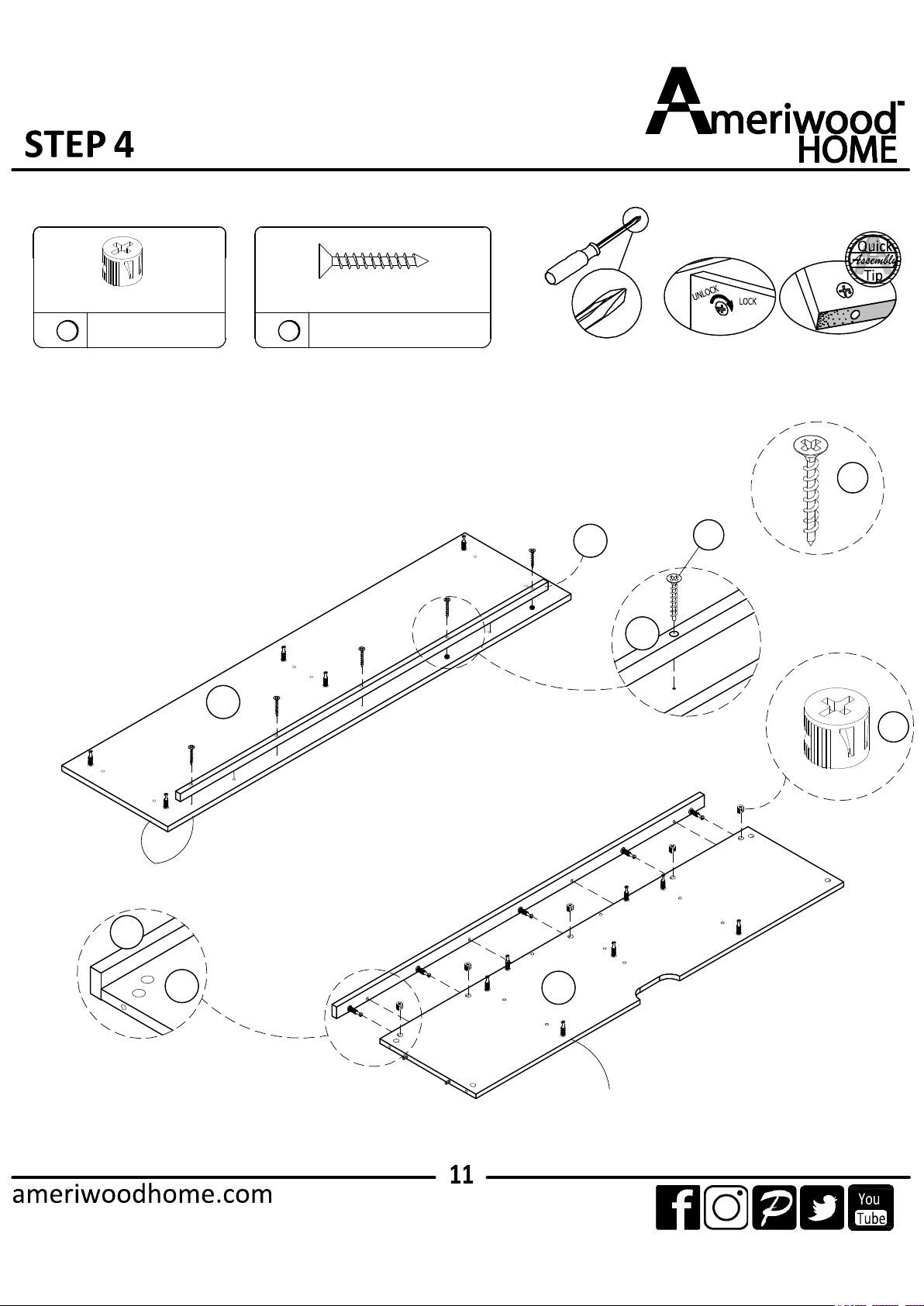
4.1 Attach (J) into (A) with (5) as illustrated.
4.2 Attach (I) into (C) with (1) as illustrated.
Proper orientation of CAM LOCK
1
5
×5
5
J
5
1
A
C
C
I
J
UNFINISHED EDGE
FINISHED EDGE
×5
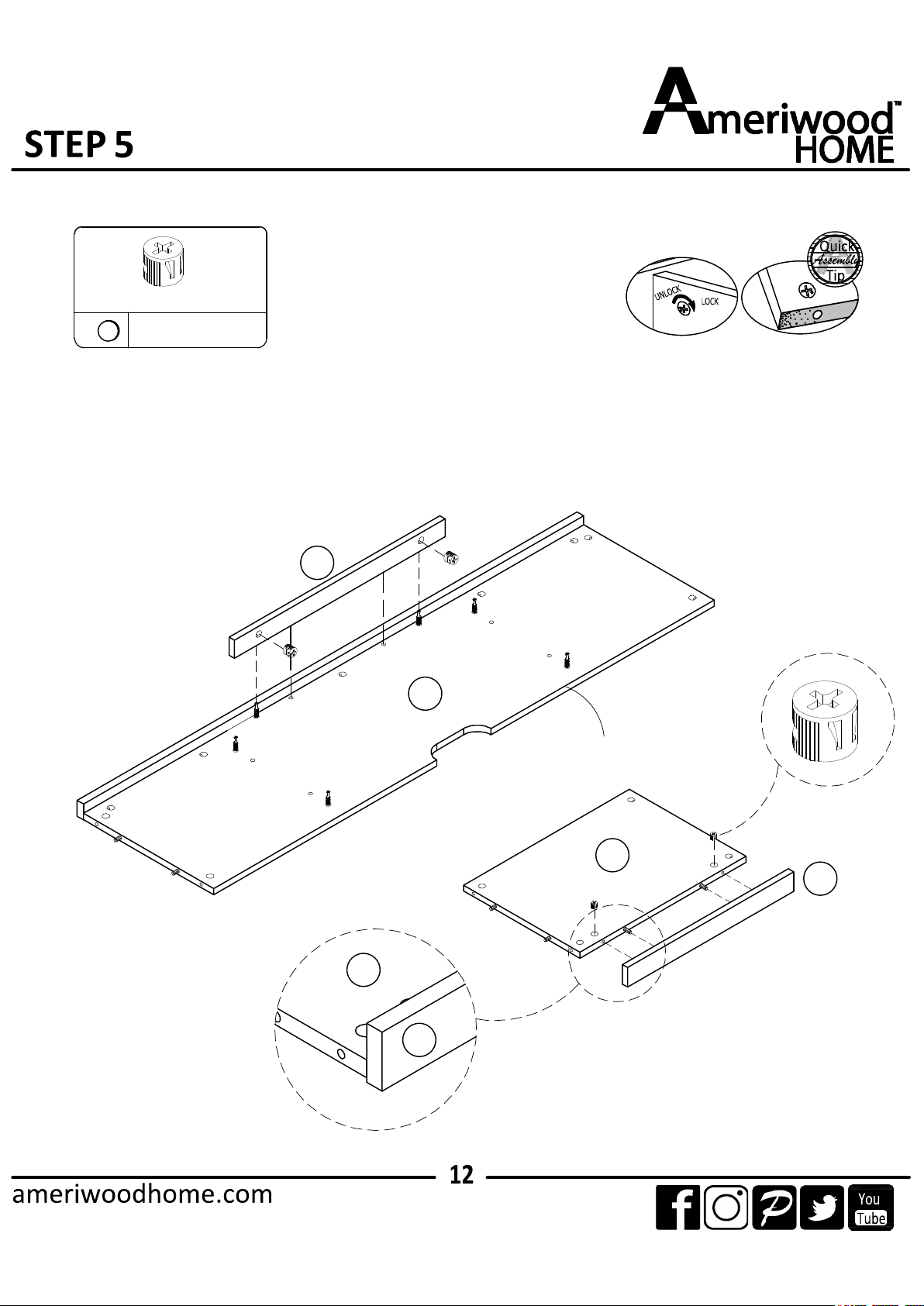
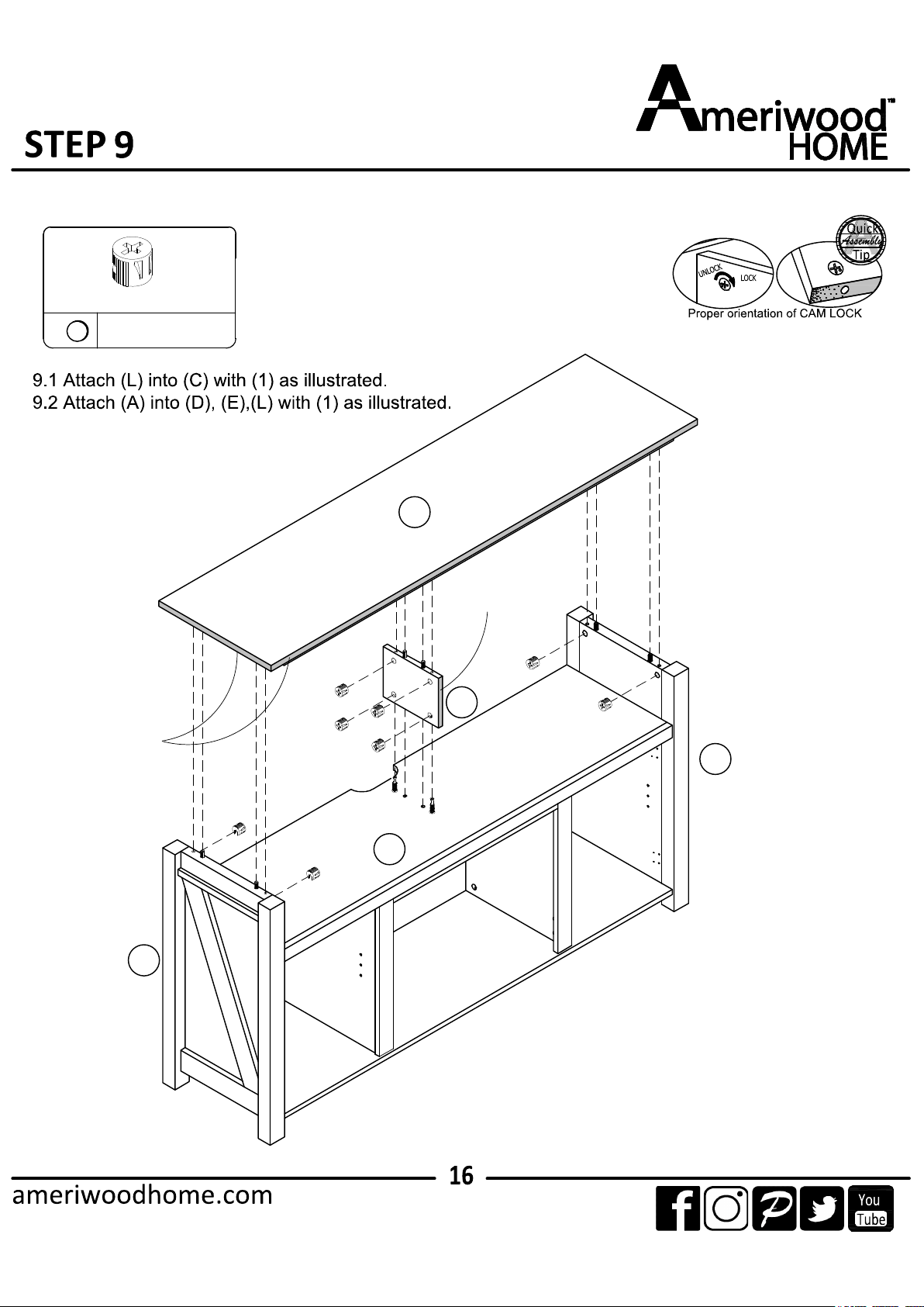
5.1 Attach (G) into (C) with (1) as illustrated.
5.2 Attach (H) into (F) with (1) as illustrated.
Proper orientation of CAM LOCK
1
H
F
F
H
x 2
C
G
×6
UNFINISHED EDGE
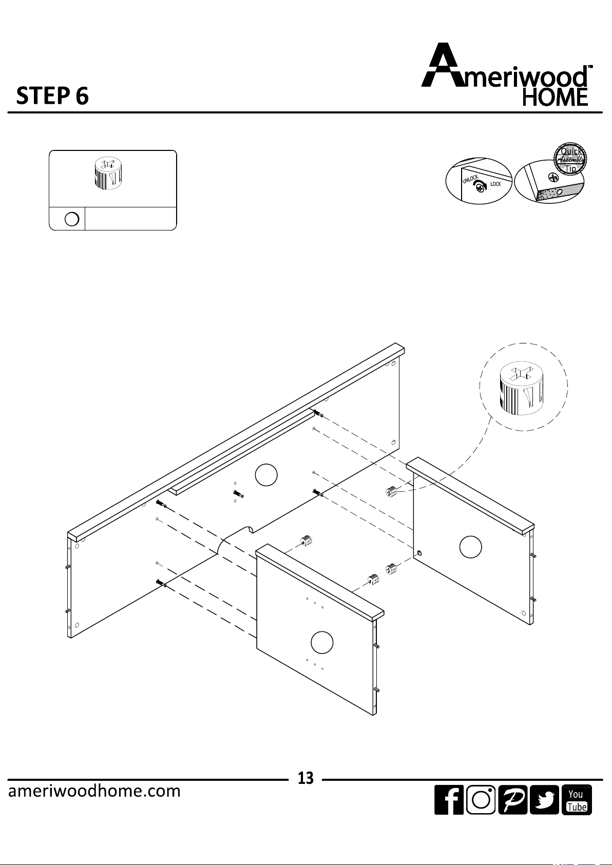
Proper orientation of CAM LOCK
6.1 Attach (F) into (C), with (1) as illustrated.
C
F
F
1
×4
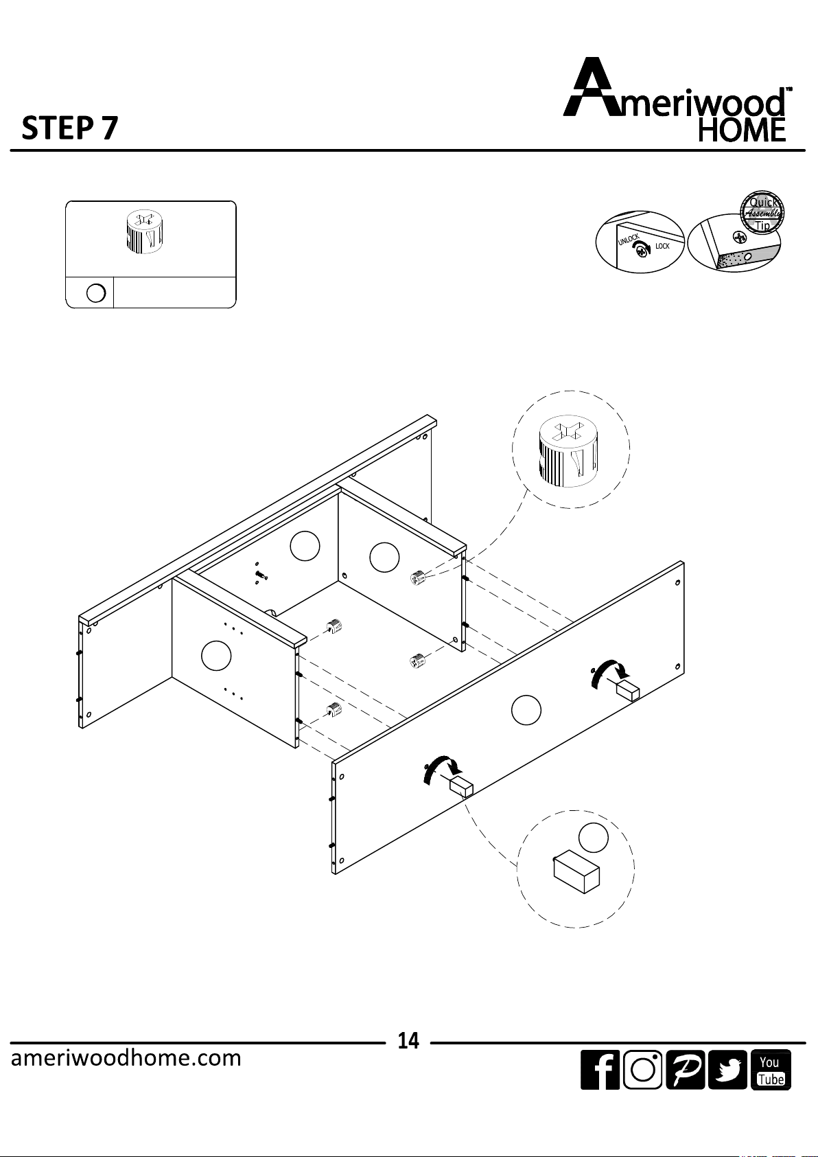
7.1 Attach (B) into (F) with (1) as illustrated.
7.2 Attach (Q) into (B) as illustrated.
F
F
C
B
R
Proper orientation of CAM LOCK
1
×4
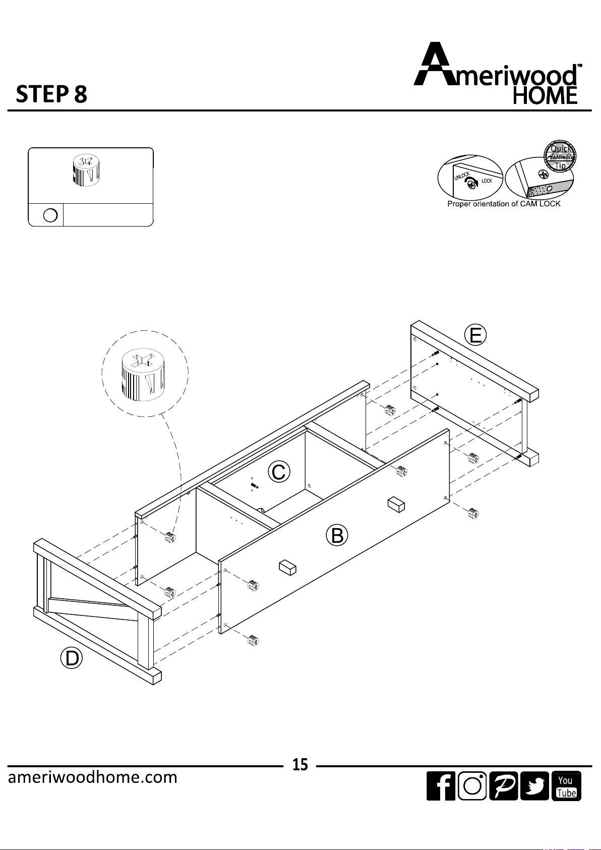
8.1 Attach (D) and (E) into (C), (B) with (1) as illustrated.
1
×8
A
1
L
E
D
C
FINISHED EDGE
FINISHED EDGE
×8
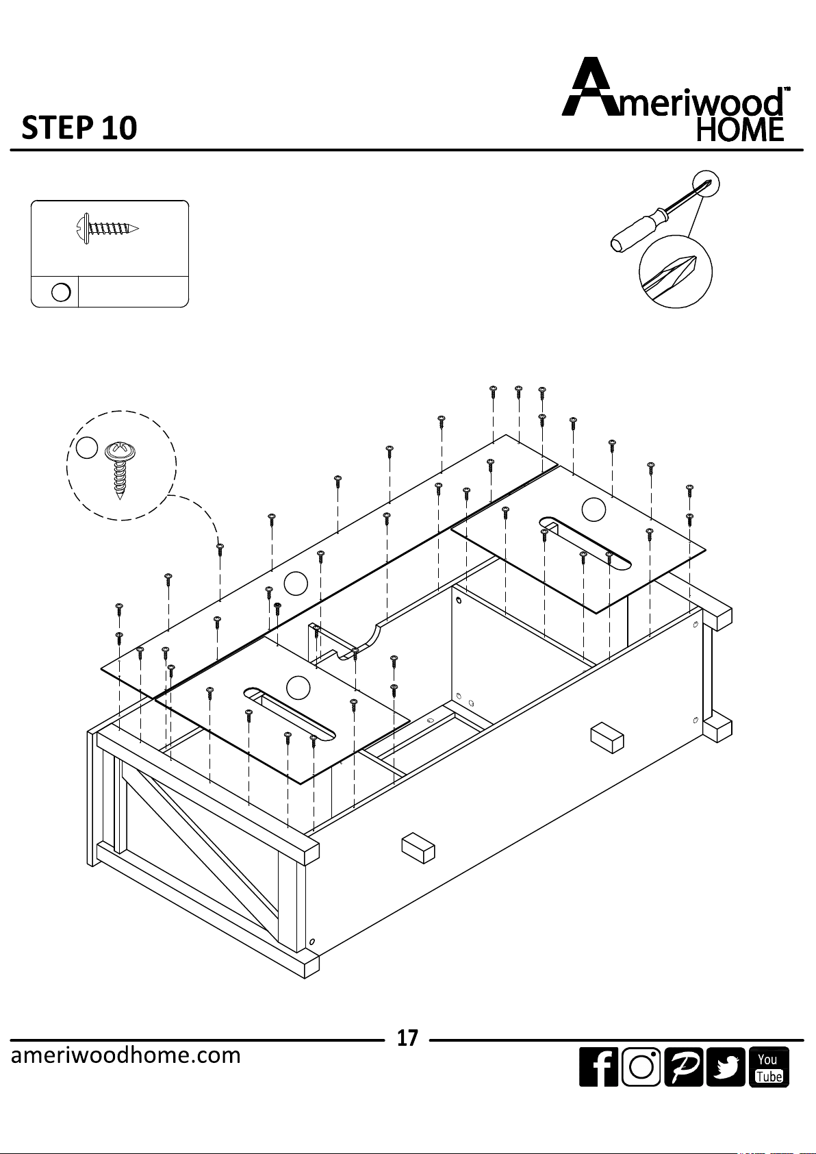
10.1 Attach (P), (O) into (C) with (1) as illustrated.
7
×42
O
O
P
7
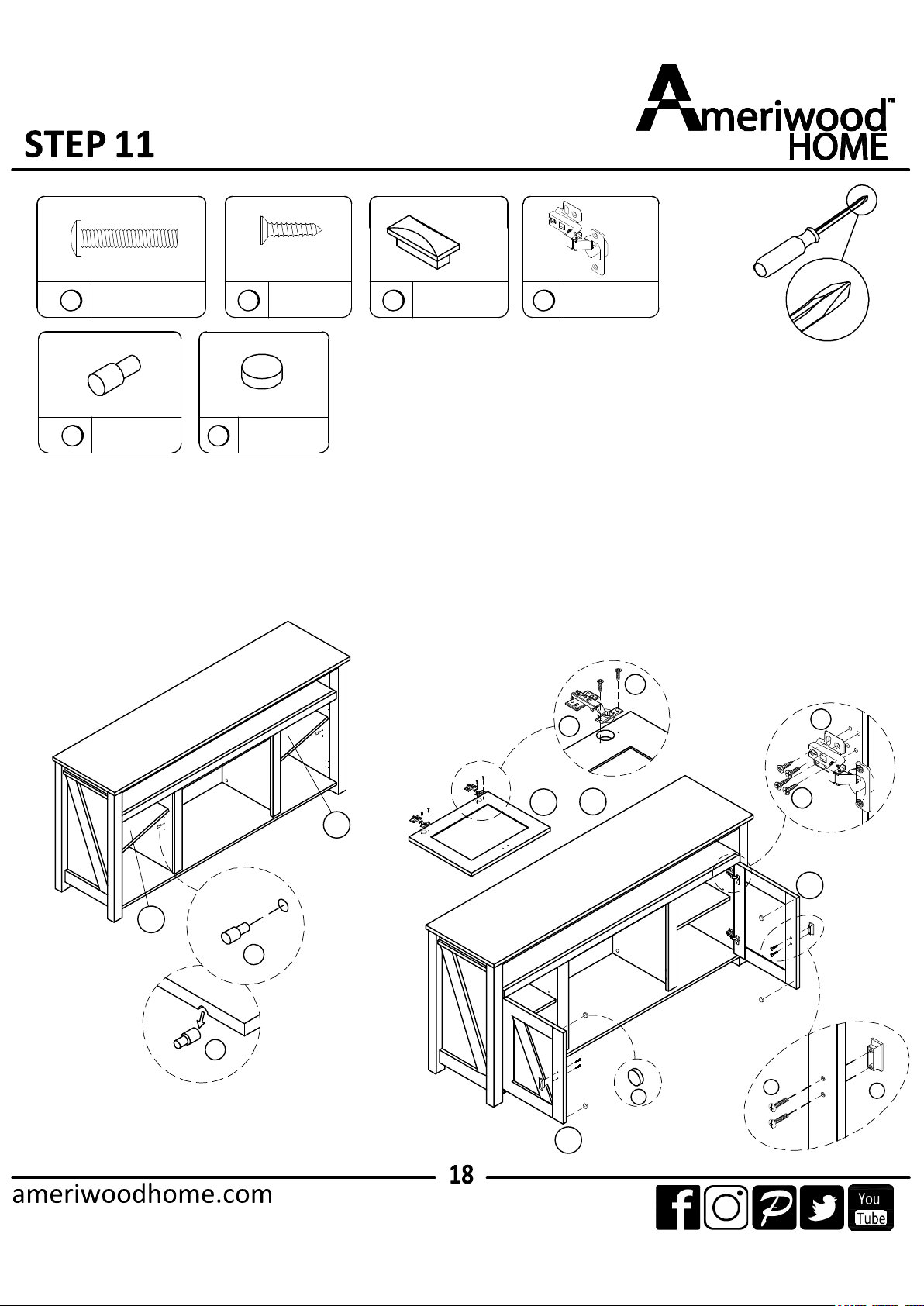
11.1 Attach (K) with (11) as illustrated.
11.2 Attach (10) into (M), (N) with (6) as illustrated.
11.3 Attach (10), (M),(N) into (D), (E) with (6) as illustrated.
11.4 Attach (9) into (M), (N) with (4) as illustrated.
11.5 Attach (12) into (M),(N) as illustrated.
4
6
9
×2
10
×4
11
×8
12
×4
11
11
K
K
×4 ×24
6
10
10
6
M
&
N
9
4
12
M
N
A
A
B
C
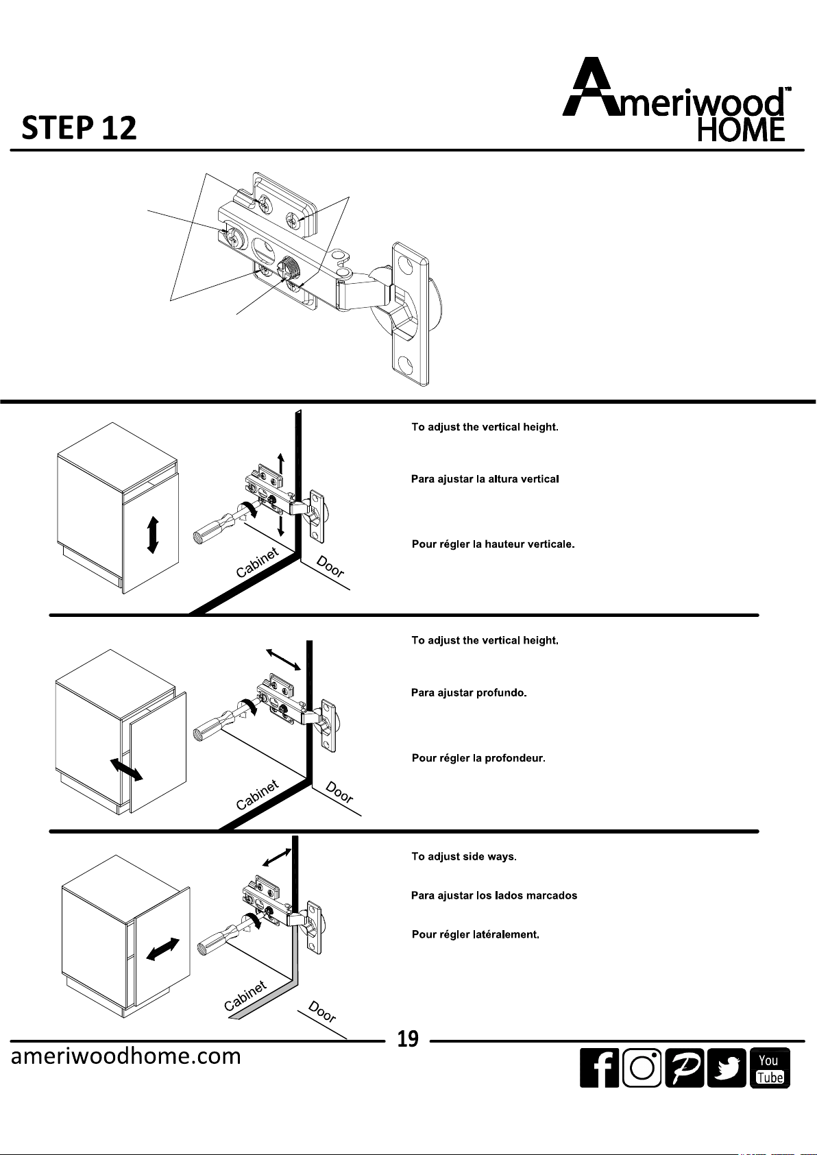
Loosen the four screws "A" on bolt hinges. Two of them are usually in slotted
holes which allows you to adjust up of down by a few mm. then tighten back up.
Afloje los cuatro tornillos "A" en ambas bisagras. Dos de esos están usualmente
en los agujeros llanos. Lo que significa que usted puede regular de arriba hacia
abajo. Por unos pocos milimetros. Luego apriete hacia arriba.
Desserrez les quatre vis "A" sur les deux charnières. Deux d'entre elles sont
habituellement dans des fentes afin de vous permettre de les vis après
l'ajustement.
Turning the screw "C" on BOTH hinges on each door.
Gire los tornillos "C" de ambas bisagras en cada puerta
Tournez la vis "C" sur les DEUX charnières de chaque porte.
Loosen screw "B" and adjust door, if the door can not be adjusted, please
loosen screw "C", then try again. Tighten screw "B" and "C".
Afloje los tornillos y ajuste la puerta, si la puerta no puede ser ajustada. Por
favor afloje los tornillos "C" y luego trate otra vez.
Apriete los tornillos "B" y "C"
Desserrez la vis "B" et ajustez la porte. Si la porte ne peut pas s'ajuster,
desserrez la vis "C", pui essayez de nouveau.
Serrez les vis "B" et "C".
6
×6
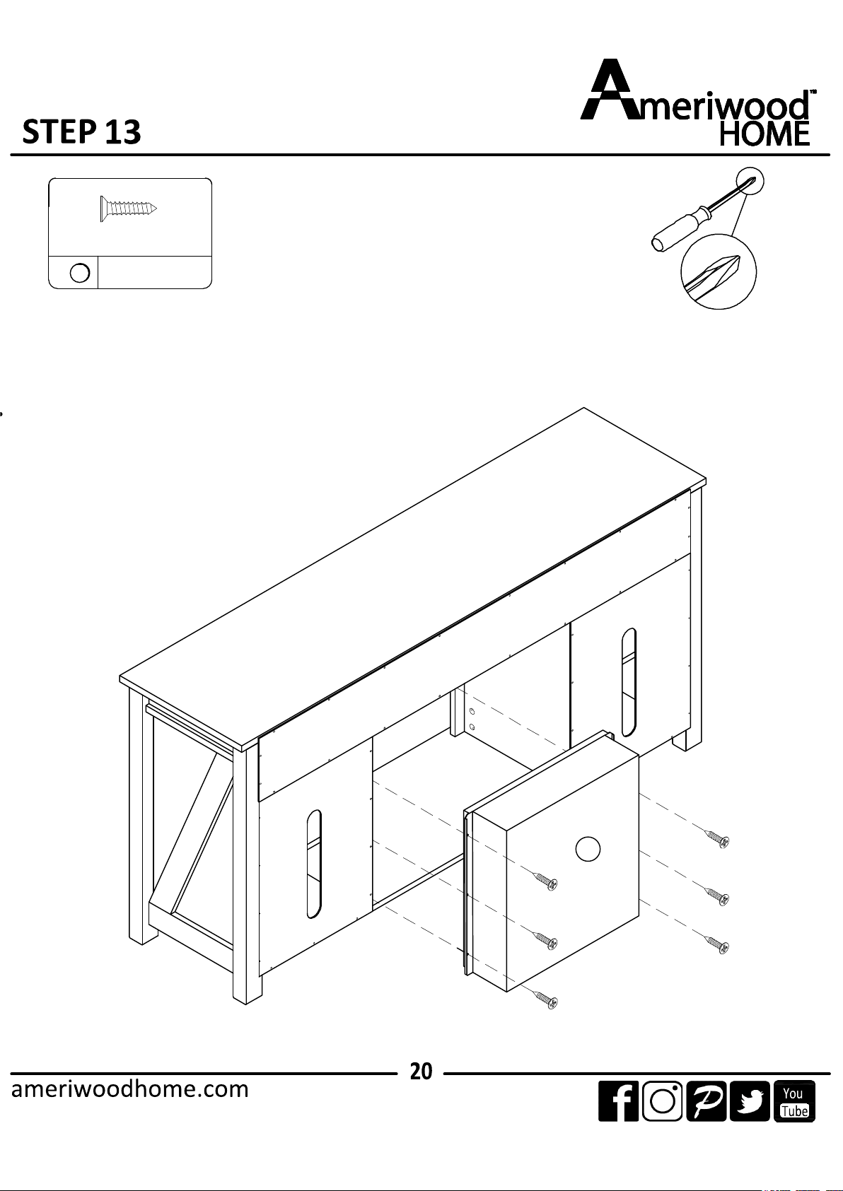
13.1 Attach (T) from backside with (6) as illustrated.
T
1
×1
8
×2
Ø4 x 14mm
13
×2
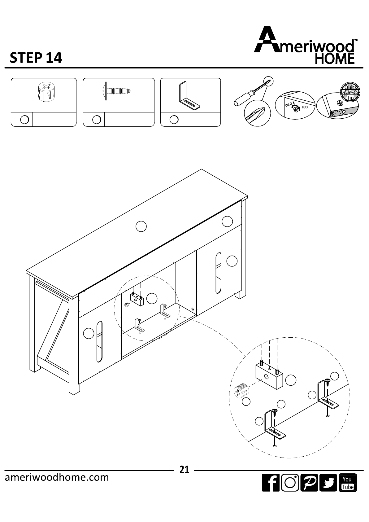
Proper orientation of CAM LOCK
Q
1
8
8
13
13
14.1 Attach (Q) into (C) with (1) as illustrated.
14.2 Attach (13) into (B) with (8) as illustrated.
P
O
O
A
Q
S
S
A
S
leveler
R
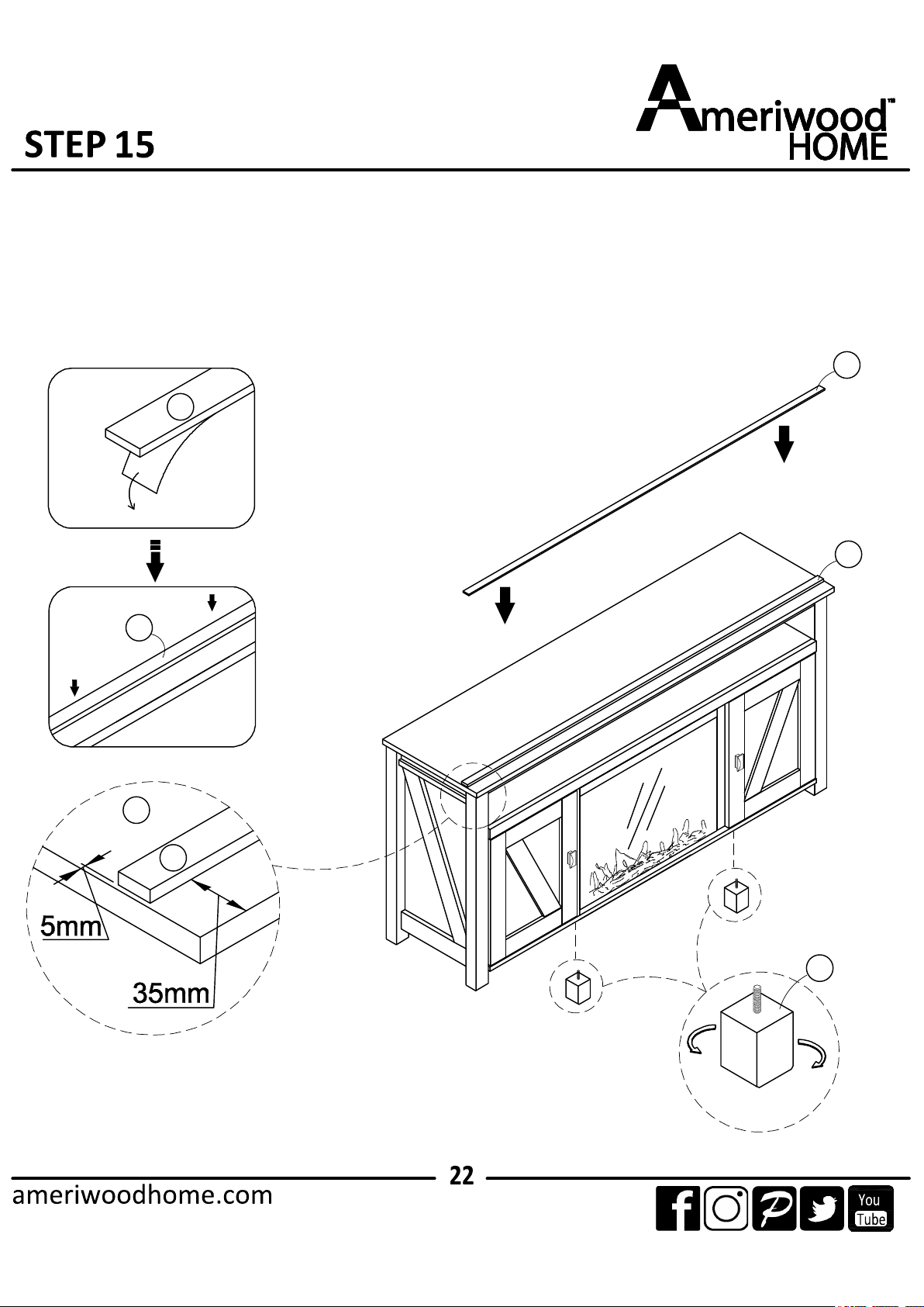
15.1 Attach (S) into (A) as illustrated.
15.2 Adjust the foot (R) before use.
S
S