
Loading ...
PK-93827-10-02-2A
Single Pole (One location)
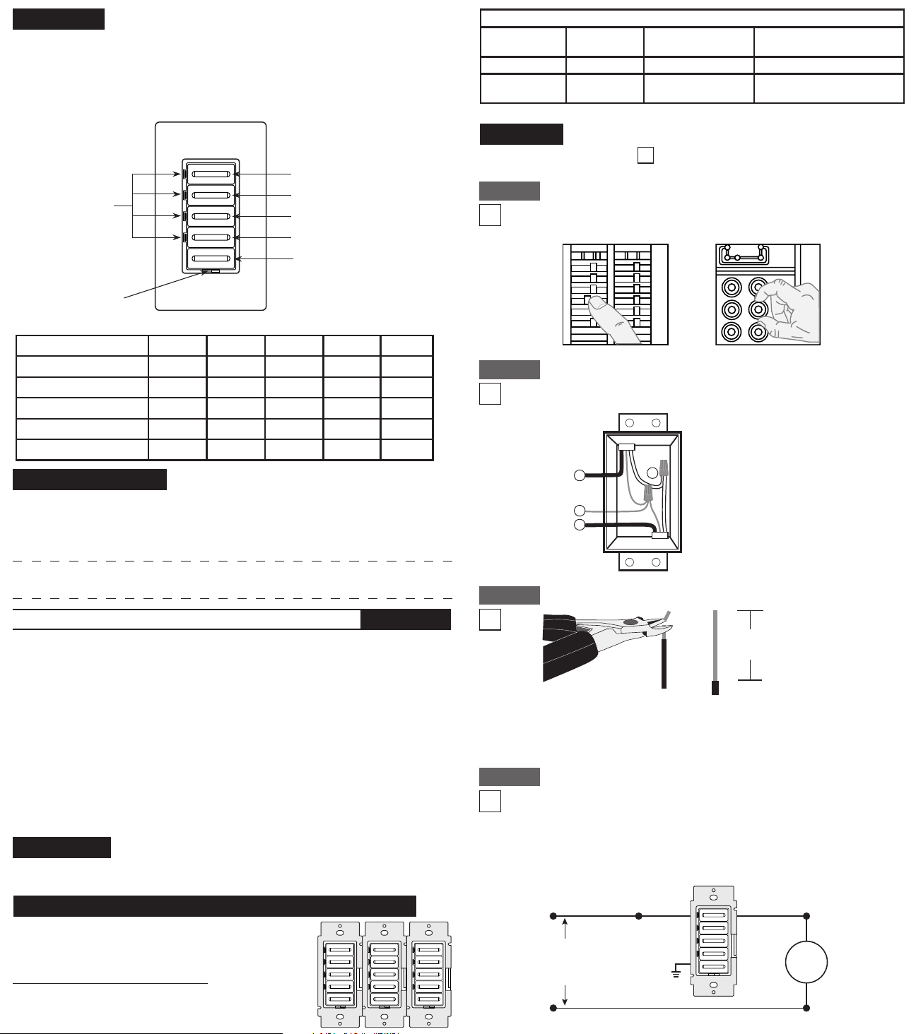
5 Button Countdown Timer
Cat No. 6161T - 120VAC, 60Hz, 500W Incandescent
Cat. Nos. LTT15, LTT60, LTT30, LTT12
120VAC, 60Hz, 600W Incandescent, 5A Resistive, 5A Tungsten
INSTALLATION INSTRUCTIONS
Unipolaire (un emplacement)
Minuterie de compte à rebours à cinq boutons
N
o
de Cat. 6161T – 120 V c.a., 60 Hz, 500 W (à incandescence)
Nos de cat. LTT15, LTT60, LTT30, LTT12 - 120 V c.a., 60 Hz,
600 W (à incandescence), 5 A (résistive), 5 A (au tungstène)
DIRECTIVES D’INSTALLATION
Unipolar (1 Ubicación)
Cronómetro de cuenta regresiva de 5 botones
No. de Cat. 6161T – 120VCA, 60Hz, 500W Incandescente
Nos. de Cat. LTT15, LTT60, LTT30, LTT12 - 120VCA, 60Hz,
600W Incandescente, 5A Resistivo, 5A Tungsteno
INSTRUCCIONES DE INSTALACION
AVERTISSEMENT : pour éviter les risques d’incendie, de choc
électrique ou d’électrocution, COUPER LE COURANT au fusible ou au
disjoncteur et s’assurer que le circuit soit bien coupé avant de procéder
au câblage.
WARNINGS AND CAUTIONS:
• Tobeinstalledand/orusedinaccordancewithelectricalcodesandregulations.
• Ifyouareunsureaboutanypartoftheseinstructions,consultanelectrician.
• Toavoidoverheatingandpossibledamagetothisdeviceandotherequipment,
donotinstalltocontrolareceptacle,uorescentlighting,amotor-oratransformer-
operated appliance.
• Usewithincandescentor120Vhalogenxturesonly.
• Totalminimumloadmustexceed40W.
• Recommendedminimumwallboxdepthis2-1/2”.
• Disconnectpoweratcircuitbreakerorfusewhenservicing,installingorremovingxture.
• UsethisdeviceWITH COPPER OR COPPER CLAD WIRE ONLY.
Tools needed to install your Timer
Slotted/PhillipsScrewdriver ElectricalTape
Pliers Pencil
Cutters Ruler
Installing your Timer
√
NOTE: UsecheckboxeswhenStepsarecompleted.
Installation
√
REMARQUE: cocher les cases une fois les étapes complétées.
ONOFF
ONOFF
ONOFF
ONOFF
ONOFF
ONOFF
ONOFFONOFF
ONOFF
ONOFF
ONOFF
ONOFF
Step 1
WARNING: TO AVOID FIRE, SHOCK, OR DEATH; TURN OFF
POWER atcircuitbreakerorfuseandtestthatpowerisoffbeforewiring!
• S’assurerquelesbrinsdeslsdelaboîtemuralesoientbiendroits
(les recouper au besoin).
• Dénuderl’extrémitédechaqueldelaboîtemuraledelamanièreillustrée.
Préparation et raccordement des ls :
Gabarit de dénudage
(pour mesurer les ls
dénudés)
1.6 cm
(5/8")
Couper
(au besoin)
Étape 3
ONOFF
ONOFF
ONOFF
ONOFF
ONOFF
ONOFF
ONOFFONOFF
ONOFF
ONOFF
ONOFF
ONOFF
Étape 1
2
4
3
1
Single-Pole
1. Line (Hot)
2. Neutral
3. Ground
4. Load
NOTE: A neutral connection is not
required for this device.
Identication de l’application (plus courantes montrées) :
REMARQUE :silesraccordsàl’intérieurdelaboîteneressemblentpas
dutoutàceuxmontrésici,ondoitfaireappelàunélectricienqualié.
Étape 2
2
4
3
1
Unipolaire
1. Ligne (actif)
2. Neutre
3. Terre
4. Charge
REMARQUE: ce dispositif ne requiert
pas de raccordement
au neutre.
Step 2
Identifying your wiring application (most common):
NOTE:Ifthewiringinthewallboxdoesnotresembleanyofthese
congurations,consultaqualiedelectrician.
Preparing and connecting wires:
• Makesurethattheendsofthewiresfromthewallboxarestraight (cut if necessary).
• Removeinsulationfromeachwireinthewallboxasshown.
Strip Gage
(measure bare wire here
or use gage on back of
the timer)
5/8"
(1.6 cm)
Cut
(if necessary)
Step 3
Single-Pole Wiring Application:
Connect wires per WIRING DIAGRAM as follows:
Twiststrandsofeachleadtightlyand,withcircuitconductors,pushrmlyinto
appropriatewireconnector.Screwconnectorsonclockwisemakingsurethat
nobarewireshowsbelowthewireconnectors.Secureeachwireconnector
withelectricaltape.
Step 4
Timer
Hot (Black) Black
Black
Black
Neutral (White)
Line
120VAC
60Hz
White
Green
Ground
Load
Restore Power: Restorepoweratcircuitbreakerorfuse.
Installation is complete.
Step 7
Timer Mounting:
TURN OFF POWER AT CIRCUIT BREAKER OR FUSE.
Step 6
Installationmaynowbecompletedby
tighteningmountingscrewsintowallbox.
Attachwallplate.
NOTE: Dresswireswithabendas
shownindiagraminordertorelieve
stresswhenmountingdevice.
Testing your Timer prior to mounting in wall box:
Step 5
• Restorepoweratcircuitbreakerorfuse.
• Makesureslideswitchisinthe(ON)position-
located to the right (see OPERATION). Press
anyoneofthetimerbuttonsandthelightswill
turn ON.
If lights DO NOT turn ON refer to
Troubleshooting section.
• Positionallwirestoprovideroominoutletwallbox
for device.
• Ensurethattheword“TOP”isfacingupondevice
strap.
• Partiallyscrewinmountingscrewsinwallbox
mounting holes.
1. ToturnthelightsONpressoneofthetimeoutbuttons.Thiswillcommencetimecount
downandthegreenLEDnexttothatbuttonwillturnon.
2. ToturnthelightsOFFwaituntiltheselectedtimehaspassed(theLEDnexttoeach
buttonwillextinguishastimeoutpassestothenextpresetlevel)orpresstheOFFbutton.
3. PressingandholdingthetopbuttonuntilallLEDsturnonwilloverridethetimeoutfeature
andthelightswillstayonuntilatimeoutbuttonortheOFFbuttonispressed.
OPERATION
• Lights and LED do not turn ON
- Checkwiring
- Checktoseeifcircuitbreakerorfusehastripped
- CheckthatslideswitchisintheONposition(locatedtotheright)
TROUBLESHOOTING
Button 4/Override switch
Button 3
Green
LED indicator
lights
Button 2
Button 1
OFF switch
ON/OFF slide switch
Outils requis
Tournevisordinaire/Phillips Rubanisolant Pinces
Crayon Coupe-l Règle
DIRECTIVES D’INSTALLATION
FRANÇAIS
AVERTISSEMENTS ET MISES EN GARDE :
• Installerouutiliserconformémentauxcodesdel’électricitéenvigueur.
• Àdéfautdebiencomprendrelesprésentesdirectives,entoutouenpartie,ondoitfaire
appelàunélectricienqualié.
• Pouréviterlasurchauffeoul’endommagementéventueldecedispositifetdes
appareils qui lui sont raccordés, ne pas l’installer pour commander une prise, de
l’éclairageuorescentouunappareilmotoriséouàtransformateur.
• N’utilisercedispositifqu’enprésenced’appareilsd’éclairageàincandescenceouà
halogène de 120 V
• Lachargetotaleminimaledoitêtresupérieureà40W.
• Profondeurrecommandéepourlaboîtemurale:6,4cm(21/2po).
• Couperl’alimentationaufusibleouaudisjoncteuravantdemanipuler,d’installeroude
retirer les luminaires commandés.
• N’utilisercedispositifqu’avecduFIL DE CUIVRE OU PLAQUÉ CUIVRE.
Si la minuterie est installée seule, passer à la section
INSTALLATION. Si elle est groupée avec d’autres dispositifs,
procédercommesuit:
Installation de la minuterie seule, ou avec d’autres dispositifs
INSTALLATIONS GROUPÉES
Lorsque ce dispositif est installé en groupe, on doit en
réduire la capacité nominale. Se reporter au tableau
CHARGE MAXIMALE/MINUTERIE.
Applications unipolaires:
Raccorder les ls conformément au schéma de câblage et
de la façon suivante : torsader solidement ensemble les brins de
chaqueconnexionetenfoncerfermementleraccorddansunserre-
lsdecalibreapproprié,entournantcedernierversladroiteeten
s’assurantqu’aucunbrindecuivrenesoitexposé.Protégerlesraccords
aumoyenderubanisolant.
Minuterie
Actif (Noir) Noir
Noir
Noir
Neutre (Blanc)
Ligne
120 V c.a.
60Hz
Blanc
Terre
vert
Charge
Étape 4
Product Button 1 Button 2 Button 3 Button 4 Time
6161T(10,20,30,60M) 10 20 30 60 Minutes
LTT15(2,5,10,15M) 2 5 10 15 Minutes
LTT30(5,10,15,30M) 5 10 15 30 Minutes
LTT60(10,20,30,60M) 10 20 30 60 Minutes
LTT12(2,4,8,12H) 2 4 8 12 Hour
NOTE:EnsureslideswitchisintheOFFpositionwhenchangingthebulb.
MULTI-DEVICE APPLICATION
Inmulti-deviceinstallations,thereductionofthetimer’scapacityisrequired.Referto
thechartformaximumloadpertimer.
IfinstallingTimerinasingledeviceapplication,proceedwiththeINSTALLING YOUR
TIMERsection.IfinstallingTimerinamulti-deviceapplication,proceedasfollows:
Installing Timer by itself or with other devices
MAXIMUM LOAD PER TIMER FOR MULTI-DEVICE
Cat. No.
LTT15, LTT30,
LTT60, LTT12
Single
500W
600W
Two Devices
300W
500W
More than 2 Devices
250W
400W
6161T
•
Degreeofprotection: IP20
•
TypeofAction: 1.B.Q
Un dispositif Deux dispositifs Plus de 2 dispositifs
CHARGE MAXIMALE/MINUTERIE
N
o
de cat.
LTT15, LTT30,
LTT60, LTT12
500W
600W
300W
500W
250W
400W
6161T
Loading ...
Loading ...