Loading ...
Loading ...
Loading ...
7
Figure 2
Media
Tray
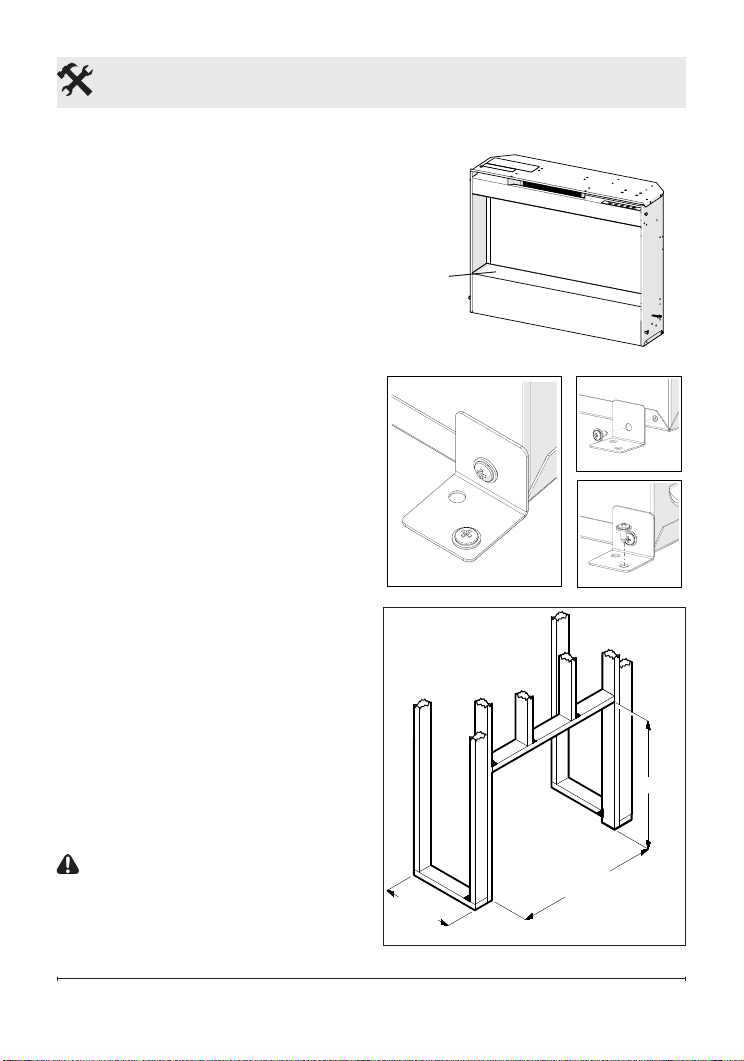
Custom Installation
1. Mark the desired location on the
oor and store the replace in a
safe, dry and dust free location.
2. Frame an opening of 24.0 in.
(610 mm) wide x 18 ½ in. (470
mm) high x 7 ⅞ in. (200 mm)
deep (Figure 4).
Option #1 - The power cord can
be lead from behind the trim and
along the wall to an outlet near the
replace.
Option #2 - A new outlet can be
installed inside the new frame con-
struction. Plug the unit directly into
a 15 A, 120 V outlet.
!
NOTE: A 15 Amp, 120 Volt
circuit is required. A dedicated
circuit is preferred but not essential
in all cases. A dedicated circuit will
be required if, after installation, the
circuit breaker trips or fuse blows
on a regular basis when the heater
is operating. Additional appliances
on the same circuit may exceed the
current rating of the circuit breaker.
3. Install the provided plastic feet
to the unit as shown in Figure 5.
CAUTION: Clearance for air
circulation beneath the replace
insert is provided by feet.
Do not install the replace
Fireplace Installation
Figure 3
Figure 4
24.0 in.
(610 mm)
18 ½ in.
(470 mm)
7 ⅞ in.
(200 mm)
Loading ...
Loading ...
Loading ...