Owner's Manuals 2019 Volkswagen Atlas
3.6L
(3.6L S; 3.6L SE; 3.6L SE w/Technology; 3.6L SE
w/Technology R-Line; 3.6L SEL;3.6L SEL R-Line;3.6L SEL
Premium)
Vehicle overview
Front view
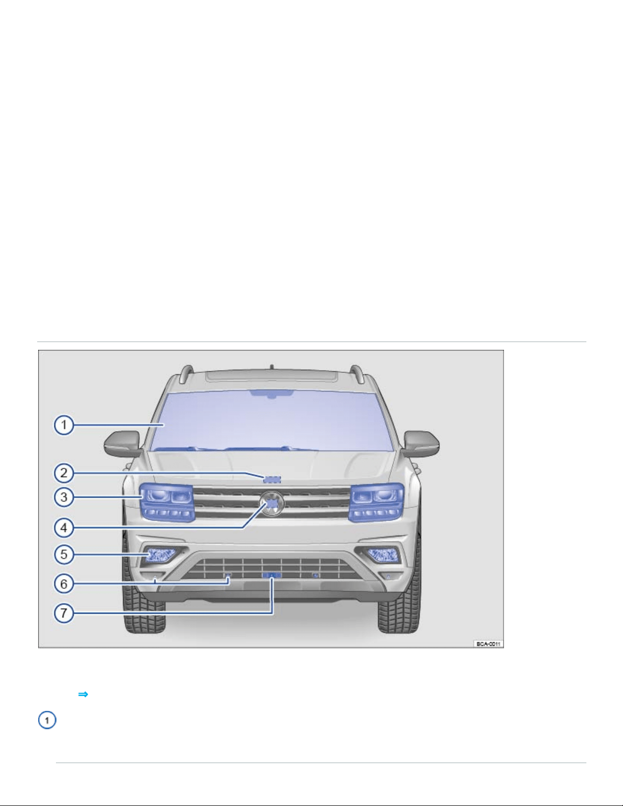
Fig.1Vehicle front overview.
Key to ⇒Fig.1 :
Front windshield:
- Vehicle Identification number (VIN) ⇒Technical data

- Windshield heating ⇒Windshield heating
- Windshield wipers ⇒Windshield wipers and washer
- Camera for assistance systems ⇒Driver assistance systems
- Rain sensor (if equipped) ⇒Windshield wipers and washer
- Low-light sensor (if equipped) ⇒Lights
- Light Assist (if equipped) ⇒Lights
Engine hood release ⇒In the engine compartment
Headlights (on left and right) ⇒Lights ⇒Replacing light bulbs
Radar sensor behind the Volkswagen emblem:
- Adaptive Cruise Control (ACC) (if equipped) ⇒Adaptive Cruise Control (ACC)
- Front Assist (if equipped) ⇒Forward Collision Warning (Front Assist)
Fog lights/static cornering lights (on left and right, if equipped) ⇒Lights ⇒Replacing light bulbs
Sensors for:
- Park Distance Control (PDC) (if equipped) ⇒Park Distance Control (PDC)
- Park Assist (if equipped) ⇒Park Assist
Camera for Area View ⇒Area View
Side view
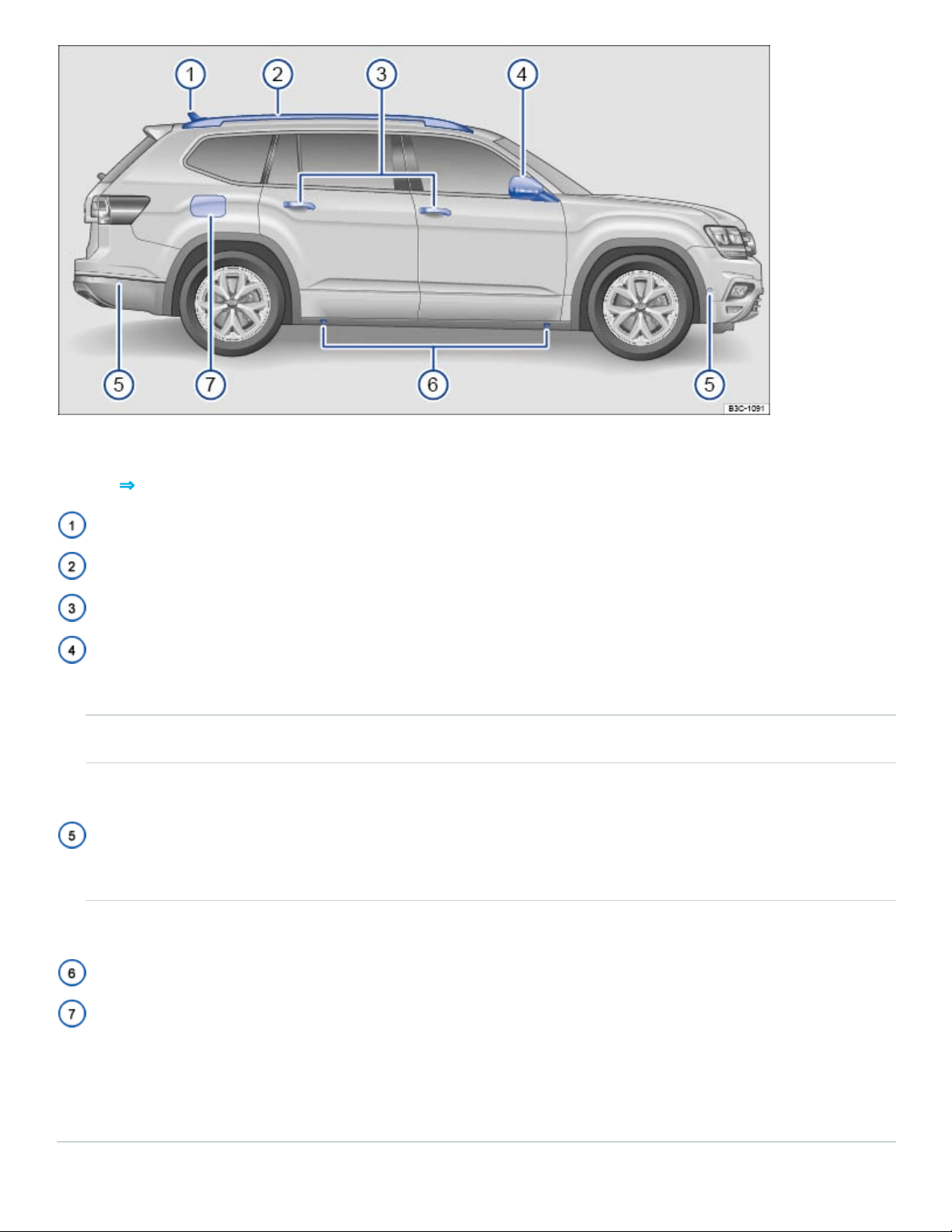
Fig.2Vehicle side overview.
Key to ⇒Fig.2 :
Roof antenna ⇒Consumer information
Roof rails (if equipped) ⇒Roof rack
Outside door handles ⇒Doors and power locking system
Outside mirror ⇒Mirrors
- Display for Blind Spot Monitor (if equipped) ⇒Blind Spot Monitor
- Area View camera (if equipped) ⇒Area View
- Additional turn signal light ⇒Lights
Sensors:
- Park Distance Control (PDC) (if equipped) ⇒Park Distance Control (PDC)
- Park Assist (if equipped) ⇒Park Assist
Lift points for the jack ⇒Lifting the vehicle with the vehicle jack
Fuel filler flap ⇒Refueling
Numbers ② through ⑥ are in the same place on the left side of the vehicle.
Rear view
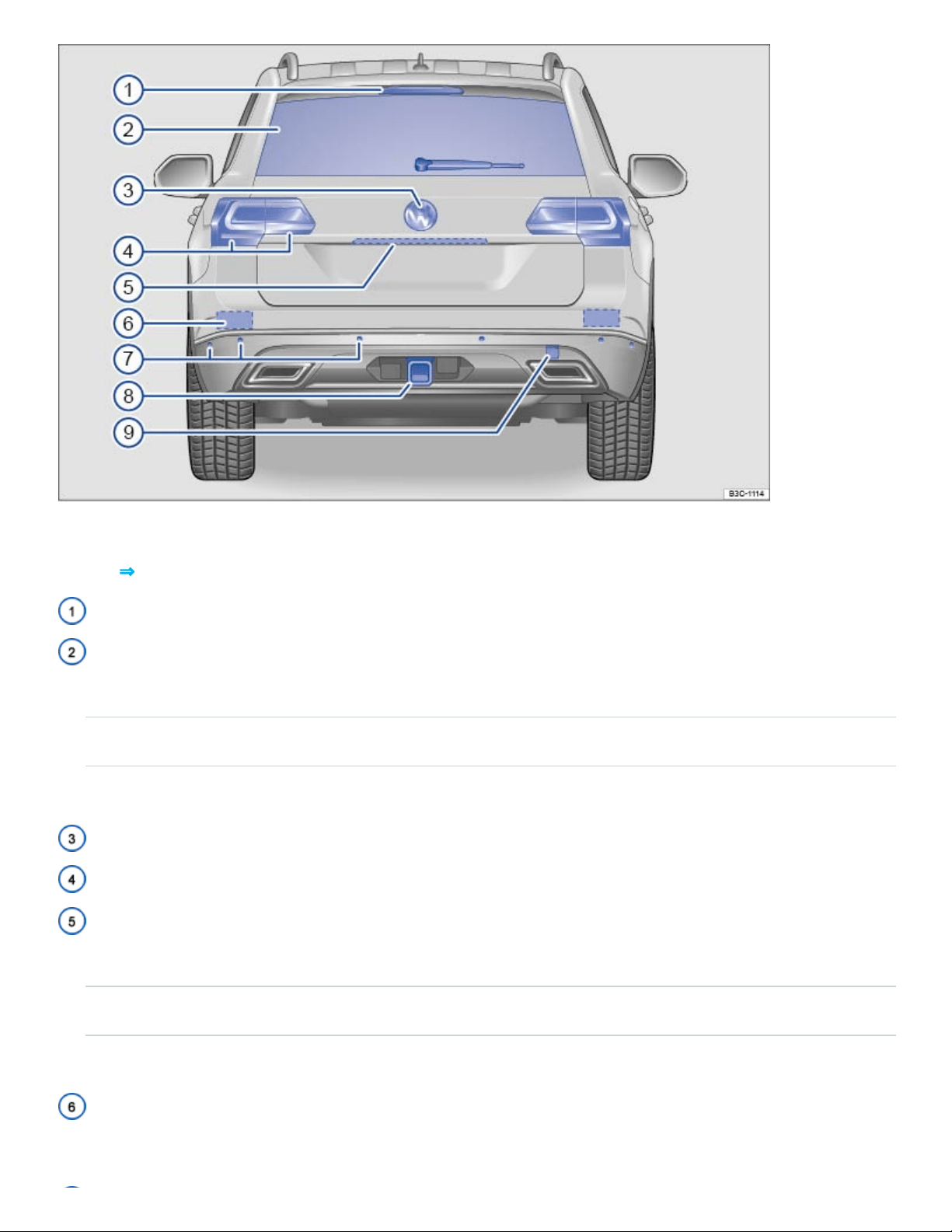
Fig.3Vehicle rear overview.
Key to ⇒Fig.3 :
High-mounted brake light
Rear window:
- Rear window defroster ⇒Climate control
- rear windshield wiper ⇒Windshield wipers and washer
- Roof antenna ⇒Consumer information
Volkswagen emblem
Taillights (on left and right) ⇒Lights ⇒Replacing light bulbs
Areas in the trunk lid:
- Button to open the trunk lid ⇒Power operation of the trunk lid
- Camera for Rear View and Area View ⇒Rear View Camera system , ⇒Area View
- License plate lights ⇒Replacing light bulbs
Sensors for the Blind Spot Monitor and Rear Traffic Alert (approximate location on left and right, if
equipped) ⇒Blind Spot Monitor and ⇒Rear Traffic Alert
Sensors (on left and right):
- Park Distance Control (PDC) (if equipped) ⇒Park Distance Control (PDC)
- Park Assist (if equipped) ⇒Park Assist
Trailer hitch preparation ⇒Trailer towing
Threaded hole for the rear towing eye behind a cover (if equipped) ⇒Towing
Driver door overview
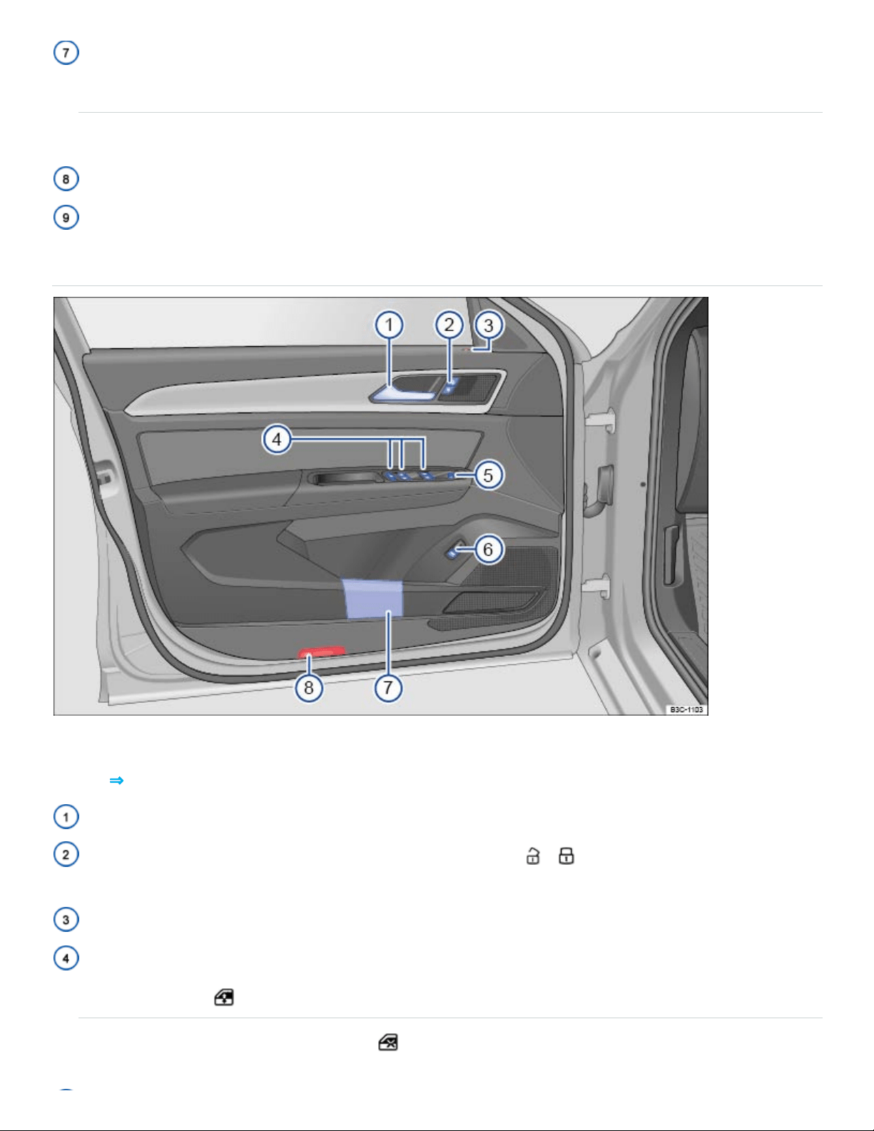
Fig.4Overview of the controls in the driver door.
Key to ⇒Fig.4 :
Door handle
Power locking button for locking and unlocking the vehicle – ⇒Doors and power locking sys‐
tem
Indicator light for the power locking system ⇒Doors and power locking system
Switches for operating the power windows: ⇒Power windows
- Power windows
- Safety switch for rear power windows
Knob for adjusting the outside mirrors: ⇒Mirrors
- Adjusting outside mirrors
- Outside mirror heating
- Fold outside mirrors
Switch for releasing the trunk lid
Storage compartment ⇒Storage areas
Light
Driver side overview
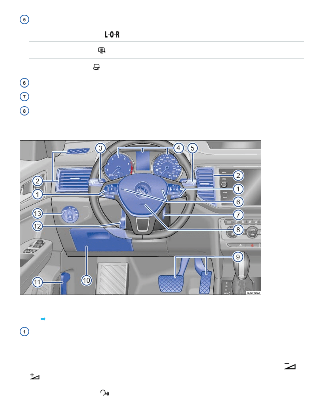
Fig.5Driver side overview
Key to ⇒Fig.5 :
Multi-function steering wheel controls ⇒Instrument cluster , ⇒Cruise control , ⇒Adaptive Cruise
Control (ACC) :
- Volume setting for radio, navigation system notifications (if applicable), or telephone calls –
- Voice control activation
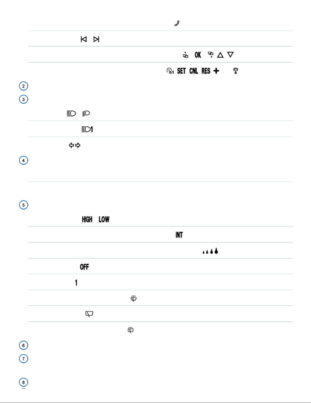
- Display Phone main menu or accept telephone calls
- Audio, navigation –
- Control buttons for the Volkswagen Information System – – , ,
- Cruise control or Adaptive Cruise Control buttons , , , , –-,
Air vents ⇒Climate control
Lever for ⇒Lights :
- High beams –
- Headlight flasher x
- Turn signals
Instrument cluster:
- Instruments and displays ⇒Instrument cluster
- Warning and Indicator lights ⇒Warning and indicator lights
Windshield wiper and washer lever ⇒Windshield wipers and washer :
- Windshield wiper –
- Intermittent operation for the front windshield wipers
- Interval settings for the wipers or sensitivity for the rain sensor (if equipped)
- Windshield wiper
- One-tap wiping x
- Automatic wipe/wash for windshield
- Rear window wiper
- Rear window automatic wipe/wash
Horn
Ignition switch (vehicles without Keyless Access) or location for the emergency start feature for
the Keyless Access system ⇒Starting and stopping the engine
Driver front airbag ⇒Airbag system
Pedals ⇒Pedals
Storage compartment ⇒Storage areas
Lever for releasing the engine hood ⇒In the engine compartment
Lever for the adjustable steering wheel ⇒Manually adjusting the steering wheel position
Headlight switch ⇒Lights :
- Off position - -
- Automatic headlights - - (if equipped)
- Parking lights and low beams
- Fog lights (if equipped).
Upper center console
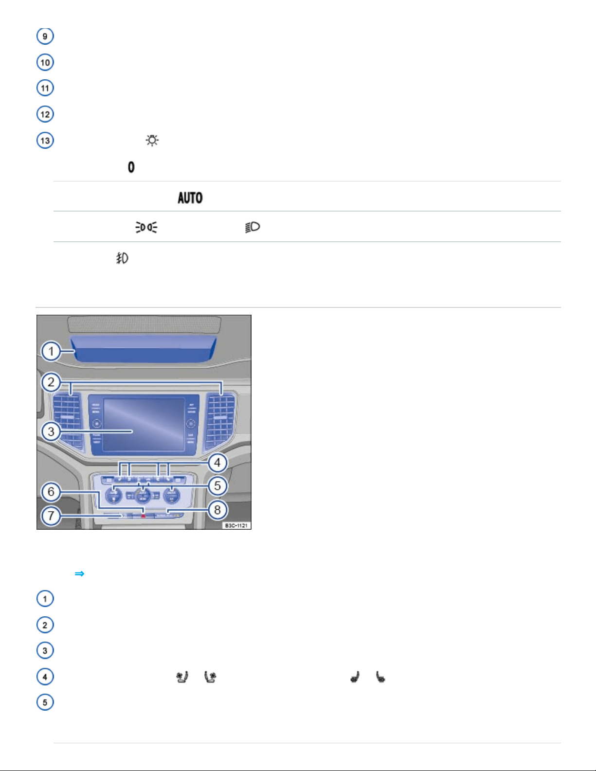
Fig.6Overview of the upper center console.
Key to ⇒Fig.6 :
Storage compartment ⇒Storage and equipment
Air vents ⇒Climate control
Infotainment system ⇒BookletInfotainment system,
Seat ventilation button or and seat heating buttons or ⇒Climate control
Controls:
- Manual air conditioning ⇒Climate control
- Climatronic ⇒Climate control
Button for the emergency flashers ⇒In an emergency
Buttons:
- Start-stop system ⇒Start-stop system
- Steering wheel heating ⇒Climate control
PASSENGERAIRBAG light (front airbag for front seat passenger) ⇒Airbag system
Lower center console
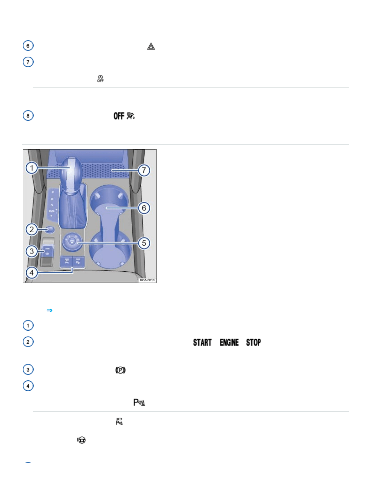
Fig.7Overview of the lower center console.
Key to ⇒Fig.7 :
Automatic transmission selector lever ⇒Automatic transmission
Starter button (for vehicles with Keyless Access) – – ⇒Starting and stopping
the engine
Electronic parking brake ⇒Electronic parking brake
Buttons for:
- Park Distance Control (PDC) ⇒Park Distance Control (PDC)
- Area View (if equipped)
- Park Assist ⇒Park Assist
Area for:
- Storage compartment ⇒Storage and equipment
- USB port, AUX-IN jack ⇒BookletInfotainmentsystem,
- 12 Volt socket ⇒Electrical sockets in the vehicle
Cup holders ⇒Cup holders
Rotary knob for 4MOTION Active Control ⇒4MOTION Active Control
Front passenger side overview
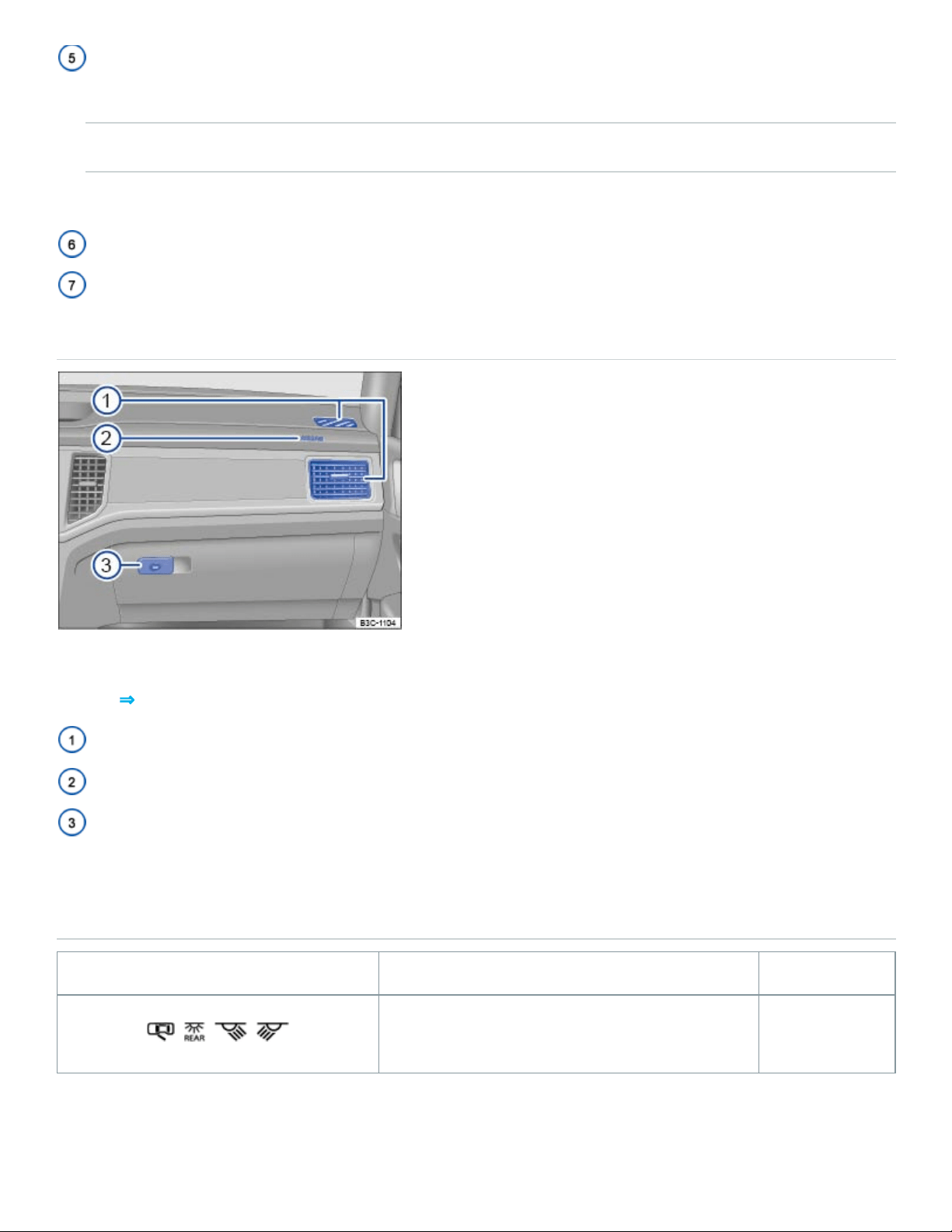
Fig.8Overview of the front passenger side.
Key to ⇒Fig.8 :
Air vent ⇒Climate control
Passenger front airbag location in the instrument panel (approximate) ⇒Airbag system
Opening handle for the lockable glove compartment ⇒Storage areas
Applicable only in the United States
Roof console
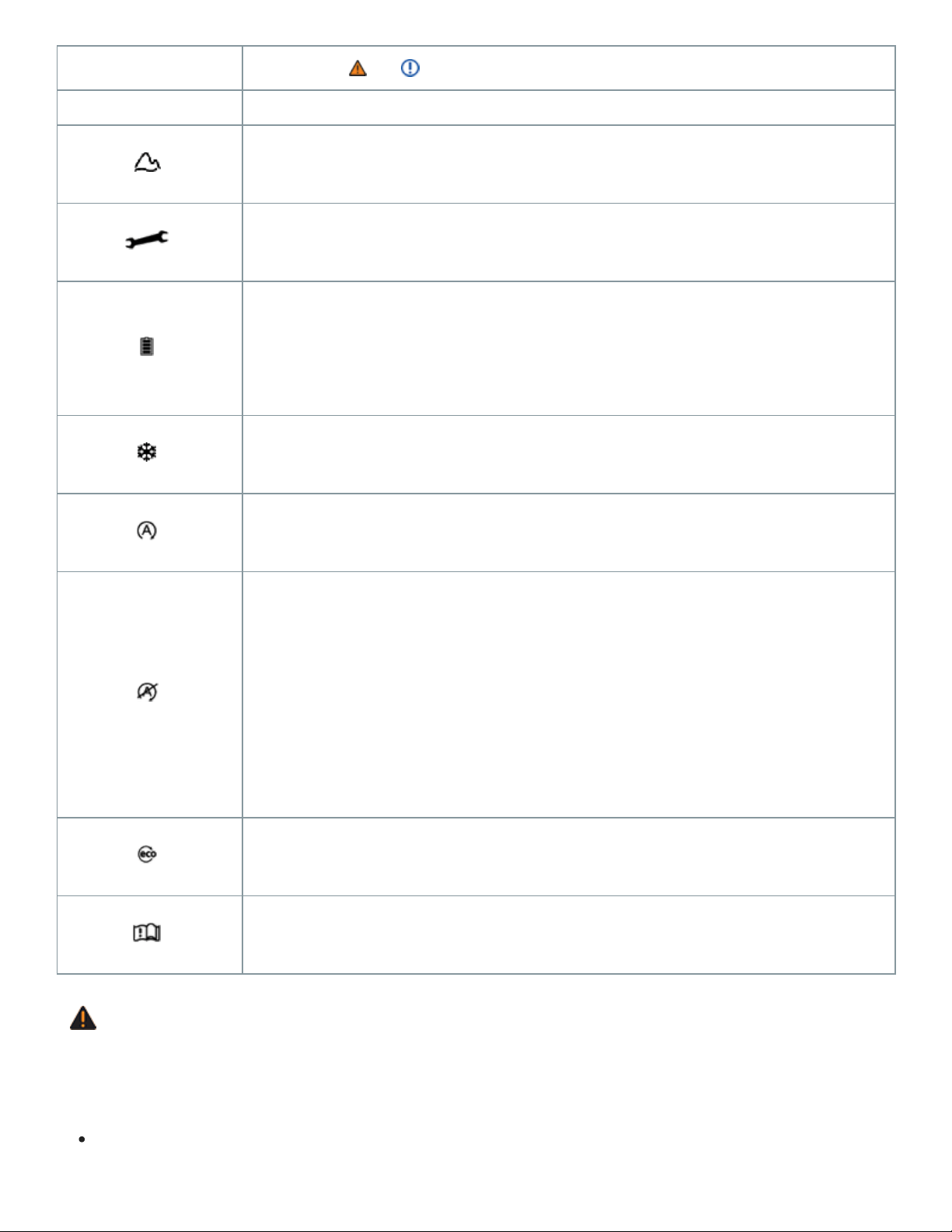
Symbol Meaning See
, , , Interior and reading lights. ⇒Lights
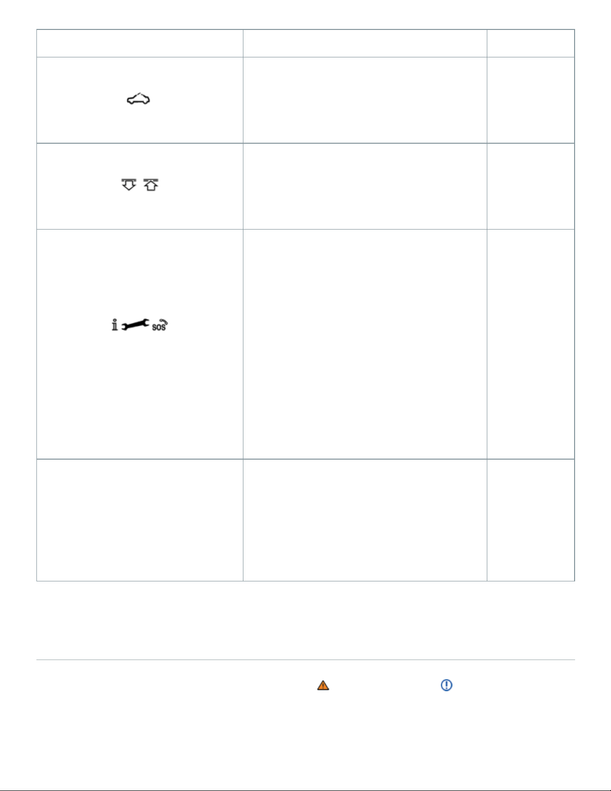
Symbol Meaning See
Power sunroof.
⇒Power
sunroof
, Buttons for sunshade.
⇒Power
sunroof
3-button module for vehicles with Car-Net
.
⇒VW Car-
Net Security
& Service:
Connecting
you and your
vehicle
123
Buttons for HomeLink Universal
Transmitter.
⇒HomeLink
Universal
Transmitter
Volkswagen Information System
Warning and indicator lights
Warning and indicator lights notify you of warnings ⇒ and malfunctions ⇒ , or tell you about cer‐
tain functions. Some warning and indicator lights come on when the ignition is switched on and
should go out when the engine is running or when the vehicle is moving.
®
®
®
®

Additional text messages appear in the instrument cluster of appropriately equipped vehicles to give
more information or prompt you to take certain actions ⇒Instrument cluster .
Depending on the vehicle options, a symbol may appear in the instrument cluster instead of a warn‐
ing light.
In addition, a warning chime or other acoustic warning sounds when certain warning and indicator
lights go on.
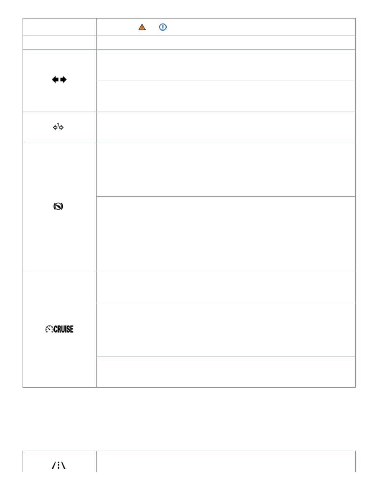
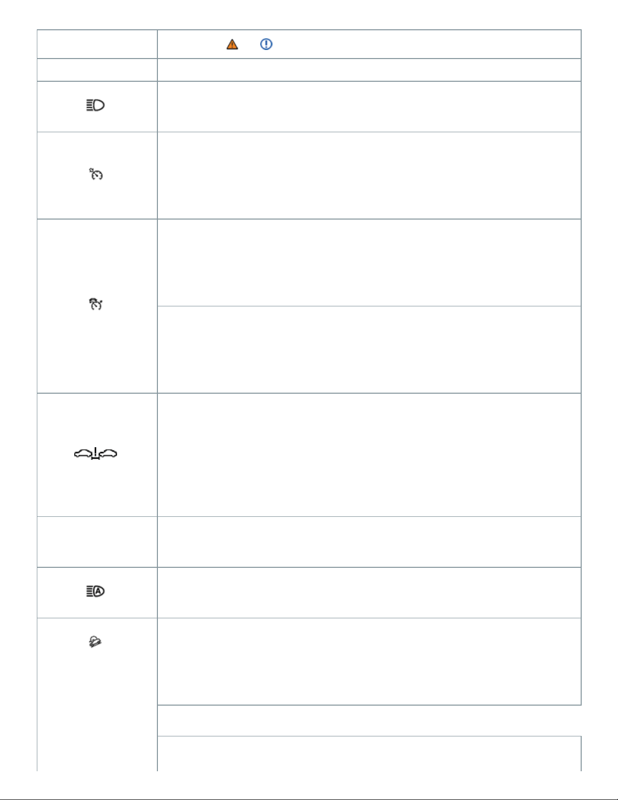
Symbol
Meaning ⇒ , ⇒
Central warning light: Read and follow the text messages in the instrument
cluster display.
Stop!
Parking brake engaged ⇒Using the electronic parking brake .
Stop!
Brake fluid level too low ⇒Brake fluid
OR: Brake system malfunction
OR: Together with the ABS indicator light or : ABS failure
⇒Braking assistance systems .
Stop!

Symbol
Meaning ⇒ , ⇒
Engine coolant level too low, engine coolant temperature too high, or engine
coolant system malfunction ⇒Engine coolant , ⇒Warning light and engine
coolant temperature gauge .
Stop!
Engine oil pressure too low ⇒Engine oil .
Stop!
Lights up: Steering system malfunction ⇒Tips and troubleshooting .
Stop!
Flashes: Electronic steering column lock malfunction ⇒Tips and trou‐
bleshooting .
Driver and/or passenger safety belts not buckled ⇒Safety belts .
Brake or take action to avoid the vehicle ahead! Front Assist Forward

Symbol
Meaning ⇒ , ⇒
Collision Warning (if equipped) ⇒Forward Collision Warning (Front Assist) .
OR: Pedestrian Monitoring system warning.
Brake! Depress brake pedal. ACC driver intervention warning ⇒Adaptive
Cruise Control (ACC) .
Alternator malfunction ⇒Vehicle battery .
Brake pads worn. Immediately contact an authorized Volkswagen dealer or
authorized Volkswagen Service Facility to have the brake pads checked
and, if necessary, replaced ⇒About the brakes .
Central caution light: Read and follow the text messages in the instrument
cluster display.
Lights up: ESC malfunction or ESC switched off by the system ⇒Braking

Symbol
Meaning ⇒ , ⇒
assistance systems .
OR: Together with : ABS malfunction.
OR: the vehicle battery has been reconnected.
Flashes: ESC or ASR is now active ⇒Braking assistance systems .
ASR manually switched off ⇒Braking assistance systems .
OR: ESC manually switched off.
OR: ESC Sport mode manually switched off ⇒Braking assistance sys‐
tems .
OR: Driving mode Off-road.
ABS malfunction ⇒Braking assistance systems .
Electronic parking brake malfunction ⇒Electronic parking brake .
One or more driving lights burned out ⇒Replacing light bulbs .

Symbol
Meaning ⇒ , ⇒
Light malfunction ⇒Vehicle lighting .
Lights up: Engine control malfunction ⇒Engine control and emission control
system .
Flashes: Misfire ⇒Engine control and emission control system .
Engine control malfunction ⇒Engine control and emission control system .
Engine speed (rpm) limited (if equipped, to help prevent overheating)
⇒Engine control and emission control system .
Lights up: Problem with the steering ⇒Tips and troubleshooting .
Flashes: Steering column not locked ⇒Tips and troubleshooting .
Lights up: Tire pressure too low ⇒Tires and wheels .
Flashes: Tire Pressure Monitoring System (TPMS) malfunction ⇒Tire
Pressure Monitoring System (TPMS) .
Rain sensor malfunction ⇒Windshield wipers and washer
Windshield wiper malfunction ⇒Windshield wipers and washer .

Symbol
Meaning ⇒ , ⇒
Not enough windshield washer fluid ⇒Windshield wipers and washer .
Fuel tank almost empty ⇒Refueling , ⇒Indicator lights and fuel gauge .
Lights up: Engine oil level too low ⇒Engine oil .
Flashes: Engine oil system malfunction ⇒Engine oil .
Airbag and safety belt pretensioner system malfunction ⇒Airbag system .
Passenger front airbag turned off (PASSENGERAIRBAG light)
⇒Airbag system .
Fuel filler cap not properly closed ⇒Indicator lights and fuel gauge
LaneAssist switched on, not active ⇒Engine oil .
Adaptive cruise control (ACC) currently not available ⇒Adaptive Cruise
Control (ACC) .
Transmission malfunction ⇒Automatic transmission .
Front Assist switched off (if equipped) ⇒Forward Collision Warning (Front
Symbol
Meaning ⇒ , ⇒
Assist) .
Turn signals, left or right ⇒Lights .
Emergency flashers switched on ⇒In an emergency .
Trailer turn signals ⇒Lights .
Lights up: Brake pedal not depressed ⇒Starting and stopping the engine ,
⇒Automatic transmission , ⇒Parking and maneuvering .
Flashes: The release button in the selector lever is not engaged ⇒Starting
and stopping the engine , ⇒Automatic transmission , ⇒Parking and ma‐
neuvering .
Cruise control is regulating the vehicle speed ⇒Cruise control .
OR: Adaptive Cruise Control (ACC) switched on ⇒Adaptive Cruise
Control (ACC) .
Flashes: vehicle is driving faster than the set speed warning ⇒Displays
LaneAssist is switched on and active ⇒Lane Keeping system (Lane
Symbol
Meaning ⇒ , ⇒
Assist) .
High beams switched on or headlight flashers in use ⇒High beams .
ACC is active. No vehicle has been detected ahead ⇒Adaptive Cruise
Control (ACC) .
When displayed in white: ACC active. Vehicle detected ahead ⇒Adaptive
Cruise Control (ACC) .
When displayed in grey: ACC not active. Vehicle detected ahead. System
switched on, does not regulate ⇒Adaptive Cruise Control (ACC) .
Increase the distance between your vehicle and the vehicle ahead.
Front Assist distance warning (if equipped) ⇒Driver warnings and
Autonomous Emergency Braking .
Cruise control malfunction ⇒Cruise control .
Light Assist high beam control switched on (if equipped) ⇒High beams .
When displayed in white: Hill Descent Control active ⇒Hill Descent
Control .
When displayed in grey: Hill Descent Control not active. System is turned
Symbol
Meaning ⇒ , ⇒
on, but not regulating ⇒Hill Descent Control .
Driving mode offroad or custom offroad active ⇒4MOTION Active Control .
Service reminder display ⇒Service reminder display .
Charge level of the mobile phone battery. Applies only to models with a fac‐
tory-installed mobile phone package ⇒BookletInfotainment system,.
Outside temperature colder than +39°F (+4°C) ⇒Displays .
Start-stop available. Automatic stop active ⇒Start-stop system .
Start-stop not available.
OR: Start-stop has automatically restarted the engine ⇒Start-stop
system .
Fuel-efficient vehicle status ⇒Displays .
Refer to the Owner's Manual.
WARNING
Failure to heed warning lights and instrument cluster text messages can result in a collision and
serious personal injury.
Never ignore warning lights or text WARNINGS.

Always stop the vehicle as soon as it is safe to do so.
Park the vehicle at a safe distance from moving traffic and where no part of the hot catalytic
converter and exhaust system can come into contact with flammable materials under the vehi‐
cle, such as dry grass, brush, spilled fuel, etc.
A broken down vehicle presents a high accident risk for itself and others. Switch on emer‐
gency flashers and set up a warning triangle to warn oncoming traffic.
Before opening the engine hood, always switch off the engine and let the engine cool down.
Always be very careful when working in the engine compartment, which is a potentially dan‐
gerous area in any motor vehicle and can cause serious personal injury ⇒In the engine com‐
partment .
NOTE
Failure to heed warning lights or text WARNINGS can result in vehicle damage.
Instrument cluster
Introduction to the subject
In this chapter you will find information on the following subjects:
⇒Instrument overview
⇒Volkswagen Digital Cockpit
⇒Tachometer
⇒Displays
⇒Instrument cluster menus
⇒Driving data (Multi-Function Display)
⇒Warning and information texts
⇒Setting the clock
⇒Indicator lights and fuel gauge
⇒Warning light and engine coolant temperature gauge
⇒Service reminder display
⇒Service menu (vehicles with the Volkswagen Digital Cockpit)
The vehicle is equipped either with an analog instrument cluster ⇒Instrument overview or a digital
instrument cluster (Volkswagen Digital Cockpit) ⇒Volkswagen Digital Cockpit .
Emergency starting and starting the engine with a very weak vehicle battery or after the vehicle bat‐
tery has been replaced may change or delete system settings (including time, date, and program‐
ming). Check the settings and correct as necessary once the vehicle battery has built up a sufficient
charge.
WARNING
Driving on today's roads demands the full attention of the driver at all times. Driver distraction
causes accidents, collisions and serious personal injury!
Never use the buttons in the instrument cluster while driving.
Adjust the settings in the instrument cluster or the infotainment system only when the vehicle
is standing still.
Applicable only in the United States
Instrument overview
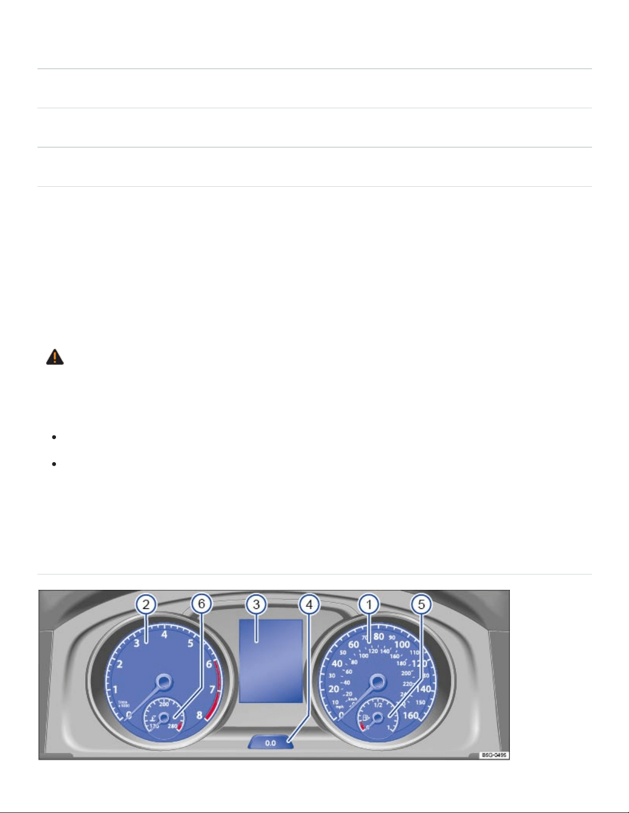
Fig.9Instrument cluster in the instrument panel.
Read and follow the introductory information and safety information first⇒ Introduction to the
subject
Instrument explanations ⇒Fig.9 :
Speedometer.
Tachometer (thousands of revolutions per minute when the engine is running) ⇒Tachometer .
Displays⇒Displays .
Reset, set, and display button⇒Driving data (Multi-Function Display) .
Fuel gauge⇒Indicator lights and fuel gauge , ⇒Refueling .
Engine coolant temperature gauge ⇒Engine coolant .
Volkswagen Digital Cockpit
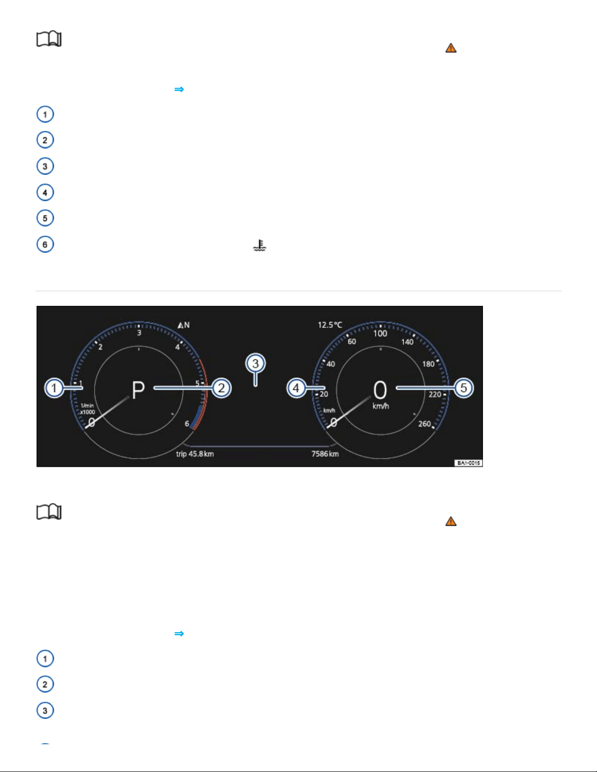
Fig.10Volkswagen Digital Cockpit in the instrument cluster.
Read and follow the introductory information and safety information first⇒ Introduction to the
subject
The Volkswagen Digital Cockpit is a digital instrument cluster with a high-resolution TFT color display.
In addition to standard gauges such as the tachometer and speedometer, you can choose from vari‐
ous information profiles to view more data.
Instrument explanations ⇒Fig.10 :
Tachometer (thousands of revolutions per minute when the engine is running) ⇒Tachometer .
Current gear or selector lever position⇒Automatic transmission .
Displays⇒Displays .

Speedometer Speed units can be changed in the vehicle settings menu ⇒Vehicle settings
menu .
Digital speed display.
Information profiles
You can choose between several display options under the menu Active Info Display in the vehicle
settings menu ⇒Vehicle settings menu in the Infotainment system.
The additional information is shown either in the middle of the dials or the dials are hidden and the in‐
formation is shown across the width of the display. You can choose the Classic display, or set the op‐
tions manually via the displays View 1, View 2, or View 3. Swipe up or down on the left or right cir‐
cles to set the information that is displayed on the left or right side of the Volkswagen Digital Cockpit,
respectively. The following information can be displayed:
Gear: Digital display of the current selector lever position or gear (shown in the Classic display).
Speed: Digital speed display (shown in the Classic display).
Economy : Current fuel economy is shown graphically and average fuel economy is shown
digitally.
Distance: Digital display of total distance traveled.
Travel time: Digital display of total driving time.
Assistance systems: Graphic displays relating to various driver assistance systems are shown
⇒Driver assistance systems .
Route guidance: For vehicles equipped with a factory-installed navigation system, arrow naviga‐
tion is displayed ⇒BookletInfotainment System,.
Range: Digital display of the estimated distance in miles (km) that the vehicle can go with the fuel
left in the tank the way you are currently driving.
Destination info: For vehicles equipped with a factory-installed navigation system, the remaining
driving time, distance to the destination and estimated time of arrival is displayed
⇒BookletInfotainment System,.
Compass: Digital compass display ⇒BookletInfotainment System,.
Elevation: Digital display of the current altitude above sea level.
Audio: Digital display of current audio information ⇒BookletInfotainment System,.
Acceleration: A graphic representation of acceleration is displayed.

Depending on equipment, the number and scope of the information profiles may vary.
Press the button to switch between the wide and standard displays.
Navigation map in the Volkswagen Digital Cockpit
On appropriately equipped vehicles, you can select the Navigation menu item in the Volkswagen
Information System to display the navigation map in the instrument cluster. Press the or the ar‐
row button to display options, then select Display map.
The map has two possible sizes. If you select the larger size, the Volkswagen Digital Cockpit dials will
be smaller. To select the map size:
Press the button on the multi-function steering wheel to switch between map sizes.
OR: Press the or the arrow button on the multi-function steering wheel to switch the
Enlarged map display on or off. Press the button on the multi-function steering wheel to con‐
firm your selection.
Navigation can only be shown on one display at a time. When you select the map display in the
Volkswagen Digital Cockpit, the map in the Infotainment system is not visible.
To display the map in the Infotainment system again, press the Infotainment button followed by
the Map function key.
WARNING
If the Volkswagen Digital Cockpit stops working properly or will not come on, you will not be able
to see important information such as vehicle speed, engine performance, warning lights. and text
warnings. Failure to see this information may result in the vehicle breaking down in traffic or result
in a collision and serious personal injury.
Always make sure that the Volkswagen Digital Cockpit is working before driving.
If you believe it is safe to do so, immediately take the vehicle to an authorized Volkswagen
dealer or authorized Volkswagen Service Facility.
Tachometer
Read and follow the introductory information and safety information first⇒ Introduction to the
subject

Tachometer
The beginning of the red zone at the end of the scale indicates maximum permissible engine rpm
(revolutions per minute) for all gears after the break-in period. Before the needle reaches the red
zone, select the next higher gear or selector lever positionD/S, or ease your foot off the accelerator
⇒ .
NOTE
To help prevent engine damage, always avoid high engine speeds, full throttle acceleration,
and heavy engine loads when the engine is cold.
To help prevent engine damage, the tachometer needle should only enter the red zone (warn‐
ing zone) briefly, for example, when accelerating rapidly.
Upshifting early into the next higher gear saves fuel and reduces engine noise.
Displays
Read and follow the introductory information and safety information first⇒ Introduction to the
subject
Possible displays in the instrument cluster
Open doors, engine hood, or trunk lid
Warning and information texts ⇒Warning and information texts
Odometer displays
Time ⇒Setting the clock
Radio and navigation information ⇒BookletInfotainment System,
Telephone information ⇒BookletInfotainment System,
Outside temperature
Compass display
Selector lever position ⇒Automatic transmission selector lever
Driving data and menus for different settings ⇒Driving data (Multi-Function Display)
Service reminder display ⇒Service reminder display

Speed warning
Start-stop system status information ⇒Start-stop system
Fuel-efficient driving display
Engine identification code
Driver personalization: user selection ⇒Driver Personalization
Open doors, hood, or trunk lid
The instrument cluster display indicates if any doors, the engine hood, or trunk lid are open once the
vehicle has been unlocked, and while the vehicle is moving. There may also be an audible warning
chime. Different models and equipment versions may have different displays.
Driver personalization
The instrument cluster display indicates which user profile is currently active for about 10seconds af‐
ter the ignition is switched on. During this time, you can switch from one user profile to another with
the arrow up and down buttons or on the multi-function steering wheel.
For vehicles equipped with the Volkswagen Digital Cockpit, the user profile affects which information
profile is shown ⇒Volkswagen Digital Cockpit , and also affects other vehicle settings ⇒Driver
Personalization .
You can adjust more settings for driver personalization in the Vehicle settings menu in the
Infotainment system ⇒Infotainment system operation and displays .
Odometer displays
The odometer at the bottom right corner of the instrument cluster display indicates the total distance
driven by the vehicle.
The trip odometer (trip) shows the distance driven since the last time the trip odometer was reset.
The last digit indicates 1/10mile (or 100meters, depending on the units selected).
For vehicles with an analog instrument cluster: Press the button in the instrument cluster
briefly ⇒Instrument overview to reset the trip odometer to0.
For vehicles with the Volkswagen Digital Cockpit: Reset the trip odometer via the Infotainment
system or the multi-function display ⇒Driving data (Multi-Function Display) or via the Service
menu in the Volkswagen Digital Cockpit ⇒Service menu (vehicles with the Volkswagen Digital
Cockpit) .

Outside temperature display
At outside temperatures below about +39°F (+4°C), a snowflake symbol appears in the display.
The symbol stays on until the outside temperature rises above +43°F (+6°C) ⇒ .
When the vehicle is not moving or when you are driving at very low speeds, the temperature dis‐
played may be slightly higher than the actual outside temperature.
The measurement range is from -49°F (-45°C) to +169°F (+76℃).
Compass display
On vehicles equipped with compass display, the current compass direction is indicated in the instru‐
ment cluster display when the ignition (or the navigation system, if equipped) is switched on.
Selector level position
The selector lever position is shown both on the side of the selector lever and in the instrument clus‐
ter. The respective gear may be shown in the instrument cluster display in Tiptronic mode
⇒Automatic transmission .
Speed warning
A display in the instrument cluster indicates when the set maximum speed has been exceeded.
The speed warning can also be set and changed in the Vehicle settings menu in the Infotainment
system when the ignition is switched on ⇒Infotainment system operation and displays .
Start-stop status display
The current status of the start-stop system is shown in the instrument cluster ⇒Start-stop system .
Fuel-efficient driving display
The instrument cluster display shows the symbol when the vehicle is being driven in a fuel-efficient
manner.
Engine identification code
Press and hold the button in the instrument cluster for about 15seconds to display the vehicle's
engine identification code. You must do this when the doors are closed, the ignition is on, but the en‐
gine is not running ⇒Volkswagen Digital Cockpit .
®

WARNING
Failure to heed warning lights and instrument cluster text messages can result in a collision and
serious personal injury.
Never ignore warning lights or text WARNINGS.
Always stop the vehicle as soon as it is safe to do so.
Park the vehicle at a safe distance from moving traffic and where no part of the hot catalytic
converter and exhaust system can come into contact with flammable materials under the vehi‐
cle, such as dry grass, brush, spilled fuel, etc.
A broken down vehicle presents a high accident risk for itself and others. Switch on emer‐
gency flashers and set up a warning triangle to warn oncoming traffic.
WARNING
Roads and bridges may be dangerously icy even if the outside air temperature is above freezing.
If you use the outside temperature display to tell you about frost conditions, remember that
roads can even ice over at temperatures above +39°F (+4°C). Always remember: even if the
snowflake symbol is not displayed, there could still be black ice on the road.
Never rely exclusively on the outside temperature display.
NOTE
Failure to heed warning lights or text WARNINGS can result in vehicle damage.
The instrument cluster displays and their arrangement may vary depending on the vehicle model
and engine. For displays without warning and information messages, malfunctions are only sig‐
naled with indicator lights.
Depending on vehicle equipment, some settings and displays may also appear in the
Infotainment system.
Instrument cluster menus

Read and follow the introductory information and safety information first⇒ Introduction to the
subject
The following list shows how the Volkswagen Information System menus in the instrument cluster dis‐
play are structured. The size and layout of the Volkswagen Information System menu depends on the
vehicle electronics and the vehicle equipment.
Certain menus may only be displayed while the vehicle is completely stopped.
Driving data⇒Driving data (Multi-Function Display)
Assist systems⇒Driver assistance systems
Lane Assist
Blind Spot Monitor
Rear Traffic Alert
Front Assist
Navigation ⇒BookletInfotainment System,
Views ⇒Volkswagen Digital Cockpit
Audio ⇒BookletInfotainment System,
Telephone ⇒BookletInfotainment System,
Vehicle status
Only in vehicles with Volkswagen Digital Cockpit.
Driving data (Multi-Function Display)
Read and follow the introductory information and safety information first⇒ Introduction to the
subject
When the ignition is on, the Driving data menu provides a variety of travel and fuel consumption
data. The driving data is displayed in the instrument cluster ⇒Instrument cluster menus .
Switching between the displays
Use the arrow up and down buttons ( and ) on the right side of the steering wheel ⇒Fig.17 .
Trip memories
1)
1)

The display has 3 automatic memories:
Since start
Since refuel
Extend. period
The currently selected memory is shown in the display.
The trip memories are in addition to the trip odometer, which is displayed in the bottom part of the in‐
strument cluster ⇒Vehicle settings menu ⇒Odometer displays .
On appropriately equipped vehicles, the driving data for the trip memories can also be viewed in the
Infotainment system by pressing the button followed by the Selection function key ⇒Vehicle set‐
tings menu .
Press the button on the multi-function steering wheel to toggle between the 3memories when the
ignition is on.
For vehicles with the Volkswagen Digital Cockpit: You can view a summary of driving data for the 3
memories by selecting the Trip information option in the Driving data menu.
Since start trip memory
The memory accumulates and stores information about distance driven and fuel consumption from
the time the ignition was switched on until the time it was switched off.
If the ignition stays off for 2hours or more, stored information is automatically deleted. If the trip is
continued within 2hours after the ignition was switched off, the memory continues to accumulate and
store information after the ignition is switched on again.
Extend. period trip memory
Depending on the instrument cluster version, the memory displays and stores the accumulated driv‐
ing and fuel consumption data of any number of single trips up to a total driving time of either
19hours and 59minutes or 99hours and 59minutes, and up to a total distance of either 1,999km or
9,999km. If one of the maximum values is exceeded, then the memory is automatically cleared and
starts again from 0.
Since refuel trip memory
1)

The memory accumulates and stores information about distance driven and fuel consumption from
the time the vehicle is refueled. The memory is deleted automatically during refueling.
Manually erasing a trip memory
Select either the Since start or the Extended period memory to be erased. The Since refuel
memory cannot be erased.
Press and hold the button on the multi-function steering wheel for about 2seconds.
Enabling and disabling displays
You can set which displays should appear in the instrument cluster in the Vehicle settings menu in
the Infotainment system ⇒Infotainment system operation and displays . The units in which data is
displayed can also be changed.
For vehicles with the Volkswagen Digital Cockpit: You can customize other instrument cluster settings
via the Active Info Display menu in the Infotainment system by pressing the button followed by
the Selection function keys.
Storing speed for the speed warning
Select the Speed warning display.
Press the button on the multi-function steering wheel to save the current speed and to switch
on the warning.
If necessary, set the desired speed within about 5seconds with the or buttons on the multi-
function steering wheel. Then press the button on the multi-function steering wheel a second
time or just wait a few seconds. The speed is saved and the warning is switched on.
To switch off, press the button on the multi-function steering wheel. The set speed is deleted.
You can also set the speed warning in the Vehicle settings menu in the Infotainment system
⇒Vehicle settings menu .
Certain settings are automatically saved by the driver personalization feature ⇒Driver
Personalization .
May differ depending on the instrument cluster version.
Warning and information texts
1)

Read and follow the introductory information and safety information first⇒ Introduction to the
subject
The status of various vehicle functions and components is monitored when the ignition is switched on
and while driving. Malfunctions are indicated by red and yellow warning symbols with text messages
in the instrument cluster display (⇒Warning and indicator lights ). In some cases, they may also be
signaled acoustically. The display can vary depending on the instrument cluster model.
Additionally, current malfunctions can be manually displayed under the menu Vehicle status or
Vehicle.
Priority1 warning message (red)
A symbol flashes or lights up – sometimes with acoustic warnings Stop!⇒ .
Check the malfunction and take corrective action. Contact an authorized Volkswagen dealer or an au‐
thorized Volkswagen Service Facility for assistance if necessary.
Menus cannot be accessed when a priority1 warning message is displayed. The warning message
will turn off automatically after a few seconds. You can confirm and turn off some warning messages
by pressing the button on the multi-function steering wheel.
Priority2 warning message (yellow)
A symbol flashes or lights up continuously – sometimes with acoustic warnings.
Malfunctions or low operating fluid levels may cause vehicle damage and vehicle breakdown ⇒ .
Check the malfunction as soon as possible. Contact an authorized Volkswagen dealer or an autho‐
rized Volkswagen Service Facility for assistance if necessary.
Information texts
Information text provide information about various vehicle situations.
WARNING
Failure to heed warning lights and instrument cluster text messages can result in a collision and
serious personal injury.
Never ignore warning lights or text WARNINGS.
Always stop the vehicle as soon as it is safe to do so.
Whenever stalled or stopped for repair, move the vehicle a safe distance off the road, stop the
engine, turn on the emergency flashers, and use other warning devices to warn approaching
traffic.
Never park the vehicle in areas where the hot catalytic converter and exhaust system can
come into contact with dry grass, brush, spilled fuel, oil, or other material that can catch fire.
A broken down vehicle presents a high accident risk for itself and others. Switch on emer‐
gency flashers and set up a warning triangle to warn oncoming traffic.
NOTE
Failure to heed warning lights or text WARNINGS can result in vehicle damage.
If there are multiple warning messages, the symbols are displayed for several seconds in order of
importance. The symbols are displayed until the cause has been corrected.
If warning messages are displayed when the ignition is switched on, it may not be possible to ad‐
just some settings as described, or the information display may appear differently. If this happens,
take the vehicle to an authorized Volkswagen dealer or an authorized Volkswagen Service
Facility for assistance.
Setting the clock
Read and follow the introductory information and safety information first⇒ Introduction to the
subject
Setting the time in the Infotainment system
Press the Infotainment button.
Tap the Vehicle and function keys.
Select the Time and Date menu to set the time.
Setting the time in the analog instrument cluster
If a vehicle status message or the vehicle icon is displayed, push the button on the right side of
the multi-function steering wheel.
To set the time, press and hold the button in the instrument cluster until the word Time ap‐
pears in the display or ⇒Instrument overview . If the ignition is switched off, the doors must be
closed.
Release the button. The time is shown in the instrument cluster display and the hour setting is
highlighted.
Press the button repeatedly until the correct hour is displayed. Press and hold the button to
scroll through quickly.
Once you have set the hour, release the button and wait a few seconds until the minutes display is
highlighted.
Press the button repeatedly until the correct minutes are displayed. Press and hold the button
to scroll through quickly.
Release the button to finish setting the clock.
Setting the time in the Volkswagen Digital Cockpit
Range must be displayed in the Driving data menu in the instrument cluster display
⇒Volkswagen Digital Cockpit .
Press and hold the button on the multi-function steering wheel until the Service menu appears
in the instrument cluster display ⇒Service menu (vehicles with the Volkswagen Digital Cockpit) .
Select the Time submenu.
Set the time using the or buttons on the multi-function steering wheel.
Indicator lights and fuel gauge
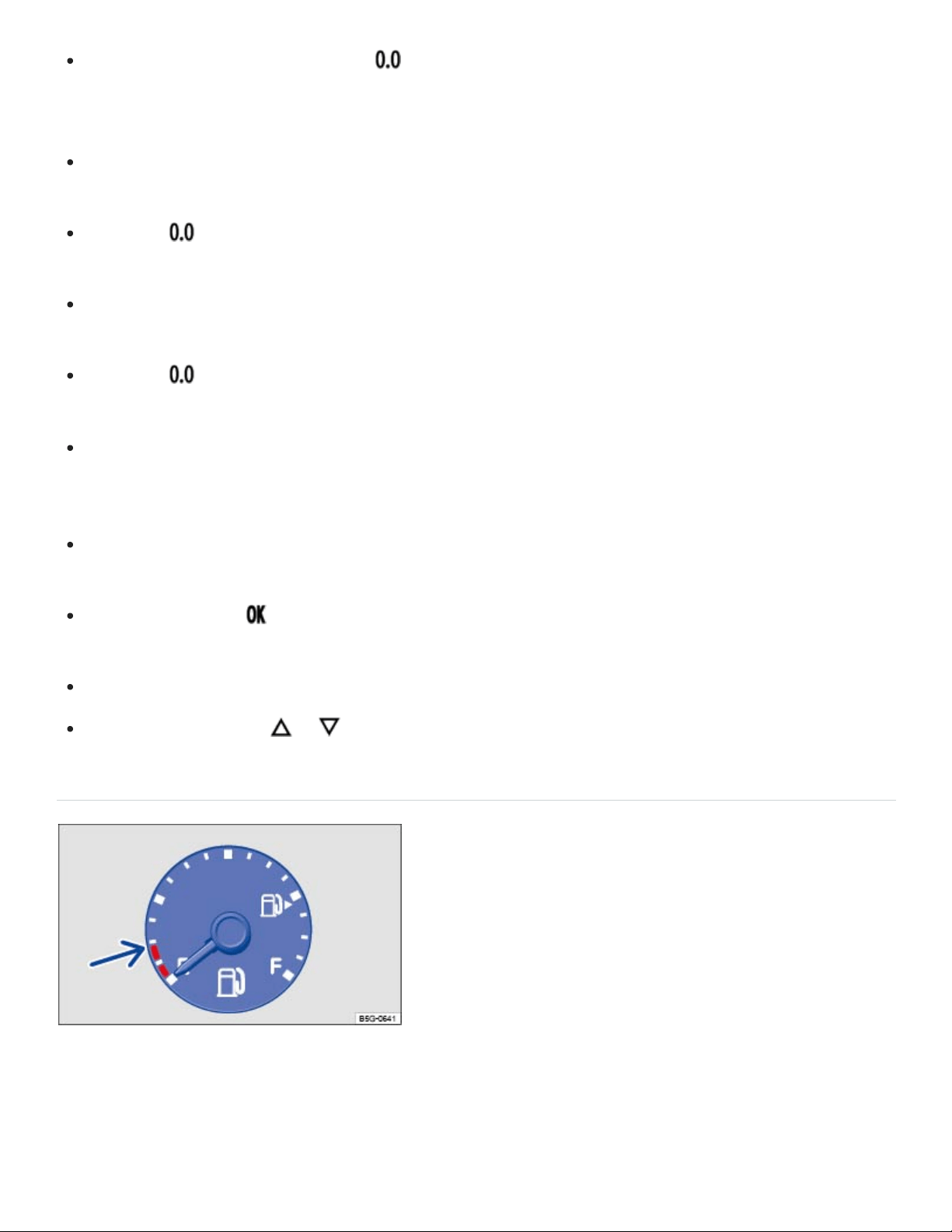
Fig.11In the instrument cluster: Fuel gauge.
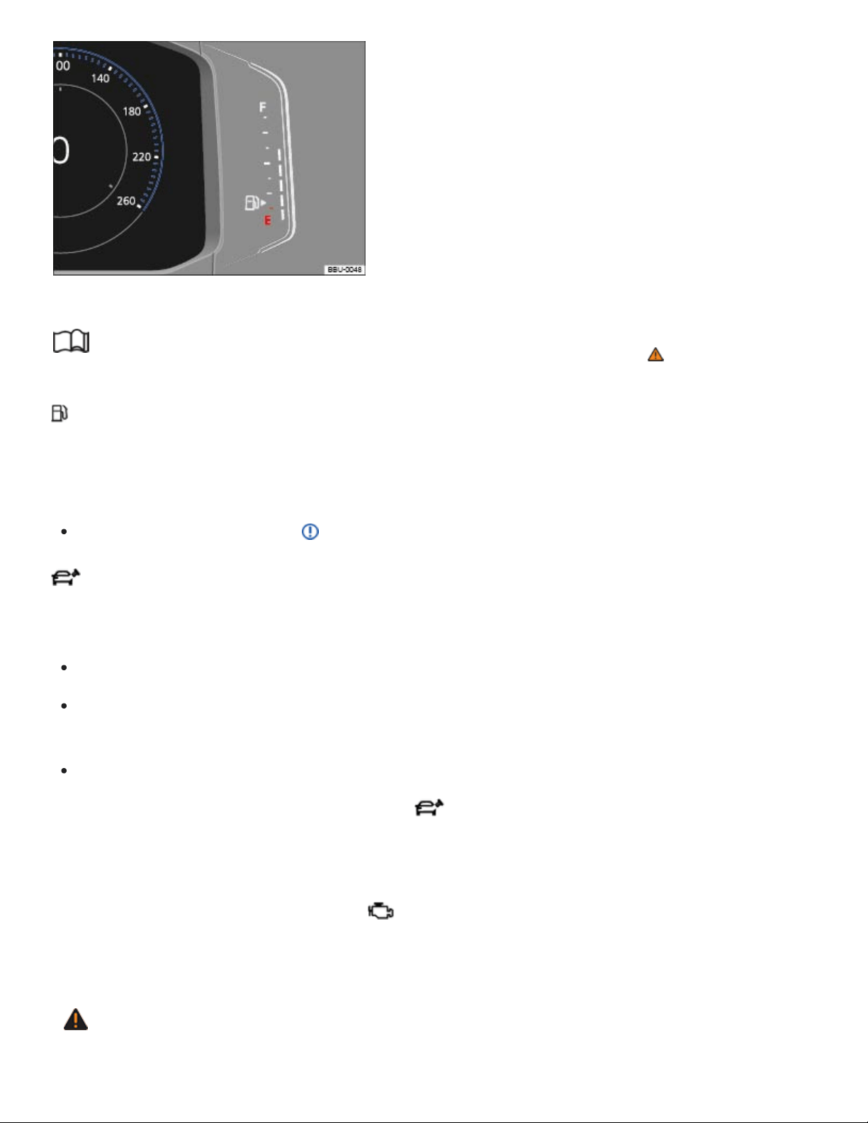
Fig.12Volkswagen Digital Cockpit: Fuel gauge
Read and follow the introductory information and safety information first⇒ Introduction to the
subject
Fuel tank almost empty
The yellow indicator light comes on. The vehicle is running on reserve (red area indicated in
⇒Fig.11 or ⇒Fig.12 ) ⇒Fuel and emission control system , ⇒Fuel capacities .
Refuel as soon as possible ⇒ .
Fuel filler cap not properly closed
The yellow indicator light comes on.
Stop the vehicle in a safe place and switch off the engine and the ignition.
Open the fuel filler flap and take the fuel filler cap off the filler neck. Then put the fuel filler cap
back on the filler neck and screw it on clockwise until you clearly hear a clicking sound.
Close the fuel filler flap.
After switching on the ignition, the indicator light may stay on or the text message may still ap‐
pear in the instrument cluster display, even if the fuel filler cap is now properly closed. This is normal
and no reason to take your vehicle in for service.
If, however, the malfunction indicator light also comes on, drive to your nearest authorized
Volkswagen dealer or authorized Volkswagen Service Facility and have the fuel system and the en‐
gine checked.
WARNING
Driving with a fuel tank that is almost empty can lead to stalling in traffic, a collision, and serious
personal injuries.
When the fuel tank is almost empty, fuel supply to the engine can be interrupted, especially
when driving over bumps, across slopes, and up and down hills.
Steering and braking assistance as well as ESC and related systems will not work if the en‐
gine sputters or stalls due to lack of fuel.
Always refuel when the tank is 1/4full to reduce the risk of running out of fuel and stalling in
traffic.
NOTE
Failure to heed warning lights or text WARNINGS can result in vehicle damage.
Never drive until the fuel tank is completely empty. The irregular fuel supply can cause the en‐
gine to misfire. This allows unburned fuel to get into the exhaust system and damage the cat‐
alytic converter.
The small arrow next to the gas pump symbol in the fuel gauge shows the side of the vehicle with
the fuel filler flap.
Applicable only in the United States
Warning light and engine coolant temperature gauge
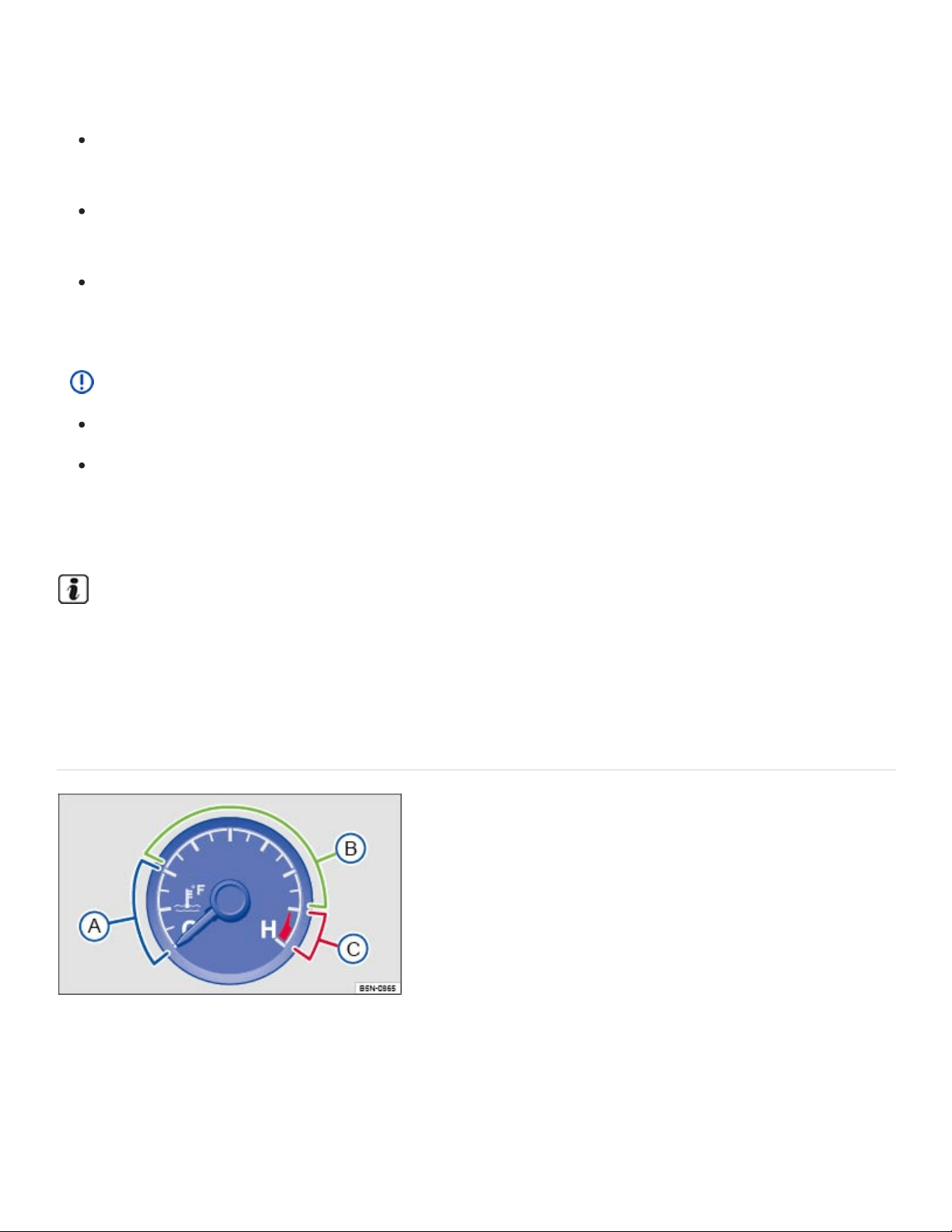
Fig.13Engine coolant temperature gauge in the instrument cluster.
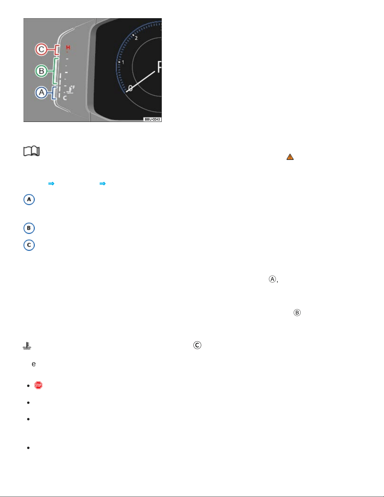
Fig.14in the Volkswagen Digital Cockpit: Engine coolant temperature gauge.
Read and follow the introductory information and safety information first⇒ Introduction to the
subject
Key to ⇒Fig.13 and ⇒Fig.14 :
Cold range. Do not drive at high engine speeds or with heavy engine loads until the engine
warms up.
Normal temperature range.
Warning zone. The display may also move into the warning area when the engine is working
hard, especially at high ambient temperatures.
If the needle in the engine coolant temperature gauge is in the cold range
Ⓐ
, the engine has not
reached operating temperature. High engine speeds and heavy engine loads should be avoided.
Under normal driving conditions, the needle should be in the middle of the gauge
Ⓑ
. The temperature
may go higher when the engine is working hard, especially in hot weather.
Flashes when the temperature needle is in area
Ⓒ
The engine coolant temperature is too high.
Stop! Pull off the road and stop as soon as you can do so safely.
Stop the engine and let it cool down until the temperature needle is in the normal range again.
Check the engine coolant level and add engine coolant if needed ⇒Checking engine coolant level
and topping off .
If the engine coolant level is correct or the problem continues after adding coolant and driving a
short distance, do not drive any farther. Contact the nearest authorized Volkswagen dealer or
authorized Volkswagen Service Facility.

If the coolant level is correct, the overheating may be caused by a radiator fan fault. Check the
fuses and replace as necessary ⇒Replacing fuses .
Flashes when the temperature needle is in area
Ⓑ
The engine coolant level is too low or there is a coolant system malfunction.
Stop! Pull off the road and stop as soon as you can do so safely.
Check the engine coolant level after the engine has cooled down and add engine coolant if low
⇒Engine coolant .
If the engine coolant level is correct but the warning light does not go out OR if the needle goes
into the red warning zone
Ⓒ
, do not drive any farther! Contact an authorized Volkswagen dealer
or authorized Volkswagen Service Facility for assistance.
WARNING
Failure to heed warning lights and instrument cluster text messages can result in a collision and
serious personal injury.
Never ignore warning lights or text WARNINGS.
Always stop the vehicle as soon as it is safe to do so.
Service reminder display
Fig.15In the instrument cluster display: Example of the service reminder when a service is due.
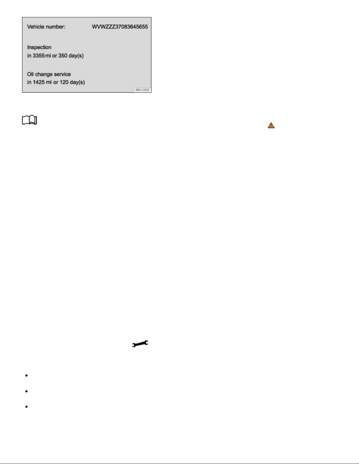
Fig.16In the Infotainment system display: Example of the service reminder.
Read and follow the introductory information and safety information first⇒ Introduction to the
subject
The maintenance service reminder is shown in the instrument cluster display ⇒Fig.15 and in the
Infotainment system ⇒Fig.16 . Versions and displays can vary depending on the instrument cluster
or the Infotainment system version equipped with the vehicle.
For information on maintenance intervals, please see the ⇒BookletWarranty and Maintenance,.
For vehicles with time- or distance driven-dependent service, only fixed service intervals are
displayed.
Service reminder
If service is due in the near future, a service reminder is displayed when the ignition is switched on.
The number of miles (km) and amount of time shown correspond to the maximum number of miles
(km) or maximum time that can still be driven before the next service.
Service event
For a scheduled oil service or a scheduled inspection there is an audible chime when the ignition
is switched on. The wrench symbol also appears for several seconds in the instrument cluster
display along with one of the following messages ⇒Fig.15 :
Oil service now!
Inspection now!
Oil service and inspection now!
Viewing service message

You can view service information ⇒Fig.16 in the Vehicle settings menu in the Infotainment system
⇒Vehicle settings menu .
Press and hold the button in the instrument cluster until the word Service appears in the dis‐
play ⇒Instrument overview .
Release the button. The current service message appears in the display for a few seconds.
Range must be displayed in the Driving data menu in the instrument cluster display
⇒Volkswagen Digital Cockpit .
Press and hold the button on the multi-function steering wheel for about 4seconds and then
release. The Service menu appears in the instrument cluster display. For more information, see
⇒Service menu (vehicles with the Volkswagen Digital Cockpit) .
Resetting the service reminder display (analog instrument cluster)
If the service was not performed by an authorized Volkswagen dealer or an authorized Volkswagen
Service Facility, the service reminder can be reset as follows:
Switch off the ignition.
Press and hold the button in the instrument cluster ⇒Instrument overview .
Switch on the ignition.
Release the button.
If one of the following messages appears in the display:
Reset oil service?
Do you really want to reset inspection?
Confirm the request by pressing the button in the instrument cluster. A confirmation message
appears in the display when the service reminder has been reset.
Do not reset the service reminder between service intervals; otherwise, incorrect information will
be displayed.
Service menu (vehicles with the Volkswagen Digital Cockpit)
Read and follow the introductory information and safety information first⇒ Introduction to the
subject

For vehicles with the Volkswagen Digital Cockpit, there is a Service menu.
Opening the Service menu
Range must be displayed in the Driving data menu in the instrument cluster display ⇒Volkswagen
Digital Cockpit .
Press and hold the button on the multi-function steering wheel for about 4seconds and then re‐
lease. The Service menu appears in the instrument cluster display.
Resetting oil change service
Select the Reset oil change menu item and follow the instructions in the instrument cluster display.
Resetting the inspection interval display
Select the Reset inspection menu item and follow the instructions in the instrument cluster display.
Resetting driving data
Select the Reset trip menu item and follow the instructions in the instrument cluster display to reset
the desired value.
Engine identification code
Select the Engine code menu item. The engine identification code appears in the instrument cluster
display.
Setting the time
Select the Time menu item and set the correct time with the arrow buttons or .
Viewing Volkswagen Digital Cockpit copyright information
Select the Copyright menu item to view more information.
Using the instrument cluster menus
Introduction to the subject
In this chapter you will find information on the following subjects:
⇒Operation with the multi-function steering wheel
⇒Driver Assistance systems button
The number of menus and information in the instrument cluster display depends on the electronics
and equipment on the vehicle.
An authorized Volkswagen dealer or an authorized Volkswagen Service Facility may be able to add or
modify functions depending on your vehicle's equipment.
As long as a priority1 warning message is displayed, no menus can be accessed. To display menus,
acknowledge the warning by pressing the button on the multi-function steering wheel ⇒Fig.17 .
WARNING
Driving on today's roads demands the full attention of the driver at all times. Driver distraction
causes accidents, collisions and serious personal injury!
Never access menus when the vehicle is moving.
Emergency starting and starting the engine with a very weak vehicle battery or after the vehicle
battery has been replaced may change or delete system settings (including time, date, and pro‐
gramming). Check the settings and correct as necessary once the vehicle battery has built up a
sufficient charge.
Operation with the multi-function steering wheel
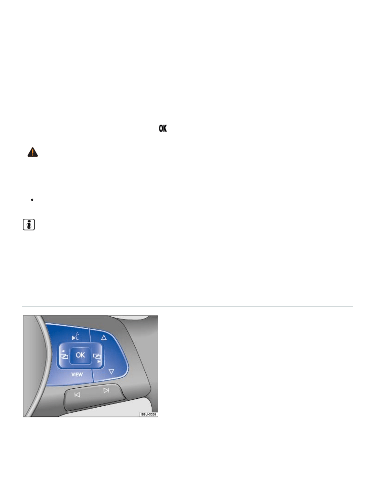
Fig.17Right side of the multi-function steering wheel: Controls for the menus and information in the
instrument cluster display.

Read and follow the introductory information and safety information first⇒ Introduction to the
subject
Accessing the instrument cluster menus and information displays
Switch on the ignition.
Driver personalization: Select user.
If a message or the vehicle icon is displayed, push the button (⇒Fig.17 ) on the right side of
the multi-function steering wheel until a main menu appears in the instrument cluster display. For
a list of main menus, see ⇒Instrument cluster menus .
Push buttons or to move to another main menu, and push the arrow up and down buttons
and to navigate within the current main menu.
To open the menu or information display shown in the selection menu, press the button on the
multi-function steering wheel or wait until the menu or information display opens automatically after a
few seconds.
Selecting a setting
Use the arrow up and down buttons or on the multi-function steering wheel ⇒Fig.17 to navi‐
gate through the available options. A frame may appear around the selected option. Push the but‐
ton to select a setting.
Returning to the main menu
Press the or button ⇒Fig.17 .
VIEW button
For vehicles with an analog instrument cluster: Press the button to switch between the cur‐
rent and previously selected menus.
For vehicles with a Volkswagen Digital Cockpit: Press the button to switch between the wide
and standard displays ⇒Volkswagen Digital Cockpit .
If warning messages are displayed when the ignition is switched on, it may not be possible to ad‐
just some settings as described, or the information display may appear differently. If this is the
case, take the vehicle to an authorized Volkswagen dealer or an authorized Volkswagen Service
Facility for assistance.
Driver Assistance systems button
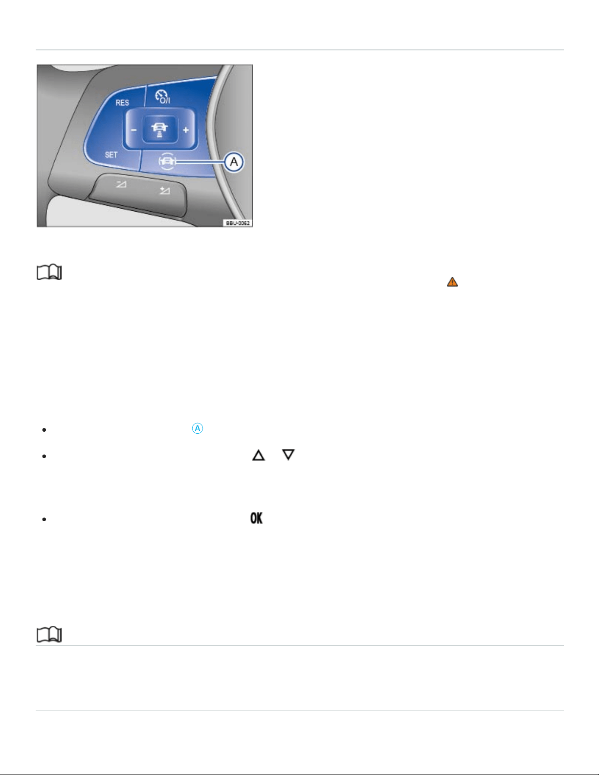
Fig.18On the multi-function steering wheel: Driver assistance systems button.
Read and follow the introductory information and safety information first⇒ Introduction to the
subject
Your vehicle may have a driver assistance systems button on the multi-function steering wheel, which
lets you switch some driver assistance systems on or off in the Assist systems menu ⇒Instrument
cluster menus .
Switching individual driver assistance systems on or off
Press the button ⇒Fig.18
Ⓐ
to open the Assist systems menu.
Using the arrow up and down buttons or on the multi-function steering wheel, select the
driver assistance system (for example, Lane Assist, if equipped). A check mark indicates if the se‐
lected driver assistance system is switched on.
Confirm the selection by pressing the button on the multi-function steering wheel.
You can also switch driver assistance systems on and off in the Vehicle settings menu in the
Infotainment system ⇒Infotainment system operation and displays .
Infotainment system operation and displays
Introduction to the subject
In this chapter you will find information on the following subjects:
⇒Vehicle settings menu
⇒Driver Personalization
General information on operating the unit
The following section contains information on the settings that can be adjusted in the Vehicle set‐
tings menu. You can find information on operating the Infotainment system as well as warning and
safety instructions in a separate manual. See ⇒BookletInfotainment System,.
Some Infotainment features can only be accessed and operated when the vehicle is standing still and
the automatic transmission selector lever is in Park (P).
Vehicle settings and information
After pressing the button followed by the Vehicle function key, you can tap the corresponding
function key on the Infotainment screen to display information or adjust the following settings:
Selection (Vehicle information)
Energy consumers
Driving data (Since start, extend. period, since refuel) ⇒Driving data (Multi-Function
Display)
Think Blue. Trainer.
Vehicle status (Current warning and information messages)
Offroad⇒Offroad display
Radio or Media (Radio station or media selection) ⇒BookletInfotainment System,
(Vehicle settings) ⇒Vehicle settings menu
WARNING
Driving on today's roads demands the full attention of the driver at all times. Driver distraction
causes accidents, collisions and serious personal injury!
Never let yourself be distracted when setting, adjusting, or using the Infotainment system.
Always drive attentively and responsibly. Use the Infotainment system only if road, traffic, and
weather conditions permit and you will not be distracted from your driving.

After starting the engine with a discharged vehicle battery, or after the battery has been changed,
system settings (time, date, and programming) may have been changed or deleted. Check and
correct the settings as necessary once the vehicle battery has been sufficiently charged.
Vehicle settings menu
Read and follow the introductory information and safety information first⇒ Introduction to the
subject
Opening the Vehicle settings menu
Switch on the ignition.
If necessary, switch on the Infotainment system.
Press the Infotainment button.
Tap the Vehicle function key.
Tap the function key to open the Vehicle settings menu.
Tap the corresponding function key to open additional menus in the Vehicle settings menu, or to
adjust settings in the menu points.
If the box in the function key is checked , the respective function is switched on.
Changes made in settings menus are automatically applied immediately after entry.
Tapping the function key takes you back to the previous menu.
The possible menu items depend on the vehicle electronics and vehicle equipment.
Driver Personalization
Read and follow the introductory information and safety information first⇒ Introduction to the
subject
Your vehicle may be equipped with a personalization feature that allows you to save certain vehicle
settings for different user profiles, for example, some climate control, instrument cluster, or vehicle
lighting settings. There are fouruser profiles, which the vehicle can identify by the key that is used to
unlock the vehicle. Each vehicle key is assigned to a user profile.

Changes to the settings are applied to the active user profile and are saved after the vehicle is locked
or when the user profile is changed.
Identifying and selecting the user profile
When personalization is active, the name of the current user profile appears in the instrument cluster
display for about 10seconds after switching on the ignition.
During this time, you can select a user profile using the and buttons on the multi-function steer‐
ing wheel ⇒Operation with the multi-function steering wheel .
The saved vehicle settings will be switched on after selecting the user profile.
Managing user profiles and applying settings
You can manage user profiles and select settings through the Infotainment system in the
Personalization menu when the ignition is switched on.
Press the Infotainment button.
Tap the function key and select Personalization.
If the box in the function key is checked , the feature is switched on.
Switching user profiles
You can switch to another user account either in the Driver Personalization menu or in the Vehicle
status menu.
Manually assigning a vehicle key to a user profile
By selecting Manual key assignment, you can assign a vehicle key to the user profile that is currently
active.
Tap the function key and select Personalization.
Under Settings, select Manual key assignment.
Tap the Assign key to current account function key.
Press the button on the remote control vehicle key within about 5seconds ⇒Vehicle key set .
Automatically assigning a vehicle key to a user profile
Select Automatic key assignment.

Vehicles with Keyless Access: When the user profile is switched, the new user profile will be auto‐
matically assigned to the vehicle key used to unlock the vehicle.
Vehicles without Keyless Access: When the user profile is switched, the new user profile is auto‐
matically assigned to the first key detected.
Personalizing vehicle settings
The following settings can be personalized, depending on the vehicle equipment:
Opening and closing (single door opening, convenience opening, etc.).
Seat settings (seat position).
Vehicle lighting (3-blink turn signal (convenience indicating), etc.).
Climate control system (temperature settings, ventilation, etc.).
Driver assistance systems (PDC, ACC, etc.).
Driving mode selection (active driving mode, custom settings, etc.).
4MOTION Active Control (active driving mode, custom settings).
MFD and instrument cluster (selection of displays).
Infotainment system (display brightness and station sorting) ⇒BookletInfotainment system,.
A new vehicle key is assigned to the current user profile. To assign the vehicle key to a different
user profile, select the desired user profile and assign it to the vehicle key manually.
Safety
General information
Checklist
Observe the following points before and during every drive for your own safety, the safety of
all passengers and others ⇒ :
Check proper function of lights and turn signals.
Check tire pressure Tires and wheels and fuel level Refueling.
Check the windshield washer fluid level Windshield washer fluid.

Make sure that all windows are clean.
Make sure that the engine is not covered by blankets or other materials and that the engine air
intake is free of obstacles.
Store items and all luggage safely in the storage compartments, in the luggage compartment
and, where applicable, on the roof Transporting.
Always make sure that nothing keeps the pedals from moving freely.
Make sure that children are properly secured by a restraint system appropriate for their size
and weight Child safety and child restraints.
Properly adjust front seats, all head restraints, and mirrors Sitting properly and safely, Seats
and head restraints.
Wear shoes that give your feet a good grip and feel for the pedals.
Make sure that the floormat on the driver side is properly fastened and cannot interfere with
the pedals.
Assume a proper seating position before the vehicle starts to move and keep this position
while driving. Make sure that all passengers do the same Sitting properly and safely.
Properly fasten your safety belt before driving the vehicle and wear your safety belt properly at
all times while driving. Make sure that all passengers do the same Safety belts.
Only transport as many passengers as there are seats and safety belts available.
Never drive if your driving ability has been impaired, for example, by medication, alcohol, or il‐
legal drugs.
Never let passengers or phone calls distract you while driving and never take your attention off
the road while using vehicle software or adjusting vehicle equipment or accessories.
Always adapt your speed and driving style to visibility, weather, road, and traffic conditions.
Always obey traffic laws and speed limits.
On long trips make frequent rest stops – at least once every 2hours.
Secure animals in the vehicle with a system that corresponds to their weight and size.
Checklist
Some countries have special safety standards and other requirements that your vehicle may
not meet. Before taking your vehicle to another country, Volkswagen therefore recommends
that you ask your authorized Volkswagen dealer or authorized Volkswagen Service Facility

about the following issues with regard to the country to which you would like to travel:
Should the vehicle be technically prepared for the trip abroad, such as masking or adjusting
headlights?
Are maintenance, repair facilities, necessary tools, and testing equipment as well as spare
parts readily available for your vehicle?
Are there authorized Volkswagen dealers and authorized Volkswagen Service Facilities in the
countries where you will be driving?
Is fuel with the appropriate rating for your vehicle's engine requirements readily available Fuel
and emission control system ?
Are engine oil (Engine oil) and other operating fluids that meet Volkswagen quality and perfor‐
mance requirements available where you will be driving? For more information, please see
Warranty and Maintenance.
Does the factory-installed navigation system work in the countries where you will be driving,
and is navigation data available?
Are special or heavy-duty tires necessary for the kind of driving expected?
Checklist
If you are uncertain in any way, have the work done by an authorized Volkswagen dealer or
authorized Volkswagen Service Facility. Serious personal injury may result from improperly
performed work. Make sure that you check the following items regularly. The best thing is to
check them every time you refuel:
Windshield washer fluid level Windshield washer fluid
Engine oil level Engine oil
Engine coolant level Engine coolant
Brake fluid level Brake fluid
Tire pressure Tires and wheels
Vehicle lighting necessary for driving safety:
Turn signals
Low beams and high beams
Taillights
Brake lights
License plate lights
Information about replacing light bulbs ⇒Replacing light bulbs .
WARNING
Driving under the influence of alcohol, illegal drugs, narcotics and some medications may cause
collisions and other accidents, severe personal injuries and even death.
Alcohol, illegal drugs, narcotics and some medications may severely affect perception, reac‐
tion times and safe driving, which may result in the loss of vehicle control.
WARNING
Always observe traffic rules and posted speed limits and use common sense. Your good judg‐
ment can mean the difference between arriving safely at your destination and being seriously in‐
jured in a crash or other kind of accident.
WARNING
Disregarding the safety-related checklist may lead to accidents and injuries.
Please note and follow the points listed in the checklist.
NOTE
Volkswagen is not responsible for mechanical damage that may result from substandard fuel or
service or the unavailability of Genuine Volkswagen parts.
Regular service and maintenance of your vehicle is important both for operational and driving
safety and to help prolong your vehicle's service life. Always follow the scheduled maintenance
intervals in the ⇒BookletWarranty and Maintenance,, especially for changing the brake fluid.
Hard use, frequent stop-and-go driving, driving in very dusty areas, trailer towing, and other fac‐
tors may make it necessary to have the vehicle serviced more frequently. Ask an authorized
Volkswagen dealer or an authorized Volkswagen Service Facility for more information.
Sitting properly and safely

Introduction to the subject
In this chapter you will find information on the following subjects:
⇒Examples of improper seating positions
⇒Proper seating position
Number of seats
The vehicle has a total of either 6 or 7 seating positions. Each seating position has a safety belt.
6 seating positions 7 seating positions
Front seating
positions
2 2
Second row seating
positions
2 3
Third row seating
positions
2 2
WARNING
Improper seating positions increase the risk of severe or fatal injuries in a crash or other acci‐
dents, especially when the airbag deploys.
All occupants must sit properly and be properly restrained at all times.
Never let more people ride in the vehicle than there are seating positions with safety belts
available.
Always secure children in the vehicle with an approved and suitable restraint system appropri‐
ate for their age, weight, and height ⇒Child safety and child restraints , ⇒Airbag system .

Always keep your feet on the floor in front of the seat. Never rest them on the seat, instrument
panel, out of the window, etc. The airbag system and safety belt will not be able to protect you
properly and can even increase the risk of injury in a crash.
WARNING
Always adjust seat, safety belts, and head restraints properly before driving and make sure that
all passengers are properly restrained.
Push the passenger seat as far back as possible. Always be sure that there are at least
10inches (25cm) between the front passenger's breastbone and the instrument panel.
Always adjust the driver's seat and the steering wheel so that there are at least 10inches
(25cm) between your breastbone and the steering wheel.
Adjust the driver's seat so that you can easily push the pedals all the way to the floor while
keeping your knee(s) slightly bent. The distance to the instrument panel in the knee area must
be at least 4inches (10cm).
If these requirements cannot be met for physical reasons, contact an authorized Volkswagen
dealer or an authorized Volkswagen Service Facility to see whether adaptive equipment is
available.
Always hold the steering wheel on the outside of the steering wheel rim with your hands at the
9o'clock and 3o'clock positions to help reduce the risk of personal injury if the driver's airbag
inflates.
Never hold the steering wheel at the 12o'clock position or with your hands at other places in‐
side the steering wheel rim or on the steering wheel hub. Holding the steering wheel the wrong
way can cause serious injuries to the hands, arms, and head if the driver's airbag inflates.
Pointing the steering wheel toward your face decreases the ability of the driver's airbag to help
protect you in a collision.
Never drive with backrests reclined or tilted back farther than necessary to drive comfortably.
The farther back the backrests are tilted, the greater the risk of injury caused by incorrect posi‐
tioning of the safety belts and improper seating position.
Never drive with the front seat passenger backrest tilted forward. If the front airbag deploys,
the front backrest can be forced backward and injure passengers on the rear seat.
Sit as far back as possible from the steering wheel and the instrument panel.

Always sit upright with your back against the backrest with the front seats properly adjusted.
Never lean against or place any part of your body too close to the area where the airbags are
located.
Rear seat passengers who are not properly seated and restrained are more likely to be seri‐
ously injured in a crash.
WARNING
Improper adjustment of the seats can cause accidents and severe injuries.
Never adjust the seats while the vehicle is moving. Your seat may move unexpectedly and you
could lose control of the vehicle. In addition, you will not be in the correct seating position while
adjusting the seats.
Adjust the front seat height, angle and longitudinal direction only if the seat adjustment area is
clear.
The adjustment of the front seats must not be restricted by things in the footwell in front or be‐
hind the seats.
WARNING
Some kinds of cigarette lighters can be lit unintentionally, or crushed causing a fire that can result
in serious burns and vehicle damage.
Always make sure that there are no lighters in the seat tracks or near other moving parts be‐
fore adjusting the seats.
Before closing a storage compartment, always make sure that no cigarette lighter can be acti‐
vated, crushed, or otherwise damaged.
Never leave a cigarette lighter in a storage compartment, on the instrument panel, or in other
places in the vehicle. Heat buildup in the passenger and luggage compartment of a parked ve‐
hicle can result in temperatures in the vehicle that are much higher than the outside tempera‐
tures, particularly in summer. High temperatures could cause the cigarette lighter to catch fire.
Examples of improper seating positions
Read and follow the introductory information and safety information first⇒ Introduction to the
subject

Not wearing or improperly fastening safety belts increases the risk of severe or fatal injuries. Safety
belts can work only when they are properly positioned on the body. An improper seating position sig‐
nificantly impairs the protection provided by safety belts. This can cause severe or even fatal injuries.
Improper seating positions also increase the risk of serious injury or death when an airbag deploys
and strikes an occupant who is not in the proper seating position. The driver is responsible for all pas‐
sengers and especially children riding in the vehicle.
The following are only some examples of seating positions that will increase the risk of serious injury
or death.
Therefore, whenever the vehicle is moving:
Never stand up in the vehicle.
Never stand on the seats.
Never kneel on the seats.
Never ride with the seat backrest reclined.
Never lean up against the instrument panel.
Never lie down on the rear seats.
Never sit on the edge of the seat.
Never sit sideways.
Never lean out the window.
Never put your feet out the window.
Never put feet on the instrument panel.
Never rest your feet on the seat cushion or back of the seat.
Never ride in the footwell.
Never sit or stand on an armrest.
Never ride without your safety belt properly fastened.
Never ride in the luggage compartment.
WARNING
Contact with parts of the vehicle interior can cause serious personal injury in a crash.
Always make sure that all vehicle occupants stay in a proper seating position and are properly
restrained whenever the vehicle is moving.
Improper seating positions increase the risk of serious and fatal injury, especially when an
airbag deploys and strikes a passenger in an improper seating position.
Proper seating position
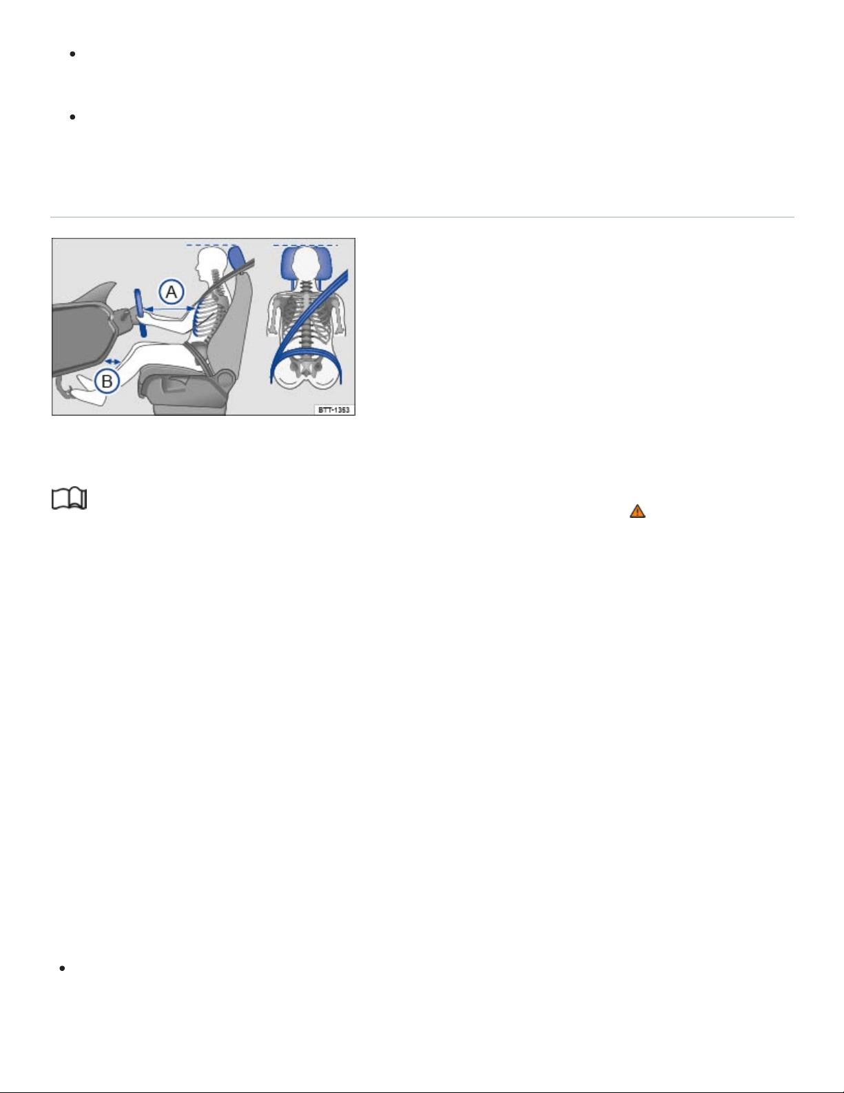
Fig.19Proper safety belt positioning and head restraint adjustment. The driver should never sit
closer than 10inches (25cm) from the steering wheel.
Read and follow the introductory information and safety information first⇒ Introduction to the
subject
The following describes the proper seating positions for the driver and passengers.
If you have a physical impairment or condition that prevents you from sitting properly on the driver
seat with the safety belt properly fastened and reaching the pedals, special modifications to your vehi‐
cle may be necessary. Only the proper seating position ensures optimum protection by the safety belt
and airbag.
Contact your authorized Volkswagen dealer or authorized Volkswagen Service Facility or call the
Volkswagen Customer CARE Center at 1-800-822-8987 for information about possible modifications
to your vehicle.
For your own safety and to reduce injuries in the event of sudden braking maneuvers or accidents,
Volkswagen recommends the following seating positions:
Applies to all vehicle occupants:
Adjust head restraint so that the upper edge of the head restraint is at least at eye level or higher.
Position the back of your head as close as possible to the head restraint ⇒Fig.19 .

Push the head restraint completely down for short people, even if the top of the head is then be‐
low the upper edge of the head restraint.
Tall people should pull the head restraint all the way up.
Adjust the seat backrest angle to an upright position so that your back is in full contact with it
when the vehicle is moving.
Always keep both feet on the floor and in the footwell whenever the vehicle is moving.
Always adjust and fasten safety belts properly ⇒Safety belts .
Driver - seat and steering wheel adjustment:
Adjust the steering wheel so that there are at least 10inches (25cm) between the steering wheel
and your breast bone ⇒Fig.19
Ⓐ
⇒Steering wheel . When adjusting the proper distance to the
steering wheel, grasp the top of the steering wheel with your elbows slightly bent.
Always hold the steering wheel on the outside of the steering wheel rim with your hands at the
9o'clock and 3o'clock positions to help reduce the risk of personal injury if the driver's airbag
inflates.
Never hold the steering wheel at the 12o'clock position or with your hands at other places inside
the steering wheel rim or on the steering wheel hub. Holding the steering wheel the wrong way
can cause serious injuries to the hands, arms, and head if the driver's airbag inflates.
Adjust the steering wheel so that the steering wheel cover points at your chest and not at your
face. Pointing the steering wheel toward your face decreases the ability of the driver's airbag to
help protect you in a collision.
Adjust the driver's seat so that you can easily push the pedals all the way to the floor while keep‐
ing your knee(s) slightly bent. The distance to the instrument panel in the knee area must be at
least 4inches (10cm) ⇒Fig.19
Ⓑ
Adjust the seat height so that the top point of the steering wheel can be reached.
Always keep both feet in the footwell so that you are in control of the vehicle at all times.
Passenger - front seat adjustment:
Push the passenger seat as far back as possible in order to ensure optimum protection if the
airbag is deployed.
Safety belts
Introduction to the subject

In this chapter you will find information on the following subjects:
⇒Warning light
⇒Frontal collisions and laws of physics
⇒What happens to passengers not wearing a safety belt
⇒Safety belts protect
⇒Using safety belts
⇒Fastening and unfastening safety belts
⇒Safety belt position
⇒Safety belt height adjusters
⇒Safety belt retractor, pretensioner, load limiter
⇒Service and disposal of belt pretensioners
Properly worn safety belts are the single most effective means of reducing the risk of serious injury
and death in a collision or other accident.
Damage to safety belts reduces their overall effectiveness and increases the risk of serious personal
injury and death whenever the vehicle is being used.
Check the condition of all safety belts and buckles regularly.
If a safety belt shows damage to webbing, hardware, retractors or buckles, have the safety belt re‐
placed by an authorized Volkswagen dealer or an authorized Volkswagen Service Facility ⇒ .
WARNING
Not wearing a safety belt or wearing an improperly positioned safety belt increases the risk of se‐
vere personal injury or death. Safety belts offer optimum protection only when they are used
properly.

Properly worn safety belts are the single most effective means of reducing the risk of serious
injury and death in a collision or other accident. For this reason, always wear your safety belt
properly and make sure all passengers wear their safety belts properly as well whenever the
vehicle is moving.
The driver must always make sure that every person in the vehicle is properly seated on a
seat of his or her own, properly fastens the safety belts belonging to that seat before the vehi‐
cle starts to move, and keeps the belts properly fastened while riding in the vehicle. This ap‐
plies even when just driving around town. Therefore, always wear your safety belts and make
sure that everybody in your vehicle is properly restrained.
Always secure children in the vehicle with a restraint system appropriate for their age, weight
and height ⇒Child safety and child restraints .
Always fasten safety belts correctly before driving off and make sure that all passengers are
properly restrained.
Never attach the safety belt to the buckle of another seat. Attaching the safety belt to the
wrong buckle will reduce safety belt effectiveness and can cause serious personal injury.
Never let any objects or liquids get into the safety belt latch and prevent it from working
properly.
Never remove a safety belt while the vehicle is moving. Doing so will increase your risk of be‐
ing injured or killed.
Never strap more than one person, including small children, into any single safety belt.
Never let children or babies ride sitting on your lap, and never place a safety belt over a child
sitting on your lap.
Never wear belts over rigid or breakable objects in or on your clothing, such as eyeglasses,
pens, keys, etc., as these may cause injury.
Several layers of heavy clothing (such as a coat worn over a sports jacket) may interfere with
proper positioning of the safety belt and reduce the overall effectiveness of the system.
Never use comfort clips or devices that create slack in the shoulder belt. However, special
clips may be required for the correct use of some child restraint systems.
Safety belts offer optimum protection only when the seat backrest is upright and belts are cor‐
rectly positioned on the body.
WARNING
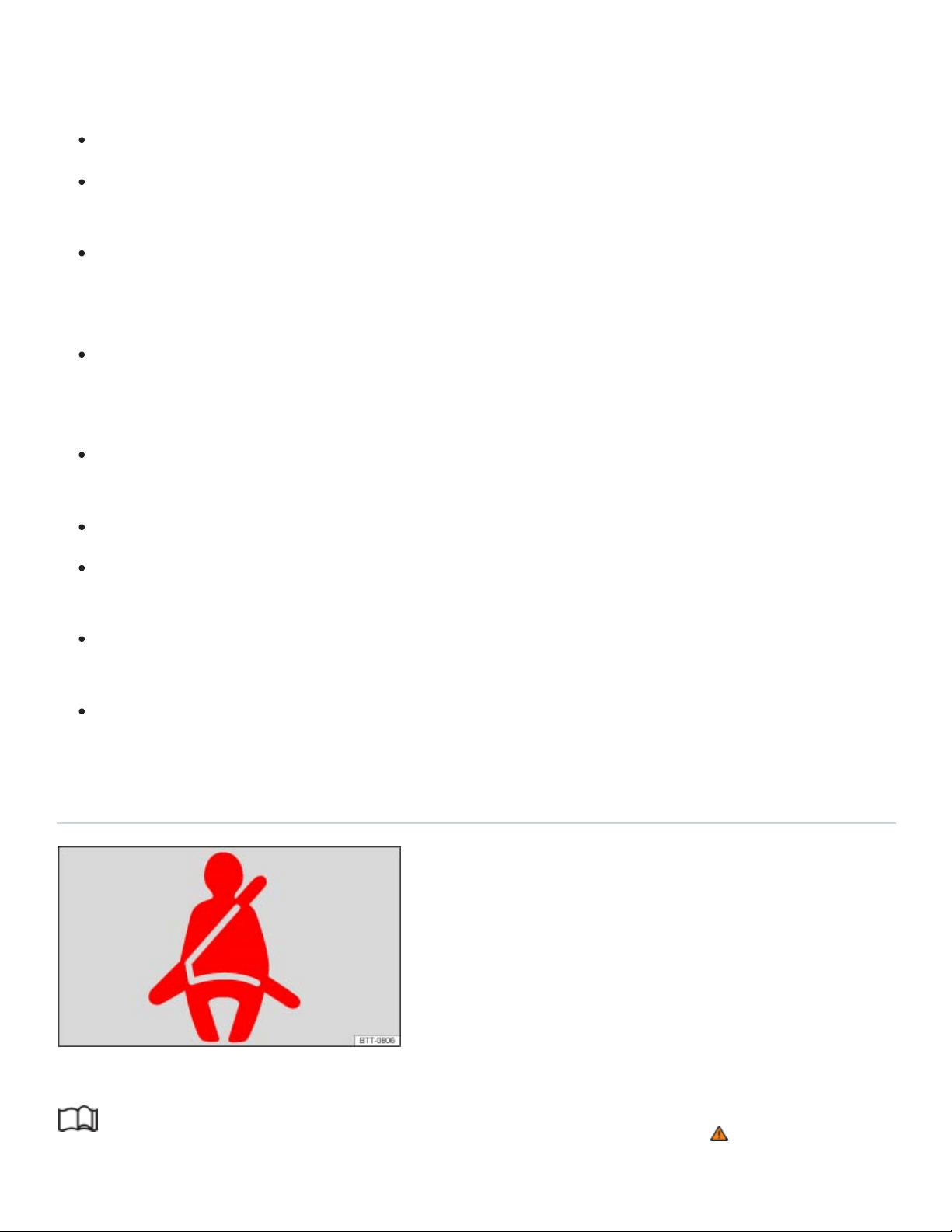
Damage to safety belts reduces their overall effectiveness and increases the risk of serious per‐
sonal injury and death whenever the vehicle is being used.
Never let safety belts become damaged by being caught in the door or seat hardware.
Torn or frayed safety belts can tear, and damaged safety belt hardware can break in an
accident.
Inspect belts regularly for damage. If webbing, hardware, buckles, or retractors are damaged,
have the belts replaced immediately with the correct replacement belts approved by
Volkswagen for your vehicle, model, and model year.
Safety belts that were subject to stress in an accident and stretched must be replaced with a
correct, new safety belt, preferably by an authorized Volkswagen dealer or authorized
Volkswagen Service Facility.
Replacement after a crash may be necessary even if a safety belt shows no visible damage.
Anchorages that have been loaded must also be inspected.
Damaged safety belts must be replaced; they cannot be repaired.
Never try to repair a damaged safety belt yourself. Never remove or modify the safety belts in
any way.
Have safety belts, hardware, retractors and buckles replaced by an authorized Volkswagen
dealer or authorized Volkswagen Service Facility.
Always keep the belts clean. Dirty belts may not work correctly and can impair the function of
the inertia reel.
Warning light
Fig.20Warning light in the instrument cluster.
Read and follow the introductory information and safety information first⇒ Introduction to the
subject

Driver and/or front passenger have not fastened their safety belts, if front passenger seat is
occupied. Fasten safety belts.
When the ignition is switched on, several warning and indicator lights come on briefly for a function
check. They go out after a few seconds.
A warning chime also sounds.
The safety belt warning light comes on for 6seconds when the ignition is switched on. A warning
chime also sounds for up to 6seconds if the driver's safety belt is not buckled. The chime stops
sooner if the driver buckles his or her safety belt. The warning light and the chime go out when both
driver and front passenger have buckled their safety belts.
If the driver and front seat passenger do not both fasten their safety belts within about 24seconds af‐
ter the chime stops and the vehicle is moving at a speed of more than about 15mph (25km/h), the
chime will again sound for about 6seconds, then go off for about 24seconds, then sound again for
about another 6seconds. The same thing happens if one of the safety belts is fastened and then un‐
fastened while the vehicle is moving. The safety belt warning light also flashes. The warning chime
continues to sound at 24second intervals for up to 2minutes. No chime sounds at speeds of less
than about 5mph (8km/h).
If the ignition is switched on, the safety belt warning light stays on until the driver and front passen‐
ger have both buckled their safety belts.
WARNING
Not wearing a safety belt or wearing an improperly positioned safety belt increases the risk of se‐
vere personal injury or death. Safety belts offer optimum protection only when used correctly.
Frontal collisions and laws of physics
Fig.21A vehicle with passengers not wearing safety belts approaches a wall.

Fig.22A vehicle with passengers not wearing safety belts hits a wall.
Read and follow the introductory information and safety information first⇒ Introduction to the
subject
The physical principles of a frontal collision are simple. Both the moving vehicle and the passenger
possess energy ⇒Fig.21 , which varies with vehicle speed and body weight. Engineers call this en‐
ergy kinetic energy.
The higher the speed of the vehicle and the greater the vehicle's weight, the more energy has to be
absorbed in a crash.
Vehicle speed is the most significant factor. If your speed doubles (for example, from 15mph to
30mph – 25km/h to 50km/h), the energy increases 4times!
Because the occupants of the vehicle in the above example are not using safety belts, they are not
attached to the vehicle. In a frontal collision, they will keep moving at the same speed the vehicle was
moving just before the crash, until something stops them - here, the inside of the passenger compart‐
ment. Because the occupants of the vehicle in the example are not wearing safety belts, their entire
kinetic energy will be absorbed by impact with the wall ⇒Fig.22 .
The same principles apply to people in a vehicle that is in a frontal collision on the highway. Even at
city speeds of 20–30mph (30–50km/h), the forces acting on the body can reach one ton (2,000lbs
or 1,000kg) or more. At greater speeds, these forces are even higher.
Of course, the laws of physics don't apply just to frontal collisions; they determine what happens in all
kinds of accidents and collisions.
What happens to passengers not wearing a safety belt
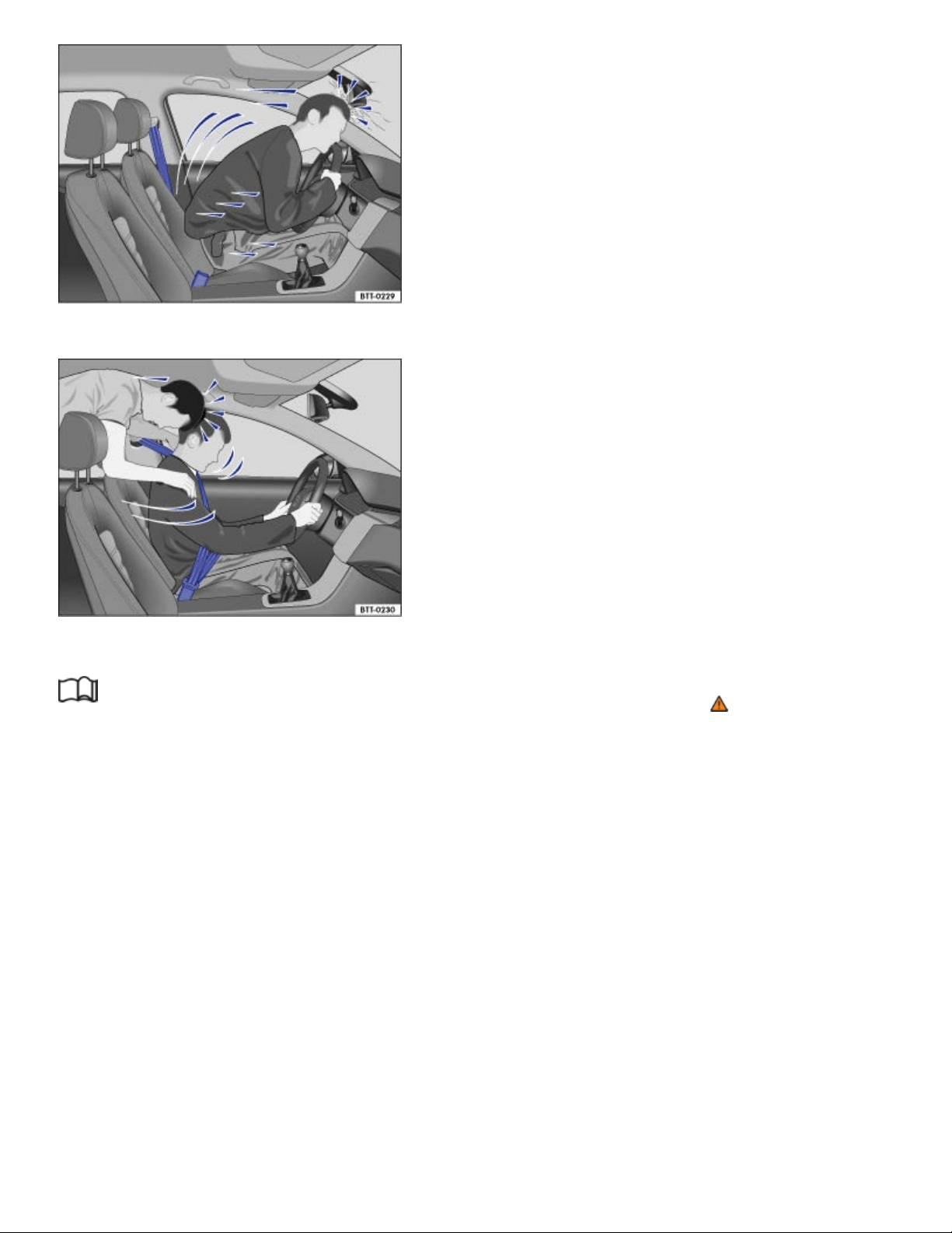
Fig.23The unbelted driver is thrown forward.
Fig.24Unbelted passengers in the rear seats are thrown forward on top of the belted driver.
Read and follow the introductory information and safety information first⇒ Introduction to the
subject
Many people believe that it is possible to resist the forces of an impact by holding tight or bracing
themselves. That is simply not true!
Even at low collision speeds, the forces acting on the body are too much for the body to be held in the
seat with the arms and hands. In a frontal collision, unrestrained occupants will slam violently into the
steering wheel, instrument panel, windshield or anything else in the way ⇒Fig.23 .
Never rely on airbags alone for protection. Even when they deploy, airbags provide only additional
protection. Airbags are not supposed to deploy in all kinds of accidents. Even if your vehicle is
equipped with airbags, all vehicle occupants, including the driver, must wear safety belts correctly in
order to minimize the risk of severe injury or death in a crash, regardless of whether a seating posi‐
tion has an airbag or not.

An airbag will deploy only once. Safety belts are always there to offer protection in those accidents in
which airbags are not supposed to deploy or when they have already deployed. Unbelted occupants
can also be thrown out of the vehicle, causing even more severe injuries or death.
It is also important for occupants in the rear seats to wear their safety belts properly since they can be
thrown violently forward through the vehicle in the event of an accident. Unbelted passengers in the
rear seats endanger not only themselves but also the driver and other passengers in the vehicle
⇒Fig.24 .
Safety belts protect
Fig.25Belted driver secured by the correctly worn safety belt in the event of a sudden braking
maneuver.
Read and follow the introductory information and safety information first⇒ Introduction to the
subject
Used properly, safety belts can make a big difference. Safety belts help to keep passengers in their
seats, gradually reduce energy levels applied to the body in a collision, and help prevent the uncon‐
trolled movement that can cause serious injuries. In addition, safety belts reduce the danger of being
thrown out of the vehicle ⇒Fig.25 .
Safety belts attach passengers to the car and give them the benefit of being slowed down more gen‐
tly or softly through the give in the safety belts, crumple zones, and other safety features (such as
airbags) engineered into today's vehicles. The front crumple zones and other passive safety features
(such as the airbag system) are also designed to absorb kinetic energy. By absorbing the kinetic en‐
ergy over a longer period of time, the forces on the body become more tolerable and less likely to
cause injury.

Although these examples are based on a frontal collision, safety belts can also substantially reduce
the risk of injury in other kinds of crashes. So, whether you're on a long trip or just going to the corner
store, always buckle up and make sure that others do, too.
Accident statistics show that vehicle occupants properly wearing safety belts have a lower risk of be‐
ing injured and a much better chance of surviving a collision. Properly using safety belts also greatly
increases the ability of the supplemental airbags to do their job in a collision. For this reason, wearing
a safety belt is required by law in most countries including the United States and Canada.
Although your Volkswagen is equipped with airbags, you still have to wear the safety belts provided.
Front airbags, for example, are activated only in some frontal collisions. The front airbags are not acti‐
vated in all frontal collisions, in side and rear collisions, in rollovers, or in cases when the conditions
for deployment stored in the electronic control unit are not met. The same goes for the other airbag
systems on your Volkswagen.
So always wear your safety belt and make sure that everybody in your vehicle is properly restrained!
Using safety belts
Read and follow the introductory information and safety information first⇒ Introduction to the
subject
Checklist
Using safety belts ⇒
Damage to safety belts reduces their overall effectiveness and increases the risk of serious
personal injury and death whenever the vehicle is being used.
Check the condition of all safety belts and buckles regularly.
Keep safety belts clean.
Keep objects and liquids away from safety belt webbing, the safety belt buckle tongue, and the
safety belt buckle latch and opening.
Do not pinch or damage the safety belt or buckle tongue (for instance, when closing a door).
Never modify, disassemble or try to repair safety belts and safety belt anchorages.
Always fasten your safety belt properly before driving and keep it fastened whenever the vehi‐
cle is moving.

Twisted safety belt
If it is difficult to pull the safety belt out of the belt guide, the belt may be twisted inside the side trim
because the belt retracted too quickly when it was taken off.
Hold the safety belt tongue, slowly and carefully pull safety belt all the way out.
Untwist the safety belt and slowly return the belt by hand.
If you cannot untwist the safety belt, wear it anyway. Make sure that the safety belt is twisted in a spot
where it does not come in direct contact with your body. Have the safety belt untwisted immediately
by an authorized Volkswagen dealer or authorized Volkswagen Service Facility.
Lockable safety belt
The retractors for the rear seat safety belts and the front passenger safety belt have a switchable
locking feature for child restraints in addition to the emergency locking feature. Whenever a child re‐
straint is installed with a safety belt, the safety belt must be locked so that the safety belt webbing
cannot unreel. The switchable locking feature lets you lock the belt so that a child restraint can be
properly installed and, for example, so that it can't tip to the side when the vehicle goes around a cor‐
ner ⇒Child safety and child restraints .
To see whether a safety belt is lockable, pull the safety belt all the way out of the safety belt retractor.
You should then hear a clicking sound as the belt winds back into the retractor reel. Test the switch‐
able locking feature by pulling on the belt. When the switchable locking feature is active, you should
no longer be able to pull the belt out of the retractor.
The locking feature must be deactivated when a vehicle occupant uses the safety belt.
WARNING
Improper use and care of safety belts increases the risk of severe personal injury or death.
Regularly check safety belts and related parts for damage.
Damaged safety belts must be replaced; they cannot be repaired.
Always keep safety belts clean.
Never catch, damage or chafe safety belt webbing on sharp edges.
Always keep objects and liquids away from the belt buckle and buckle opening.
Fastening and unfastening safety belts
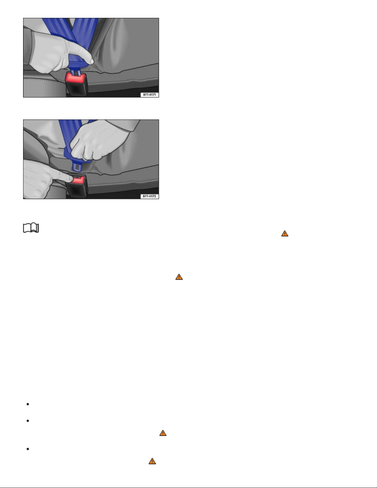
Fig.26Inserting the buckle tongue into the belt buckle.
Fig.27Releasing the buckle tongue from the belt buckle.
Read and follow the introductory information and safety information first⇒ Introduction to the
subject
Properly worn safety belts help to hold occupants in their seats and provide optimum protection dur‐
ing braking or in a collision or other accident ⇒ .
The switchable locking feature makes a clicking sound when the safety belt is winding back onto the
safety belt retractor wheel after being pulled all the way out. Whenever a child restraint is installed
with a safety belt, the safety belt must be locked so that the safety belt webbing cannot unreel
⇒Child safety and child restraints . If active, deactivate the locking feature before using the safety
belt to restrain a person without a child restraint system.
Fastening safety belts
Always buckle your safety belt before driving.
Adjust the front seat and head restraint correctly ⇒Seats and head restraints .
Make sure the seat backrest of the rear seat bench is in an upright position and securely latched
in place before using the safety belt ⇒ .
Hold the safety belt by the tongue and pull it slowly and evenly across the chest and pelvis. Do
not twist the safety belt webbing ⇒ .
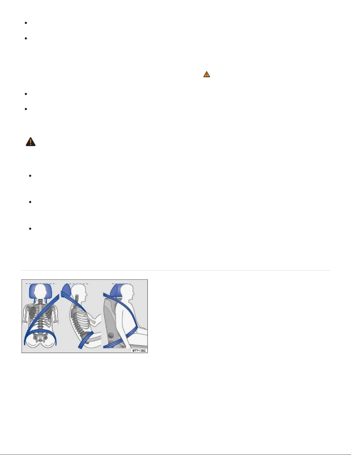
Insert the tongue into the correct buckle for your seat until you hear it latch securely ⇒Fig.26 .
Pull on the safety belt to make sure that it is securely latched in the buckle.
Unfastening safety belts
Unfasten safety belts only when the vehicle is not moving ⇒ .
Press the red button on the buckle ⇒Fig.27 . The buckle tongue is ejected.
Let the belt wind up on the retractor as you guide the belt tongue to its stowed position to help
prevent the safety belt from twisting and to help avoid damage to the interior trim.
WARNING
Improperly positioned safety belts can cause serious personal injury or death in an accident.
Safety belts offer optimum protection only when the seat backrest is upright and belts are cor‐
rectly positioned on the body.
A person who is not properly restrained can be seriously injured by the safety belt itself if it
slips from the stronger parts of the body into sensitive areas like the abdomen.
Unfastening safety belts while the vehicle is in motion can cause severe personal injury or
death in the event of an accident or braking maneuver!
Safety belt position
Fig.28Proper safety belt positioning and head restraint adjustment.

Fig.29Proper safety belt positioning for expectant mothers.
Read and follow the introductory information and safety information first⇒ Introduction to the
subject
Wearing safety belts improperly can cause serious injury or death. Safety belts can only work when
they are correctly positioned on the body. A properly worn safety belt also helps to position the occu‐
pant so that an airbag can provide maximum protection when deployed. Therefore, always fasten
your safety belt and make sure that it is properly positioned over your body.
Improper seating positions reduce the effectiveness of safety belts and even increase the risk of in‐
jury or death by moving the safety belt to critical areas of the body. Improper seating positions also
increase the risk of severe injury or death when an airbag deploys and strikes an occupant who is not
seated properly ⇒Sitting properly and safely .
Proper safety belt position
The shoulder portion of the safety belt must always run over the center of the shoulder and never
over the throat, over the arm, under the arm or behind the back.
The lap portion of the safety belt must always run as low as possible over the pelvis and never
over the abdomen.
Always wear the safety belt flat and snug against the body. Pull on the safety belt to tighten if
necessary.
Expectant mothers must always wear the lap portion of the safety belt as low as possible across the
pelvis and below the rounding of the abdomen – throughout the pregnancy. The safety belt must lie
flat against the body to avoid pressure against the abdomen ⇒Fig.29 .
Adjusting safety belt height
The safety belt position can be adjusted using the following features:

Safety belt height adjusters for the front seats.
Front seats with height adjustment.
WARNING
Improperly positioned safety belts can cause serious personal injury in an accident or a sudden
braking maneuver.
Always make sure that all vehicle occupants are correctly restrained and stay in a correct seat‐
ing position whenever the vehicle is being used.
Safety belts offer optimum protection only when the seat backrest is upright and belts are cor‐
rectly positioned on the body.
A loose-fitting safety belt can cause serious injuries by shifting its position on your body from
the strong bones to more vulnerable soft tissue and cause serious injury.
The shoulder belt portion of the safety belt must be positioned over the middle of the
occupant's shoulder and never across the neck or throat.
The safety belt must lie flat and snug on the occupant's upper body.
Never wear the shoulder part of the safety belt under your arm or otherwise out of position.
The lap portion of the safety belt must be positioned as low as possible across the pelvis and
never over the abdomen. Make sure the belt lies flat and snug against the pelvis. Pull on the
safety belt to tighten if necessary.
Expectant mothers must always wear the lap portion of the safety belt as low as possible
across the pelvis and below the rounding of the abdomen.
Do not twist the belt when attaching it. If you cannot untwist a twisted safety belt, wear it any‐
way, but make sure the twisted part is not in contact with your body. Have the problem cor‐
rected right away by an authorized Volkswagen dealer or authorized Volkswagen Service
Facility.
Never hold the safety belt away from your body with your hand.
Never wear belts over rigid or breakable objects, such as eyeglasses, pens or keys.
Never modify the position of the belt using comfort clips, loops or similar devices.
If you have a physical impairment or condition that prevents you from sitting properly on the seat
with the safety belt properly fastened, special modifications to your vehicle may be necessary.
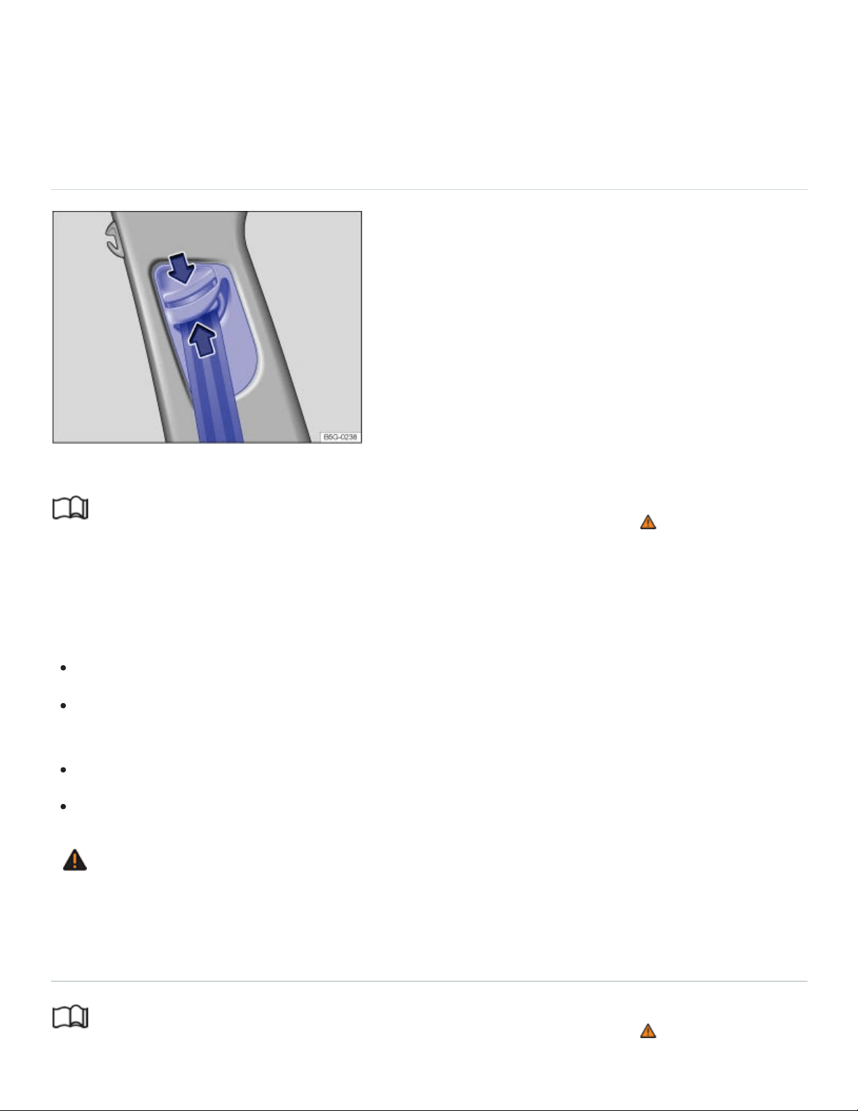
Contact your authorized Volkswagen dealer or authorized Volkswagen Service Facility or call the
Volkswagen Customer CARE Center at 1-800-822-8987 for information about possible modifica‐
tions to your vehicle.
Safety belt height adjusters
Fig.30Next to the front seats: Safety belt height adjuster.
Read and follow the introductory information and safety information first⇒ Introduction to the
subject
Safety belt height adjusters for the front seats can be used to adjust the height of the shoulder portion
of the safety belt so that it is positioned correctly:
Pinch the safety belt attachment together as indicated by the arrows and hold ⇒Fig.30 .
Slide the belt and upper attachment up or down until the safety belt is positioned over the center
of the shoulder ⇒Safety belts .
Release the safety belt attachment.
Pull on the safety belt to make sure that the upper attachment is securely locked in place.
WARNING
Never adjust the height of the safety belt while driving.
Safety belt retractor, pretensioner, load limiter
Read and follow the introductory information and safety information first⇒ Introduction to the
subject

The safety belts in the vehicle are part of the vehicle's safety concept ⇒Airbags and how they work
and consist of the following important features:
Automatic safety belt retractors
Every safety belt is equipped with an automatic safety belt retractor on the shoulder belt. As long as
the safety belt is pulled out slowly, the shoulder belt will extend to let you move freely under normal
driving conditions. The automatic safety belt retractor locks the belt when the belt is pulled out fast
during hard braking and in a collision. The belt may also lock when you drive up or down a steep hill
or through a sharp curve.
Safety belt pretensioner
The safety belt retractors for the driver and front seat passenger have a pretensioner that helps take
the slack out of the safety belt and tighten it when the pretensioner is activated.
The pretensioners are activated by the electronic control unit for the airbag system in front, side, and
rear collisions, and in rollovers. By tightening the safety belt, the pretensioner helps to reduce the
occupant's forward movement. The belt pretensioner works together with the airbag system; its func‐
tion is monitored by the airbag system indicator light.
A fine dust may be released upon activation. This is normal and is not caused by a fire in the vehicle.
Safety belt load limiter
The safety belts also have load limiters to help reduce the forces applied to the body in a crash.
Heed all safety regulations if the vehicle or individual components of the system have to be
scrapped. Your authorized Volkswagen dealer and authorized Volkswagen Service Facility are
familiar with these regulations ⇒Service and disposal of belt pretensioners .
Service and disposal of belt pretensioners
Read and follow the introductory information and safety information first⇒ Introduction to the
subject
The pretensioners are part of the safety belts installed at the front seats in your vehicle. Installing, re‐
moving, servicing, or repairing of safety belt pretensioners can damage the safety belt system and
prevent it from working correctly in a collision. The pretensioners themselves may then also not work

in the event of an accident, or not work properly.
There are some important things you have to know to make sure that the effectiveness of the system
will not be impaired and that discarded components do not cause injury or pollute the environment.
Undeployed safety belt pretensioners and airbag modules contain explosive materials that can cause
serious injuries to the general public and to people who work at dealerships and workshops, scrap
yards, and recycling facilities. For this reason, the systems must be properly handled when they or
the vehicles they are installed in are scrapped.
Undeployed safety belt pretensioners and airbag modules can also pollute the environment. Never
abandon vehicles or vehicle parts. If your vehicle must be scrapped, please make sure that it is done
safely, responsibly, and in compliance with all applicable environmental regulations. Take it to a li‐
censed facility that has the knowledge and experience to properly dispose of the vehicle and its
safety belt system. Your authorized Volkswagen dealer and authorized Volkswagen Service Facility
are familiar with these regulations.
WARNING
Improper handling, care, servicing, and repair procedures can increase the risk of personal injury
and death by preventing a belt pretensioner from activating when needed or by causing it to acti‐
vate unexpectedly.
The pretensioner can be activated only once. If a pretensioner has been activated, the safety
belt must be replaced.
Safety belt systems including the pretensioners cannot be repaired. Special procedures are
required to remove, install, and dispose of this system.
Never repair, adjust, or change pretensioners or any other part of the safety belt system your‐
self. We strongly recommend that you have any work on the safety belt system performed by
an authorized Volkswagen dealer or authorized Volkswagen Service Facility. They have the
necessary technical information, training, and special equipment ⇒Parts and accessories .
WARNING
Undeployed safety belt pretensioners and airbag modules contain explosive materials that can
cause serious personal injuries if they are not properly handled when they or the vehicles they
are installed in are scrapped.
Never abandon vehicles or vehicle parts.

Always scrap vehicles and vehicle parts, especially those containing undeployed airbag mod‐
ules and undeployed safety belt pretensioners, at a licensed facility that has the knowledge
and experience to properly dispose of the vehicle and its safety belt and airbag systems.
Undeployed airbag modules and safety belt pretensioners are classified as Perchlorate
Material. Special handling may apply – see http://www.dtsc.ca.gov/hazardouswaste/perchlorate.
Obey all applicable legal requirements regarding handling and disposal of the vehicle or parts of
its restraint system, including airbag modules and safety belts with pretensioners. Authorized
Volkswagen dealers and authorized Volkswagen Service Facilities are familiar with the require‐
ments, and we recommend that you have them perform this service for you.
Airbag system
Introduction to the subject
In this chapter you will find information on the following subjects:
⇒Advanced Airbag System, infants, child restraints, and children on the front seat
⇒Monitoring the Advanced Airbag System
⇒PASSENGERAIRBAG light
⇒Airbags and how they work
⇒The dangers of using child restraints on the front seat
⇒Front airbags
⇒Advanced Airbag System components
⇒How to tell if the front passenger front airbag is on or off
⇒Side airbags
⇒Side Curtain Protection® airbags

Your vehicle is equipped with a front airbag for the driver and front seat passenger. The front airbags
can provide additional protection for the chest and head of the driver and the front seat passenger
when seats, safety belts, head restraints and, for the driver, the steering wheel, are properly used and
have been properly adjusted. Airbags are only supplemental restraints. They are not a substitute for
safety belts that must be worn even though the front seating positions are equipped with front
airbags.
WARNING
Never rely on airbags alone for protection.
Even when they deploy, airbags provide only supplemental protection.
Airbags work most effectively when used with properly worn safety belts ⇒Safety belts .
The driver must always make sure that every person in the vehicle is properly seated on a
seat of his or her own, properly fastens the safety belts belonging to that seat before the vehi‐
cle starts to move, and keeps the belts properly fastened while riding in the vehicle. This ap‐
plies even when just driving around town. Therefore, always wear your safety belts and make
sure that everybody in your vehicle is properly restrained.
WARNING
Sitting too close to the steering wheel or instrument panel will decrease the effectiveness of the
airbags and will increase the risk of personal injury in a collision.
Never sit closer than 10inches (25cm) to the steering wheel or instrument panel.
If you cannot sit upright more than 10inches (25cm) from the steering wheel and with your
back against the backrest, investigate whether adaptive equipment may be available to help
you reach the pedals and increase your seating distance from the steering wheel.
If you are unrestrained, leaning forward, sitting sideways or out of position in any way, your
risk of injury is much higher.
You will also receive serious injuries and could even be killed if you are up against the airbag
or too close to it when it inflates.
To reduce the risk of injury when an airbag inflates, always wear safety belts properly. See
⇒Safety belts .
An infant in a rearward-facing child restraint installed on the front passenger seat will be seri‐
ously injured and can be killed if the front airbag inflates.

Always make certain that children age12 or younger always ride in the rear seat. If children
are not properly restrained, they may be severely injured or killed when an airbag inflates.
Never let children ride unrestrained or improperly restrained in the vehicle.
Never put your feet on the instrument panel or on the seat. Always keep both feet on the floor
in front of the seat to help prevent serious injuries to the head, legs and hips if the airbag
inflates.
WARNING
Objects between you and the airbag will increase the risk of injury in a crash by interfering with
the way the airbag unfolds or by being pushed into you as the airbag inflates.
Never hold things in your hands or on your lap when the vehicle is moving.
Never transport items on or in the area of the front passenger seat. Objects could move into
the area of the front airbags during braking or other sudden maneuvers and fly dangerously
through the passenger compartment when an airbag inflates.
Always make sure that the airbag deployment zones are clear at all times. Never let any thing
or object, a pet, or a person, including an infant or small child, be in the space between any
vehicle occupant and any airbag at any time.
WARNING
An airbag works only once. Airbags that have deployed in a crash must be replaced.
Deployed airbags and the related system parts must be replaced immediately with new parts
approved by Volkswagen for the vehicle model and model year.
Have repairs and vehicle modifications performed by an authorized Volkswagen dealer or au‐
thorized Volkswagen Service Facility. Authorized Volkswagen dealers and authorized
Volkswagen Service Facilities have the required tools, diagnostic equipment, repair informa‐
tion, and trained personnel to properly replace any airbag in your vehicle and assure system
effectiveness in a crash.
Never permit salvaged or recycled airbags to be installed in your vehicle.
Never modify any components of the airbag system.
WARNING

Fine dust released when airbags deploy can irritate the skin, eyes, and mucous membranes as
well as cause breathing problems for people who suffer from asthma or other respiratory
conditions.
To reduce the risk of breathing problems, those with asthma or other respiratory conditions
should get fresh air right away by getting out of the vehicle or opening windows or doors.
If you are in a collision in which airbags deploy, wash your hands and face with mild soap and
water before eating.
Be careful not to get the dust into your eyes or into any cuts, scratches, or open wounds.
If the residue should get into your eyes, flush them with water.
WARNING
Using solvents or other improper cleaning products on surfaces where airbags are located can
change the way airbags deploy in a crash.
Products containing solvents will change the properties of the plastics and may cause plastic
parts to break and fly around when the airbag deploys in a crash, causing injury.
Never use solvents or cleaners on the steering wheel horn pad or on the instrument panel be‐
cause they can damage the airbag cover or change the stiffness or strength of the material so
that the airbag cannot deploy and protect properly.
When cleaning the horn pad and instrument panel, use only a soft, dry cloth or a cloth moist‐
ened with plain water.
Advanced Airbag System, infants, child restraints, and children on the front
seat
Read and follow the introductory information and safety information first⇒ Introduction to the
subject
Be sure to read the important information and the WARNINGS for important details about children
and Advanced Airbags ⇒Child safety and child restraints .
The Advanced Airbag System in your vehicle has been certified to comply with the requirements of
the United States Federal Motor Vehicle Safety Standard (FMVSS)208, as well as Canada Motor
Vehicle Safety Standard (CMVSS)208 as applicable at the time your vehicle was manufactured.

According to requirements, the front Advanced Airbag System on the passenger side has been certi‐
fied for suppression for infants of about 12months old and younger and for low risk deployment for
children aged 3to 6years old (as defined in the standard).
Even though your vehicle is equipped with an Advanced Airbag System, make certain that all chil‐
dren, especially 12years and younger, always ride on the back seat properly restrained for their age
and size. The airbag on the front passenger side makes the front seat a potentially dangerous place
for a child to ride. The front seat is not the safest place for a child in a forward-facing child restraint. It
is a very dangerous place for an infant or a child in a rearward-facing seat.
DANGER!
The front seat of any vehicle can be a dangerous place for a child - even with an Advanced
Airbag System.
If the front airbag inflates, a child or infant who
is unrestrained on the front seat,
is in an improperly installed forward-facing child restraint on the front seat, or
is in any rearward-facing child restraint on the front seat will be seriously injured and can
be killed.
Even though your vehicle is equipped with an Advanced Airbag System, make certain that all
children, especially 12years and younger, always ride on the back seat properly restrained for
their age and size.
Always properly install rearward-facing child restraints or infant carriers and forward-facing
child restraints on the rear seat - even with an Advanced Airbag System.
Monitoring the Advanced Airbag System
Read and follow the introductory information and safety information first⇒ Introduction to the
subject
The Advanced Airbag System as well as the side airbags, Side Curtain Protection airbags with ejec‐
tion mitigation features (including the electronic control unit, sensors and system wiring) are all moni‐
tored continuously to make sure that they are functioning properly whenever the ignition is on. Every
time you turn on the ignition, the airbag system indicator light will come on for a few seconds
(function check).
®
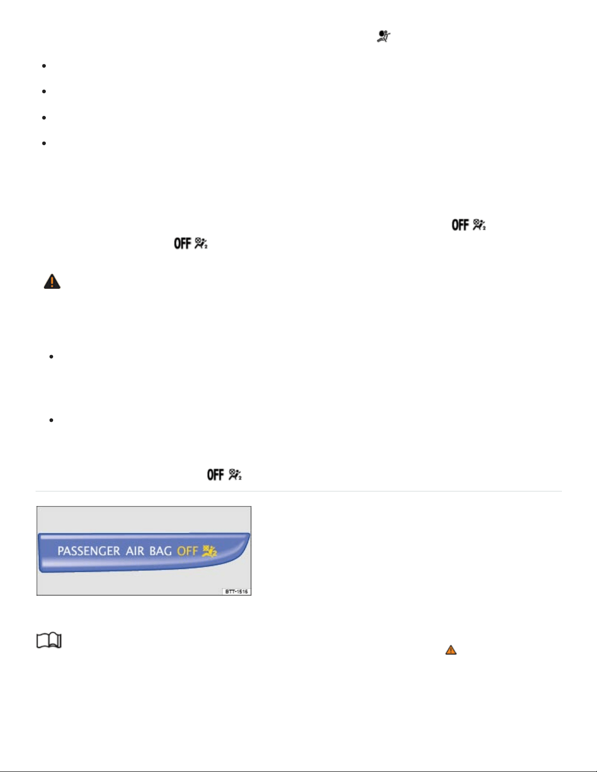
The airbag system must be inspected if the airbag indicator light
does not light up when the ignition is switched on,
does not go out a few seconds after you have switched on the ignition,
goes out and then lights up again or blinks after the ignition is switched on,
or if it lights up or blinks while driving.
If an airbag system malfunction is detected, the airbag indicator light comes on and stays on to alert
the driver to the problem. It also reminds you to have the airbag system checked immediately by an
authorized Volkswagen dealer or an authorized Volkswagen Service Facility. If a malfunction occurs
that turns the front airbag on the passenger side off, the PASSENGERAIRBAG light
⇒PASSENGERAIRBAG light will come on and stay on whenever the ignition is on.
WARNING
An airbag system and safety belt pretensioner that are not working properly cannot provide sup‐
plemental protection in a frontal crash.
If the airbag indicator light comes on, it means that there may be something wrong with the
Advanced Airbag System. It is possible that the airbag will inflate when it is not supposed to, or
will not inflate when it should.
Have the airbag system inspected immediately by your authorized Volkswagen dealer or au‐
thorized Volkswagen Service Facility.
PASSENGERAIRBAG light
Fig.31In the instrument panel: PASSENGERAIRBAG light.
Read and follow the introductory information and safety information first⇒ Introduction to the
subject
On Location Possible cause Solution

On Location Possible cause Solution
Instrument cluster
Airbag and safety belt preten‐
sioner system malfunction.
See your authorized Volkswagen
dealer or authorized Volkswagen
Service Facility immediately to have
the system checked.
Instrument panel
⇒Fig.31
Airbag system malfunction.
See your authorized Volkswagen
dealer or authorized Volkswagen
Service Facility immediately to have
the system checked.
Front passenger airbag turned
off by Advanced Airbag
System.
Check if the airbag must stay turned
off.
The PASSENGERAIRBAG light ⇒Fig.31 will come on and stay on to tell you when the front
Advanced Airbag System on the passenger side has been turned off by the electronic control unit.
If the PASSENGERAIRBAG light burns out, the airbag indicator light ⇒Monitoring the
Advanced Airbag System will come on and signal a malfunction in the Advanced Airbag System.
Although the burned-out light will not change the way the front airbag on the passenger side works, it
will no longer be possible to use the PASSENGERAIRBAG light to make sure that the airbag
on/off status is correct for the occupant on the front passenger seat. Have the airbag system in‐
spected immediately by your authorized Volkswagen dealer or authorized Volkswagen Service
Facility.
The PASSENGERAIRBAG light will blink for about 5seconds when:

the ignition is switched on and
the capacitive passenger detection system, which switches the front seat passenger's front
Advanced Airbag on and off, detects a change in the status of the front passenger seat.
After the PASSENGERAIRBAG light stops blinking, always make sure that the airbag status
(on or off) as shown by the PASSENGERAIRBAG light is proper for the size, age, and weight
(electrical capacitance) of the occupant on the front passenger seat. Always make sure that the safety
belt for the front passenger seat is properly fastened.
The PASSENGERAIRBAG light will show the status of the front seat passenger's front
Advanced Airbag System a few seconds after the ignition has been switched on and the airbag moni‐
toring light goes off. The PASSENGERAIRBAG light:
will stay on if the front passenger seat is not occupied;
will stay on if the electrical capacitance measured by the capacitive passenger detection system
for the front passenger seat equals the combined capacitance of an infant up to about 1year of
age and one of the rearward-facing or forward-facing child restraints listed in Federal Motor
Vehicle Safety Standard208 with which the Advanced Airbag System in your vehicle was certi‐
fied. For a listing of the child restraints that were used to certify your vehicle's compliance with the
U.S. Safety Standard ⇒Child safety and child restraints ;
will go out if the front passenger seat is occupied by an adult as registered by the capacitive pas‐
senger detection system.
The PASSENGERAIRBAG light must come on and stay on if the ignition is on and…
a car bed has been installed on the front passenger seat, or
a rearward-facing child restraint has been installed on the front passenger seat, or
a forward-facing child restraint has been installed on the front passenger seat,
and if the electrical capacitance registered on the front passenger seat is equal to or less than the
combined capacitance of a typical 1year-old infant and one of the rearward-facing or forward-fac‐
ing child restraints listed in Federal Motor Vehicle Safety Standard208 with which the Advanced
Airbag System in your vehicle was certified.
If the front passenger seat is not occupied, the front passenger airbag will not deploy, and the
PASSENGERAIRBAG light will stay on.

Never install a rearward-facing child restraint on the front passenger seat. The safest place for a child
in any kind of child restraint is on the rear seat ⇒The dangers of using child restraints on the front
seat , and ⇒Child safety and child restraints .
If the PASSENGERAIRBAG light comes on…
If the PASSENGERAIRBAG light comes on when one of the conditions listed above is met,
be sure to check the light regularly to make certain that the PASSENGERAIRBAG light stays
on continuously whenever the ignition is on. If the PASSENGERAIRBAG light does not come
on and stay on all the time, stop as soon as it is safe to do so AND
reactivate the airbag system by turning the ignition off for more than 4seconds and then turning it
on again;
remove and reinstall the child restraint. Make sure that the child restraint is properly installed and
that the safety belt for the front passenger seat has been correctly routed around or through the
child restraint as described in the child restraint manufacturer's instructions;
make sure that the switchable locking feature on the safety belt for the front passenger seat has
been activated and that the safety belt has been pulled tight;
make sure that no electrical device (such as a laptop, CD player, or electronic games device) is
placed or used on the front passenger seat.
make sure that no seat heater has been retrofitted or otherwise added to the front passenger seat;
make sure that nothing can interfere with the safety belt buckles and that they are not obstructed;
make sure that there are no wet objects (such as a wet towel) and no water or other liquids on the
front passenger seat cushion.
If the PASSENGERAIRBAG light still does not come on…
If the PASSENGERAIRBAG light still does not come on and does not stay on continuously
(when the ignition is switched on), take the child restraint off the front passenger seat and install it
properly at one of the rear seat positions. Have the airbag system inspected immediately by your au‐
thorized Volkswagen dealer or authorized Volkswagen Service Facility.
The PASSENGERAIRBAG light should NOT come on…
The PASSENGERAIRBAG light should NOT come on when the ignition is on and an adult is
sitting in a proper seating position on the front passenger seat. If the PASSENGERAIRBAG
light comes on and stays on under these circumstances, make sure that:
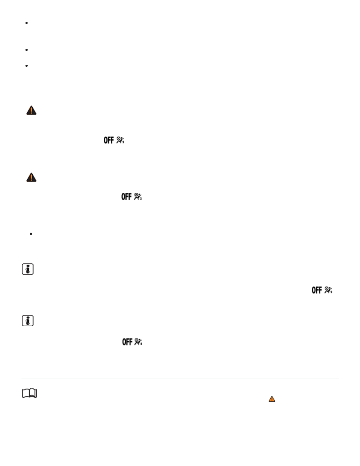
the adult on the front passenger seat is properly seated on the center of the seat cushion with his
or her back up against the backrest and the backrest is not reclined;
the safety belt is being properly worn and that there is not a lot of slack in the safety belt webbing;
there are no aftermarket seat covers or cushions or other things (such as blankets) on the front
passenger seat that might cause the capacitive passenger detection system to miscalculate elec‐
trical capacitance.
WARNING
If the status of the Advanced Airbag System has changed while the vehicle is moving, the
PASSENGERAIRBAG light blinks for about 5seconds to catch the driver's attention. If
this happens, always stop as soon as it is safe to do so and check the steps described above.
WARNING
If the PASSENGERAIRBAG light does not go off when an adult who is not very small is
sitting on the front passenger seat after taking the steps described above, make sure the adult is
properly seated and restrained at one of the rear seating positions.
Have the airbag system inspected by your authorized Volkswagen dealer or authorized
Volkswagen Service Facility before transporting anyone on the front passenger seat.
If the capacitive passenger detection system determines that the front passenger seat is empty,
the front airbag on the passenger side will be turned off, and the PASSENGERAIRBAG
light will stay on.
If the front passenger safety belt itself is buckled and the front passenger seat is not occupied,
the PASSENGERAIRBAG light will come on and stay on.
Airbags and how they work
Read and follow the introductory information and safety information first⇒ Introduction to the
subject
Front airbags and how they work

Airbags are only supplemental restraints. They are not a substitute for safety belts that must be worn
even though the front seating positions are equipped with front airbags. The front airbags can provide
additional protection for the chest and head of the driver and the front seat passenger when seats,
safety belts, head restraints and, for the driver, the steering wheel, are properly used and have been
properly adjusted.
When the airbag system deploys in a collision, a gas generator fills the airbags that break open the
padded covers on the steering wheel and the instrument panel. The front airbags inflate between the
steering wheel and the driver and between the instrument panel and the front passenger.
Front airbags in combination with properly worn safety belts slow down and limit the occupant's for‐
ward movement. Together they help to prevent the driver and front seat passenger from hitting parts
of the vehicle interior, thereby reducing the forces acting on the occupants during a crash. In this way,
they help to reduce the risk of injury to the head and upper body during a crash. Airbags do not pro‐
vide protection for the arms and lower body parts. It is important to remember that the supplemental
airbag system is designed to reduce the likelihood of serious injuries. However, it is possible that a
deployed airbag may cause other injuries such as swelling, bruising, friction burns, and abrasions.
Airbags inflate in the blink of an eye, so fast that many people don't even realize that the airbags have
deployed. The airbags will deflate immediately after deployment so that the front occupants can see
through the windshield again without interruption.
Airbags inflate with a great deal of force. Airbags can cause serious injuries when they inflate and hit
those who are sitting too close, are out of position, or are not properly restrained. By keeping room
between your body and the steering wheel and the front of the passenger compartment, the airbag
can inflate fully and completely and provide supplemental protection during certain frontal collisions
⇒Safety belts .
Make sure that nothing is in the way of the airbags when they deploy. For example, things on your lap
or on the seat could be pushed into your body or fly dangerously through the passenger compartment
when the airbag inflates and cause serious personal injury.
The areas outlined in red (dotted lines) ⇒Fig.32 and ⇒Fig.33 indicate the airbag deployment zone.
Never place or attach accessories or other objects (such as cup holders, telephone brackets, note
pads, or heavy or bulky objects) on the doors, on the windshield, over or near the area marked in red
(dotted lines).
Physical impairments and airbags

If you have a physical impairment or condition that prevents you from sitting properly on the driver
seat with the safety belt properly fastened and reaching the pedals, special modifications to your vehi‐
cle may be necessary. The safety belt and airbag can only provide optimum protection if you are
seated correctly and can reach the pedals.
Contact your authorized Volkswagen dealer or authorized Volkswagen Service Facility or call the
Volkswagen Customer CARE Center at 1-800-822-8987 for information about possible modifications
to your vehicle.
When airbags deploy
Deployment of the front airbags and the activation of the safety belt pretensioners depend on the de‐
celeration measured by the crash sensors and registered by the electronic control unit. Crash severity
depends on speed and deceleration as well as the mass and stiffness of the vehicle or object in‐
volved in the crash.
The front airbags will not inflate in side or rear collisions, in rollovers or if the ignition is switched off.
The front airbags will not inflate in all frontal collisions. The triggering of the airbag system depends
on the vehicle deceleration rate caused by the collision and registered by the electronic control unit. If
this rate is below the reference value programmed into the control unit, the airbags will not be trig‐
gered, even though the vehicle may be badly damaged as a result of the collision. Vehicle damage,
repair costs or even the lack of vehicle damage is not necessarily an indication of whether an airbag
should inflate or not. It is not possible to define a range of vehicle speeds that will cover every possi‐
ble kind and angle of impact that will always trigger the airbags, since the circumstances will vary
considerably between one collision and another. Important factors include, for example, the nature
(hard or soft) of the object that the vehicle hits, the angle of impact, vehicle speed, etc.
When an airbag deploys, fine dust is released. This is normal and is not caused by a fire in the vehi‐
cle. This dust is made up mostly of a powder used to lubricate the airbags as they deploy. This dust
could irritate skin and eyes and cause breathing problems for people with asthma or other respiratory
conditions.
Always remember: Front airbags only supplement the 3point safety belts in some frontal collisions
only when the vehicle deceleration is high enough to deploy the airbags. Airbags only deploy once,
and only in certain kinds of collisions. The safety belts are always there to offer protection in situations
in which airbags should not deploy or when they have already deployed, for example, when your ve‐
hicle strikes or is struck by another vehicle after an initial collision.

This is just one of the reasons why an airbag is a supplementary restraint and is not a substitute for a
safety belt. The airbag system works most effectively when used with the safety belts. Therefore, al‐
ways buckle up properly and wear your safety belts.
The airbags are part of the overall passive vehicle safety system. The airbag system works most effi‐
ciently when used with properly worn safety belts and a proper seating position ⇒ .
Safety equipment
Your safety and the safety of your passengers shouldn't be left to chance. Advances in technology
have made a number of features available to help reduce the risk of injury in a collision. The following
are just a few of the safety features for your Volkswagen:
Sophisticated safety belts for all seating positions.
Safety belt pretensioners for the driver and front passenger.
Safety belt load limiters.
Safety belt height adjusters for the front seats.
Safety belt warning light.
Advanced front airbag system for the driver and front passenger.
Sensors for the capacitive front seat passenger detection system.
Side airbags for the driver and front passenger.
Side Curtain Protection airbags with ejection mitigation features.
Airbag indicator light .
PASSENGERAIRBAG light.
Electronic control unit and associated sensors.
Head restraints with height adjustment optimized for rear-end collisions.
Adjustable steering column.
LATCH/UAS lower universal anchorages for child restraints on the second row seating positions.
Top tether anchorages for child restraints on all rear seating positions.
These individual safety features can work together as a system to help protect you and your passen‐
gers in a wide range of collisions. These features can't work as a system if they are not always cor‐
rectly adjusted and properly used!
®

How the Advanced Airbag System components work together…
On the passenger side, regardless of safety belt use, the front passenger front airbag will be turned
off if the electrical capacitance measured by the capacitive passenger detection system on the front
passenger seat is less than the amount programmed in the electronic control unit. The front airbag on
the passenger side will also be turned off if the capacitance measured by the system for the front pas‐
senger seat equals that of an infant of about 1year of age in one of the child restraints that was used
to certify the Advanced Airbag System under Federal Motor Vehicle Safety Standard 208. The
PASSENGERAIRBAG light comes on and stays on to tell you when the front Advanced
Airbag System on the passenger side has been turned off ⇒PASSENGERAIRBAG light .
WARNING
Never rely on airbags alone for protection.
Even when they deploy, airbags provide only supplemental protection.
Airbags work most effectively when used with properly worn safety belts ⇒Safety belts .
The driver must always make sure that every person in the vehicle is properly seated on a
seat of his or her own, properly fastens the safety belts belonging to that seat before the vehi‐
cle starts to move, and keeps the belts properly fastened while riding in the vehicle. This ap‐
plies even when just driving around town. Therefore, always wear your safety belts and make
sure that everybody in your vehicle is properly restrained.
WARNING
Sitting too close to the steering wheel or instrument panel will decrease the effectiveness of the
airbags and will increase the risk of personal injury in a collision.
Never sit less than 10inches (25cm) from the steering wheel or instrument panel.
If you cannot sit upright more than 10inches (25cm) from the steering wheel, investigate
whether adaptive equipment may be available to help you reach the pedals and increase your
seating distance from the steering wheel.
If you are unrestrained, leaning forward, sitting sideways, or out of position in any way, your
risk of injury is much higher.
You can also be seriously injured and even be killed if you are sitting too close to the airbag
when it inflates.
To reduce the risk of injury when an airbag inflates, always wear safety belts properly.

An infant in a rearward-facing child restraint installed on the front passenger seat will be seri‐
ously injured and can be killed if the front airbag inflates – even with an Advanced Airbag
System.
Always make certain that children age12 or younger always ride in the rear seat. If children
are not properly restrained, they may be severely injured or killed when the airbag inflates.
Never let children ride unrestrained or improperly restrained in the vehicle.
Adjust the front seats properly.
Never ride with the backrest reclined.
Always sit as far as possible from the steering wheel or the instrument panel.
Always sit upright with your back against the backrest of your seat.
Never put your feet on the instrument panel or on the seat.
Always keep both feet on the floor in front of the seat to help prevent serious injuries to the
head, legs and hips if the airbag inflates.
WARNING
Objects between you and the airbag will increase the risk of injury in a crash by interfering with
the way the airbag unfolds and/or by being pushed into you as the airbag inflates.
Never hold things in your hands or on your lap when the vehicle is moving.
Never place accessories or other objects (such as cup holders, telephone brackets, or things
that are large, heavy, or bulky) on the doors or attach them to the doors; never place them
over or near the area marked AIRBAG on the steering wheel, instrument panel, or seat back‐
rests or between those areas and someone in the vehicle. These objects could cause injury in
a crash, especially if an airbag inflates.
Never recline the front passenger seat to transport objects. Items can also move into the de‐
ployment area of the side airbags or the front airbag during braking or in a sudden maneuver.
Objects near the airbags can fly dangerously through the passenger compartment and cause
injury, particularly when the seat is reclined and the airbags inflate.
Never place or transport objects on the front passenger seat. Always make sure that there is
nothing on the front passenger seat that will cause the capacitive sensor in the seat to signal
to the airbag system that the seat is occupied by a person when it in fact is not, or that the per‐
son on the seat is heavier than he or she actually is. The change in electric capacitance be‐
cause of such objects can cause the passenger front airbag to be turned on when it should be

off, or can cause the airbag to work in a way that is different from the way it would have
worked without objects on the seat.
Always make sure that the status signaled by the PASSENGERAIRBAG light is cor‐
rect for the way that the front passenger seat is being used.
WARNING
The fine dust created when airbags deploy can cause breathing problems for people with asthma
or other breathing conditions.
To reduce the risk of breathing problems, those with asthma or other respiratory conditions
should get fresh air right away by getting out of the vehicle or opening windows or doors.
If you are in a collision in which airbags deploy, wash your hands and face with mild soap and
water before eating.
Be careful not to get the dust into your eyes, or into any cuts, scratches, or open wounds.
If the residue should get into your eyes, flush them with water.
WARNING
To reduce the risk of serious injury, make sure that the PASSENGERAIRBAG light is on
and stays on whenever a child restraint is installed on the front passenger seat and the ignition is
switched on.
If the PASSENGERAIRBAG light does not stay on, take the child restraint off the front
passenger seat and install it properly at one of the rear seating positions.
Always make sure that the child restraint is correctly registered by the capacitive passenger
detection system.
Have the airbag system inspected immediately by your authorized Volkswagen dealer or au‐
thorized Volkswagen Service Facility if the PASSENGERAIRBAG light does not come
on and stay on whenever a child restraint is installed on the front passenger seat and the igni‐
tion is switched on.
WARNING
Airbags that have deployed in a crash must be replaced.

Use only original equipment airbags approved by Volkswagen and installed by a trained tech‐
nician who has the necessary tools and diagnostic equipment to properly replace any airbag
on your vehicle and assure system effectiveness in a crash.
Never permit salvaged or recycled airbags to be installed in your vehicle.
The dangers of using child restraints on the front seat
Read and follow the introductory information and safety information first⇒ Introduction to the
subject
The airbag on the front passenger side makes the front seat a potentially dangerous place for a child
to ride, even if the vehicle is equipped with an Advanced Airbag System. The front seat is a very dan‐
gerous place for an infant or small child in a rearward facing child restraint. The front seat is also not
the safest place for a child in a forward-facing child restraint. All children, especially 12years and
younger, must always ride on the back seat and be properly restrained for their age and size.
During a frontal collision, a child restraint or infant carrier on the front seat could be hit and knocked
out of position by the inflating front passenger airbag. The airbag could significantly reduce the effec‐
tiveness of the child restraint and even seriously injure a child while deploying.
Because of this danger, and because children are generally better protected on the rear seat when
properly restrained for their age and size, we strongly urge you to always make sure that children ride
on the rear seat ⇒Child safety and child restraints .
DANGER!
A front seat passenger, especially an infant or small child, will be seriously injured and can even
be killed if too close to the airbag when it deploys – even an Advanced Airbag.
All vehicle occupants and especially children must be restrained properly whenever riding in a
vehicle. An unrestrained or improperly restrained child could be injured by striking the interior
or by being ejected from the vehicle during a sudden maneuver or impact. An unrestrained or
improperly restrained child is also at greater risk of injury or death through contact with an in‐
flating airbag.
Accident statistics show that children are safer on the rear seat than on the front seat.
A suitable child restraint properly installed and used at one of the rear seating positions pro‐
vides the highest degree of protection for infants and small children in most accident
situations.

Although the Advanced Airbag System has been designed to switch off when an infant or
small child is on the front passenger seat in a child restraint that was used during the certifica‐
tion process for the Advanced Airbag System, no one can guarantee with absolute certainty
that the airbag will never deploy under these particular conditions in all conceivable situations
for the duration of your vehicle's use.
The Advanced Airbag System can deploy in accordance with the low risk option for 3to
6year-old children under the U.S. Federal Standard if a child with electrical capacitance
greater than the combined capacitance of a typical 1year-old infant restrained in one of the
forward facing or rearward-facing child restraints with which your vehicle was certified is on the
front passenger seat and the other conditions for airbag deployment are met.
For their own safety, all children, especially 12years and younger, must always ride on the
back seat properly restrained for their age and size.
When installing a child restraint, always carefully follow the manufacturer's instructions.
DANGER!
Children on the front seat of any vehicle, even one with Advanced Airbags, can be seriously in‐
jured or even killed when an airbag inflates.
A child in a rearward-facing child restraint installed on the front passenger seat will be seri‐
ously injured and can be killed if the front airbag inflates.
The inflating airbag will hit the child restraint or infant carrier with great force and will smash
the child restraint and the child against the seat backrest, center armrest, door, or roof.
Always install rearward-facing child restraints on the rear seat.
Although the Advanced Airbag System in your vehicle is designed to turn off the front airbag
when a rearward-facing child restraint has been installed on the front passenger seat, nobody
can absolutely guarantee that deployment is impossible in all conceivable situations that may
happen during the useful life of your vehicle.
If you have, in exceptional circumstances, nevertheless decided to install a rearward-facing
child restraint on the front passenger seat and the PASSENGERAIRBAG light does
not come on and stay on whenever the ignition is on, immediately install the rearward-facing
seat in a rear seating position and have the airbag system inspected immediately by an autho‐
rized Volkswagen dealer or an authorized Volkswagen Service Facility.
WARNING

Forward-facing child restraints installed on the front passenger seat may interfere with the de‐
ployment of the airbag and cause serious personal injury to the child.
If exceptional circumstances require the use of a forward-facing child restraint on the front pas‐
senger seat, the following special precautions must be taken for the safety and well-being of
the child:
Always make sure that the forward-facing child restraint has been designed and certified
for use on a front passenger seat with a front airbag and a side airbag.
Always carefully follow the manufacturer's instructions provided for the child restraint or
infant carrier.
Never install a child restraint without a properly attached top tether strap if the child re‐
straint manufacturer's instructions require the top tether strap for proper installation, or if
required by law. For example, the use of a top tether strap for forward-facing child re‐
straints is required by law in Canada.
Never put the forward-facing child restraint up against or very near the instrument panel.
Always set the safety belt upper anchorage to the adjustment position that permits
proper installation in accordance with the child restraint manufacturer's instructions.
Always move the front passenger seat to the highest position in the up and down adjust‐
ment range and move it back to the rearmost position in the seat's fore and aft adjust‐
ment range, as far away from the airbag as possible, before installing the forward-facing
child restraint.
Always make sure that the safety belt upper anchorage is behind the child restraint and
not next to or in front of the child restraint so that the safety belt will be properly
positioned.
Always make sure that nothing is in the way that prevents the front passenger seat from
being moved all the way back to the rearmost position in its fore and aft adjustment
range.
Always make sure that the backrest is in the upright position.
Never place additional items on the seat that can influence the electrical capacitance
measured by the capacitive passenger detection system.
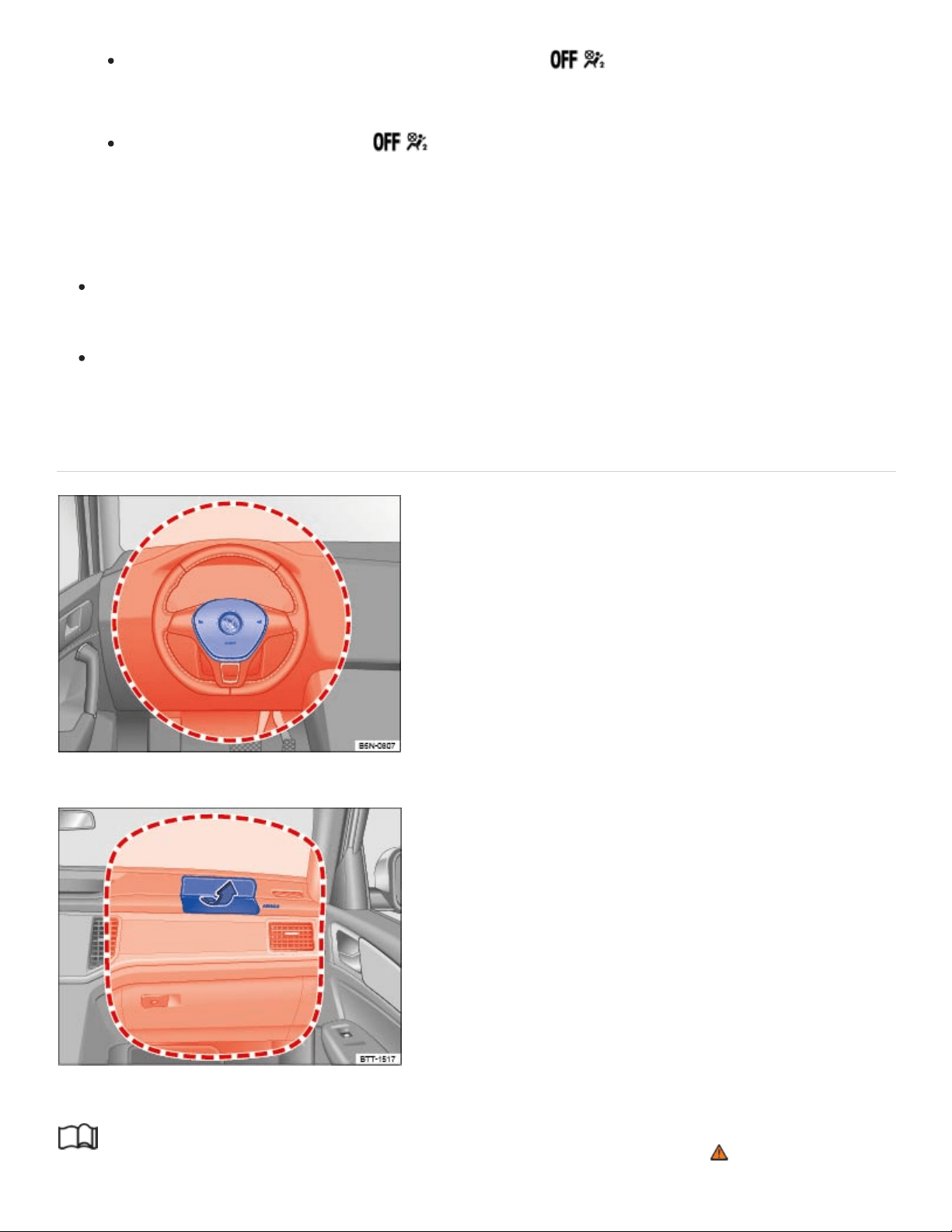
Always make sure that the PASSENGERAIRBAG light comes on and stays on
all the time whenever the ignition is switched on.
If the PASSENGERAIRBAG light does not come on and stay on, immediately in‐
stall the forward-facing child restraint in a seating position on the rear seat and have the
airbag system inspected by an authorized Volkswagen dealer or an authorized
Volkswagen Service Facility.
Always buckle the child restraint firmly in place even when no child is sitting in it. A loose child
restraint can fly around the vehicle during a sudden stop or in a collision.
Always read and heed all WARNINGS whenever using a child restraint in the vehicle: ⇒Safety
belts , ⇒Airbag system , and ⇒Child safety and child restraints .
Front airbags
Fig.32Location and deployment zone of the driver front airbag.
Fig.33Location and deployment zone of the front passenger front airbag.
Read and follow the introductory information and safety information first⇒ Introduction to the
subject

The vehicle is equipped with an Advanced Airbag System in compliance with the United States
Federal Motor Vehicle Safety Standard (FMVSS)208 or the Canada Motor Vehicle Safety Standard
(CMVSS)208 applicable at the time your vehicle was manufactured. The airbag for the driver is in the
steering wheel hub ⇒Fig.32 and the airbag for the front passenger is in the instrument panel
⇒Fig.33 . The general location of the airbags is marked AIRBAG.
The safety belts for the front seating positions have safety belt pretensioners which help take up slack
in the belts. The airbag control unit also activates the belt pretensioners ⇒Airbags and how they
work .
The safety belts also have belt load limiters to reduce the forces acting on a body during an accident.
The areas marked in red (dotted lines) ⇒Fig.32 and ⇒Fig.33 indicate the airbag deployment zone.
Never place or attach accessories or other objects (such as cup holders, telephone brackets, note
pads, navigation systems, large, heavy or bulky objects) on the doors, on the windshield, over or near
the area marked in red (dotted lines).
Front airbags will not deploy:
if the ignition is switched off when a crash occurs,
in side collisions,
in rear-end collisions,
in rollovers,
when the crash deceleration measured by the airbag system is less than the minimum threshold
needed for airbag deployment as registered by the electronic control unit.
The front passenger front airbag will also not deploy:
when the front passenger seat is not occupied,
when the electrical capacitance measured by the capacitive passenger detection system for the
front passenger seat indicates that the passenger side front airbag must be switched off by the
electronic control unit (the PASSENGERAIRBAG light comes on and stays on ⇒Airbags
and how they work ).
DANGER!
Children on the front seat of any vehicle, even one with Advanced Airbags, can be seriously in‐
jured or even killed when an airbag inflates.

A child in a rearward-facing child restraint installed on the front passenger seat will be seri‐
ously injured and can be killed if the front airbag inflates.
The inflating airbag will hit the child restraint or infant carrier with great force and will smash
the child restraint and the child against the seat backrest, center armrest, door, or roof.
Always install rearward-facing child restraints on the rear seat.
Although the Advanced Airbag System in your vehicle is designed to turn off the front airbag
when a rearward-facing child restraint has been installed on the front passenger seat, nobody
can absolutely guarantee that deployment is impossible in all conceivable situations that may
happen during the useful life of your vehicle.
If you have, in exceptional circumstances, nevertheless decided to install a rearward-facing
child restraint on the front passenger seat and the PASSENGERAIRBAG light does
not come on and stay on whenever the ignition is on, immediately install the rearward-facing
seat in a rear seating position and have the airbag system inspected immediately by an autho‐
rized Volkswagen dealer or an authorized Volkswagen Service Facility.
DANGER!
A front seat passenger, especially an infant or small child, will be seriously injured and can even
be killed if too close to the airbag when it deploys – even an Advanced Airbag.
All vehicle occupants and especially children must be restrained properly whenever riding in a
vehicle. An unrestrained or improperly restrained child could be injured by striking the interior
or by being ejected from the vehicle during a sudden maneuver or impact. An unrestrained or
improperly restrained child is also at greater risk of injury or death through contact with an in‐
flating airbag.
Accident statistics show that children are safer on the rear seat than on the front seat.
A suitable child restraint properly installed and used at one of the rear seating positions pro‐
vides the highest degree of protection for infants and small children in most accident
situations.
An Advanced Airbag System can deploy with the low risk option for 3to 6year-old children
when a child who is heavier than the combined capacitance of a typical 1year-old child plus
child restraint is secured on the passenger seat in a forward-facing or rear-facing child re‐
straint that was used to certify your vehicle, and when the other conditions for airbag deploy‐
ment are met.

For their own safety, all children, especially those 12years and younger, must always sit on
the back seat, properly restrained for their age and size.
When installing a child restraint, always carefully follow the manufacturer's instructions.
If the airbag indicator light goes on while driving, have the system inspected immediately by
your authorized Volkswagen dealer or authorized Volkswagen Service Facility. A lit indicator
light means the airbags may not work properly if activated in a crash.
Always make sure that the status signaled by the PASSENGERAIRBAG light is cor‐
rect for the way that the front passenger seat is being used.
WARNING
Objects between you and the airbag will increase the risk of injury in a crash by interfering with
the way the airbag unfolds and/or by being pushed into you as the airbag inflates.
Never hold things in your hands or on your lap when the vehicle is moving.
Never place accessories or other objects (such as cup holders, telephone brackets, notepads,
navigation systems, or things that are large, heavy, or bulky) on the doors or attach them to
the doors; never place them over or near the area marked AIRBAG on the steering wheel, in‐
strument panel, or seat backrests, or between those areas and someone in the vehicle
⇒Fig.32 and ⇒Fig.33 . Such objects could cause serious injury in a collision, especially if an
airbag inflates.
Never attach accessories to the windshield above the passenger front airbag, such as GPS
navigation units or music players. Such objects could cause serious injury in a collision, espe‐
cially if an airbag inflates.
Never recline the front passenger seat to transport objects. Items can also move into the de‐
ployment area of the side airbags or the front airbag during braking or in a sudden maneuver.
Objects near the airbags can fly dangerously through the passenger compartment and cause
injury, particularly when the seat is reclined and the airbags inflate.
Always make sure that there is nothing on the front passenger seat that will cause the capaci‐
tive passenger detection system in the seat to signal to the Airbag System that the seat is oc‐
cupied by a person when it is not, or to signal that it is occupied by someone who is heavier
than the person actually sitting on the seat. The presence of an object could cause the pas‐
senger front airbag to be turned on when it should be off, or could cause the airbag to work in
a way that is different from the way it would have worked without the object on the seat.

Always make sure that nothing is on the front passenger seat when the backrest is folded
forward.
Always make sure that the status signaled by the PASSENGERAIRBAG light is cor‐
rect for the way that the front passenger seat is being used.
WARNING
Holding the steering wheel the wrong way can cause serious injuries to the hands, arms, and
head if the driver's airbag inflates.
Always hold the steering wheel with both hands on the outside of the steering wheel rim at the
9o'clock and 3o'clock positions to help reduce the risk of personal injury if the driver's airbag
inflates.
Never hold the steering wheel at the 12o'clock position or with your hands anywhere inside
the steering wheel or on the steering wheel hub. Holding the steering wheel the wrong way in‐
creases the risk of severe injury to the arms, hands, and head if the driver airbag deploys.
WARNING
The fine dust created when airbags deploy can cause breathing problems for people with asthma
or other breathing conditions.
To reduce the risk of breathing problems, those with asthma or other respiratory conditions
should get fresh air right away by getting out of the vehicle or opening windows or doors.
If you are in a collision in which airbags deploy, wash your hands and face with mild soap and
water before eating.
Be careful not to get the dust into your eyes, or into any cuts, scratches, or open wounds.
If the residue should get into your eyes, flush them with water.
WARNING
Airbags that have deployed in a crash must be replaced.
Use only original equipment airbags approved by Volkswagen and installed by a trained tech‐
nician who has the necessary tools and diagnostic equipment to properly replace any airbag
on your vehicle and assure system effectiveness in a crash.
Never permit salvaged or recycled airbags to be installed in your vehicle.

Undeployed airbag modules and safety belt pretensioners are classified as Perchlorate
Material. Special handling may apply – see http://www.dtsc.ca.gov/hazardouswaste/perchlorate.
Obey all applicable legal requirements regarding handling and disposal of the vehicle or parts of
its restraint system, including airbag modules and safety belts with pretensioners. Authorized
Volkswagen dealers and authorized Volkswagen Service Facilities are familiar with the require‐
ments, and we recommend that you have them perform this service for you.
Advanced Airbag System components
Read and follow the introductory information and safety information first⇒ Introduction to the
subject
The front passenger seat in your vehicle has a lot of very important parts of the Advanced Airbag
System in it ⇒Airbags and how they work . These parts include the capacitive passenger detection
system, wiring, brackets, and more. The control unit monitors the system in the front passenger seat
when the ignition is switched on and turns the airbag indicator light on when a malfunction in the one
of the system components is detected ⇒Monitoring the Advanced Airbag System . Because the front
passenger seat contains important parts of the Advanced Airbag System, you must take care to pre‐
vent it from being damaged. Damage to the seat may prevent the Advanced Airbag System for the
front passenger seat from doing its job in a crash.
The front Advanced Airbag System also includes:
Crash sensors in the front of the vehicle that measure vehicle acceleration/deceleration to provide
information to the Advanced Airbag System about the severity of the crash.
An electronic control unit, with integrated crash sensors for front and side impacts. The control
unit decides whether to fire just the front airbags based on the information received from the crash
sensors. The control unit also decides whether the safety belt pretensioners should be activated.
An Advanced Airbag with gas generator for the driver inside the steering wheel hub.
An Advanced Airbag with gas generator inside the instrument panel for the front passenger.
A capacitive passenger detection system underneath the front passenger seat cover. This system
measures the electrical capacitance of the person in the seat. The information registered is sent
continuously to the electronic control unit to regulate deployment of the front Advanced Airbag on
the passenger side.
An airbag system indicator light in the instrument cluster ⇒Monitoring the Advanced Airbag
System .

The PASSENGERAIRBAG light in the center of the instrument panel that tells you when
the front Advanced Airbag System on the passenger side has been turned off
⇒PASSENGERAIRBAG light .
A switch in the safety belt buckle for the driver and for the front seat passenger that senses
whether that safety belt is latched or not and transmits this information to the electronic control
unit.
WARNING
An airbag system and safety belt pretensioner that are not working properly cannot provide sup‐
plemental protection in a frontal crash.
If the airbag indicator light comes on, it means that there may be something wrong with the
airbag system. It is possible that the airbag will inflate when it is not supposed to, or will not in‐
flate when it should.
Have the airbag system inspected immediately by your authorized Volkswagen dealer or au‐
thorized Volkswagen Service Facility.
Use only original equipment airbags approved by Volkswagen. Have them installed by a
trained technician who has the necessary tools and diagnostic equipment to properly replace
any airbag in your vehicle and assure system effectiveness in a crash.
Never permit salvaged or recycled airbags to be installed in your vehicle.
WARNING
Damage to the front passenger seat can prevent the front airbag from working properly.
Improper repair or disassembly of the front passenger and driver seat can prevent the
Advanced Airbag System from working properly.
Repairs to the front passenger seat should be performed by an authorized Volkswagen dealer
or an authorized Volkswagen Service Facility.
Never remove the front passenger seat or driver seat from the vehicle.
Never remove the upholstery from the front passenger seat.
Never disassemble or take parts off the seat or disconnect wires from it.
Never carry sharp objects in your pockets or put them on the seat. If the capacitive passenger
detection system in the front passenger seat is punctured it cannot work properly.

Never carry things on your lap or carry objects on the front passenger seat. Such objects can
influence the capacitance registered by the capacitive passenger detection system, so that in‐
correct information is provided to the airbag control unit. These things can also cause serious
personal injury if the airbag inflates.
Never store items under the front seats. Parts of the Advanced Airbag System under the front
seats could be damaged, preventing them and the airbag system from working properly.
Never put seat covers or replacement upholstery on the front seats that have not been ap‐
proved by Volkswagen for your specific vehicle.
Seat covers can prevent the Advanced Airbag System from recognizing child restraints or oc‐
cupants on the passenger seat and prevent the side airbag in the seat backrest from deploying
properly.
Never use cushions, pillows, blankets, or similar items on the front passenger seat. The addi‐
tional layers prevent the capacitive passenger detection system from accurately measuring the
capacitance of the child and/or the person on the seat and thus keep the Advanced Airbag
System from working properly.
Never place or use any electrical device (such as a laptop, CD player, or electronic games de‐
vice) on the front passenger seat. Such devices can influence the capacitance registered by
the capacitive passenger detection system, so that incorrect information is provided to the
airbag control unit.
If a seat heater has been retrofitted or otherwise added to the front passenger seat, never in‐
stall any child restraint system on this seat.
If you must use a child restraint on the front passenger seat and the child restraint
manufacturer's instructions require the use of a towel, foam cushion or something similar to
properly position the child restraint, make certain that the PASSENGERAIRBAG light
comes on and stays on whenever the child restraint is installed on the front passenger seat.
If the PASSENGERAIRBAG light does not come on and stay on, immediately install
the child the restraint at a seating position on the rear seat and have the airbag system in‐
spected by your authorized Volkswagen dealer or authorized Volkswagen Service Facility.
WARNING
If the front passenger seat gets wet, dry it immediately.
If liquid soaks into the front passenger seat, this can keep the airbag system from working
properly and may, for instance, deactivate the passenger front airbag. If this happens, the

PASSENGERAIRBAG light will come on and stay on together with the airbag indicator
light in the instrument cluster.
If liquid is pooled on the seat, but has not soaked in, this may also keep the airbag system
from working properly and cause the front passenger front airbag to be enabled (turned on),
even though there is a properly installed child restraint system on the seat. Wet towels or other
wet things on the seat cushion can have the same effect. The PASSENGERAIRBAG
light goes out when the front passenger's front airbag is active.
NOTE
To help prevent damage to electrical and other parts in the seat, do not kneel on the front
seats or apply concentrated pressure to a small area of the seat or backrest.
Never install leather upholstery on a vehicle that originally had cloth upholstery. Never install
cloth upholstery on a vehicle that originally had leather upholstery. The capacitive passenger
detection system for the Advanced Airbag system will not work properly if different upholstery
is installed on the passenger seat than the upholstery originally installed on the vehicle when it
was originally manufactured.
How to tell if the front passenger front airbag is on or off
Read and follow the introductory information and safety information first⇒ Introduction to the
subject
Passenger front airbag
Regardless of safety belt use, the airbag in front of the front passenger seat will be switched off if the
electrical capacitance measured on this seat is less than the value programmed in the electronic con‐
trol unit.
The front airbag on the passenger side of the front seat will also be turned off if the electrical capaci‐
tance measured on the seat (by the capacitive passenger detection system) is less than or equal to
the combined capacitance of:
a typical 1year-old infant and
any of the child restraints listed in Federal Motor Vehicle Safety Standard208 for which the
Advanced Airbag System in your vehicle is certified.

For a listing of the child restraints that were used to certify your vehicle's compliance with U.S. Safety
Standard208, see ⇒Child restraints and the Advanced Airbag System . The PASSENGERAIRBAG
light comes on and stays on to tell you when the front Advanced Airbag on the passenger side
has been turned off.
Passenger front airbag active
Switch on the ignition.
The capacitive passenger detection system measures the electrical capacitance of the front pas‐
senger seat. If that capacitance is above the reference value, the passenger front airbag will be
switched on by the Advanced Airbag control unit.
If the ignition is on, and the PASSENGERAIRBAG light in the instrument panel does not
come on, the passenger front airbag is generally active. If the light has burned out (see be‐
low), you will be unable to tell whether the passenger front airbag is active or not.
Using child restraints on the front passenger seat
The airbag on the front passenger side makes the front seat a potentially dangerous place for a child
to ride. Because of this danger, and because children are generally better protected on the rear seat
when properly restrained for their age and size, we strongly advise that you always place children on
the rear seat ⇒The dangers of using child restraints on the front seat . For a list of the child restraints
used to certify compliance of the Advanced Airbag System in your vehicle with the suppression re‐
quirements of FMVSS208, see ⇒Child restraints and the Advanced Airbag System .
For more information, see ⇒Child safety and child restraints ; note ⇒ below!
How do I know when the passenger front airbag has been turned off by the control unit?
The PASSENGERAIRBAG light in the instrument panel will come on and stay on to tell you
when the front Advanced Airbag on the passenger side has been turned off by the electronic control
unit. Unless the yellow light comes on and stays on, the passenger front airbag is still active
⇒PASSENGERAIRBAG light .
For safety reasons, you must never use a child restraint system on the front passenger seat un‐
less the PASSENGERAIRBAG light comes on and stays on, perhaps in combination with
the indicator light in the instrument cluster. If the passenger front airbag deployed in an accident, it
would severely injure and possibly kill the child in the restraint system. If the PASSENGERAIRBAG
light burns out, the airbag indicator light will come on and signal a malfunction of the Advanced
Airbag System. Although the burned-out light will not change the way the front airbag on the passen‐

ger side works, it will no longer be possible to use the PASSENGERAIRBAG light to make
sure that the airbag on/off status is correct for the occupant on the front passenger seat. Have the
airbag system inspected immediately by your authorized Volkswagen dealer or authorized
Volkswagen Service Facility.
DANGER!
A front seat passenger, especially an infant or small child, will be seriously injured and can even
be killed if sitting too close to the airbag when it deploys.
All vehicle occupants and especially children must be restrained properly whenever riding in a
vehicle. An unrestrained or improperly restrained child could be injured by striking the interior
or by being ejected from the vehicle during a sudden maneuver or impact. An unrestrained or
improperly restrained child is also at greater risk of injury or death through contact with an in‐
flating airbag.
A child in a rearward-facing child restraint installed on the front passenger seat will be seri‐
ously injured and can be killed if the front airbag inflates.
The inflating airbag will hit the child restraint or infant carrier with great force and will smash
the child restraint and the child against the seat backrest, center armrest, door, or roof.
Accident statistics show that children are safer on the rear seat than on the front seat.
A suitable child restraint properly installed and used at one of the rear seating positions pro‐
vides the highest degree of protection for infants and small children in most accident
situations.
For their own safety, all children, especially 12years and younger, must always ride on the
back seat properly restrained for their age and size.
When installing a child restraint, always carefully follow the manufacturer's instructions.
WARNING
To reduce the risk of serious injury, make sure that the PASSENGERAIRBAG light
comes on and stays on whenever a child restraint is installed on the front passenger seat and the
ignition is switched on. Take the child restraint off the front passenger seat and install it properly
at one of the seating positions on the rear seat if the PASSENGERAIRBAG light does not
stay on. Have the airbag system inspected immediately by an authorized Volkswagen dealer or
an authorized Volkswagen Service Facility.

If you must use a child restraint on the front passenger seat and the child restraint
manufacturer's instructions require the use of a towel, foam cushion or something similar to
properly position the child restraint, make certain that the PASSENGERAIRBAG light
comes on and stays on whenever the child restraint is installed on the front passenger seat.
Otherwise, install the child restraint system on the rear seat!
WARNING
Changes in the electrical capacitance of the passenger seat while driving can switch the passen‐
ger front airbag on or off so that it does not deploy when it should or deploys when it should not,
resulting in an increased risk of serious personal injury.
Do not carry anything on your lap or transport things on the passenger seat. Things on the
passenger seat can influence the capacitance registered by the capacitive passenger detec‐
tion system, sending the wrong information to the airbag control unit. These objects can also
cause serious personal injury if the airbag inflates.
Always make sure that a child restraint has been correctly registered by the capacitive passen‐
ger detection system. If the status of the Advanced Airbag System changes while the vehicle
is moving, the PASSENGERAIRBAG light blinks for about 5seconds to catch the
driver's attention. If this happens, always stop as soon as it is safe to do so and check to make
sure that the airbag on/off status is correct for the passenger riding on the front passenger
seat.
Side airbags
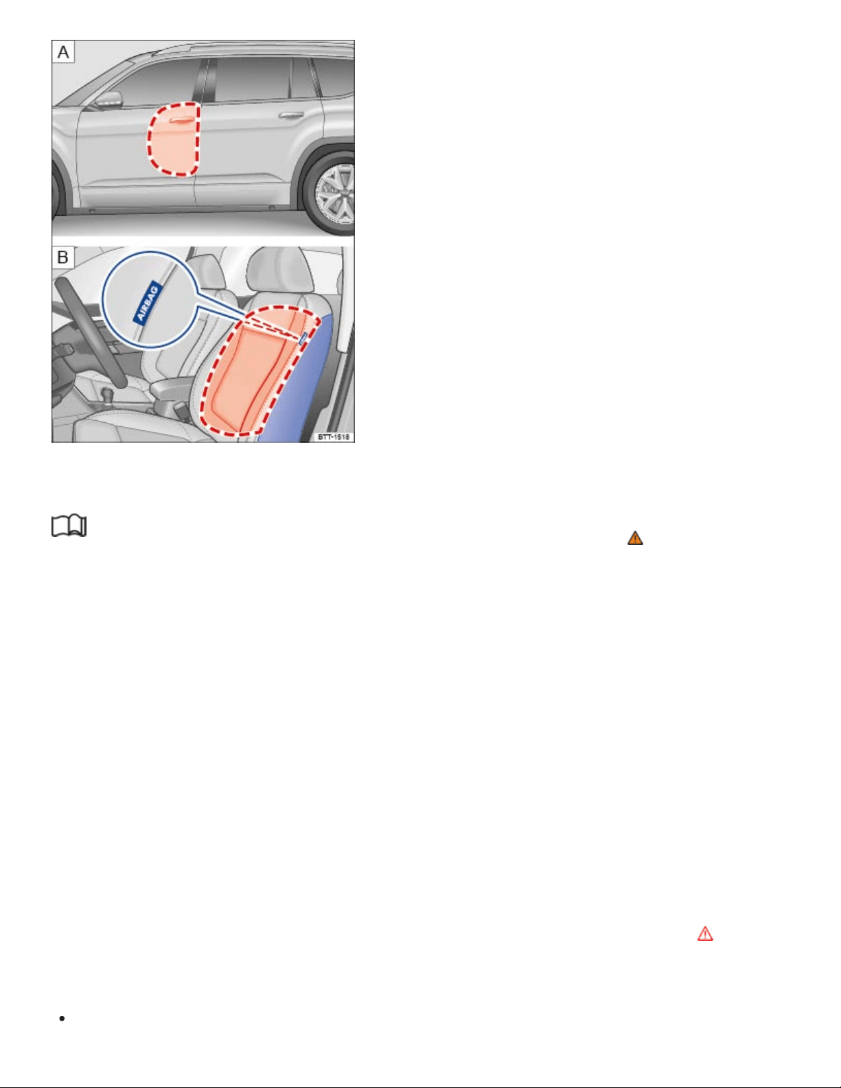
Fig.34On the driver side. : Location and deployment zone of the side airbags. : Location and deploy‐
ment zone of the side airbags in the padding on the outboard side of the front seat backrests.
Read and follow the introductory information and safety information first⇒ Introduction to the
subject
The side airbags are in the backrest padding of the driver and passenger seats ⇒Fig.34 . The gen‐
eral location is shown by the word AIRBAG. The area marked in red (dotted lines) indicates the de‐
ployment zone of the side airbags.
In a side collision, the side airbag in the seat backrest can deploy on the side of the vehicle that is
struck and help reduce the risk of injury to the driver or the front seat passenger.
The side airbags installed for the front seating positions have been designed and certified to help re‐
duce the risk of injury that can be caused by airbags when they inflate, particularly when the occupant
sitting next to it is not seated properly.
The side airbag for the front passenger seat can be used with properly installed child restraints.
Always read and heed all important information and WARNINGS whenever using a child restraint in
the vehicle: ⇒Safety belts , ⇒Airbag system , ⇒Child safety and child restraints , and ⇒ .
The side airbag system includes:
An electronic control module and side impact sensors.

Side airbags in the front seat backrests.
An airbag system indicator light in the instrument cluster ⇒Monitoring the Advanced Airbag
System .
When a side airbag deploys in a collision, a gas generator fills the side airbag between the vehicle oc‐
cupant and the door. The side airbag system supplements the safety belts and can help to reduce the
risk of injury to the occupant's upper torso.
In order to help provide this additional protection, the side airbag must inflate within the blink of an
eye at very high speed and with great force. The supplemental side airbag could injure you if your
seating position is not proper or upright or if items are in the area where the supplemental side airbag
inflates. This applies especially to children ⇒Child safety and child restraints .
The airbag system is monitored electronically to make sure it is working properly at all times. Every
time you turn on the ignition, the airbag system indicator light will come on for a few seconds
(function check).
The airbag system is not a substitute for your safety belt. Rather, it is part of the overall occupant re‐
straint system in your vehicle ⇒Sitting properly and safely , ⇒Safety belts .
It is important to remember that the side airbag system is designed to help reduce the likelihood of
serious injury. However, it is also important to remember that a deploying airbag may also cause
other injuries, such as swelling, bruising, friction burns, and abrasions. Also remember that side
airbags will deploy only once and only in certain kinds of accidents. After the side airbag inflates, the
system must be replaced. Your safety belts are always there to offer protection in those accidents in
which side airbags are not supposed to deploy or when they have already deployed.
The side airbag system will not inflate:
if the ignition is switched off when a crash occurs,
in side collisions when the acceleration measured by the sensor is too low,
in front-end collisions,
in rear-end collisions,
in rollovers, unless the deployment threshold for deployment stored in the control unit is met.
In some types of accidents, the front airbags, Side Curtain Protection airbags and side airbags may
be triggered together.
WARNING
®

An inflating side airbag can cause serious or even fatal injury. Improperly wearing safety belts
and improper seating positions increase the risk of serious personal injury and death whenever a
vehicle is being used.
To help reduce the risk of injury when the supplemental side airbag inflates,
Always sit in an upright position and do not lean against the area where the side airbag
is located.
Never let a child or anyone else rest their head against the side trim panel in the area
where the side airbag inflates.
Always make sure that safety belts are worn correctly.
Never let anyone sitting in the front seat put their hand out of the window.
Objects between you and the airbag can increase the risk of injury in a collision by interfering
with the way the airbag unfolds or by being pushed into you as the airbag inflates.
Never place or attach accessories or other objects (such as cup holders, telephone brackets,
or even large, bulky objects) on the doors or over or near the area marked AIRBAG on the
seat backrests ⇒Fig.34 .
Accessories or other objects can fly dangerously through the passenger compartment and
cause serious injury if the supplemental side airbag inflates.
Never position or hold any objects or pets in the area where an airbag inflates or allow any
children or other passengers to ride in that space.
Never use the built-in coat hooks for anything but lightweight clothing. Never leave any heavy
or sharp-edged objects in the pockets. Such objects may interfere with side airbag deployment
and cause serious personal injury in a collision.
WARNING
Improper use, repair, or disassembly of the driver and front passenger seats can prevent side
airbags from working properly and result in severe injuries.
Always make sure that the side airbag can inflate without interference:
Never install seat covers or replacement upholstery over the front seat backrests that
have not been specifically approved by Volkswagen. Otherwise, the side airbag may not
be able to deploy properly.
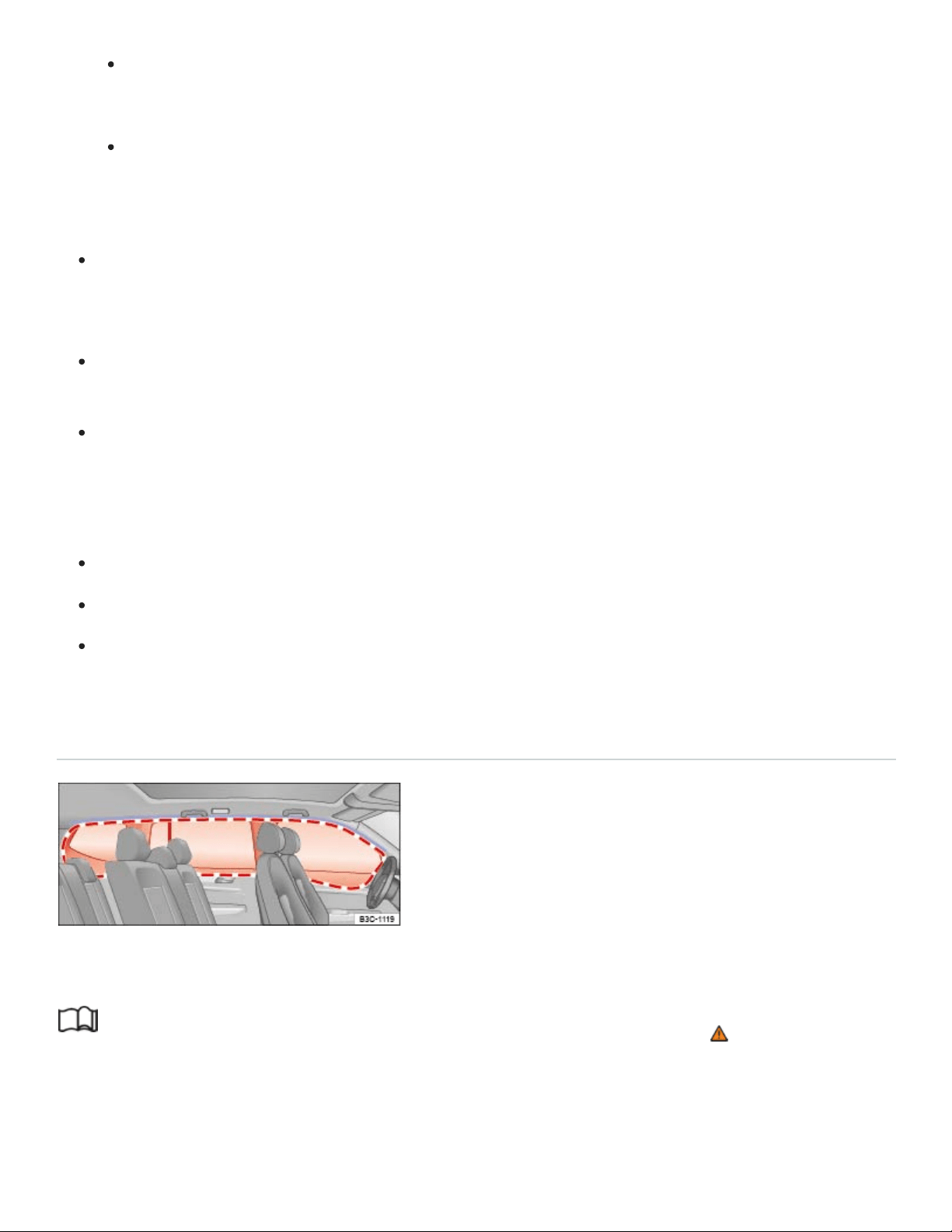
Never put seat cushions, blankets, or other coverings over the areas where the side
airbags inflate.
Damage to the original seat covers or to the seam in the area of the side airbag module
must always be repaired immediately by an authorized Volkswagen dealer or authorized
Volkswagen Service Facility.
Always prevent the side airbags from being damaged by heavy objects hitting the sides of the
seat backrests or force being put on the seat backs, especially in the area where the side
airbag module is located.
The airbag system can only be triggered once. If the airbag has been triggered, the system
must be replaced.
Always have work involving the side airbag system, including removal, replacement, and in‐
stallation of airbag components, or other repairs performed by an authorized Volkswagen
dealer or authorized Volkswagen Service Facility. Otherwise, the airbag system may not work
correctly.
Never remove the front seats from the vehicle or modify parts of the front seats.
Never attempt to modify any components of the airbag system in any way.
If too much force is exerted on the seat backrest bolsters, the side airbags may deploy improp‐
erly, not at all, or when they should not.
Side Curtain Protection airbags
Fig.35On the left vehicle side: Installation location and deployment zone of the Side Curtain
Protection airbag.
Read and follow the introductory information and safety information first⇒ Introduction to the
subject
The Side Curtain Protection airbags are in the header area on both sides of the vehicle ⇒Fig.35 .
The general location is identified by the word AIRBAG. The red lines show the deployment zone of
the Side Curtain Protection airbags. The Side Curtain Protection airbags contain features that pro‐
®
®
®

vide ejection mitigation to help prevent vehicle occupants or parts of their bodies from being com‐
pletely or partially ejected from the vehicle interior in certain side impacts and vehicle rollovers.
The Side Curtain Protection airbag system includes:
An electronic control module and side impact sensors.
The Side Curtain Protection airbags above the front and rear side windows.
An airbag system indicator light in the instrument cluster ⇒Monitoring the Advanced Airbag
System .
The Side Curtain Protection airbags inflate downwards between the occupant and the side window
on that side of the vehicle that is struck in certain side collisions ⇒Fig.35 . The Side Curtain
Protection airbag system supplements the safety belts and can help to reduce the risk of injury to
the occupant's head and upper torso on the side of the vehicle that is struck in a side collision. The
Side Curtain Protection airbags also contain features to help prevent vehicle occupants or parts of
their bodies from being completely or partially ejected from the vehicle interior in certain vehicle
rollovers.
In order to help provide this additional protection, the Side Curtain Protection airbag must inflate
within the blink of an eye at very high speed and with great force. The Side Curtain Protection airbag
could injure you if your seating position is not proper or upright or if items are in the area where the
supplemental Side Curtain Protection airbag inflates. This applies especially to children ⇒Child
safety and child restraints .
The airbag system is monitored electronically to make sure it is working properly at all times. Every
time you turn on the ignition, the airbag system indicator light will come on for a few seconds
(function check).
The airbag system is not a substitute for your safety belt. Rather, it is part of the overall occupant re‐
straint system in your vehicle ⇒Sitting properly and safely , ⇒Safety belts .
It is important to remember that the Side Curtain Protection airbag system is designed to help re‐
duce the likelihood of serious injury. However, it is possible that a deployed Side Curtain Protection
airbag may cause other injuries such as swelling, bruising, friction burns, and abrasions. Remember
too, Side Curtain Protection airbags will deploy only once and only in certain kinds of accidents. Side
Curtain Protection airbags that have deployed in a crash must be replaced. Your safety belts are al‐
ways there to offer protection in those accidents in which Side Curtain Protection airbags are not
supposed to deploy or when they have already deployed.
The Side Curtain Protection airbag will not inflate:
®
®
®
®
®
®
®
®
®
®
®
®
®
®

if the ignition is switched off when a crash occurs,
in side collisions when the acceleration measured by the sensor is too low,
in front-end collisions,
in rear-end collisions,
in rollovers, unless the deployment threshold for deployment stored in the control unit is met.
In some types of accidents, the front, Side Curtain Protection and side airbags may be triggered
together.
WARNING
An inflating Side Curtain Protection airbag can cause serious or even fatal injury. Improperly
wearing safety belts and improper seating positions increase the risk of serious personal injury
and death whenever a vehicle is being used.
A deploying airbag inflates within a fraction of a second with a lot of force and at very high
speed.
Always make sure that the Side Curtain Protection airbag can inflate without interference.
Always sit in proper seating position and wear safety belts while traveling so that the Side
Curtain Protection airbags can help provide protection.
Never let occupants place any parts of their bodies in the area where the Side Curtain
Protection airbag inflates.
Always keep the area where the Side Curtain Protection airbag inflates clear. Never carry any
objects or pets in the area between them and where the airbags inflate and never let children
or other passengers ride in this area.
Never use hangers to hang clothes on the hooks.
Never use the built-in coat hooks for anything but lightweight clothing. Never leave any heavy
or sharp-edged objects in the pockets that may interfere with airbag deployment and can
cause personal injury in a collision.
Only use factory-installed sunshades or, if shades installed after the vehicle leaves the factory,
use only genuine Volkswagen sunshades.
Never swing the sun visors over to the side windows if things such as pens, garage door open‐
ers, hands-free speakers, etc. are attached to the sun visors. They could come loose and
cause serious injury if the Side Curtain Protection airbag inflates.
®
®
®
®
®
®
®

WARNING
The airbag system can only be triggered once.
If the airbag has been triggered, the system must be replaced by an authorized Volkswagen
dealer or authorized Volkswagen Service Facility.
Always have work involving the curtain airbag system, removal and installation of the airbag
components, or other repairs performed by your authorized Volkswagen dealer or authorized
Volkswagen Service Facility. Otherwise the airbag system may not work correctly.
Never attempt to modify any components of the airbag system in any way.
Never attach objects to the cover or in the deployment zone of a Side Curtain Protection
airbag.
Always make sure that the airbag deployment zones are clear at all times. Never let anything
or object, a pet, or a person, including an infant or small child, be in the space between any
vehicle occupant and any airbag.
Do not attach any accessories to the doors.
Child safety and child restraints
Introduction to the subject
In this chapter you will find information on the following subjects:
⇒Child restraints – Overview
⇒Child restraints and the Advanced Airbag System
⇒Important safety instructions for using child restraints
⇒Using a child restraint on the rear seat
⇒Infant seats
⇒Convertible child restraints
⇒Booster seats and safety belts
®

⇒Installing child restraints with a safety belt
⇒Securing the child restraint with LATCH/UAS lower universal anchorages
⇒Securing a child restraint with the Top Tether strap
⇒Sources of information about child restraints and their use
The physical principles of what happens when your vehicle is in a collision or other accident also ap‐
ply to children ⇒Safety belts . But unlike adults and teenagers, their muscles and bones are not fully
developed. In many respects children are at greater risk of serious injury in accidents than are adults.
Because children's bodies are not fully developed, they must use restraint systems especially de‐
signed for their size, weight, and body structure. Many countries and all states of the United States
and provinces of Canada have laws requiring the use of approved child restraint systems for infants
and small children.
In a frontal crash at a speed of 20–35mph (30–56km/h), the forces acting on a 13pound (6kg) in‐
fant will be more than 20times the weight of the child. This means the effective weight of the child
would suddenly increase to more than 260pounds (120kg). Under these conditions, only an appro‐
priate child restraint properly used can reduce the risk of serious injury. Child restraints, like adult
safety belts, must be used properly to be effective. Used improperly, they can increase the risk of seri‐
ous injury in an accident.
All children, especially those 12years and younger, must always ride in the back seat properly re‐
strained for their age and size. If you must install a child restraint on the front passenger seat in ex‐
ceptional circumstances, be sure to read and heed the important information and warnings in the sec‐
tion of this Manual that begins on ⇒Child restraints and the Advanced Airbag System . Infants and
other children who are properly restrained in an appropriate child restraint that is for their size and
age can benefit from the protection that supplemental side airbags provide in some kinds of crashes.
For more information, please see information provided by the:
National Highway Traffic Safety Administration (NHTSA), currently at: http://www.safercar.gov (for
the USA)
Transport Canada Information Centre, currently at: http://www.tc.gc.ca (for Canada)

Consult the child restraint manufacturer's instructions to be sure the seat is right for your child's size
⇒Sources of information about child restraints and their use . Please be sure to read and heed all of
the important information and WARNINGS about child safety, Advanced Airbags, and the installation
of child restraints in this Manual.
There is a lot you need to know about the Advanced Airbags in your vehicle and how they work when
infants and children in child restraints are on the front passenger seat. Because of the large amount
of important information, we cannot repeat it all here. We urge you to read the detailed information in
this Manual about airbags and the Advanced Airbag System in your vehicle and the very important in‐
formation about transporting children on the front passenger seat. Please be sure to heed the
WARNINGS - they are extremely important for your safety and the safety of your passengers, espe‐
cially infants and small children.
DANGER!
Children on the front seat of any car, even with Advanced Airbags, can be seriously injured or
even killed when an airbag inflates.
A child in a rearward-facing child restraint installed on the front passenger seat will be seri‐
ously injured and can be killed if the front airbag inflates.
The inflating airbag will hit the child restraint or infant carrier with great force and will smash
the child restraint and child against the backrest, center armrest, door or roof.
Always install rearward-facing child restraints on the rear seat.
If you have, in exceptional circumstances, nevertheless decided to install a rearward-facing
child restraint on the front passenger seat and the PASSENGERAIRBAG light does
not come on and stay on whenever the ignition is on, immediately install the rearward-facing
child restraint on the rear seat and have the airbag system inspected right away by your autho‐
rized Volkswagen dealer or authorized Volkswagen Service Facility.
WARNING
Accident statistics have shown that children are generally safer in the rear seat area than in the
front seating position. Always restrain any child age12 and under in the rear.
All vehicle occupants and especially children must be restrained properly whenever riding in a
vehicle. An unrestrained or improperly restrained child could be injured by striking the interior
or by being ejected from the vehicle during a sudden maneuver or impact. An unrestrained or

improperly restrained child is also at greater risk of injury or death through contact with an in‐
flating airbag.
A suitable child restraint properly installed and used at one of the rear seating positions pro‐
vides the highest degree of protection for infants and small children in most accident
situations.
WARNING
Forward-facing child restraints installed on the front passenger seat may interfere with the de‐
ployment of the airbag and cause serious personal injury to the child.
If exceptional circumstances require the use of a forward-facing child restraint on the front
passenger's seat, the child's safety and well-being require the following special precautions to
be taken:
Always make sure that the forward-facing seat has been designed and certified by its
manufacturer for use on a front passenger seat with a front and side airbag.
Always carefully follow the manufacturer's instructions provided with the child restraint or
infant carrier.
Never install a child restraint without a properly attached top tether strap if the child re‐
straint manufacturer's instructions require the top tether strap for proper installation, or if
required by law. For example, the use of a top tether strap for forward-facing child re‐
straints is required by law in Canada.
Never put the forward-facing child restraint up against or very near the instrument panel.
Always set the safety belt upper anchorage to the adjustment position that permits
proper installation in accordance with the child restraint manufacturer's instructions.
Always move the front passenger seat to the highest position in the up and down adjust‐
ment range and move it back to the rearmost position in the seat's fore and aft adjust‐
ment range, as far away from the airbag as possible before installing the forward-facing
child restraint.
Always make sure that the safety belt upper anchorage is behind the child restraint and
not next to or in front of the child restraint so that the safety belt will be properly
positioned.

Always make sure that nothing is in the way that prevents the front passenger's seat
from being moved to the rearmost position in its fore and aft adjustment range.
Always make sure that the backrest is in the upright position.
Never place objects on the seat (such as a laptop, CD player, or electronic games de‐
vice). These may influence the electrical capacitance measured by the capacitive pas‐
senger detection system and can also fly around in an accident and cause serious per‐
sonal injury.
If a seat heater has been retrofitted or otherwise added to the front passenger seat,
never install any child restraint system on this seat.
Make sure that there are no wet objects (such as a wet towel) and no water or other liq‐
uids on the front passenger seat cushion.
Always make sure that the PASSENGERAIRBAG light comes on and stays on
all the time whenever the ignition is switched on.
If the PASSENGERAIRBAG light does not come on and stay on, immediately in‐
stall the forward-facing child restraint in a rear seating position and have the airbag sys‐
tem inspected by your authorized Volkswagen dealer or authorized Volkswagen Service
Facility.
Always buckle the child restraint firmly in place even if a child is not sitting in it. A loose child
restraint can fly around during a sudden stop or in a collision.
Always read and heed all WARNINGS whenever using a child restraint in a vehicle. See
⇒Safety belts , ⇒Airbag system , and ⇒Child safety and child restraints .
Always replace child restraints that were installed in a vehicle during a crash. Damage to a child
restraint that is not visible could cause it to fail in another collision situation.
Child restraints – Overview
Read and follow the introductory information and safety information first⇒ Introduction to the
subject

All children and especially infants must be properly restrained in a child restraint appropriate for their
size and age whenever riding in a vehicle. Their safety also requires that the child restraint be prop‐
erly installed. There are many car seat choices on the market. You can use the information below to
help you choose a car seat that best meets your child’s needs.
Type of child restraint Applies to
Rear-facing child restraint
Birth to 12months: Your child under age1 should always ride in
a rear-facing car seat. There are different types of rear-facing car
seats:
– Infant-only seats can only be used rear-facing.
– Convertible and all-in-one car seats typically have higher height
and weight limits for the rear-facing position, allowing you to keep
your child rear-facing for a longer period of time.
Rear-facing child restraint before
moving to a forward-facing child
restraint
1–3years: Keep your child rear-facing as long as possible. It’s
the best way to keep him or her safe. Your child should stay in a
rear-facing car seat until he or she reaches the top height or
weight limit allowed by the car seat’s manufacturer. Once your
child outgrows the rear-facing car seat, your child is ready to travel
in a forward-facing car seat with a harness and tether.

Type of child restraint Applies to
Forward-facing child restraint
4–7years: Keep your child in a forward-facing car seat with a
harness and tether until he or she reaches the top height or weight
limit allowed by the car seat’s manufacturer. Once your child out‐
grows the forward-facing car seat with a harness, it’s time to travel
in a booster seat, but still in the back seat.
Booster seat
7–12years: Keep your child in a booster seat until he or she is
big enough to fit in a safety belt properly. For a safety belt to fit
properly, the lap belt must lie snugly across the upper thighs, not
the stomach. The shoulder belt should lie snugly across the shoul‐
der and chest and not cross the neck or face. Remember: your
child should still ride in the back seat because it’s safer there.
Today's child restraints are designed to be secured to the vehicle either with the standard 3point lap
and shoulder belt or with the LATCH/UAS lower universal anchorages. Many child restraints also re‐
quire the use of a top tether strap. Depending on your state or country, top tether straps may also be
required by law. The top tether strap reduces the forward movement of the child restraint in a crash,
to help reduce the risk of head injury if the child hits the vehicle interior.
Your vehicle has the following installation options in the second and third row of seats
Child restraint installation
Second row of seats (2 or 3 seat‐
ing positions)
Third row of seats (2 seating
positions)

Child restraint installation
Second row of seats (2 or 3 seat‐
ing positions)
Third row of seats (2 seating
positions)
LATCH/UAS lower universal
anchorages
–
Top tether anchorage
Safety belts with the switchable
locking feature
The LATCH/UAS lower universal anchorage attachment points are on the lower part of the sec‐
ond row seat backrests. Each lower universal anchorage point is accessible through an open‐
ing in the backrest upholstery. There are two anchorages for each of the seating positions on
the second row. The circular markings help you to locate the lower anchorages⇒Fig.43 .
Installing 3 child restraints on the second row
With the right combination of child restraints it is possible to install three child restraints on the second
row at the same time. However, some child restraints are wider than others. It is not possible to prop‐
erly install three wide child restraints on the second row at the same time. If you need to install three
child restraints at the same time, always make sure that the child restraints are properly installed.
Be especially careful when installing a child restraint on the center seating position in the second row
as it is narrower than the outboard positions. A wide child restraint installed on the center seat may
cover the safety belt buckles for the other seating positions. Do not allow someone to ride in a seating
position where the safety belt buckle is covered by a child restraint ⇒Safety belts .
A child restraint in the center seating position may also contact or push up against the safety belt
buckles, which can damage the buckles and make them unusable or unsafe. Always check that the
child restraint does not contact any of the safety belt buckles. Check the placement of the child re‐
straint regularly to make sure that it has not shifted and come into contact with any of the safety belt
buckles. Although properly installing the child restraint and regularly checking its placement will help
to prevent damage to the safety belt buckles, installing a protective cover on the buckles will provide
additional protection ⇒Using a child restraint on the rear seat .

How to tell if the child restraint is properly installed
The child restraint is flush with both the seat cushion and the seat backrest, unless a small gap
between the child restraint and the seat backrest is allowed by the child restraint manufacturer.
The child restraint does not hang over the edge of the vehicle seat by more than the generally ac‐
cepted 20% of the child restraint. Always follow the overhang limits.
The child restraint is centered in the seating position and is not installed at an angle.
The child restraint does not move forward or sideways by more than about 1 inch (2.5 cm).
The child restraint does not contact or push against any of the safety belt buckles, because this
can cause damage to the buckles and make the buckles unusable or unsafe.
The child restraints do not interfere with each other and each stays fully functional and accessible
to properly restrain and protect each child.
The child restraint is installed with LATCH/UAS or the vehicle safety belt according to the weight
limits stated on the child restraint and the child restraint’s top tether is used as instructed by the
child restraint manufacturer.
More information:
Important safety instructions for using child restraints ⇒Important safety instructions for using
child restraints
Using a child restraint on the rear seat ⇒Using a child restraint on the rear seat
Infant seats ⇒Infant seats
Convertible child restraints ⇒Convertible child restraints
Booster seats and safety belts ⇒Booster seats and safety belts
Installing child restraints with a safety belt ⇒Installing child restraints with a safety belt
Child restraints and the Advanced Airbag System
Read and follow the introductory information and safety information first⇒ Introduction to the
subject
Advanced front airbag system and children
Your vehicle is equipped with a front Advanced Airbag System that complies with United States
Federal Motor Vehicle Safety Standard (FMVSS)208 and with Canada Motor Vehicle Safety
Standard (CMVSS)208 as applicable at the time your vehicle was manufactured.

The Advanced Airbag System in your vehicle has been certified to meet the low risk requirements for
3to 6year-old children (as defined in the standard) on the passenger side and small adults on the
driver side. Low risk deployment occurs in those crashes that take place at lower decelerations as de‐
fined in the electronic control unit. The low risk deployment criteria are intended to reduce the risk of
injury through interaction with the airbag that can occur in these collisions, for example, by being too
close to the steering wheel or instrument panel when the airbag inflates.
In addition, the system has been certified to comply with the suppression requirements of the Safety
Standard, to turn off the front airbag automatically for infants up to 12months who are restrained on
the front passenger seat in child restraints that are listed in the Standard.
Even though your vehicle is equipped with an Advanced Airbag System, all children, especially those
12years and younger, must always ride in the back seat properly restrained for their age and size.
The airbag on the passenger side makes the front seat a potentially dangerous place for a child to
ride. The front seat is not the safest place for a child in a forward-facing child restraint. It is a very
dangerous place for an infant or a larger child in a rearward-facing seat.
The vehicle's Advanced Airbag System has a capacitive passenger detection system in the front pas‐
senger seat cushion that can detect the presence of a baby or a child in a child restraint system on
this seat.
The capacitive passenger detection system measures the capacitance of the child and the child re‐
straint and a child blanket on the front passenger seat. The capacitance due to the presence of a
child, a child restraint, and a baby blanket on the front passenger seat is related to the child restraint
system resting on the seat. The capacitance of a child restraint system varies depending on the type
of system and specific make and model.
The electrical capacitance of the various types, makes, and models of child restraints specified by the
U.S. National Highway Traffic Safety Administration (NHTSA) in the relevant safety standard are
stored in the Advanced Airbag System control unit together with the capacitances typical of infants
and a 1year-old child. When a child restraint is used on the front passenger seat with a typical
1year-old infant, the Advanced Airbag System compares the capacitance measured by the capacitive
passenger detection system with the data stored in the electronic control unit.
Child restraints and Advanced Airbags
No matter what child restraint you use, make sure that it has been certified to meet U.S. Federal
Motor Vehicle Safety Standard213 (FMVSS213) or, if you live in Canada, Canada Motor Vehicle
Safety Standard213 (CMVSS213). Also make sure that the child restraint you are using has been

certified by its manufacturer for use with an airbag. Always be sure that the child restraint is properly
installed at one of the rear seating positions. If in exceptional circumstances you must use it on the
front passenger seat, carefully read all of the information on child safety and Advanced Airbags and
heed all of the applicable WARNINGS. Make certain that the child restraint is correctly recognized by
the capacitive passenger detection system inside the front passenger seat, that the passenger front
airbag is switched off, and that the airbag status is always correctly signaled by the
PASSENGERAIRBAG light.
Many types and models of child restraints have been available over the years, new models are intro‐
duced regularly incorporating new and improved designs and older models are taken out of produc‐
tion. Child restraints are not standardized. Child restraints of the same type typically have different
weights and sizes and different footprints, the size and shape of the bottom of the child restraint that
sits on the seat, when they are installed on a vehicle seat. These differences make it virtually impossi‐
ble to certify compliance with the requirements for Advanced Airbags with each and every child re‐
straint that has ever been sold in the past or will be sold over the course of the useful life of your
vehicle.
For this reason, the United States National Highway Traffic Safety Administration has published a list
of specific types, makes and models of child restraints that must be used to certify compliance of the
Advanced Airbag System in your vehicle with the suppression requirements of Federal Motor Vehicle
Safety Standard 208. These child restraints are:
Subpart A. Car bed child restraints
Model Manufactured on or after
Angel Guard Angel Ride AA2403FOF September25, 2007
Subpart B. Rear-facing child restraints
Model Manufactured on or after
Century Smart Fit 4543 December1, 1999
Cosco Arriva 22-013 PAW and base 22-999 WHO September25, 2007
Evenflo Discovery Adjust Right 212 December1, 1999

Model Manufactured on or after
Graco Infant 8457 December1, 1999
Graco Snugride September25, 2007
Peg Perego Primo Viaggio SIP IMUN00US September25, 2007
Subpart C. Forward-facing and convertible child restraints
Model Manufactured on or after
Britax Roundabout E9L02xx September25, 2007
Cosco Touriva 02519 December1, 1999
Cosco Summit Deluxe High Back Booster 22-262 September25, 2007
Cosco High Back Booster 22-209 September25, 2007
Evenflo Tribute V 379xxxx September25, 2007
Evenflo Medallion 254 December1, 1999
Evenflo Generations 352xxxx September25, 2007
Graco ComfortSport September25, 2007
Graco Toddler SafeSeat Step 2 September25, 2007
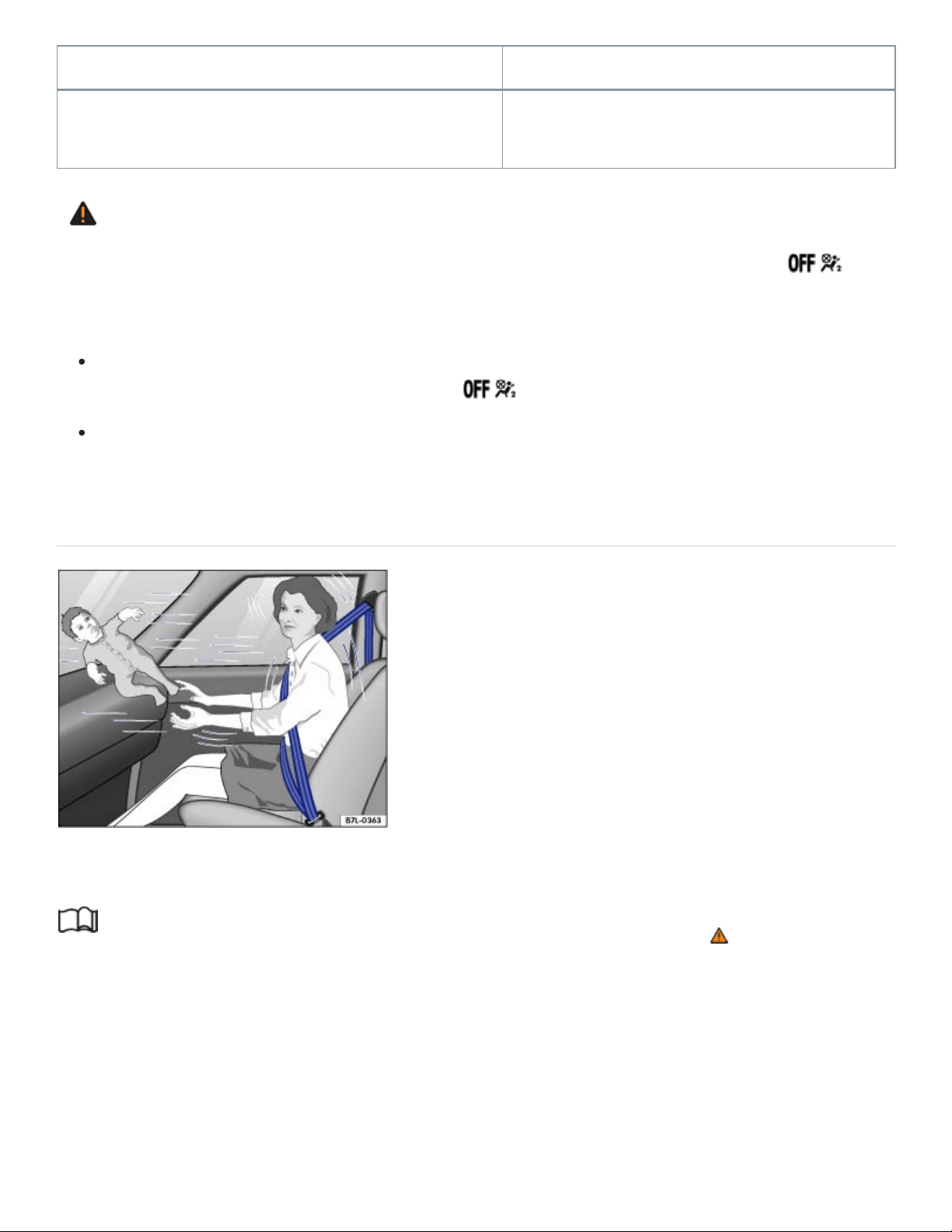
Model Manufactured on or after
Graco Platinum Cargo September25, 2007
WARNING
To reduce the risk of serious injury, always make sure that the PASSENGERAIRBAG
light comes on and stays on whenever a child restraint is installed on the front passenger seat
and the ignition is switched on.
Take the child restraint off the front passenger seat and install it properly at one of the rear
seat positions if the PASSENGERAIRBAG light does not come on and stay on.
Have the airbag system inspected immediately by your authorized Volkswagen dealer or au‐
thorized Volkswagen Service Facility.
Important safety instructions for using child restraints
Fig.36Never let babies or older children ride in a vehicle while sitting on the lap of another
passenger.
Read and follow the introductory information and safety information first⇒ Introduction to the
subject
Proper use of child restraints greatly reduces the risk of injury in a collision or other kind of
accident!
All children, especially those 12years and younger, must always ride in the back seat properly re‐
strained for their age and size.

Always use the right child restraint for each child and always use it properly.
LATCH/UAS lower universal anchorages secure the child restraint system in the seat without using
the vehicle's safety belts. Anchorages provide a secure and easy-to-use attachment and minimize the
possibility of improper child restraint installation. If you decide to install a child restraint system using
the standard safety belt instead of the LATCH/UAS anchorages for the respective seating position, be
sure to always carefully follow the child restraint manufacturer's instructions on how to route the
safety belt properly through the child restraint and how to restrain the child in the child restraint.
When using the vehicle safety belt to install a child restraint, you must activate the switchable locking
feature on the safety belt to help prevent the child restraint from moving ⇒Installing child restraints
with a safety belt .
Do not use the switchable locking feature when using the vehicle's safety belt to restrain a child on a
booster seat.
Push the child restraint down with your full weight to get the safety belt really tight so that the seat
cannot move forward or sideways more than about 1inch (2.5cm).
Important additional information about installing a child restraint system on the front passenger
seat:
If you must install a child restraint on the front passenger seat in exceptional circumstances, be sure
to read and heed the important information and warnings in the section of this Manual that begins on
⇒Child restraints and the Advanced Airbag System .
There are also additional adjustments that must be made in order to be able to properly install a
child restraint on the front passenger seat:
Set the safety belt upper anchorage for the front passenger seat so that the available safety belt is
long enough to properly install the child restraint. Always follow the child restraint manufacturer's in‐
stallation instructions ⇒ .
Move the front passenger seat to the highest position in the seat's up and down adjustment range
and to the rearmost position in the seat's fore and aft adjustment range, as far away from the airbag
as possible before installing the forward-facing child restraint and make sure the backrest is in the up‐
right position ⇒ .
Always make sure that the safety belt upper anchorage is behind the child restraint and not next to or
in front of the child restraint so that the safety belt will be properly positioned.

Always remember: Even though your vehicle is equipped with an Advanced Airbag System, all chil‐
dren, especially those 12years and younger, must always ride in the back seat properly restrained for
their age and size.
DANGER!
Never install rearward-facing child restraints or infant carriers on the front passenger seat.
A child will be seriously injured and can be killed when the passenger airbag inflates – even
with an Advanced Airbag System.
The inflating airbag will hit the child restraint or infant carrier with great force and will smash
the child restraint and child against the backrest, center armrest, door or roof.
Always install rearward-facing child restraints and infant carriers on the rear seat.
WARNING
Not using a child restraint, using the wrong child restraint, or improperly installing a child restraint
increases the risk of serious personal injury and death in a collision or other emergency situation.
All vehicle occupants and especially children must always be restrained properly whenever rid‐
ing in a vehicle.
An unrestrained or improperly restrained child can be injured or killed by being thrown
against the inside of the vehicle or by being ejected from it during a sudden maneuver or
impact.
An unrestrained or improperly restrained child is at much greater risk of injury or death
by being struck by an inflating airbag.
Commercially available child restraints are required to comply with U.S. Federal Motor Vehicle
Safety Standard FMVSS213 (in Canada CMVSS213).
When buying a child restraint, select one that fits your child and the vehicle.
Volkswagen does not recommend using child restraints that rest on legs or tube-like
frames. They do not provide adequate contact with the seat.
Always check that the child restraint has been properly installed.
Only use child restraint systems that fully contact the flat portion of the seat cushion, un‐
less otherwise allowed by the child restraint manufacturer. The child restraint must not tip

or lean to either side.
Always make sure the child restraint does not hang over the edge of the vehicle seat by
more than the generally accepted 20% of the child restraint. Always follow the overhang
limits allowed by the child restraint manufacturer.
Always make sure that the child restraint is securely installed and cannot move forward
or sideways more than about 1 inch (2.5 cm).
Always make sure that the child restraint is not installed at an angle.
Always make sure that the child restraint does not contact or push against any safety
belt buckles, because this can cause damage to the buckles and make the buckles un‐
usable or unsafe.
Always heed all legal requirements pertaining to the installation and use of child re‐
straints and carefully follow the instructions provided by the manufacturer of the seat you
are using.
For safety reasons, children under 4ft. 9in. (57inches / 1.45meters) may not wear standard
safety belts. Children must always be restrained by a proper child restraint system. Otherwise,
they could sustain injuries to the abdomen and neck areas during sudden braking maneuvers
or accidents.
Never let more than one child occupy a child restraint.
Never let babies or older children ride in a vehicle while sitting on the lap of another
passenger.
Holding a child in your arms is never a substitute for a child restraint system.
The strongest person could not hold the child with the forces that exist in an accident.
The child will strike the interior of the vehicle and can also be struck by another
passenger.
The child and the passenger can also injure each other in an accident.
WARNING
Forward-facing child restraints installed on the front passenger's seat can interfere with the airbag
when it inflates and cause serious injury to the child.

Always install child restraints on the rear seat.
If exceptional circumstances require the use of a forward-facing child restraint on the front
passenger's seat, the child's safety and well-being require the following special precautions to
be taken:
Always make sure that the forward-facing seat has been designed and certified by its
manufacturer for use on a front passenger seat with a front and side airbag.
Always carefully follow the manufacturer's instructions provided with the child restraint or
carrier.
Never install a child restraint without a properly attached top tether strap if the child re‐
straint manufacturer's instructions require the top tether strap for proper installation, or if
required by law. For example, the use of a top tether strap for forward-facing child re‐
straints is required by law in Canada.
Never put the forward-facing child restraint up against or very near the instrument panel.
Always set the safety belt upper anchorage to the adjustment position that permits
proper installation in accordance with the child restraint manufacturer's instructions.
Always move the front passenger seat to the highest position in the up and down adjust‐
ment range and move it back to the rearmost position in the seat's fore and aft adjust‐
ment range, as far away from the airbag as possible before installing the forward-facing
child restraint.
Always make sure that the safety belt upper anchorage is behind the child restraint and
not next to or in front of the child restraint so that the safety belt will be properly
positioned.
Always make sure that nothing is in the way that prevents the front passenger's seat
from being moved to the rearmost position in its fore and aft adjustment range.
Always make sure that the backrest is in the upright position.
Never place additional items (such as a laptop, CD player, or electronic games device)
on the seat. These can influence the capacitance registered by the capacitive passenger
detection system and can cause injury in a crash.
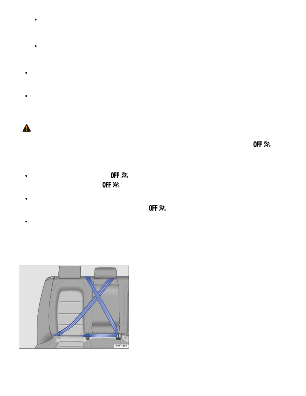
If a seat heater has been retrofitted or otherwise added to the front passenger seat,
never install any child restraint system on this seat.
Make sure that there are no wet objects (such as a wet towel) and no water or other liq‐
uids on the front passenger seat cushion.
Always buckle the child restraint firmly in place even if a child is not sitting in it. A loose child
restraint can fly around during a sudden stop or in a collision.
Always read and heed all WARNINGS whenever using a child restraint in a vehicle. See
⇒Safety belts , ⇒Airbag system , and ⇒Child safety and child restraints .
WARNING
To reduce the risk of serious injury, always make sure that the PASSENGERAIRBAG
light comes on and stays on whenever a child restraint is installed on the front passenger seat
and the ignition is switched on.
If the PASSENGERAIRBAG light does not stay on, perform the checks described
⇒PASSENGERAIRBAG light .
Take the child restraint off the front passenger seat and install it properly at one of the rear
seat positions if the PASSENGERAIRBAG light does not stay on.
Have the airbag system inspected immediately by an authorized Volkswagen dealer or autho‐
rized Volkswagen Service Facility.
Using a child restraint on the rear seat
Fig.37Keep unused safety belts away from children in child restraints.
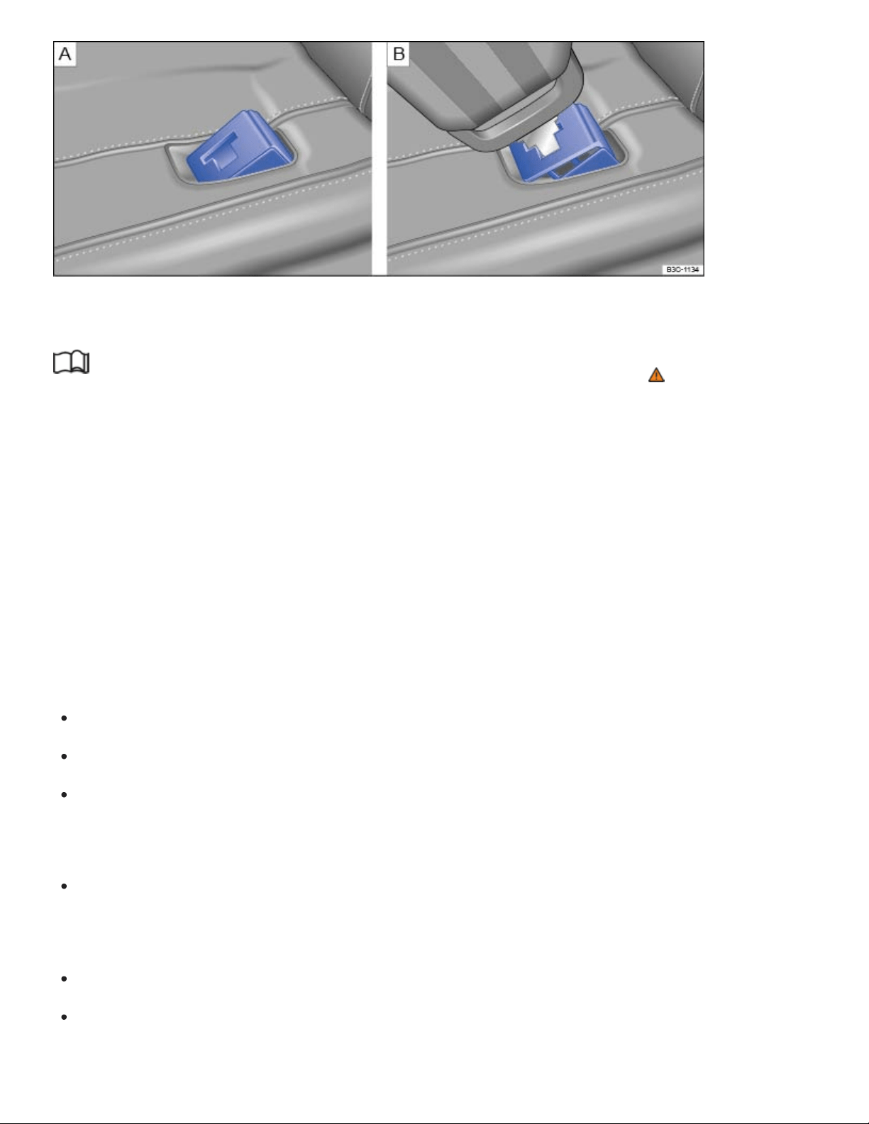
Fig.38 Protective cover for the safety belt buckle. Removal of protective cover with the safety belt
tongue.
Read and follow the introductory information and safety information first⇒ Introduction to the
subject
Important special steps when installing a child restraint with LATCH/UAS lower universal anchor‐
ages or with the vehicle safety belt.
You must take special precautions to prevent a child from playing with an unused safety belt and be‐
coming entangled with it ⇒Fig.37 . Always route the center safety belt and the unused safety belt for
the seating position where the child restraint is being installed securely out of the child’s reach.
Securing the unused safety belts out of the child's reach
Secure an unused safety belt to help prevent a child from playing with and becoming entangled in the
safety belt. The method for securing an unused safety belt depends on the seating position.
Route the safety belt around the head restraint for the center seating position ⇒Fig.37 .
Make sure the safety belt is out of the child’s reach, so that the child cannot grab and play with it.
Make sure that the safety belt does not block the LATCH/UAS lower universal anchorages. This
could prevent you from correctly installing a child restraint with the LATCH/UAS lower universal
anchorages.
Do not activate the switchable locking feature. Otherwise it will be very difficult to wind the safety
belt back into its normal position. You should not hear a clicking sound when the safety belt
retracts.
Buckle the safety belt ⇒Fig.37 .
Pull the shoulder belt portion of the safety belt all the way out of the retractor to activate the
switchable locking feature. You should hear a clicking noise as the belt winds back into the

retractor.
Let the safety belt fully retract and then pull on it to make sure the switchable locking feature is ac‐
tive and the safety belt is properly fastened and tight so that the child cannot grab and play with
the safety belt.
When a child is secured on the second or third rows, adjust the position in front of the child restraint
to provide the child with sufficient space. For example, adjust the front passenger seat to the size of
the child and the child directly behind it. Consider the proper seating position of the passenger ⇒ .
When child restraints are not needed, be sure to remove the safety belt(s) from around the head
restraint(s), unbuckle the center safety belt, and return all safety belts to their normal stored positions
so that they will be available for regular use.
How to tell if the child restraint is properly installed
The child restraint is flush with both the seat cushion and the seat backrest, unless a small gap
between the child restraint and the seat backrest is allowed by the child restraint manufacturer.
The child restraint does not hang over the edge of the vehicle seat by more than what is allowed
by the child restraint manufacturer.
The child restraint is centered in the seating position and is not installed at an angle.
The child restraint does not move forward or sideways by more than about 1 inch (2.5 cm).
The child restraint does not contact or push against any of the safety belt buckles, because this
can cause damage to the buckles and make the buckles unusable or unsafe.
The child restraints do not interfere with each other and each stays fully functional and accessible
to properly restrain and protect each child.
The child restraint is installed with LATCH/UAS or the vehicle safety belt according to the weight
limits stated on the child restraint and that the child restraint’s top tether is used as instructed by
the child restraint manufacturer.
Protecting the safety belt buckles from damage
A child restraint in the center seating position may damage the safety belt buckles on either side of
the child restraint and make them unusable or unsafe. You can help to prevent damage to the safety
belt buckles as follows:
Install the child restraint properly ⇒How to tell if the child restraint is properly installed .
Only install a child restraint that fits between the safety belt buckles in the center seating position.

Check regularly that the child restraint has not shifted and come into contact with any of the safety
belt buckles.
Check regularly that the safety belt buckles have not been damaged in any way.
As additional help in preventing damage to the safety belt buckles, a protective cover for the safety
belt buckles will be available from an authorized Volkswagen dealer or authorized Volkswagen
Service Facility. Whenever a child restraint will be installed on the center seating position either with
LATCH/UAS lower universal anchorages or with the vehicle safety belt, a protective cover should be
attached to any safety belt buckles that may come in contact with the installed child restraint.
Attach the protective cover to any unused safety belt buckles which might come in contact with
the child restraint before installing a child restraint on the center seating position.
Place the protective cover on top of the safety belt buckle, and push it in until you hear it latch
securely.
Pull on the protective cover to make sure that it is securely latched in the buckle.
Insert the safety belt tongue into the slit in the protective cover and press the buckle release but‐
ton below ⇒Fig.38 . The protective cover is ejected.
When a protective cover is attached to a safety belt buckle, that buckle cannot be used with the
safety belt. Remove the protective cover before allowing someone to use that seating position.
WARNING
A child in a child restraint installed with the LATCH/UAS lower universal anchorages or with the
standard safety belt on the rear seat may play with unused rear seat safety belts and become en‐
tangled, resulting in serious personal injury and even death.
Always secure unused rear seat safety belts out of the reach of children in child restraints such
as by properly routing them around the head restraint adjacent to the seating position where
the child restraint is installed.
NOTE
The outboard safety belts may become damaged if they are secured improperly.
Be careful not to activate the switchable locking retractor when routing the unused safety belt
around the head restraint. Otherwise it will be very difficult to wind the safety belt back into its
normal position.
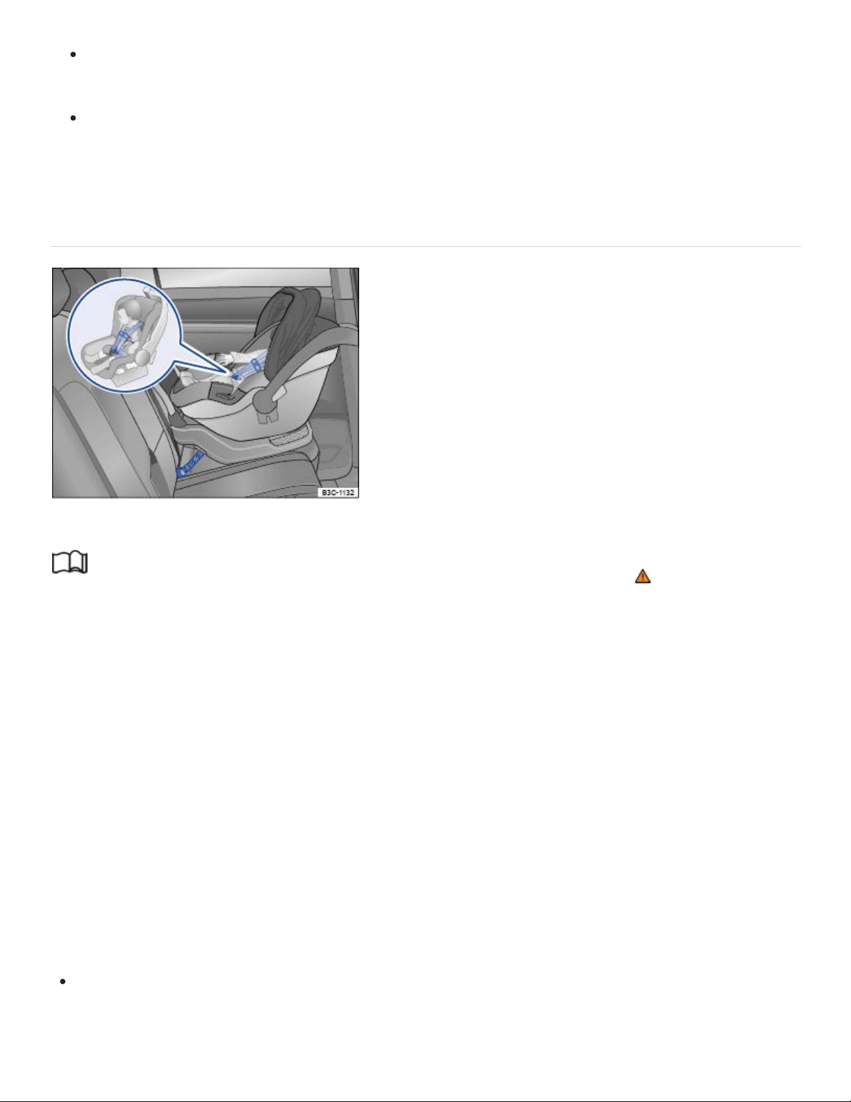
Only pull the unused safety belt out far enough to allow you to route the belt around the head
restraint. If the safety belt is pulled out too far, the switchable locking feature will be activated.
When installing a child restraint, be careful not to get the belt caught in the structure of the
child restraint and become damaged, especially when the switchable locking feature has been
activated.
Infant seats
Fig.39Example of a rearward-facing infant seat properly installed on the rear seat.
Read and follow the introductory information and safety information first⇒ Introduction to the
subject
The American Academy of Pediatrics (AAP) recommends that all infants should ride in rear-facing car
child restraints (in which the child faces the back of the vehicle) starting with their first ride home from
the hospital. All infants and toddlers (generally up to age3) should ride in a rear-facing car child re‐
straint as long as possible – or until they reach the highest weight or height allowed by their child
restraint’s manufacturer. These infant seats support the baby's back, neck and head in a collision.
Rear-facing child restraints can be used safely only on the rear seats of the vehicle ⇒Fig.39 . The
best place for a rear-facing child restraint is in the second row where the child restraint can be in‐
stalled with the LATCH/UAS system.
Before installing a child restraint on the front passenger seat, be sure to follow the special instructions
and heed the warnings ⇒Child restraints and the Advanced Airbag System and ⇒The dangers of
using child restraints on the front seat .
When using the vehicle safety belt to install a child restraint (except a booster seat), you must ac‐
tivate the switchable locking feature on the safety belt to help prevent the child restraint from mov‐

ing ⇒Using a child restraint on the rear seat . Always follow the child restraint manufacturer’s in‐
structions when installing a child restraint.
Attach the Top Tether strap or straps to the tether anchorage for the seating position where the
child restraint is being installed with either the LATCH/UAS system or with a safety belt
⇒Securing a child restraint with the Top Tether strap .
Follow the manufacturer's instructions for positioning the handle of the car seat when it is installed
in the vehicle.
The airbag on the passenger side makes the front seat a potentially dangerous place for a child to
ride. The front seat is not the safest place for a child in a forward-facing child restraint. It is a very
dangerous place for an infant or a larger child in a rearward-facing seat.
You must take special precautions when installing a child restraint with the vehicle safety belt or with
LATCH/UAS lower universal anchorages on a rear seating position. Always route the center safety
belt and the unused safety belt for the seating position where the child restraint is being installed se‐
curely out of the child’s reach. Securing the safety belts will help prevent a child from playing with an
unused safety belt and becoming entangled with it ⇒Using a child restraint on the rear seat ,
⇒Fig.37 .
DANGER!
Not using a child restraint, using the wrong child restraint or improperly installing a child restraint
increases the risk of serious personal injury and death in a collision or other emergency situation.
Never install rearward-facing child restraints or infant carriers on the front passenger seat,
even with an Advanced Airbag System. A child will be seriously injured and can be killed when
the inflating airbag hits the child restraint or infant carrier with great force and smashes the
child restraint and child against the backrest, center armrest, door or roof.
Always install rearward-facing child restraints and infant carriers on the rear seats.
Never install a rearward-facing child restraint in the forward-facing direction. These restraints
are designed for the special needs of infants and very small children and cannot protect them
properly if the seat is forward-facing.
If you must install a rearward facing child restraint on the front passenger seat because of ex‐
ceptional circumstances, but the PASSENGERAIRBAG light does not come on and
stay on, immediately install the rearward-facing child restraint at a seating position on the rear
rows and have the airbag system inspected right away by your authorized Volkswagen dealer
or authorized Volkswagen Service Facility.
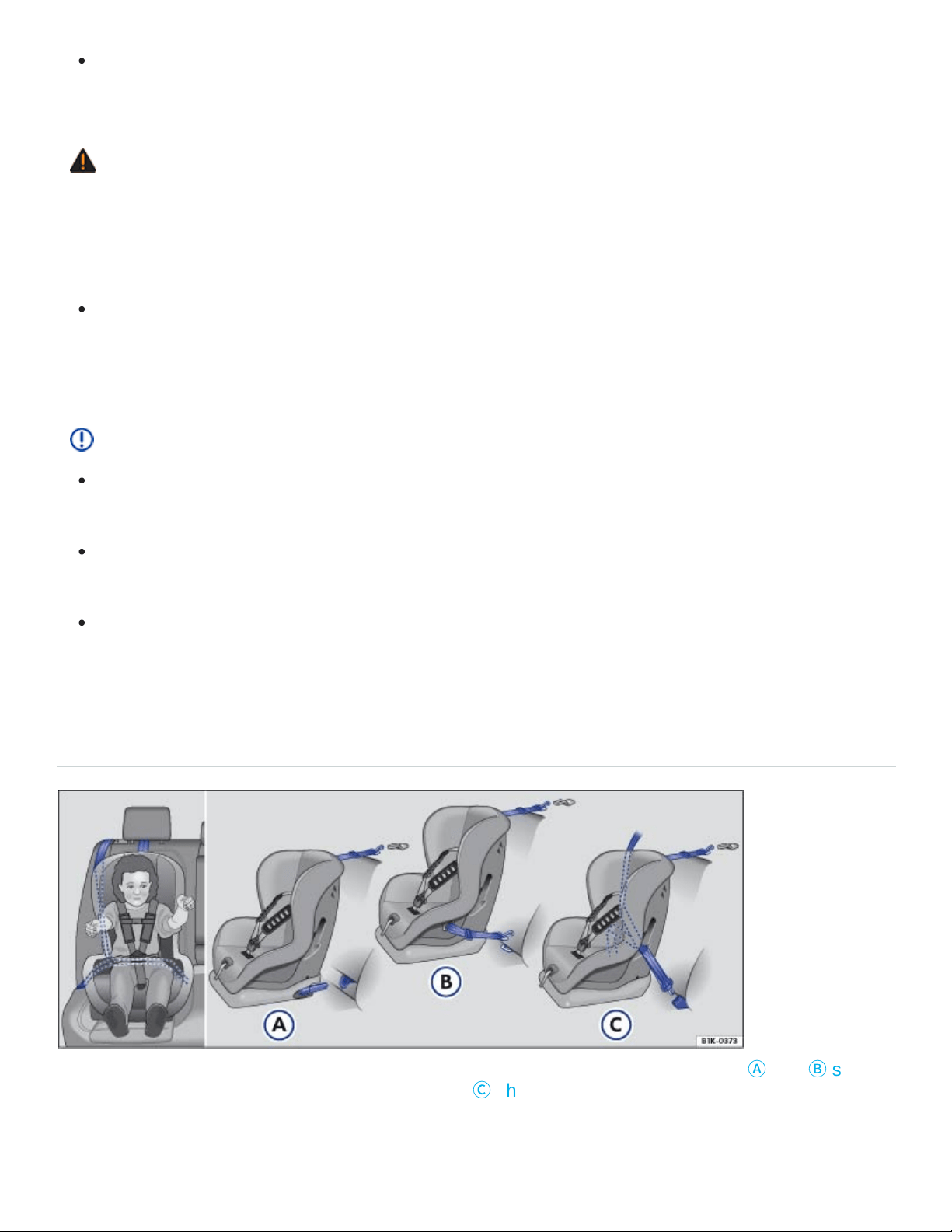
Always read and heed all WARNINGS whenever using a child restraint in a vehicle. See
⇒Safety belts , ⇒Airbag system , and ⇒Child safety and child restraints .
WARNING
A child in a child restraint installed with the LATCH/UAS lower universal anchorages or with the
standard safety belt on the rear seat may play with unused rear seat safety belts and become en‐
tangled, resulting in serious personal injury and even death.
Always secure unused rear seat safety belts out of the reach of children in child restraints such
as by properly routing them around the head restraint adjacent to the seating position where
the child restraint is installed.
NOTE
Be careful not to activate the switchable locking retractor when routing the unused safety belt
around the head restraint adjacent to the seat where a child restraint has been installed.
Only pull the unused safety belt out far enough to allow you to route the belt around the head
restraint.
When installing a child restraint with a safety belt, be careful not to get the belt caught in the
structure of the child restraint and become damaged, especially when the switchable locking
feature has been activated.
Convertible child restraints
Fig.40All convertible child restraints have lower anchors and a Top Tether. Figures
Ⓐ
and
Ⓑ
show
how to correctly install a LATCH/UAS seat. Figure
Ⓒ
shows the set up of a seat using the vehicle's
safety belt system.

Read and follow the introductory information and safety information first⇒ Introduction to the
subject
Children between 1and about 7years old must always be properly restrained in a child restraint certi‐
fied for their size and weight ⇒Fig.40 .
Once your child outgrows the rear-facing car seat (generally up to age3), your child is ready to travel
in a forward-facing car seat with a harness. Keep your child in a forward-facing car seat with a har‐
ness until he or she reaches the top height or weight limit allowed by your car seat’s manufacturer.
Before installing a child restraint on the front passenger seat, be sure to follow the special instructions
and heed the warnings ⇒Child restraints and the Advanced Airbag System and ⇒The dangers of
using child restraints on the front seat .
When using the vehicle safety belt to install a child restraint, you must activate the switchable
locking feature on the safety belt to help prevent the child restraint from moving ⇒Using a child
restraint on the rear seat .
Push the child restraint down with your full weight to get the safety belt really tight so that the seat
cannot move forward or sideways more than about 1inch (2.5cm).
Make sure that the child restraint is centered in the seating position and is not installed at an
angle.
The child restraint must not contact or push against any of the safety belt buckles, because this
can cause damage to the buckles and make the buckles unusable or unsafe.
Fasten the harness webbing that is part of the child restraint system securely and pull it tight so
that you can only slip one finger underneath the shoulder belt portion at the child's chest.
Attach the Top Tether strap to the tether anchorage for the seating position where the child re‐
straint is being installed with either the LATCH/UAS system or the safety belt ⇒Securing a child
restraint with the Top Tether strap .
The airbag on the passenger side makes the front seat a potentially dangerous place for a child to
ride. The front seat is not the safest place for a child in a forward-facing child restraint. It is a very
dangerous place for an infant or a larger child in a rearward-facing seat.
You must take special precautions when installing a child restraint with the vehicle safety belt or with
LATCH/UAS lower universal anchorages on the rear seating positions. Always route the center safety
belt and the unused safety belt for the seating position where the child restraint is being installed se‐

curely out of the child’s reach. Securing the safety belts will help prevent a child from playing with an
unused safety belt and becoming entangled with it ⇒Using a child restraint on the rear seat ,
⇒Fig.37 .
DANGER!
Not using a child restraint, using the wrong child restraint or improperly installing a child restraint
increases the risk of serious personal injury and death in a collision or other emergency situation.
Children on the front seat of any car, even with Advanced Airbags, can be seriously injured or
even killed when an airbag inflates.
A child in a rearward-facing child restraint installed on the front passenger seat will be seri‐
ously injured and can be killed if the front airbag inflates – even with an Advanced Airbag
System.
The inflating airbag will hit the child restraint or infant carrier with great force and will smash
the child restraint and child against the backrest, center armrest, door or roof.
Always install rearward-facing child restraints on the rear seat.
If you must install a rearward facing child restraint on the front passenger seat because of ex‐
ceptional circumstances, but the PASSENGERAIRBAG light does not come on and
stay on, immediately install the rearward-facing child restraint at a seating position on the rear
seat and have the airbag system inspected right away by your authorized Volkswagen dealer
or authorized Volkswagen Service Facility.
Always read and heed all WARNINGS whenever using a child restraint in a vehicle. See
,ChapterSafety belts, ,ChapterAirbag system, and ⇒Child safety and child restraints .
WARNING
An improperly installed child restraint can interfere with the airbag as it deploys and seriously in‐
jure or even kill the child – even with an Advanced Airbag System.
If exceptional circumstances require the use of a forward-facing child restraint on the front
passenger's seat, the child's safety and well-being require the following special precautions to
be taken:
Forward-facing child restraints installed on the front passenger seat may interfere with
the deployment of the airbag and cause serious personal injury to the child.

Always make sure that the forward-facing seat has been designed and certified by its
manufacturer for use on a front passenger seat with a front and side airbag.
Always carefully follow the manufacturer's instructions provided with the child restraint or
carrier.
Never install a child restraint without a properly attached top tether strap if the child re‐
straint manufacturer's instructions require the top tether strap for proper installation, or if
required by law. For example, the use of a top tether strap for forward-facing child re‐
straints is required by law in Canada.
Never put the forward-facing child restraint up against or very near the instrument panel.
Always set the safety belt upper anchorage to the adjustment position that permits
proper installation in accordance with the child restraint manufacturer's instructions.
Always move the front passenger seat to the highest position in the up and down adjust‐
ment range and move it back to the rearmost position in the seat's fore and aft adjust‐
ment range, as far away from the airbag as possible before installing the forward-facing
child restraint.
Always make sure that the safety belt upper anchorage is behind the child restraint and
not next to or in front of the child restraint so that the safety belt will be properly
positioned.
Always make sure that nothing is in the way that prevents the front passenger's seat
from being moved to the rearmost position in its fore and aft adjustment range.
Always make sure that the backrest is in the upright position.
Never place objects on the seat (such as a laptop, CD player, or electronic games de‐
vice). These may influence the electrical capacitance measured by the capacitive pas‐
senger detection system and can also fly around in an accident and cause serious per‐
sonal injury.
If a seat heater has been retrofitted or otherwise added to the front passenger seat,
never install any child restraint system on this seat.
Make sure that there are no wet objects (such as a wet towel) and no water or other liq‐
uids on the front passenger seat cushion.

Make sure that the PASSENGERAIRBAG light comes on and stays on all the
time whenever the ignition is switched on.
If the PASSENGERAIRBAG light does not come on and stay on, immediately in‐
stall the forward-facing child restraint at a seating position on the rear seat and have the
airbag system inspected by your authorized Volkswagen dealer or authorized
Volkswagen Service Facility.
Always buckle the child restraint firmly in place even if a child is not sitting in it. A loose child
restraint can fly around during a sudden stop or in a collision.
WARNING
A child in a child restraint installed with the LATCH/UAS lower universal anchorages or with the
standard safety belt on the rear seat may play with unused rear seat safety belts and become en‐
tangled, resulting in serious personal injury and even death.
Always secure unused rear seat safety belts out of the reach of children in child restraints such
as by properly routing them around the head restraint adjacent to the seating position where
the child restraint is installed.
NOTE
Be careful not to activate the switchable locking retractor when routing the unused safety belt
around the head restraint adjacent to the seat where a child restraint has been installed.
Only pull the unused safety belt out far enough to allow you to route the belt around the head
restraint.
When installing a child restraint with a safety belt, be careful not to get the belt caught in the
structure of the child restraint and become damaged, especially when the switchable locking
feature has been activated.
Booster seats and safety belts

Fig.41Child properly restrained in a booster seat in the second row.
Fig.42Child properly restrained in a booster seat in the third row.
Read and follow the introductory information and safety information first⇒ Introduction to the
subject
Children between about 8to 12years old are best protected in child restraints designed for their age
and weight. Experts say that the skeletal structure, particularly the pelvis, of these children is not fully
developed, and they must not use the vehicle safety belts without a suitable child restraint.
The vehicle's safety belts alone will not fit most children until they are at least 4ft. 9in. (57inches /
1.45meters) tall. Booster seats raise these children up so that the safety belt will pass properly over
the strong parts of their bodies and the safety belt can help protect them in a collision.
Do not use the switchable locking feature when using the vehicle's safety belt to restrain a child on
a booster seat.
Always position the shoulder portion of the safety belt midway over the child's shoulder. If you
must transport an older child in a booster seat on the front passenger seat, you can use the safety
belt height adjustment to help adjust the shoulder portion properly.

Always make sure that the shoulder portion is snug across the shoulder and chest and never rests
against or across the child's neck or face.
Always make sure that the child can wear the lap belt portion across the upper thighs and never
over the stomach or abdomen.
Children who are at least 4ft. 9in. (57inches / 1.45meters) tall can generally use the vehicle's
3point lap and shoulder belts. Never use the lap belt portion of the vehicle's safety belt alone to re‐
strain any child, regardless of how big the child is. Always remember that children do not have the
pronounced pelvic structure required for the proper function of lap belt portion of the vehicle's 3point
lap and shoulder belts. The child's safety absolutely requires that a lap belt portion of the safety belt
be fastened snugly across the upper thighs. Never let the lap belt portion of the safety belt pass over
the child's stomach or abdomen.
It is usually best to put these children in appropriate booster seats and keep them in a booster seat
until they are big enough to fit in a safety belt properly. Be sure the booster seat meets all applicable
safety standards.
Booster seats raise the seating position of the child and reposition both the lap and shoulder parts of
the safety belt so that they pass across the child's body in the right places. The routing of the belt
over the child's body is very important for the child's protection, whether or not a booster seat is used.
Children age12 and under must always ride in the rear seat.
Keep your child in a booster seat until he or she is at least 4ft.9in. (57inches / 1.45meters) tall AND
your child is:
tall enough to sit without slouching; and
able to keep his or her back against the vehicle seat; and
able to keep his or her knees naturally bent over the edge of the vehicle seat; and
able to keep his or her feet flat on the floor; and
able to sit in that position during the entire trip.
The way the safety belt passes over the child’s body is important for their safety and protection in a
crash. Always make sure you child can wear the safety belt properly:
The lap belt must lie snugly across the upper thighs, not the stomach.
The shoulder belt must lie snugly across the shoulder and chest, and never cross the neck or
face.

Never let a child put the shoulder belt under the arm or behind the back, because it could cause
severe injuries in a crash.
Always check belt fit on the child in every vehicle. A booster seat may be needed in some vehicles
and not in others. If the safety belt does not fit properly, the child must continue to use a booster seat.
Regardless of whether the child is using a booster or is able to properly wear the standard safety belt
properly without a booster seat, keep your child in the back seat. Accident statistics show that chil‐
dren are safer on the rear seat than on the front seat.
In a collision, airbags must inflate within a blink of an eye and with considerable force. In order to do
its job, the airbag needs room to inflate so that it will be there to protect the occupant as the occupant
moves forward into the airbag.
Even Advanced Airbags can injure children when they inflate. A vehicle occupant who is out of posi‐
tion and too close to the airbag gets in the way of an inflating airbag. When an occupant is too close,
he or she will be struck violently and will receive serious or possibly even fatal injuries.
In order for the airbag to offer protection, it is important that all vehicle occupants, especially children,
who must be in the front seat under exceptional circumstances, be properly restrained and as far
away from the airbag as possible. By keeping room between the child's body and the front of the pas‐
senger compartment, the airbag can inflate completely and provide supplemental protection in certain
frontal collisions.
You must take special precautions when installing a booster seat with the vehicle safety belt on the
rear seats. Always route and secure the unused center safety belt to help prevent a child from playing
with the unused safety belt and becoming entangled in it ⇒Using a child restraint on the rear seat ,
⇒Fig.37 .
WARNING
Not using a booster seat, using the booster seat improperly, incorrectly installing a booster seat
or using the vehicle safety belt improperly increases the risk of serious personal injury and death
in a collision or other emergency situation. To help reduce the risk of serious personal injury
and/or death:
Never use the switchable locking feature when using the vehicle's safety belt to restrain a child
on a booster seat.
Always make sure to position the shoulder portion of the 3point belt over the middle of the
child's shoulder.

Never let the shoulder portion of the safety belt rest against or across the neck, face, chin, or
throat of the child.
Always make sure the lap belt portion of the 3point belt is worn snugly across the upper
thighs. Never let the lap belt portion of the safety belt pass over the child's stomach or
abdomen.
Never let a child put the shoulder belt under the arm or behind the back, because it could
cause severe injuries in a crash.
Failure to properly route safety belts over a child's body will cause severe injuries in a collision
or other emergency situation.
Children on the front seat of any car, even with Advanced Airbags, can be seriously injured or
even killed when an airbag inflates.
Never let a child stand or kneel on any seat, for example, the front seat.
Never let a child ride in the cargo area of your vehicle.
Always remember that a child leaning forward, sitting sideways or out of position in any way
during a collision can be struck by a deploying airbag. This will result in serious personal injury
or death.
If you must install a booster seat on the front passenger seat because of exceptional circum‐
stances, the PASSENGERAIRBAG light must come on and stay on, whenever the ig‐
nition is switched on.
If the PASSENGERAIRBAG light does not come on and stay on, perform the checks
described ⇒PASSENGERAIRBAG light .
Take the child restraint off the front passenger seat and install it properly at one of the seating
positions on the rear rows if the PASSENGERAIRBAG light does not stay on when‐
ever the ignition is switched on.
Always read and heed all WARNINGS whenever using a child restraint in a vehicle. See
⇒Safety belts , ⇒Airbag system , and ⇒Child safety and child restraints .
WARNING
A child in a child restraint installed with the LATCH/UAS lower universal anchorages or with the
standard safety belt on the rear seats may play with unused rear seat safety belts and become
entangled, resulting in serious personal injury and even death.

Always secure unused rear seats safety belts out of the reach of children in child restraints
such as by properly routing them around the head restraint adjacent to the seating position
where the child restraint is installed.
Installing child restraints with a safety belt
Read and follow the introductory information and safety information first⇒ Introduction to the
subject
Safety belts for the rear seats and the front passenger seat must be locked with the switchable lock‐
ing feature to properly secure child restraints.
Child restraints are designed to be secured to the vehicle either with the 3point lap and shoulder belt
or with LATCH/UAS lower universal anchorages. The child restraint may also have a Top Tether strap,
which must be used if required by the child restraint manufacturer or by law ⇒Securing a child re‐
straint with the Top Tether strap .
Regardless of the kind of child restraint that you use, always make sure that the child restraint is
properly secured in the vehicle; otherwise the child could be seriously injured in a crash. Always fol‐
low legal requirements regarding the installation of child restraints.
Place the child restraint on a seat, preferably on a rear seat⇒ .
Switchable locking feature
Whenever a child restraint (except a booster seat) is installed with a safety belt, the safety belt must
be locked so that the safety belt webbing cannot unreel ⇒Activating the switchable locking feature .
The switchable locking feature lets you lock the belt so that a child restraint can be properly installed
and, for example, so that it cannot tip to the side when the vehicle goes around a corner.
Installing the child restraint on a rear seat
Always carefully follow the child restraint manufacturer's instructions when installing a child restraint
in your vehicle ⇒ .
Make sure that the child restraint is centered in the seating position and is not installed at an
angle.
Make sure that the child restraint does not contact or push up against any safety belt buckles, be‐
cause this can cause damage to the buckles and make the buckles unusable or unsafe.

Always make sure the child restraint does not hang over the edge of the vehicle seat by more
than the generally accepted 20% of the child restraint. Always follow the overhang limits allowed
by the child restraint manufacturer.
Route the safety belt around or through the child restraint using the proper path for the safety belt
as specified by the child restraint manufacturer.
Insert the belt tongue into the buckle for that seating position.
Make sure that the red release button faces away from the child restraint so that it can be unbuck‐
led quickly.
Remove all slack from the lap belt portion of the safety belt and hold it tightly against the child
restraint.
Push the child restraint down with your full weight to make sure that the child restraint will be prop‐
erly installed with the safety belt really tight.
Activate the belt's switchable locking feature ⇒Activating the switchable locking feature .
Pull on the safety belt to make sure the safety belt is properly fastened and tight.
Check the child restraint for proper installation by pulling on the child restraint at the place where
the vehicle's safety belt goes into the child restraint. The child restraint should not move forward or
sideways by more than about 1inch (2.5cm).
Special instructions for installing child restraints if the child restraint must be installed on the front
seat
Always carefully follow the child restraint manufacturer's instructions when installing a child restraint
in your vehicle ⇒ .
Place the child restraint on a seat, preferably on a rear seat⇒ . If in exceptional circum‐
stances you must install the child restraint on the front seat, be sure to follow the special instructions
and heed the WARNINGS below.
Make sure the front seat backrest is in the upright position.
Move the front passenger seat to the rearmost position in the seat's fore and aft adjustment range,
as far away from the airbag as possible.
Set the front passenger's safety belt height adjuster so that available safety belt length is sufficient
to properly install the child restraint.
Always make sure that the safety belt upper anchorage is behind the child restraint and not next
to or in front of the child restraint so that the safety belt will be properly positioned.

Route the safety belt around or through the child restraint using the proper path for the safety belt
as specified by the child restraint manufacturer.
Insert the belt tongue into the buckle for that seating position.
Make sure that the red release button faces away from the child restraint so that it can be unbuck‐
led quickly.
Remove all slack from the lap belt portion of the safety belt and hold it tightly against the child
restraint.
Push the child restraint down with your full weight to make sure that the child restraint will be prop‐
erly installed with the safety belt really tight.
Activate the belt's switchable locking feature ⇒Activating the switchable locking feature .
Pull on the safety belt to make sure the safety belt is properly fastened and tight.
Check the child restraint for proper installation by pulling on the child restraint at the place where
the vehicle's safety belt goes into the child restraint. The child restraint should not move forward or
sideways by more than about 1inch (2.5cm).
Make sure that the child restraint is centered on the seat and is not installed at an angle.
After checking to make sure that the child restraint is properly installed, make certain that the child
restraint is correctly recognized by the capacitive passenger detection system in the front passen‐
ger seat and that the PASSENGERAIRBAG light signals the correct front passenger front
airbag status. Please be sure to read the additional important information and heed the
WARNINGS about the Advanced Airbag System and the function of the PASSENGERAIRBAG
light in this Manual.
Always remember: Even though your vehicle is equipped with an Advanced Airbag System, all chil‐
dren, especially those 12years and younger, must always ride in the back seat properly restrained for
their age and size.
Activating the switchable locking feature
Slowly pull the shoulder belt portion of the safety belt all the way out of the retractor.
While keeping your weight on the child restraint, guide the shoulder belt portion of the safety belt
back into the retractor until the belt lies flat and is tightened against the child restraint.
You should hear a clicking noise as the belt winds back into the inertia reel of the safety belt re‐
tractor. Test the switchable locking feature by pulling on the belt. You should no longer be able to
pull the belt out of the retractor. The switchable locking feature is now active.

Deactivating the switchable locking feature
The switchable locking feature for child restraints will be deactivated automatically when the belt is
wound all the way back into the retractor.
Press the red button on the safety belt buckle. The belt tongue will pop out of the buckle.
Guide the safety belt back by hand so that it rolls easily onto the retractor and the trim around the
retractor will not be damaged.
Always let the safety belt retract completely into its stowed position. The safety belt can now be used
as an ordinary safety belt without the switchable locking feature for child restraints.
If the switchable locking feature should be activated inadvertently, the safety belt must be unfastened
and guided completely back into its stowed position to deactivate this feature. If the switchable lock‐
ing feature is not deactivated, the safety belt will gradually become tighter and uncomfortable to wear.
WARNING
Using the wrong child restraint or an improperly installed child restraint can cause serious per‐
sonal injury or death in an accident.
Always make sure that the safety belt retractor is locked when installing a child restraint, ex‐
cept a booster seat. An unlocked safety belt retractor cannot hold the child restraint in place
during normal driving or in a crash.
Always buckle the child restraint firmly in place even if a child is not sitting in it. A loose child
restraint can fly around during a sudden stop or in a collision.
Always make sure the seat backrest to which the child restraint is installed is in an upright po‐
sition and securely latched into place and cannot fold forward. Otherwise, the seat backrest
with the child restraint attached to it could fly forward in a collision or other emergency
situation.
Always read and heed all WARNINGS whenever using a child restraint in a vehicle ⇒Child
safety and child restraints . Special precautions apply when installing a child restraint on the
front passenger seat ⇒The dangers of using child restraints on the front seat , and ⇒Child re‐
straints and the Advanced Airbag System , and ⇒Important safety instructions for using child
restraints .
WARNING
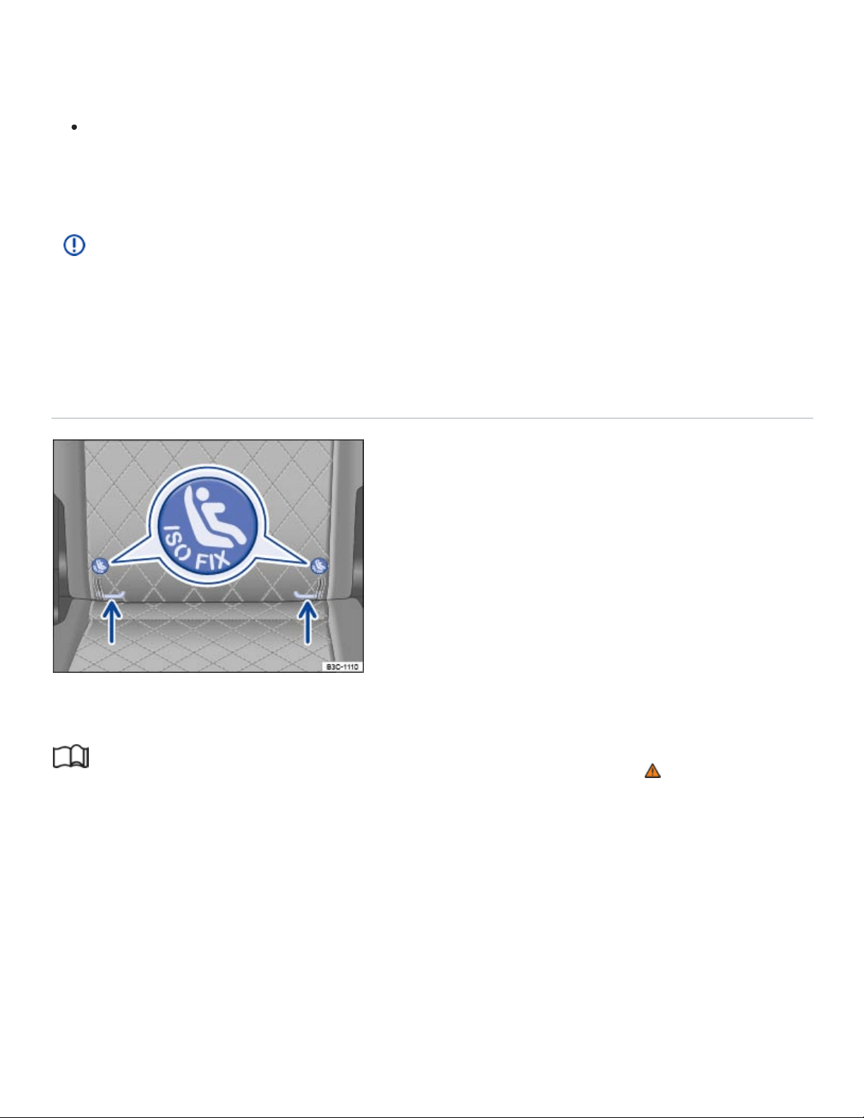
Improperly installed child restraints increase the risk of serious personal injury and death in a
collision.
Never unfasten the safety belt to deactivate the switchable locking feature for child restraints
while the vehicle is moving. You would not be restrained and could be seriously injured in an
accident.
NOTE
When installing a child restraint, be careful not to get the belt caught in the structure of the child
restraint and become damaged, especially when the switchable locking feature has been
activated.
Securing the child restraint with LATCH/UAS lower universal anchorages
Fig.43On the second row seat backrests: Markings indicating the location of the LATCH/UAS lower
universal anchorages.
Read and follow the introductory information and safety information first⇒ Introduction to the
subject
LATCH is used in the United States and stands for Lower Anchors and Tethers for Children. In
Canada, UAS (Universal Anchorage System) is used to describe the combination of top tether straps
and lower anchorages.
All child restraints manufactured after September1,1999 must have LATCH/UAS lower universal
anchorages.

Each seating position in the second row has the LATCH/UAS lower universal anchorage attachment
points on the lower part of the backrests. The circular markings on the backrests help you to locate
the lower anchorages ⇒Fig.43 . The third row seating positions do not have LATCH/UAS lower uni‐
versal anchorage attachment points.
LATCH/UAS lower universal anchorages secure the child restraint system in the seat without using
the vehicle's safety belts. Anchorages provide a secure and easy-to-use attachment and minimize the
possibility of improper child restraint installation.
Remember that the LATCH/UAS lower universal anchorage points are only intended for installation
and attachment of child restraints specifically certified for use with these lower universal anchorages.
Child restraints that are not equipped with the LATCH/UAS lower universal anchorage attachments
can still be installed with vehicle safety belts according to the child restraint manufacturer's instruc‐
tions. You must never mount twochild restraint systems to one LATCH/UAS lower universal anchor‐
age point at the same time. For example, never install a child restraint with LATCH/UAS lower univer‐
sal anchorage points on one of the second row outboard seating positions and then use the inboard
anchorage to also install a child restraint in the center of the second row. Instead, use the
LATCH/UAS lower universal anchorage points specifically intended for the second row center seat.
The child restraint must not contact or push against any of the safety belt buckles to help prevent
damage to the buckles, which can make the buckles unusable or unsafe.
There are 2ways to attach an appropriate child restraint to the LATCH/UAS lower universal
anchorages:
Rigid connectors on bars at the back of the child restraint:
Depending on your vehicle's seats, you may want to use guide fixtures when installing a child re‐
straint that has rigid mountings. Installation with guide fixtures is easier and protects the upholstery.
Guide fixtures are included with the child restraint in some cases. If not, they can be purchased from
an authorized Volkswagen dealer or an authorized Volkswagen Service Facility. The guide fixtures
must be installed in accordance with the manufacturer's instructions at the anchorage points between
the seat cushion and the seat backrest.
Make sure the seat backrest of the second row seat is in the upright position and securely latched
in place.
Release or deploy the top tether strap (if one is required by the child restraint manufacturer or by
law) to secure the seat ⇒Securing a child restraint with the Top Tether strap .

Guide the upper tether strap under the rear head restraint (raise the head restraint if necessary).
Attach the tether strap anchorage hook into the opening of the tether anchorage.
Attach the connectors onto the LATCH/UAS lower universal anchorages.
Make sure you hear the child restraint click securely into place.
Tighten the top tether strap (if there is one) to secure the seat ⇒Securing a child restraint with the
Top Tether strap .
Pull on both sides of the child restraint once you've installed it to make certain it is secure and
properly attached.
Releasing
Release the top tether strap (if one is required by the child restraint manufacturer or by law).
Release the lower latch from the LATCH/UAS lower universal anchorages following the child re‐
straint manufacturer's instructions.
Hooks attached to adjustable straps (hook-on connectors)
Make sure the seat backrest of the second row seat is in the upright position and securely latched
in place.
Attach the hook-on connectors with the spring catch release onto the LATCH/UAS lower universal
anchorage so that the connectors lock into place.
Pull on the connector attachments to make sure that it is properly attached to the LATCH/UAS
lower universal anchorage.
Pull straps tight following the child restraint manufacturer's instructions.
Release or deploy the top tether strap (if one is required by the child restraint manufacturer or by
law) to secure the seat ⇒Securing a child restraint with the Top Tether strap .
Guide the upper tether strap under the rear head restraint (raise the head restraint if necessary).
Guide the tether strap between the rear seat back and the luggage compartment cover, if
equipped.
Attach the tether strap anchorage hook into the opening of the tether anchorage and pull the top
tether strap tight.
After you have installed the child restraint, pull on both of the adjustable straps on the child re‐
straint and pull also on the tether strap to make certain the seat is secure and properly attached.

Releasing
Loosen the tension on the hook-on connector straps following the child restraint manufacturer's
instructions.
Release the top tether strap (if one is required by the child restraint manufacturer or by law).
Depress the spring catch on the hook.
Hold the spring catch in the depressed position.
Move the hook in the direction of the vehicle floor so that there is enough space to release the
connector from the lower anchorage.
You must take special precautions when installing a child restraint with the vehicle safety belt or with
LATCH/UAS lower universal anchorages on the rear seats. Always route the unused center seat
safety belt and the unused safety belt for the seating position where the LATCH/UAS child restraint is
being installed around the rear head restraint behind the child restraint to help prevent a child from
playing with the unused belt and becoming entangled in it.
WARNING
Improper use of the LATCH/UAS system can increase the risk of serious personal injury and
death in an accident.
Always carefully follow the child restraint manufacturer's instructions for proper installation of
the child restraints and proper use of tether straps as well as the LATCH/UAS lower universal
anchorages or safety belts in your vehicle.
Never mount twochild restraint systems on oneLATCH/UAS lower universal anchorage point.
These anchors were developed only for child restraints using the LATCH/UAS system.
Never attach other child restraints, belts, luggage or other things to the LATCH/UAS
anchorages.
Always make sure that you hear a click when latching the seat in place. If you do not hear a
click, the seat is not secure and could fly forward and hit the interior of the vehicle or be
ejected from the vehicle.
NOTE
A child restraint may damage the seat upholstery or the safety belt buckles if installed improperly
or left on the seat when not in use.
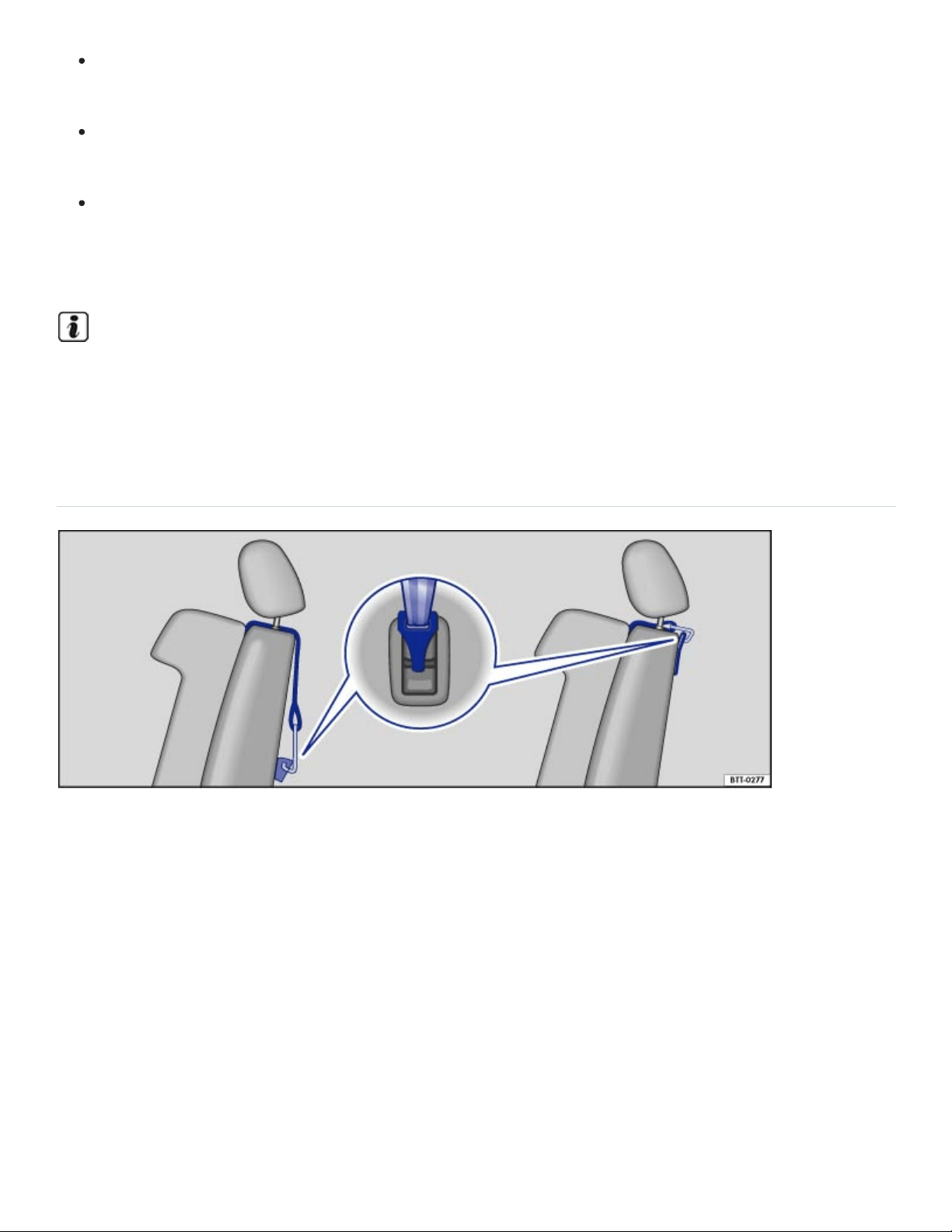
Remove the guide fixtures from the anchorage points when there is no child restraint secured
in the vehicle anchorage points.
Always remove the guide fixtures from the anchorage points before folding the backrest on the
second row seats forward.
When installing, make sure that the child restraint does not contact or push up against any
safety belt buckles, because this can cause damage to the buckles and make the buckles un‐
usable or unsafe.
Be careful not to activate the switchable locking retractor when routing the safety belts around the
head restraints. Only pull the safety belt out far enough to allow you to route the belt around the
head restraint.
Securing a child restraint with the Top Tether strap
Fig.44Example of an attached upper tether strap. The top tether strap reduces the forward move‐
ment of the child restraint in a crash. This helps to reduce the risk of head injury.
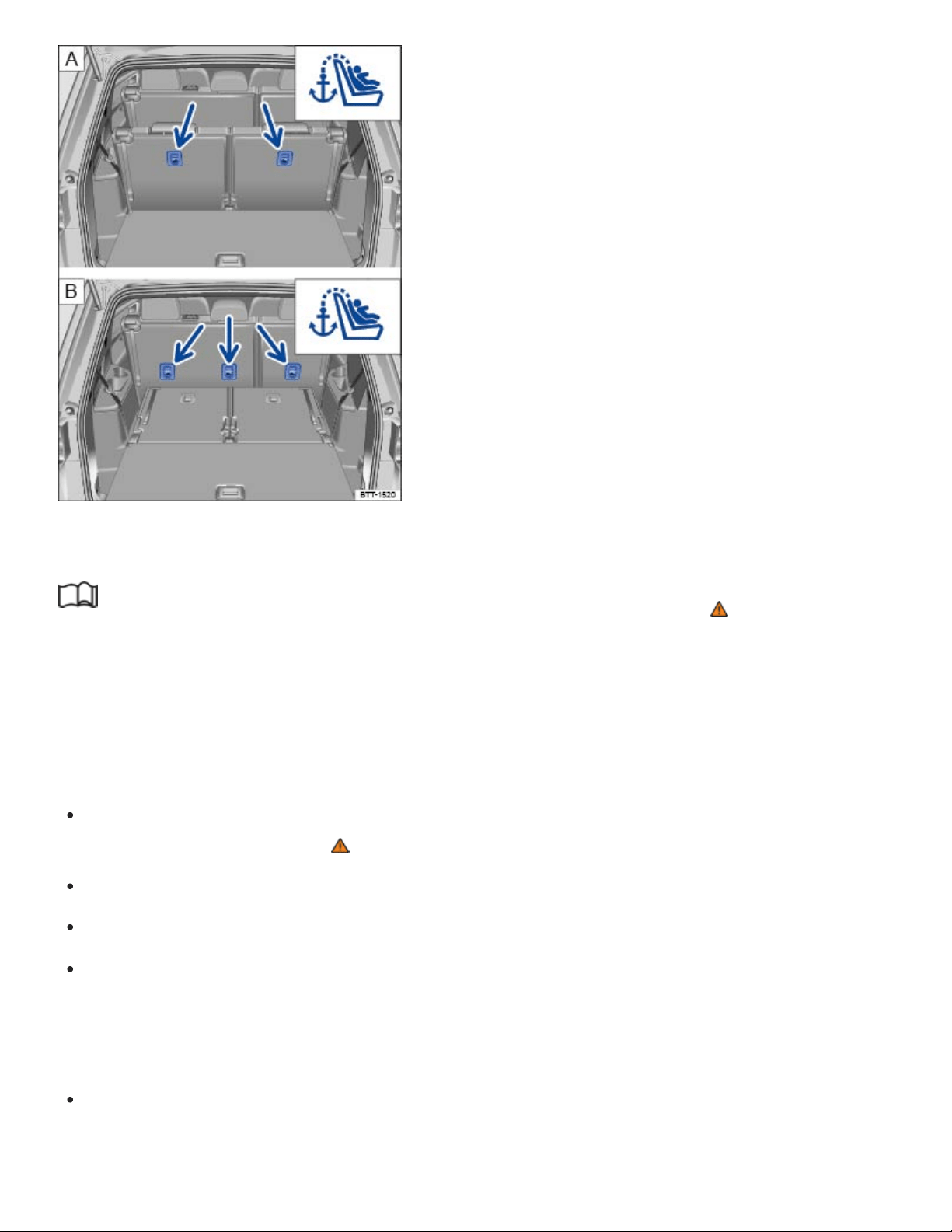
Fig.45Anchorages for the top tether strap on the back of the third row seats and the second row
seats .
Read and follow the introductory information and safety information first⇒ Introduction to the
subject
The Top Tether strap reduces the forward movement of the child restraint in a crash; this helps to re‐
duce the risk of head injury.
Installing the Top Tether strap
Release or deploy the Top Tether strap on the child restraint according to the child restraint
manufacturer's instructions ⇒ .
Remove the luggage compartment cover, if necessary.
Locate the tether anchor behind the rear seat backrest ⇒Fig.45 .
Second row outer seating positions and third row seating positions: Guide the upper tether strap
under the head restraint (raise the head restraint if necessary). For child restraints with V-tether
straps: Always make sure that the head restraint guide rods do not interfere with any part of the
top tether strap.
Second row center seating position (if applicable): Guide the upper tether strap under the center
rear head restraint only when it is pushed all the way up. If the tether strap hook is too big to pass

under the center head restraint, push the head restraint all the way down and guide the strap over
the center head restraint.
Guide the tether strap between the rear seat backrest and the luggage compartment cover, if
equipped.
Attach the tether strap anchorage hook into the opening of the tether anchorage ⇒Fig.45 .
Pull on the tether strap hook so that the spring catch of the hook is engaged.
Tighten the tether strap firmly following the child restraint manufacturer's instructions.
Move the head restraint back into the original position, if necessary ,ChapterSeats and head re‐
straints.
Releasing the tether strap
Loosen the tension on the tether strap following the child restraint manufacturer's instructions.
Depress the spring catch on the hook and release it from the anchorage.
WARNING
Improper installation of child restraints will increase the risk of injury and death in a crash.
Always follow the instructions provided by the manufacturer of the child restraint when in‐
stalling it in your vehicle.
Never install a child restraint without a properly attached top tether strap if the child restraint
manufacturer's instructions require the top tether strap for proper installation, or if required by
law. For example, the use of a top tether strap for forward-facing child restraints is required by
law in Canada.
Improper use of top tether straps and anchors can lead to injury in a collision. The anchors are
designed to withstand only those loads imposed by correctly fitted child restraints.
Never attach twochild restraint systems to onetop tether strap or top tether anchorage.
Never attach a child restraint tether strap to a tie-down hook in the luggage compartment.
Never use child restraint top tether anchorages to secure safety belts or other kinds of occu‐
pant restraints.
Never secure or attach any luggage or other items to the Top Tether anchorages.
NOTE

If you leave the child restraint with the tether strap firmly installed for several days, this could
leave a mark on the upholstery on the seat cushion and backrest in the area where the tether
strap was installed. The upholstery would also be permanently stretched around the tether strap.
This applies especially to leather seats.
Sources of information about child restraints and their use
Read and follow the introductory information and safety information first⇒ Introduction to the
subject
The following are some sources of additional information about child restraint selection, installation
and use:
Safety authorities advise that the best child restraint is the one that fits your child and fits in your vehi‐
cle, and that you will use correctly and consistently.
Try before you buy!
Transport Canada Information Centre
Tel.:1-800-333-0371
Tel.:1-613-998-8616(Ottawa)
http://www.tc.gc.ca/roadsafety
National Highway Traffic Safety Administration
Tel.:1-888-327-4236 (TTY: 1-800-424-9153)
http://www.nhtsa.gov
http://www.safercar.gov
National SAFE KIDS Campaign
Tel.:1-202-662-0600
http://www.safekids.org
SafetyBeltSafe U.S.A.
Tel.:1-800-745-SAFE or 1-800-745-7233 (English)
Tel.:1-800-747-SANO or 1-800-747-7266 (Spanish)
http://www.carseat.org
Volkswagen Customer CARE
Tel.:1-800-822-8987
In an emergency
Introduction to the subject
In this chapter you will find information on the following subjects:
⇒Protecting yourself and the vehicle
WARNING
A vehicle breakdown in traffic is dangerous and creates a great risk for you, your passengers,
and others.
Always stop the vehicle as soon as it is safe to do so. Move the vehicle a safe distance off the
road where it is safe to park and, if necessary, lock all doors in an emergency. Turn on the
emergency flashers and set up another warning device about 25yards (25meters) behind the
vehicle to warn approaching traffic.
Never leave children, disabled persons, or anyone who cannot help themselves alone in the
vehicle when locking the doors. This could result in people being trapped in the vehicle in an
emergency. Depending on the time of year, people trapped in the vehicle can be exposed to
very high or very low temperatures.
Never park the vehicle where the hot exhaust system or catalytic converter could ignite
flammable materials, such as brush, leaves, dry grass, spilled fuel, etc.
Protecting yourself and the vehicle
Fig.46In the upper center console: Button for the emergency flashers.
Read and follow the introductory information and safety information first⇒ Introduction to the
subject
Obey all legal requirements regarding protecting a broken-down vehicle. For example, turning on the
emergency flashers and wearing a safety vest are mandatory in many countries.
Checklist

For your own safety and that of your passengers, carry out the following steps in the order
listed ⇒ :
Park the vehicle at a safe distance from traffic and on a suitable surface.
Switch on emergency flashers by pressing the button .
Apply the parking brake to help prevent the vehicle from moving Electronic parking brake.
Shift the transmission into Park(P) Automatic transmission.
Stop the engine and remove the key from the ignition switch or turn off the ignition with the
starter button and remove the key from the vehicle Starting and stopping the engine.
Have all passengers exit and go to a safe location away from moving traffic, such as behind a
guard rail.
Take all vehicle keys with you when leaving your vehicle.
Set up a warning triangle or other warning device in order to alert other motorists and cyclists.
Let the engine cool down and get expert assistance if necessary.
If the emergency flashers are on, use the turn signal lever to indicate a direction or lane change, for
example when the vehicle is being towed. This temporarily interrupts the emergency flashers.
Switch on the emergency flashers when:
Traffic suddenly slows down or stops in front of you to warn those approaching from behind.
In any emergency situation.
If the vehicle breaks down.
When being towed.
Always obey traffic laws that govern the use of emergency flashers where you are driving.
If the emergency flashers are not working, a different method – as permitted by law – must be used to
alert other motorists and cyclists to the breakdown.
WARNING
Disregarding the safety-related checklist may lead to accidents and serious personal injuries.
Always review and follow the checklist. Follow accepted safety practices and use common
sense.
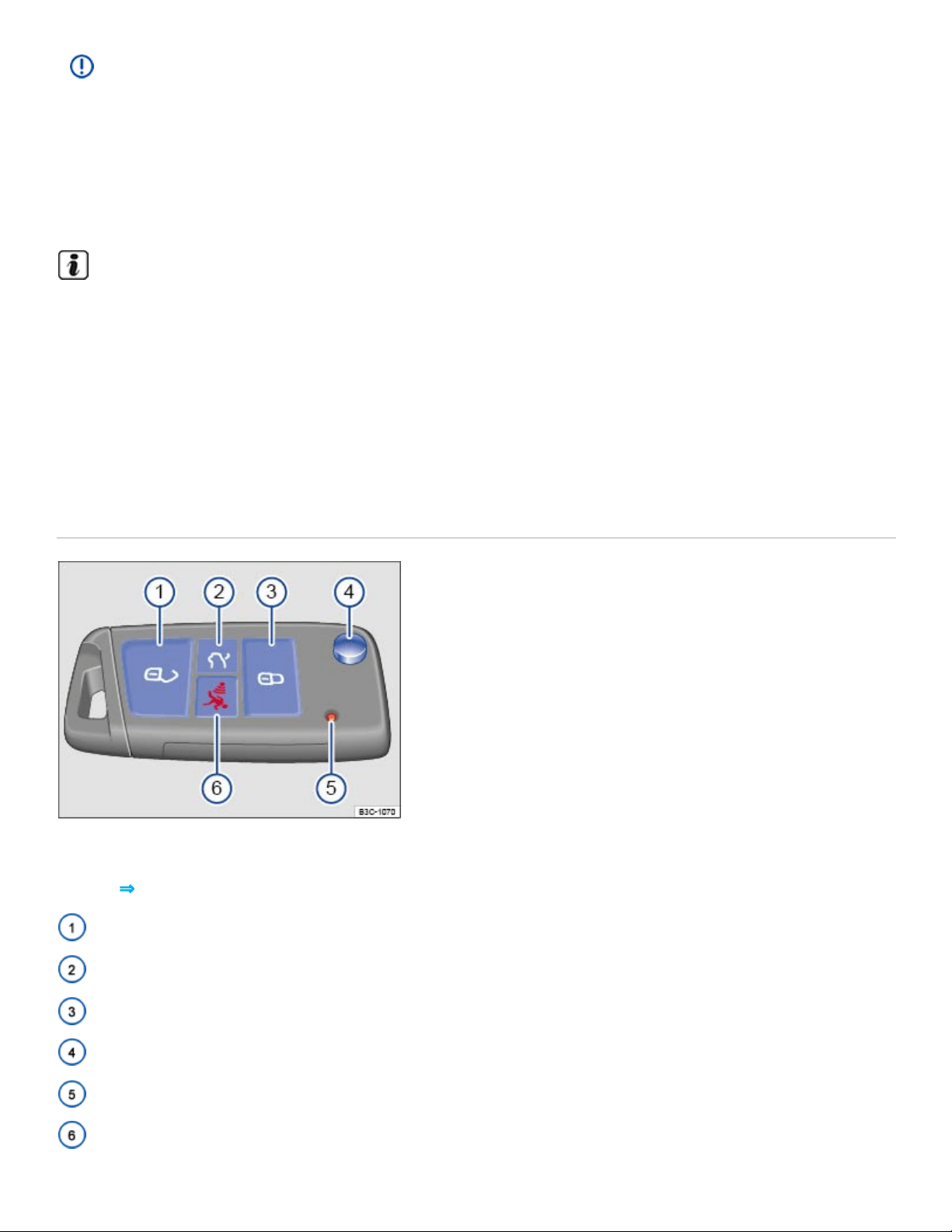
NOTE
To help prevent damage to the vehicle if you should have to push it a short distance by hand,
never push against spoilers, lights, body panels, windows, or similar parts. Concentrating force
on these parts of the vehicle can cause expensive damage that may not always be obvious right
away.
The vehicle battery will be drained if the emergency flashers are on for a long time – even if the
ignition is switched off.
Opening and closing
Vehicle key set
Vehicle key with key bit
Fig.47Vehicle key with key bit.
Key to ⇒Fig.47 :
Unlock the vehicle
Unlock the trunk lid
Lock the vehicle
Key bit release
Indicator light
Panic button
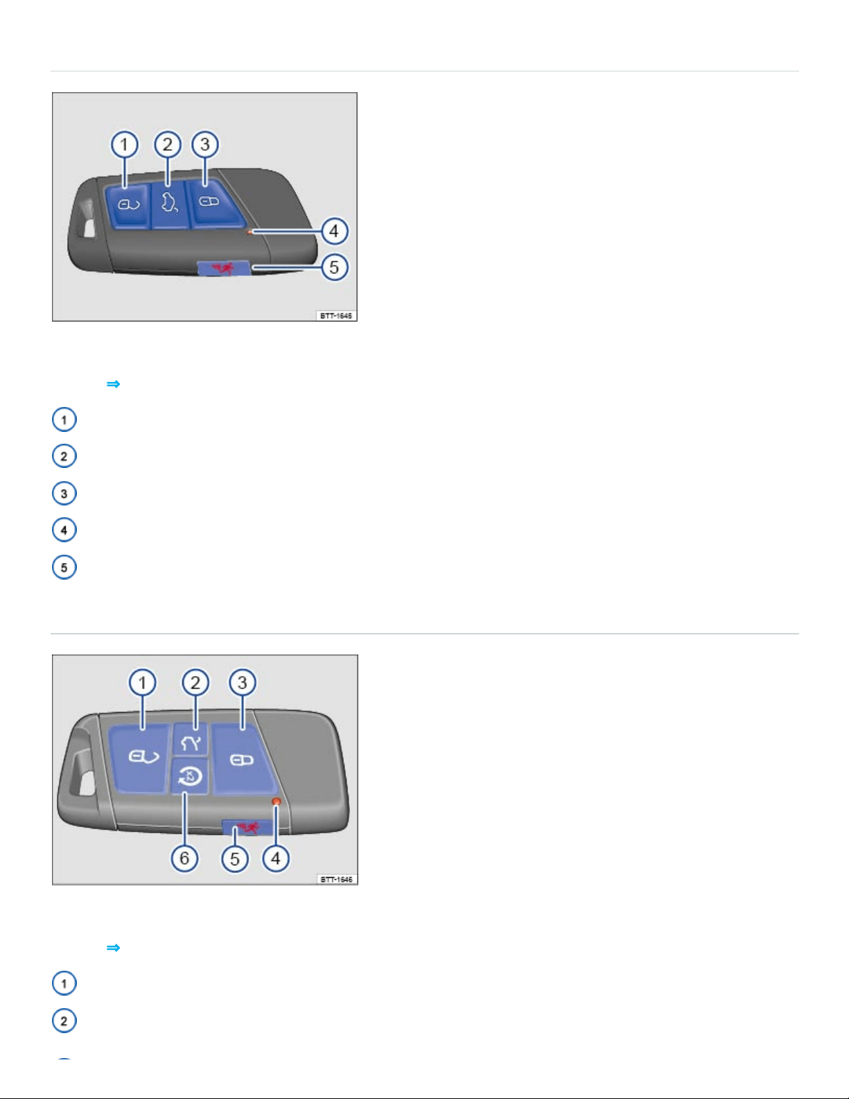
Vehicle key without key bit
Fig.48Vehicle key without key bit.
Key to ⇒Fig.47 :
Unlock the vehicle
Unlock the trunk lid
Lock the vehicle
Indicator light
Panic button
Vehicle key with Remote Start
Fig.49Vehicle key with Remote Start.
Key to ⇒Fig.47 :
Unlock the vehicle
Unlock the trunk lid

Lock the vehicle
Indicator light
Panic button
Remote Start button
Remote start button
Pressing the button two times after pressing the button activates the remote start feature
⇒Remote start feature .
Using the vehicle keys
The remote transmitter and battery are inside the remote control vehicle key. The receiver is inside
the passenger compartment. The operating range of the remote control vehicle key for a fresh battery
is several yards (meters) around the vehicle.
Unlocking or locking the vehicle from the outside
To unlock: Press the button on the remote control vehicle key.
To lock: Press the button on the remote control vehicle key.
To open the trunk lid: Press the or button on the remote control vehicle key.
The vehicle key unlocks or locks the vehicle only when the battery in the remote control vehicle key is
not too weak, and the remote control vehicle key is within a few yards/meters of the vehicle.
All turn signals flash once and the horn beeps once to confirm that the vehicle has been locked.
The horn beep (acoustic confirmation) can be disabled in the Vehicle settings menu in the
Infotainment system ⇒Infotainment system operation and displays .
All turn signals flash twice to confirm that the vehicle has been unlocked.
Indicator light in the remote control vehicle key
If a button on the remote control vehicle key is pressed briefly, the indicator light will flash once briefly.
If you push and hold a button, it flashes repeatedly.
Panic button

Press the panic button only in emergencies! After pushing the panic button, the horn will sound and
the turn signals will flash. Press the panic button again or press the button on the remote control
vehicle key to switch off the panic feature.
WARNING
Improper use of vehicle keys can result in serious personal injury.
Always take the key with you when you leave the vehicle. It can be used to start the engine
and operate vehicle systems such as the power windows, leading to serious personal injury.
Children or other unauthorized persons could also lock the doors and the trunk lid.
Never leave children, disabled persons, or anyone who cannot help themselves in the vehicle.
The doors can be locked with the remote control vehicle key. This could leave people trapped
in the vehicle in an emergency. Depending on the time of year, people trapped in the vehicle
can be exposed to very high or very low temperatures.
A closed vehicle can become very hot or very cold, depending on the season. Particularly in
the summer, heat buildup in the passenger and luggage compartment of a parked vehicle can
result in temperatures in the vehicle that are much higher than the outside temperatures.
Temperatures can quickly reach levels that can cause unconsciousness and death, particularly
to small children.
Never remove the key from the ignition switch or turn off the ignition with the starter button
while the vehicle is moving or rolling to a stop. The electronic steering column could suddenly
lock, you would not be able to steer, and you could lose control of the vehicle, crash, and seri‐
ously injure yourself and others.
NOTE
The remote control vehicle keys contain electrical components. Protect them from damage, mois‐
ture and rough handling.
Do not press the buttons on the remote control vehicle key unless you actually want to use the
function in question. Since terrain and conditions vary, pressing a button on the remote control
vehicle key when it is not necessary may unlock the vehicle or set off the panic alarm, even if you
think you are out of range.
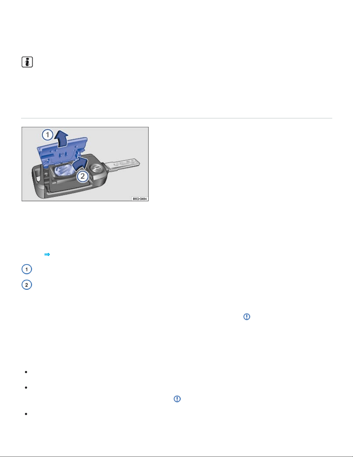
Some vehicles are equipped with electrically folding outside mirrors. When the vehicle is un‐
locked from the outside, the outside mirrors may automatically fold out, depending on settings in
the Infotainment system ⇒Infotainment system operation and displays .
A Declaration of Compliance with the United States FCC and Industry Canada regulations is on
⇒Declaration of Compliance, Telecommunications and Electronic Systems .
Replacing the remote control vehicle key battery (vehicles with a key bit)
Fig.50Remote control vehicle key: Opening the battery compartment cover and removing the old
battery.
The battery is in the back of the remote control vehicle key under a cover ⇒Fig.50① .
Key to ⇒Fig.50 :
Cover
Battery
Volkswagen recommends having the battery in the remote control vehicle key changed by an autho‐
rized Volkswagen dealer or an authorized Volkswagen Service Facility ⇒ .
When changing the battery, pay attention to the correct polarity and use the same type of battery.
Replacing the battery
Unfold the key bit on the remote control vehicle key.
Remove the cover on the back of the remote control vehicle key ⇒Fig.50① in the direction of the
arrow using a suitable object such as a coin ⇒ . This action may require some force.
Use a thin object to pry the battery out of the battery compartment ⇒Fig.50② .

Position the new battery and press it into the battery compartment (opposite direction of the ar‐
row) ⇒ .
Press the cover down (opposite direction of the arrow) until you hear it click into place.
DANGER!
20mm button cells and other lithium batteries will cause serious personal injury and even death
within a short time if swallowed.
Always keep remote control vehicle key fobs with batteries, spare batteries, as well as dead
button cell and larger 20mm batteries out of the reach of children.
Get medical attention immediately if you suspect that a battery has been swallowed.
NOTE
Changing the battery improperly can damage the remote control vehicle key.
Using the wrong battery can damage the remote control vehicle key. Replace a dead battery
with a new one that has the same voltage, size, and specifications.
Make sure the plus and minus poles of the battery are correctly positioned.
Dispose of old batteries in an environmentally responsible manner and keep them out of the
reach of children.
Batteries of the type used in your remote control vehicle key may contain Perchlorate Material.
Special handling may apply – see http://www.dtsc.ca.gov/hazardouswaste/perchlorate. Obey all
legal requirements regarding handling and disposal of these batteries. Authorized Volkswagen
dealers and authorized Volkswagen Service Facilities are familiar with the requirements, and we
recommend that you have them perform this service for you.
Replacing the remote control vehicle key battery (vehicles without a key bit)
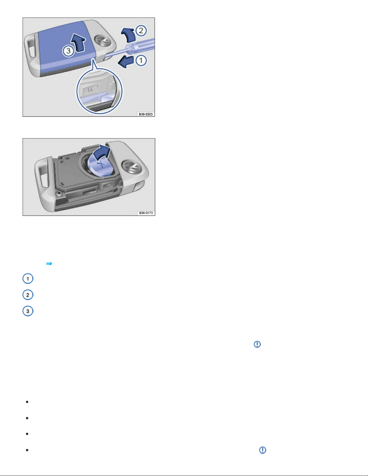
Fig.51Remote control vehicle key: Opening the battery compartment cover.
Fig.52Remote control vehicle key: Changing the battery.
The battery is on the back of the remote control vehicle key under a cover ⇒Fig.51① .
Key to ⇒Fig.51 :
Insert screwdriver to unlock the cover.
Turn the screwdriver in the direction of the arrow.
Cover on the back of the remote control vehicle key.
Volkswagen recommends having the battery in the remote control vehicle key changed by an autho‐
rized Volkswagen dealer or an authorized Volkswagen Service Facility ⇒ .
When changing the battery, pay attention to the correct polarity and use the same type of battery.
Replacing the battery
Remove the emergency key ⇒Emergency key .
Insert a small, flat-blade screwdriver into the emergency key slot.
Turn the screwdriver in the direction of the arrow until the cover opens ⇒Fig.51 ②.
Push the cover in the direction of the arrow ⇒Fig.51③ and remove ⇒ .

Use a thin object to pry the battery out of the battery out of the battery compartment ⇒Fig.52 .
Position the new battery and press it into the battery compartment (opposite direction of the ar‐
row) ⇒Fig.52 ⇒ .
Press the cover into place until you hear it click into place.
Replace the emergency key.
DANGER!
20mm button cells and other lithium batteries will cause serious personal injury and even death
within a short time if swallowed.
Always keep remote control vehicle key fobs with batteries, spare batteries, as well as dead
button cell and larger 20mm batteries out of the reach of children.
Get medical attention immediately if you suspect that a battery has been swallowed.
NOTE
Changing the battery improperly can damage the remote control vehicle key.
Using the wrong battery can damage the remote control vehicle key. Replace a dead battery
with a new one that has the same voltage, size, and specifications.
Make sure the plus and minus poles of the battery are correctly positioned.
Dispose of old batteries in an environmentally responsible manner and keep them out of the
reach of children.
Batteries of the type used in your remote control vehicle key may contain Perchlorate Material.
Special handling may apply – see http://www.dtsc.ca.gov/hazardouswaste/perchlorate. Obey all
legal requirements regarding handling and disposal of these batteries. Authorized Volkswagen
dealers and authorized Volkswagen Service Facilities are familiar with the requirements, and we
recommend that you have them perform this service for you.
Emergency key
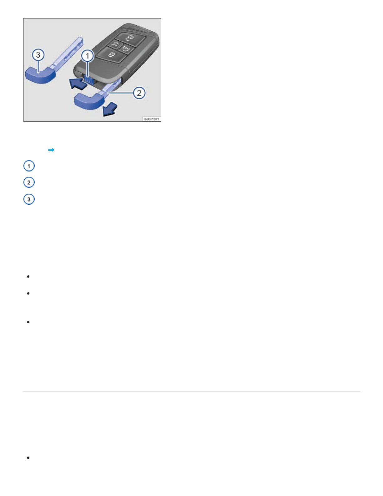
Fig.53Releasing the emergency key and removing it from the remote control vehicle key.
Key to ⇒Fig.53 :
Emergency key release.
Removing the emergency key.
Emergency key bit.
If your vehicle is equipped with Keyless Access, there is an emergency key ⇒Fig.53③ inside the re‐
mote control vehicle key fob.
You can do the following with the emergency key:
Lock and unlock the glove compartment.
Manually lock or unlock the vehicle ⇒Manually unlocking and locking the driver door , ⇒Manually
locking the passenger doors .
Activate the child safety lock ⇒Child safety lock .
To remove the emergency key: Move the sliding lock ⇒Fig.53① in the direction of the arrow. At the
same time, push the emergency key out of the slot in the remote control vehicle key in the direction of
the arrow ②.
Synchronizing the remote control vehicle key
If you cannot lock or unlock the vehicle with the vehicle key, synchronize the vehicle key as follows or
replace the vehicle key battery ⇒Replacing the remote control vehicle key battery (vehicles without a
key bit) or ⇒Replacing the remote control vehicle key battery (vehicles with a key bit) :
Stand next to the vehicle.

Press the button on the remote control vehicle key two times in quick succession.
Depending on equipment, unfold the key bit from the remote control vehicle key ⇒Vehicle key set
or remove the emergency key ⇒Emergency key .
Remove the cap from the door handle on the driver door ⇒Manually unlocking and locking the
driver door .
Stand next to the vehicle.
Press the button on the remote control vehicle key.
Manually unlock the vehicle using the key bit or emergency key ⇒Manually unlocking and locking
the driver door . The synchronization is complete.
If necessary, reinstall the emergency key in the key fob ⇒Emergency key .
Reinstall the cap.
Tips and troubleshooting
If the remote control vehicle key does not lock or unlock the vehicle
Things between the remote control vehicle key and vehicle, bad weather, as well as a weak battery
can reduce the operating range. Remote control vehicle key functions can also be temporarily dis‐
rupted by interference from transmitters near the vehicle that use the same frequency range (such as
radio equipment or mobile phones).
OR: The power locking system may have switched off for a brief period to help keep it from being
overloaded.
Close the driver door.
OR: Synchronize the vehicle key ⇒Synchronizing the remote control vehicle key .
If the indicator light in the vehicle key does not flash
If the indicator light in the remote control vehicle key does not come on when the button is pressed,
the battery inside the key must be replaced ⇒Replacing the remote control vehicle key battery (vehi‐
cles without a key bit) or ⇒Replacing the remote control vehicle key battery (vehicles with a key bit) .
If remote control vehicle keys need to be replaced
The vehicle identification number is required to get a replacement key or an additional remote control
vehicle key.

Each new vehicle key contains a microchip and must be coded with the data from the vehicle's elec‐
tronic immobilizer. A vehicle key will not work if it does not contain a microchip or contains a chip that
is not coded, even if the key bit was cut correctly.
You can obtain additional or duplicate remote control vehicle keys from authorized Volkswagen deal‐
ers, authorized Volkswagen Service Facilities, and from certain independent repair facilities and lock‐
smiths which are qualified to make remote control vehicle keys.
Each vehicle key must be programmed by an authorized Volkswagen dealer, an authorized
Volkswagen Service Facility, or certain independent repair facilities in order for it to work with your
vehicle.
To find the nearest qualified independent repair facility, locksmith, or Volkswagen dealer which can
cut and code replacement vehicle keys, call the VW Customer Care Hotline at 1-800-822-8987 or visit
http://www.vw.com and search for replacement keys.
Canadian customers can contact an authorized Volkswagen dealer or Volkswagen Service Facility or
call the Volkswagen Canada Customer CARE Center at 1-800-822-8987.
Keyless Access with push-button start
Introduction to the subject
In this chapter you will find information on the following subjects:
⇒Unlocking or locking the vehicle with Keyless Access
⇒Tips and troubleshooting
Your vehicle may be equipped with Keyless Access with push-button start, a keyless starting and
locking system that unlocks and locks the vehicle without active use of a remote control vehicle key.
All you have to do is touch a sensor surface on one of the front outside door handles or press the
Volkswagen emblem on the trunk lid when a valid remote control vehicle key is within range.
A Declaration of Compliance with the United States FCC and Industry Canada regulations is on
⇒Declaration of Compliance, Telecommunications and Electronic Systems .
Unlocking or locking the vehicle with Keyless Access
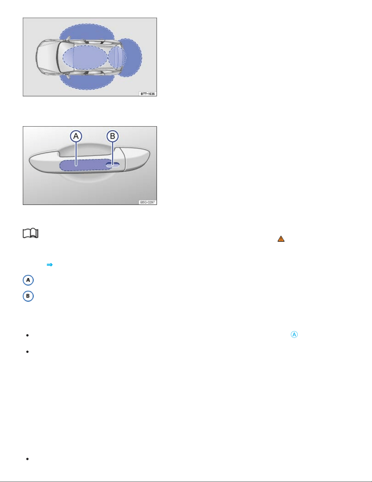
Fig.54Ranges of the Keyless Access system. Outside the vehicle: Unlocking range. Inside the vehi‐
cle: Starting range.
Fig.55Keyless Access system: Unlocking and locking sensors on the outside door handle.
Read and follow the introductory information and safety information first⇒ Introduction to the
subject
Key to ⇒Fig.55 :
Unlocking sensor
Locking sensor
Unlocking the vehicle
Grasp the door handle so that you touch the unlocking sensor surface ⇒Fig.55
Ⓐ
.
Open the door.
All turn signals flash twice to confirm that the vehicle has been unlocked.
If the vehicle is unlocked, it will lock again after a short time if you do not open one of the doors or the
trunk lid.
Locking the vehicle
Always switch off the engine and ignition and take the vehicle key with you.
Close the driver door.

Touch the sensor surface in the door handle ⇒Fig.55
Ⓑ
one time. The vehicle is locked.
All turn signals flash once to confirm that the vehicle has been locked.
Unlocking and locking the trunk lid
If the vehicle is locked and a valid remote control vehicle key is within range ⇒Fig.55 of the trunk lid,
it unlocks automatically when opened.
The trunk lid locks automatically when it is closed.
If the vehicle is completely unlocked, the trunk lid will not lock automatically when it is closed.
Temporarily deactivating Keyless Access
To help prevent the vehicle from being unlocked and started by an unauthorized person, Keyless
Access can be temporarily deactivated.
Lock the vehicle with the button on the remote control vehicle key.
Within 5 seconds, touch the sensor surface in the door handle on the driver or front passenger
door ⇒Fig.55
Ⓑ
.
Keyless Access is now temporarily deactivated.
To check that Keyless Access is deactivated, wait at least 10 seconds and then pull the door han‐
dle. The door should not open.
The vehicle can only be unlocked with the remote control vehicle key. Keyless Access is automatically
reactivated after the vehicle has been unlocked.
Convenience features
Your vehicle may be equipped with the convenience closing feature.
To use the convenience closing feature to close all power windows and the power sunroof, hold your
finger on the lock sensor surface on the outside of the door handle ⇒Fig.55
Ⓑ
for a few seconds un‐
til the windows and the power sunroof close.
Remove your finger from the lock sensor surface to stop the function.
Pinch protection is active during convenience closing of the windows and the power sunroof.

To help make sure that the vehicle stays locked after you press the locking sensor on the door
handle, the unlocking function on that door handle switches off for about 2seconds after locking
the vehicle.
A driver information message may appear in the instrument cluster display if there is a Keyless
Access system malfunction. See an authorized Volkswagen dealer or an authorized Volkswagen
Service Facility for assistance.
A driver information message appears in the instrument cluster display if there is no remote con‐
trol vehicle key inside the vehicle or if the system does not recognize the remote control vehicle
key. The key may not be recognized, for example, if it is covered by something that interferes with
the signal (such as a briefcase), or if the remote control vehicle key battery is weak. Electronic
devices such as mobile phones can also interfere with the signal.
The vehicle can only be locked if the automatic transmission is in the Park (P) position.
Depending on the vehicle settings, the entire vehicle will unlock when you touch the unlocking
sensor surface twice in a row, even if a single door was already unlocked.
Tips and troubleshooting
Read and follow the introductory information and safety information first⇒ Introduction to the
subject
If Keyless Access does not work
Dirt or road salt on the door handles can affect the way the door handle sensors work.
Clean the door handle sensors ⇒Exterior care and cleaning .
If all turn signals flash four times
To help prevent you from locking yourself out, the vehicle will not lock immediately in the following
situation:
When you press the lock button on the remote control vehicle key when a passenger door or the
trunk lid is still open.

AND you leave the remote control vehicle key you just used inside the vehicle when you close all
doors and the trunk lid.
The vehicle does not fully lock. All turn signals flash four times. Take the remote control vehicle key
out of the vehicle and lock the vehicle again.
Automatic deactivation of sensors
If the vehicle has not been unlocked or locked for a longer period of time, the sensors in the door han‐
dles are automatically switched off.
If a sensor on the door handle of a locked vehicle is touched too often, for instance by a bush or
hedge that rubs against the vehicle, that sensor may be switched off for a short time.
To reactivate the sensors:
Unlock the vehicle using the button on the remote control vehicle key.
NOTE
The door handle sensor surfaces can be activated by a strong stream of water or steam if a valid
vehicle key is within range of the vehicle.
If at least one power window is opened and the sensor is continuously activated, the conve‐
nience closing feature will automatically close the windows.
Doors and power locking system
Introduction to the subject
In this chapter you will find information on the following subjects:
⇒Indicator light in the driver door
⇒Automatic locking and unlocking
⇒Power locking and unlocking switches
⇒Manually unlocking and locking the driver door
⇒Manually locking the passenger doors

⇒Child safety lock
⇒Tips and troubleshooting
The power locking system lets you unlock and lock all doors, the trunk lid, and the fuel filler flap.
The doors can be locked manually if the remote control vehicle key or the power locking system is not
working ⇒Manually unlocking and locking the driver door .
The power locking system works properly only when all doors and the trunk lid are completely closed.
When the driver door is open, the vehicle cannot be locked with the remote control vehicle key.
For vehicles equipped with Keyless Access with push-button start, the vehicle can be locked only if
the ignition is switched off and the driver door is closed.
If a door is not closed properly, the vehicle icon appears in the instrument cluster display indicating a
door is open. Stop! Open and close the door again.
The vehicle icon may still be displayed even after the ignition is switched off. The instrument cluster
display goes out a short time after the vehicle has been locked.
WARNING
A door that is not closed properly may open suddenly when the vehicle is moving and cause se‐
vere injuries.
Stop immediately in a safe place and close the door.
Make sure that the door is safely and completely latched when closed. The closed door must
be flush with the surrounding auto body parts.
Open or close doors only if no one is in the way.
WARNING
A door kept open with the door stop may close in strong winds or on inclines and cause injuries.
Always hold doors by the door handle while opening and closing.
WARNING

Improper use of power locks can result in serious personal injury.
The power locking button locks all doors. Locking the doors from the inside can help prevent
unintended door opening during a collision and can also prevent unwanted entry from the out‐
side. Locked doors can, however, delay assistance to vehicle occupants and rescue from the
outside in an accident or other emergency.
Never leave children or anyone who cannot help themselves behind in the vehicle. All doors
can be locked from the inside with the power lock button. This could leave people trapped in
the vehicle in an emergency. Depending on the time of year, people trapped in the vehicle can
be exposed to very high or very low temperatures.
A closed vehicle can become very hot or very cold, depending on the season. Particularly in
the summer, heat buildup in the passenger and luggage compartment of a parked vehicle can
result in temperatures in the vehicle that are much higher than the outside temperatures.
Temperatures can quickly reach levels that can cause unconsciousness and death, particularly
to small children.
Never allow passengers to stay in a locked vehicle. In an emergency any person still inside the
vehicle might not be able to get out.
NOTE
When locking or unlocking the vehicle manually, remove parts carefully and install them again
correctly to avoid damaging the vehicle.
Certain settings are automatically saved by the driver personalization feature ⇒Driver
Personalization .
Indicator light in the driver door
Read and follow the introductory information and safety information first⇒ Introduction to the
subject
The indicator light for the power locking system is in the driver door.
If the vehicle is locked: The red LED light flashes for about 2seconds in short intervals, then slower.

The indicator light does not flash if the vehicle was locked with the power locking switch in the driver
door ⇒Power locking and unlocking switches .
Automatic locking and unlocking
Read and follow the introductory information and safety information first⇒ Introduction to the
subject
You can change certain power locking system settings in the Vehicle settings menu in the
Infotainment system ⇒Infotainment system operation and displays .
Automatic locking (Auto lock)
The vehicle locks automatically when it reaches a speed of about 10mph (15km/h). When the vehi‐
cle is locked, the indicator light comes on in the power locking button ⇒Power locking and unlock‐
ing switches .
Automatic unlocking (Auto unlock)
Auto unlock works only if the vehicle has been automatically locked with the Auto lock feature. When
one of the following conditions is met, the doors will unlock automatically.
The selector lever is in Park (P).
OR: The ignition is switched off.
OR: You open a door from inside the vehicle.
OR: The airbags inflate after a collision ⇒Tips and troubleshooting .
The indicator light goes out in the power locking button when the doors unlock ⇒Power locking
and unlocking switches .
Automatic unlocking after airbag inflation allows emergency responders to access the vehicle.
Depending on the settings for the power locking system that have been set in the Infotainment
system, it may be necessary to press the button on the remote control vehicle key twice to un‐
lock all doors and the trunk lid ⇒Infotainment system operation and displays .
Power locking and unlocking switches
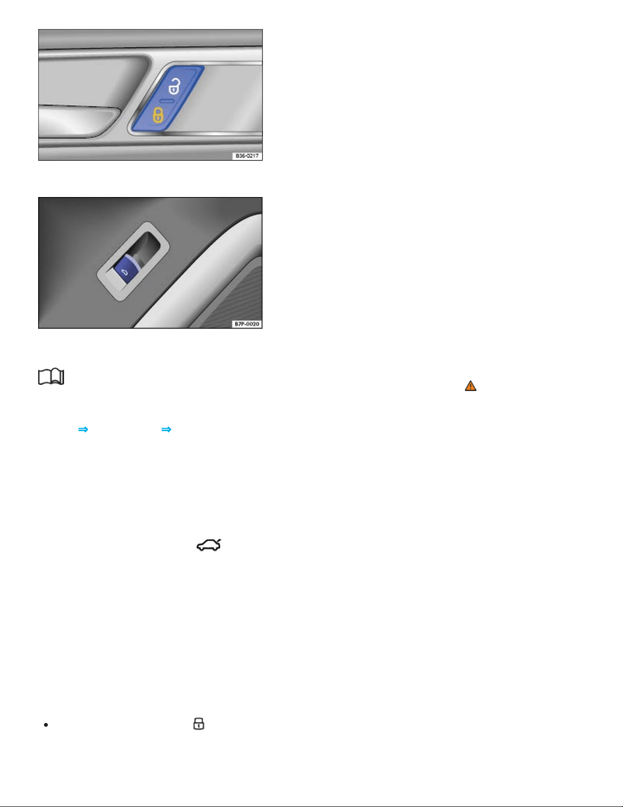
Fig.56In the driver and front passenger doors: Power locking button.
Fig.57In the driver door: Switch to open the trunk lid.
Read and follow the introductory information and safety information first⇒ Introduction to the
subject
Key to ⇒Fig.56 and ⇒Fig.57 :
Unlock the vehicle.
Lock the vehicle.
Open the trunk lid ⇒Fig.57 .
To open the trunk lid, pull the switch in the driver door up. The trunk lid opens automatically. All
doors stay locked.
The power locking button works whether the ignition is switched on or off but only when all doors are
closed.
If the vehicle is locked with the vehicle key, the power locking button is deactivated.
If the vehicle is locked with the power locking button:
The yellow indicator light in the power locking button comes on to indicate that all doors are
locked ⇒Fig.56 .
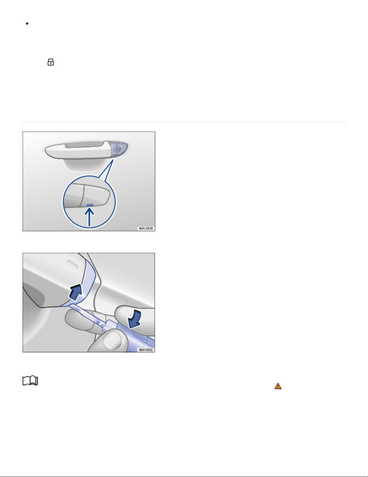
If the vehicle is equipped with an anti-theft alarm, the system is not turned on.
Doors can be unlocked and opened separately from inside the vehicle by pulling the door handle to
open the door. The rear passenger door handles need to be pulled twice to open the door. The indica‐
tor light goes out. The unopened doors and trunk lid stay locked and cannot be opened from the
outside.
An open driver door will not be locked. This helps keep the driver from being locked out of the vehicle.
Manually unlocking and locking the driver door
Fig.58Driver door: Concealed lock cylinder.
Fig.59Driver door handle: remove the lock cylinder cover.
Read and follow the introductory information and safety information first⇒ Introduction to the
subject
When the vehicle is locked manually, all doors are locked. When the vehicle is unlocked manually,
only the driver door will unlock. Note the instructions for the anti-theft alarm system ⇒Doors and
power locking system .

Depending on equipment, unfold the key bit from the remote control vehicle key ⇒Vehicle key set
or remove the emergency key ⇒Emergency key .
Insert the key bit from below into the opening of the cover cap on the driver door ⇒Fig.59 (ar‐
row) and lift the cover cap off. Grasping the door handle and pulling slightly makes it easier to re‐
move the cap.
Insert the key bit into the lock cylinder of the driver door and unlock or lock the door. If the larger
side of the vehicle key touches the door handle during locking or unlocking, either pull the door
handle slightly or reinsert the vehicle key in the lock cylinder with the opposite side facing up.
Reinsert the cover cap from top to bottom and press until it clicks into place. Grasping the door
handle and pulling slightly makes it easier to reinstall the cap.
Keyless Access ⇒Unlocking or locking the vehicle with Keyless Access is not activated if the vehicle
is locked manually.
Special considerations when unlocking manually
If the vehicle is equipped with an anti-theft alarm system, the alarm will sound when the driver
door is opened ⇒Doors and power locking system .
Switch on the ignition to switch off the alarm.
The electronic immobilizer recognizes a valid remote control vehicle key when the ignition is switched
on and deactivates the anti-theft alarm system.
The driver door can be unlocked separately from the inside the vehicle by pulling the door handle
to open the door.
The anti-theft alarm system, when installed, is not activated when the vehicle is locked manually
with the key bit ⇒Anti-theft alarm system .
Manually locking the passenger doors
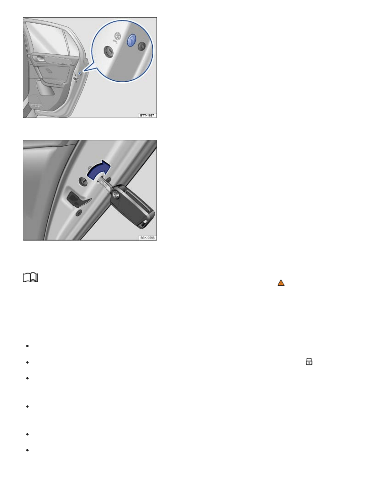
Fig.60on the rear passenger door: Manual lock, covered by a rubber seal.
Fig.61On the front side of the rear passenger side door: Locking the vehicle with the key bit in the
vehicle key.
Read and follow the introductory information and safety information first⇒ Introduction to the
subject
The passenger door and rear doors can each be locked manually. This will not activate the anti-theft
alarm system, if installed.
Open the door.
Remove the rubber seal on the front side of the door. The seal is marked with a lock .
Depending on equipment, unfold the key bit from the remote control vehicle key ⇒Vehicle key set
or remove the emergency key ⇒Emergency key .
Insert the key bit into the slot ⇒Fig.61 . On the passenger side doors, turn the key clockwise. On
the driver side rear door, turn the key counterclockwise.
Reinsert the rubber seal and completely close the door.
Make sure that the door is locked.
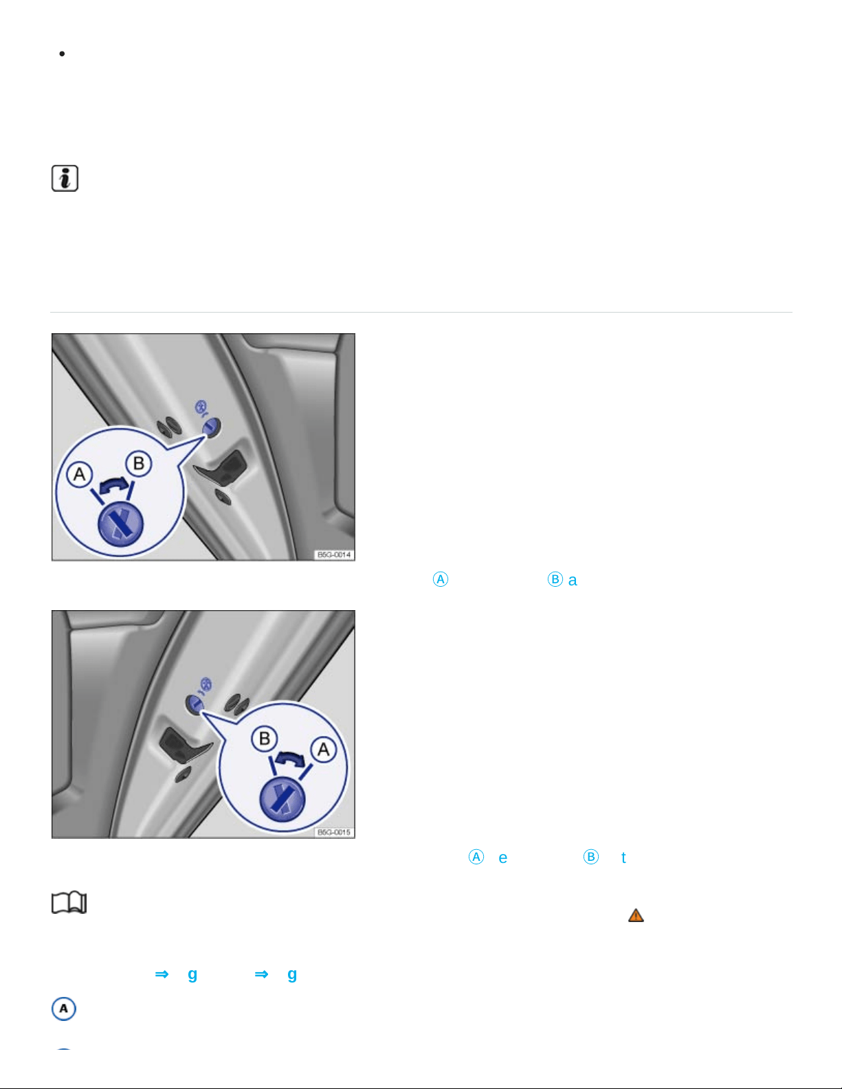
Have the vehicle checked immediately by an authorized Volkswagen dealer or an authorized
Volkswagen Service Facility.
A door that has been locked manually will be unlocked again if the vehicle is unlocked or the door is
opened from the inside.
The vehicle doors can still be unlocked and opened separately from inside the vehicle by pulling
the door handle to open the door.
Child safety lock
Fig.62In the rear driver side door: Child safety lock
Ⓐ
deactivated,
Ⓑ
activated.
Fig.63In the rear passenger side door: Child safety lock
Ⓐ
deactivated,
Ⓑ
activated.
Read and follow the introductory information and safety information first⇒ Introduction to the
subject
Slot position ⇒Fig.62 or ⇒Fig.63 :
Child safety lock deactivated.

Child safety lock activated.
The child safety lock keeps the rear doors from being opened from the inside, so that children cannot
open them accidentally.
When the child safety lock is activated, the rear doors can only be opened from the outside.
Activating or deactivating the child safety lock
Unlock the vehicle and open the respective rear door.
Depending on equipment, unfold the key bit from the remote control vehicle key ⇒Vehicle key set
or remove the emergency key ⇒Emergency key .
Using the key bit, move the slot into the desired position.
WARNING
When the child safety lock is activated, that rear door cannot be opened from the inside.
Never leave children, disabled persons, or anyone who cannot help themselves, in the vehicle
when locking the doors. This could result in people being locked in the vehicle. This could re‐
sult in people being trapped in the vehicle in an emergency. Depending on the time of year,
people trapped in the vehicle can be exposed to very high or very low temperatures.
A closed vehicle can become very hot or very cold, depending on the season. Particularly in
the summer, heat buildup in the passenger and luggage compartment of a parked vehicle can
result in temperatures in the vehicle that are much higher than the outside temperatures.
Temperatures can quickly reach levels that can cause unconsciousness and death, particularly
to small children.
Tips and troubleshooting
Read and follow the introductory information and safety information first⇒ Introduction to the
subject
If the red indicator light in the driver door lights up continuously
If the red LED light in the driver door flashes for about 2seconds in short intervals, then lights up con‐
tinuously for about 30seconds, there is a power locking system malfunction.
See an authorized Volkswagen dealer or an authorized Volkswagen Service Facility for
assistance.

If the turn signals do not flash to confirm locking
If you try to lock the vehicle and the turn signals do not flash to confirm locking:
At least one of the doors or the trunk lid is open.
If the vehicle locks itself automatically
If the vehicle was unlocked with the remote control vehicle key and the door or the trunk lid has not
been opened within several seconds, the vehicle is automatically locked again. This feature helps
prevent you from leaving the vehicle unlocked unintentionally.
Locking with a second vehicle key
If a vehicle with Keyless Access is locked from the outside using a second valid vehicle key, any key
inside the vehicle cannot start the engine ⇒Starting and stopping the engine . A key that was inside
the vehicle when it was locked from the outside can be reactivated by pressing the button on the
deactivated key.
Locking the vehicle after airbag inflation
If the airbags are activated during a collision, the entire vehicle is unlocked. Depending on the sever‐
ity of the damage, the vehicle can be locked after a collision when the airbags have deployed.
Switch the ignition off.
Open and close a door once.
Press the button on the power locking switch or on the remote control vehicle key.
If the vehicle battery is dead or weak, Keyless Access may not be able to lock or unlock the vehi‐
cle. The vehicle can be locked or unlocked manually.
If there is no valid vehicle key in the vehicle or it has not been detected, a text message will ap‐
pear in the instrument cluster display. This can happen if the vehicle key is subject to interference
by another radio signal or is covered by another item, for example, an aluminium case.
Anti-theft alarm system
Your vehicle is equipped with an anti-theft alarm system.

The anti-theft alarm system is automatically switched on when the vehicle is locked by pressing the
lock button on the remote control vehicle key.
The anti-theft alarm system sounds and the turn signals flash for up to 5minutes if the following oc‐
curs with respect to the locked vehicle:
When is the alarm triggered?
A door unlocked mechanically with the vehicle key bit is opened.
A door is opened from the inside after the vehicle has been locked from the outside with the re‐
mote control vehicle key.
Forcibly opening a door.
Forcibly opening the engine hood.
Forcibly opening the trunk lid.
Switching on the ignition with an invalid key.
Disconnecting the vehicle battery.
Deactivating the alarm
Unlock the vehicle with the unlock button on the remote control vehicle key.
OR: Switch on the ignition with a valid remote control vehicle key.
For vehicles with Keyless Access: Grasp one of the front door handles when a valid vehicle key is
in range.
After the alarm has stopped and the vehicle is opened again in the same or a different area that
is protected by the alarm, the alarm is triggered again. For example, the alarm will sound again if
the trunk lid is opened after one of the doors has been opened.
The anti-theft alarm system is not switched on when the vehicle is locked with the power lock
switch on the inside of the driver or front passenger doors.
If the driver door is mechanically unlocked using the vehicle key bit, only the driver door is un‐
locked, not the entire vehicle. Switching on the ignition switches off the anti-theft alarm system
and activates the central locking button.

If the vehicle battery is dead or weak, the anti-theft alarm system will not work properly.
Trunk lid
Introduction to the subject
In this chapter you will find information on the following subjects:
⇒Opening and closing the trunk lid manually
⇒Power operation of the trunk lid
⇒Sensor-controlled luggage compartment opener (Easy Open)
⇒Opening the trunk lid from inside the luggage compartment
⇒Tips and troubleshooting
The trunk lid is unlocked and locked together with the doors.
In vehicles with Keyless Access, the trunk lid is unlocked automatically ⇒Unlocking or locking the ve‐
hicle with Keyless Access .
If the trunk lid is not closed properly, the vehicle icon appears in the instrument cluster display indicat‐
ing the trunk lid is open. Stop! Open the trunk lid and then close it again.
The vehicle icon may still be displayed even after the ignition is switched off. The instrument cluster
display goes out a short time after the vehicle has been locked.
WARNING
Accidents and severe personal injuries can result if you unlock, open, or close the trunk lid when
someone is in the way.
Only open or close the trunk lid if no one is in the way.
Never close the trunk lid by pushing on the rear window with your hand. The rear window
could break and cause injuries.

After closing the trunk lid, always make sure that it is properly closed and locked so that it can‐
not open suddenly when the vehicle is moving. The closed trunk lid must be flush with the sur‐
rounding auto body parts.
Always keep the trunk lid closed while driving to help keep poisonous exhaust gas from being
drawn into the vehicle.
Never open the trunk lid when a luggage rack is installed and loaded. If, for example, there are
bicycles on a carrier on the trunk lid, it is possible that the trunk lid will be difficult to open. An
open trunk lid may fall on its own because of the additional weight. If necessary, prop open the
trunk lid. Remove the weight from the luggage rack first.
Close and lock the trunk lid and all doors when the vehicle is not in use. First, make sure that
no one is left inside the vehicle.
Never leave your vehicle unattended or let children play around your vehicle, especially when
the trunk lid is open. A child could crawl into the vehicle and pull the trunk lid shut, becoming
trapped and unable to get out. A closed vehicle can become very hot or very cold, depending
on the season. Particularly in the summer, heat buildup in the passenger and luggage com‐
partment of a parked vehicle can result in temperatures in the vehicle that are much higher
than the outside temperatures. Temperatures can quickly reach levels that can cause uncon‐
sciousness and death, particularly to small children.
Never leave children or anyone who cannot help themselves behind in the vehicle. They may
lock the vehicle with the vehicle key or the power locking button and lock themselves in.
Never let children play in or around the vehicle.
Never let anyone ride in the luggage compartment.
WARNING
If the trunk lid is not closed properly, it may open suddenly when the vehicle is moving and cause
severe injuries.
Stop immediately in a safe place and close the trunk lid.
Always make sure the trunk lid is securely latched after you close it.
NOTE
Before opening or closing the trunk lid, make sure there is enough room to do so, for example,
when the vehicle has a trailer or is in a garage.
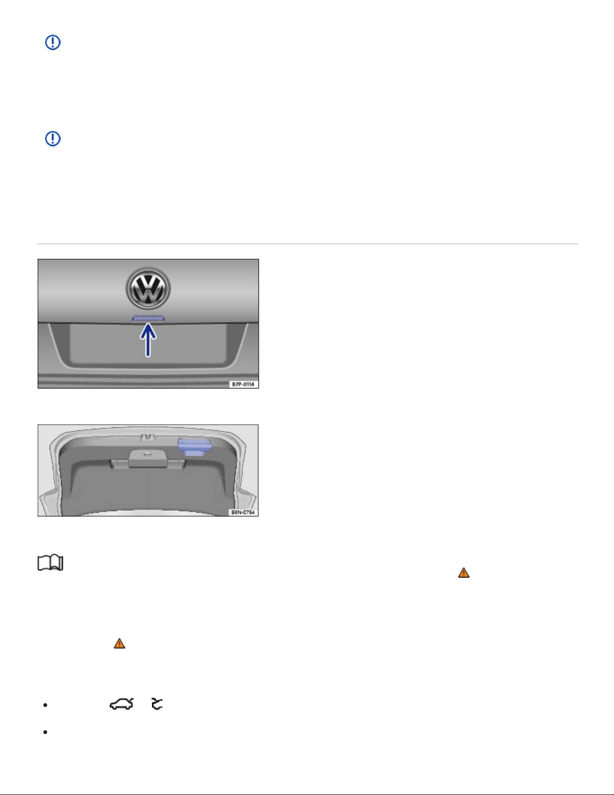
NOTE
Never use the gas-pressure strut to hold or clamp a load in place. This can damage the trunk lid
and make it impossible to close.
NOTE
Never use the rear windshield wiper or the rear spoiler to fix a load in place. This can damage the
trunk lid and cause the windshield wiper or spoiler to be torn off.
Opening and closing the trunk lid manually
Fig.64Opening trunk lid from the outside.
Fig.65Open trunk lid: Handle for closing the trunk lid.
Read and follow the introductory information and safety information first⇒ Introduction to the
subject
If necessary, remove anything secured to a luggage rack mounted onto the trunk lid before opening
the trunk lid ⇒ .
Unlocking and opening the trunk lid
Press the or button on the remote control vehicle key to unlock the trunk lid.
Press the button in the trunk lid ⇒Fig.64 (arrow) and pull up to open.

Closing the trunk lid
Grasp the handle in the trunk lid trim, pull the trunk lid down, and close it securely so that the latch
engages ⇒Fig.65 .
Check the trunk lid to make sure it is securely latched.
The trunk lid can be locked only when it is securely closed and latched.
The power locking system also locks the trunk lid.
A closed but unlocked trunk lid automatically locks at speeds above about 3 mph (5 km/h).
WARNING
Improper and unsupervised unlocking or opening of the trunk lid can cause severe injuries. Never
open the trunk lid when someone is in the way.
If a bicycle or luggage rack is installed on the trunk lid, it may be hard to see that the trunk lid
is unlatched. An unlatched trunk lid may open suddenly when the vehicle is moving.
WARNING
Improper or unsupervised closing of the trunk lid can cause severe injuries. Never close the trunk
lid when someone is in the way.
Never leave your vehicle unattended or let children play around your vehicle, especially with
the trunk lid left open. A child could crawl into the vehicle and pull the trunk lid shut, becoming
trapped and unable to get out. A closed vehicle can become very hot or very cold depending
on the season. Temperatures can quickly reach levels that can cause unconsciousness or
death, particularly to small children.
When closing the trunk lid, be careful to remove your hands out of the path of the trunk lid in
time.
NOTE
Before opening or closing the trunk lid, make sure there is enough room to do so, as for example
when the vehicle has a trailer or is in a garage.
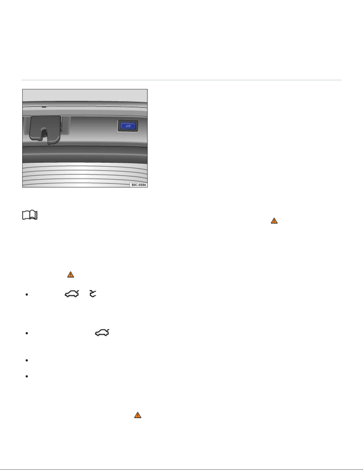
If you unlock the vehicle with the vehicle key, but do not open either a door or the trunk lid within
several seconds, the vehicle automatically locks again. This feature helps prevent you from leav‐
ing the vehicle unlocked unintentionally.
Power operation of the trunk lid
Fig.66Button in the open trunk lid.
Read and follow the introductory information and safety information first⇒ Introduction to the
subject
Opening the trunk lid
If necessary, remove anything secured to a luggage rack mounted onto the trunk lid before opening
the trunk lid ⇒ .
Press the or button on the remote control vehicle key for about a second until the trunk lid
automatically opens. If the doors are locked, only the trunk lid is unlocked and the doors stay
locked.
OR: Pull the switch in the driver door up ⇒Fig.57 . The selector lever must be in position
(P). The switch also works when the ignition is switched off.
OR: Press the button on the trunk lid ⇒Fig.64 (arrow).
For vehicles with Keyless Access and sensor-controlled opening (Easy Open): The trunk lid can
be opened by moving your foot in the sensor range under the middle of the rear bumper (Easy
Open) ⇒Sensor-controlled luggage compartment opener (Easy Open) .
The trunk lid opens automatically ⇒ .
Closing the trunk lid

Press the button in the open trunk lid ⇒Fig.66 ⇒ .
OR: Pull up and hold the switch in the driver door until the trunk lid is completely closed. The
ignition must be switched on.
For vehicles with Keyless Access: Press the or button in the remote control vehicle key.
You must be within sensor range ⇒Fig.55 behind the vehicle for the trunk lid to close. If you are
not behind the vehicle, the turn signals will flash, but the trunk lid will not close.
For vehicles with Keyless Access: If you close the trunk lid after the vehicle is locked, but the vehi‐
cle key you just used is still inside the vehicle, the trunk lid will not fully close and all turn signals
flash four times. If you then close the trunk lid by hand, the vehicle will not lock immediately. All
emergency flashers blink four times.
OR: Pull down on the handle on the inside of the trunk lid ⇒Fig.65 . The trunk lid will then close
by itself ⇒ .
Stopping the trunk lid opening or closing process
The opening and closing of the trunk lid can be stopped as follows:
Press the or button on the remote control vehicle key or the button on the trunk lid,
or pull the switch in the driver door while the trunk lid is opening or closing.
Pressing the or button on the remote control vehicle key or the button on the trunk
lid, or pulling the switch in the driver door again makes the trunk lid fully open or close.
Warning chime
A warning chime sounds when the trunk lid is opened or closed from inside the vehicle or by using the
remote control vehicle key.
Saving the opening angle
If space behind or above the vehicle is limited, you can change the opening angle.
Stop the opening process at the desired opening angle.
Press the button in the open trunk lid ⇒Fig.66 until the emergency flashers blink and a
chime sounds.
The new opening angle is changed and saved ⇒ .
Resetting the opening angle
To completely open the trunk lid again, you must reset the original angle.

Unlock the trunk lid and open it to the saved opening angle.
Manually push the trunk lid open as far as it will go. This requires some strength.
Press the button in the open trunk lid ⇒Fig.66 until the emergency flashers blink and a
chime sounds.
The opening angle is reset.
WARNING
Improper or unsupervised closing of the trunk lid can cause severe injuries.
Never leave your vehicle unattended or let children play around your vehicle, especially with
the trunk lid left open. A child could crawl into the vehicle and pull the trunk lid shut, becoming
trapped and unable to get out. A closed vehicle can become very hot or very cold depending
on the season. Temperatures can quickly levels that can cause unconsciousness or death,
particularly to small children.
WARNING
A closed trunk lid cannot open completely and an open trunk lid cannot close automatically if a
luggage rack is installed on it or if it is covered by a heavy layer of snow. In this case, you will
have to hold the trunk lid or prop it up to keep it open.
Remove any snow or luggage mounted on the trunk lid before opening the trunk lid.
NOTE
Before opening or closing the trunk lid, make sure there is enough room to do so, as for example
when the vehicle has a trailer or is in a garage.
NOTE
If the system is operated too often in succession, it will shut itself off to help prevent overheating.
The feature can be used again as soon as the system has cooled down. In the meantime, the
trunk lid can be opened or closed by hand, though this requires some strength.
If the vehicle battery or the fuse is blown when the trunk lid is open, the trunk lid system must
be reset. To reset the trunk lid, it must be manually closed once.
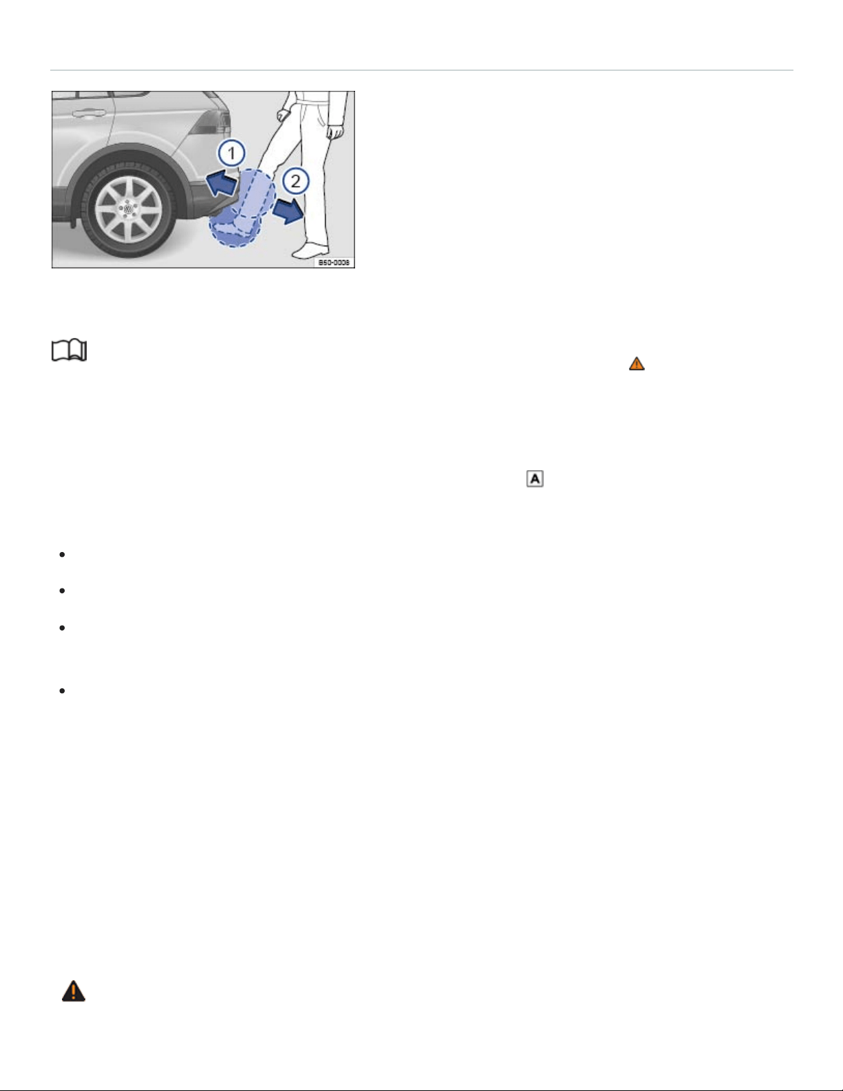
Sensor-controlled luggage compartment opener (Easy Open)
Fig.67Keyless Access locking and starting system: Opening the sensor-controlled trunk lid (Easy
Open).
Read and follow the introductory information and safety information first⇒ Introduction to the
subject
If your vehicle has Keyless Access, it may also be equipped with the Easy Open feature.
When a valid vehicle key is within range of the trunk lid ⇒Fig.55 , you can open the trunk lid by
moving your foot within the sensor’s range below the middle of the rear bumper.
Switch off the ignition.
Stand about 2ft. (60cm) behind the middle of the rear bumper.
Move your foot under the middle of the rear bumper in a kicking motion ⇒Fig.67 , ① then ②
(arrows).
Move your foot back so that you are standing firmly on both feet again. It is not necessary to con‐
tact the vehicle when you make this kicking motion.
If the trunk lid does not open, wait a few seconds and try again.
If the vehicle was completely locked beforehand, the trunk lid will lock again automatically after clos‐
ing if there is no valid vehicle key inside the vehicle.
Switching Easy Open on and off
Easy Open can be switched on or off in the Vehicle settings menu in the Infotainment system
⇒Infotainment system operation and displays .
WARNING
Careless use of the Easy Open feature can cause falls and serious personal injury
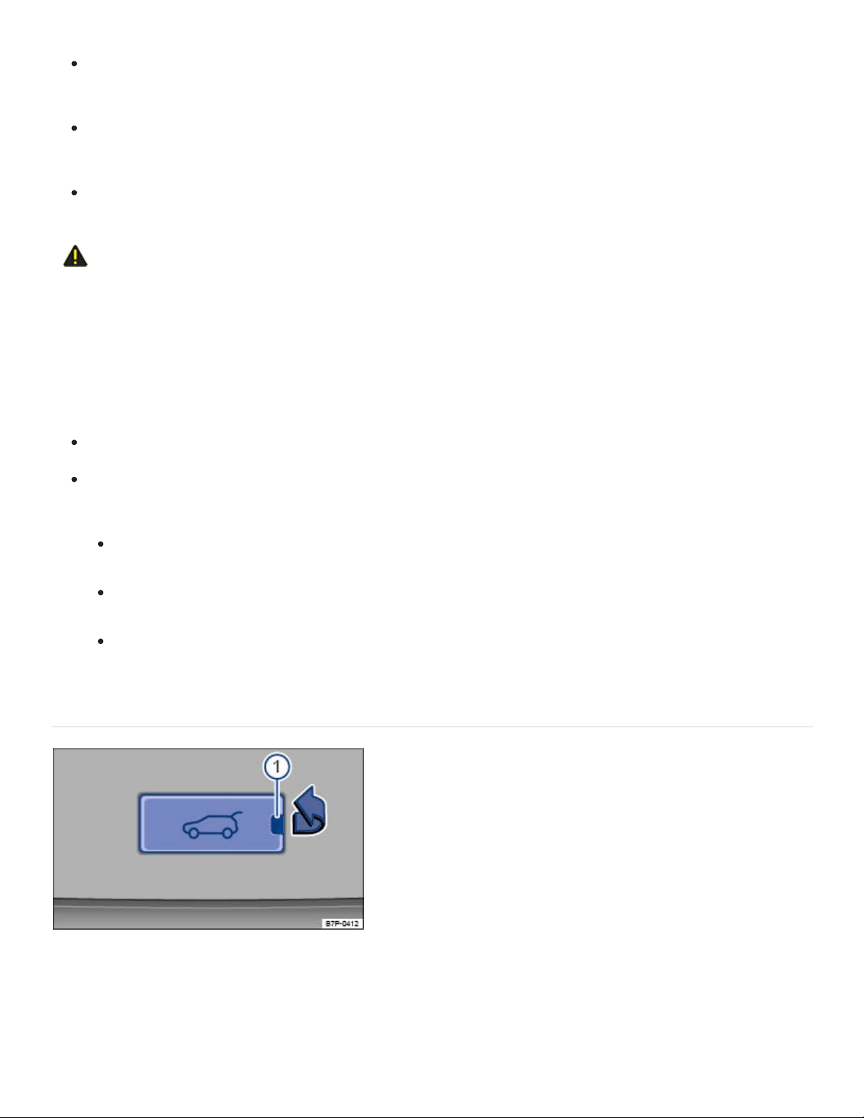
Always make sure you have firm footing when using the Easy Open feature, and that the sur‐
face you are standing on is not uneven or slippery.
Always remember that it will be necessary for you to move backwards to let the trunk lid open.
Be careful not to lose your balance, particularly when holding things in your hands.
Never use the Easy Open feature unless you can use it safely.
CAUTION
If a valid vehicle key is within range of the trunk lid, the Easy Open feature can deploy uninten‐
tionally in some cases and open the trunk lid: for example, when sweeping the ground or floor be‐
low the rear bumper, if there is a strong stream of water or steam, or when carrying out mainte‐
nance or repairs around the rear bumper. If the trunk lid opens unintentionally, it can injure any‐
one or damage anything in its way.
Never leave a valid vehicle key within range of the trunk lid unattended.
Always turn off the Easy Open feature in the vehicle settings menu Vehicle settings menu in
the following situations:
Before carrying out any maintenance or repairs on the vehicle.
Before washing the vehicle.
Before mounting a bicycle rack or connecting a trailer hitch to the vehicle.
Opening the trunk lid from inside the luggage compartment
Fig.68Inside the luggage compartment: Cover for manually unlocking the trunk lid.

Fig.69Inside the luggage compartment behind the cover: Opening the trunk lid.
Read and follow the introductory information and safety information first⇒ Introduction to the
subject
The trunk lid can be opened manually if the vehicle battery is discharged or if there is a fault in the
locking system.
If necessary, fold the third row seat backrest forward ⇒Seat functions .
Remove luggage to reach the trunk lid from the inside.
Remove the cover in the lower section of the interior trunk lid in the direction of the arrow
⇒Fig.68 . To do so, insert a suitable object such as the screwdriver in the vehicle tool kit in the
opening ① in the cover.
Insert a suitable object, such as the screwdriver in the vehicle tool kit, into the opening in the trunk
lid trim and press the colored release lever in the direction of the arrow ⇒Fig.69 to unlock the
trunk lid. At the same time, push the trunk lid out until it opens.
Open the trunk lid using increased force.
Tips and troubleshooting
Read and follow the introductory information and safety information first⇒ Introduction to the
subject
If the trunk lid does not open or close
Check whether the trunk lid is blocked by an obstacle. The trunk lid can still be moved by hand
with increased force.
If the trunk lid is electrically opened and closed too often within short time, the power drive
switches off automatically to prevent overheating. Until the power drive has cooled down, open
and close the trunk lid by hand using increased force.

If a factory-installed trailer hitch is connected to the vehicle electrically, then only the button in the
trunk lid is active. The switch in the driver door and the button on the remote control vehicle key
are deactivated.
The trunk lid must be closed by hand if the 12Volt vehicle battery or fuse is disconnected or if the
electrical system is not working.
If all turn signals flash four times
To help prevent you from locking yourself out, vehicles with Keyless Access will not lock immediately
in the following situation:
When you press the lock button on the remote control vehicle key when a passenger door or the
trunk lid is still open, and
You leave the remote control vehicle key you just used inside the vehicle when you close all doors
and the trunk lid.
The vehicle does not fully lock. All turn signals flash four times. Take the remote control vehicle key
out of the vehicle and lock the vehicle again.
If the trunk lid is stiff
At temperatures below +32°F (0°C), the trunk lid may not open automatically. It will be necessary to
lift it by hand.
If sensor-controlled opening (Easy Open) is not working
Make sure the ignition is switched off.
Clean the sensors in the rear bumper.
Unhitch the trailer ⇒Trailer towing .
An aftermarket trailer hitch has been installed.
During heavy rain, EasyOpen may have a delayed reaction or be completely deactivated to pre‐
vent accidental activation.
Power windows
Opening or closing power windows
Using the power window switches

Opening: Press the switch.
Closing: Pull the switch.
Stopping automatic movement: Press/pull the respective switch again.
Activating the safety switch for the rear windows: Press the safety switch in the driver door to
deactivate the power windows in the rear doors. The yellow indicator light in the switch comes on.
You can still use the power windows for several minutes after the ignition is switched off as long as
the driver or front passenger door has not been opened. When the vehicle key has been removed
from the ignition and the driver door has been opened, the power windows cannot be opened or
closed.
One-touch opening and closing
The one-touch feature automatically opens or closes a power window all the way. The window switch
does not have to be held.
For one-touch opening: Press the switch for the window down briefly as far as it goes.
For one-touch closing: Pull the switch for the window up briefly as far as it goes.
Stopping automatic movement: Pull/press the switch again.
Convenience opening and closing
Your vehicle may be equipped with the convenience opening and closing feature, which lets you open
and close the windows and the power sunroof when the ignition is switched off:
Convenience opening from inside the vehicle: Push down and hold the switch for the driver win‐
dow until all windows open and the sunroof tilts.
Convenience closing for vehicles with Keyless Access: Hold your finger on the lock sensor sur‐
face on the outside of the door handle for a few seconds until the windows and the sunroof close
⇒Unlocking or locking the vehicle with Keyless Access .
Release the switch or remove your finger from the lock sensor surface to stop convenience open‐
ing or closing.
All turn signals flash twice when the windows and sunroof are completely closed.
You can configure settings for the convenience opening feature in the Vehicle settings menu in the
Infotainment system ⇒Infotainment system operation and displays .

WARNING
Improper use of power windows can result in serious personal injury.
Never let anyone get in the way of a power window when closing it.
When locking the vehicle from the outside, make sure that no one, especially children, stays in
the vehicle. The windows will not open in case of an emergency.
Always switch off the engine and the ignition and take the key with you when you leave the ve‐
hicle. You can still use the power windows for several minutes after the ignition is switched off
as long as the driver or front passenger door has not been opened.
Always use the safety switch when children are in the back seat to disable the rear power win‐
dows and keep them from being opened and closed.
Never leave children or disabled persons in the vehicle – particularly if the ignition is on or a
remote control vehicle key is also in the vehicle. Unsupervised use of the remote control vehi‐
cle key makes it possible to lock the vehicle, start the engine, turn on the ignition, and operate
the windows.
NOTE
If you leave the windows open, rain or other precipitation may enter the vehicle from outside and
can damage the vehicle interior.
If the power windows malfunction, the one-touch feature, as well as pinch protection may not
work properly. See an authorized Volkswagen dealer or authorized Volkswagen Service Facility
right away.
Power window pinch protection
Pinch protection can help reduce the risk of pinching injuries when closing a power window ⇒ . If
one-touch window closing meets resistance or there is something in the way, the window will stop and
go down again.
Check why the window did not close.
Try one-touch window closing again.

If the window meets resistance a second time, so that it stops and goes back down, one-touch
closing is switched off for about 10seconds.
If you pull the power window button up all the way and hold it during this 10second interval, the
window will close without pinch protection⇒ .
Closing the window without pinch protection
Try to close the window again within 10seconds by holding the switch. Pinch protection is
turned off for a short distance in the window track!
If closing takes longer than about 10seconds, pinch protection is turned on again. The window
stops again if there is resistance.
If the window still will not close, please see an authorized Volkswagen dealer or an authorized
Volkswagen Service Facility.
WARNING
Without pinch protection, power windows will close with enough force to cause serious personal
injury.
Always be careful when closing power windows.
Always make sure that no one is in the way when overriding pinch protection to close power
windows!
Pinch protection cannot prevent fingers or other parts of the body from being pressed against
the window frame; injuries may result.
Pinch protection is also active during convenience closing of the windows and the power sunroof
⇒Opening or closing power windows .
Tips and troubleshooting
If the one-touch feature does not work
If the vehicle battery is disconnected or dies when the windows are not completely closed, the one-
touch feature will not work and must be reactivated after the vehicle battery has been recharged or
replaced:
Switch on the ignition.
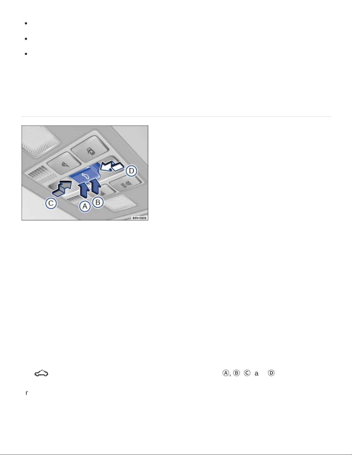
Close all windows and doors.
Pull the switch for the respective window up and hold it for at least 2seconds in this position.
Release the switch, pull up and hold again. The one-touch feature is now reactivated.
The one-touch feature can be reactivated for one or more windows at the same time.
Power sunroof
Opening or closing the power sunroof
Fig.70In the headliner: Power sunroof switch.
Depending on equipment, your vehicle may be equipped with a Panoramic sliding and tilting sunroof.
The sunroof consists of two glass pieces. The rear glass piece cannot be opened.
You must switch on the ignition to operate the power sunroof. After switching off the ignition, you can
still open or close the power sunroof for several minutes as long as the driver or front passenger door
has not been opened.
The sunshade opens automatically with the sunroof if it is in front of the sunroof. The sunshade does
not close with the sunroof, but instead stays in the previous position. Only when the sunroof has been
closed can the sunshade be completely closed by hand.
The switch ⇒Fig.70 has 2 detents for each switch position (
Ⓐ
,
Ⓑ
,
Ⓒ
, and
Ⓓ
).
Press the switch to the first detent to completely or partially tilt, open, or close the sunroof. Press the
switch briefly to the second detent to switch on the one-touch feature (automatic operation). Press the
switch again to stop the one-touch feature.

Tilt the power sunroof: Press the rear area of the switch
Ⓑ
upward to the first detent. Briefly press
the switch to the second detent to tilt the sunroof with the one-touch feature.
Close the tilted sunroof: Pull the rear area of the switch
Ⓐ
upward to the first detent. Briefly press
the switch to the second detent to close the tilted sunroof with the one-touch feature.
Stop the one-touch feature during tilting/closing: Press the button again at position
Ⓐ
or
Ⓑ
Open the power sunroof: Press the switch rearward
Ⓒ
to the first detent. Briefly press the switch
to the second detent to open the roof with the one-touch feature.
Close the power sunroof: Press the switch forward
Ⓓ
to the first detent. Briefly press the switch to
the second detent to close the sunroof with the one-touch feature.
Stop the one-touch feature during opening/closing: Press the switch again at
Ⓒ
or
Ⓓ
.
WARNING
Improper use of the power sunroof can result in serious personal injury.
Always make sure that no one is in the way of the power sunroof when it is closing.
Always switch off the engine and the ignition and take the key with you when you leave the
vehicle.
Never leave children or disabled persons in the vehicle – particularly if the ignition is on or a
remote control vehicle key is also in the vehicle. Unsupervised use of the remote control vehi‐
cle key makes it possible to lock the vehicle, start the engine, turn on the ignition and operate
the sunroof.
You can still open or close the power sunroof for several minutes after you switch off the igni‐
tion, as long as the driver or front passenger door has not been opened.
NOTE
To help prevent damage, remove ice and snow from the sunroof before opening or tilting it in
winter weather.
Always close the sunroof before leaving the vehicle or if it begins raining. If the sunroof is open
or tilted, rain could enter the vehicle interior and cause extensive damage to the electrical sys‐
tem. This could result in further vehicle damage.

Remove leaves and other objects from the sunroof guiderails regularly either by hand or using a
vacuum cleaner.
Certain settings are automatically saved by the driver personalization feature ⇒Driver
Personalization .
Convenience opening and closing of the power sunroof
Convenience opening and closing
Your vehicle may be equipped with the convenience opening and closing feature, which lets you open
and close the windows and the power sunroof when the ignition is switched off:
Convenience opening from inside the vehicle: Push down and hold the switch for the driver win‐
dow until all windows open and the sunroof tilts.
Convenience closing for vehicles with Keyless Access: Hold your finger on the lock sensor sur‐
face on the outside of the door handle for a few seconds until the windows and power sunroof
close ⇒Unlocking or locking the vehicle with Keyless Access .All turn signals flash twice when the
windows and sunroof are completely closed.
Release the switch or remove your finger from the lock sensor surface to stop convenience open‐
ing or closing.
You can configure settings for the convenience opening feature in the Vehicle settings menu in the
Infotainment system ⇒Infotainment system operation and displays .
Pinch protection for the power sunroof
Pinch protection can help reduce the risk of pinching injuries when closing the power sunroof ⇒ . If
the power sunroof closing meets resistance or there is something in the way, the power sunroof
opens again immediately.
Check why the power sunroof did not close.
Try to close the power sunroof again.
If the power sunroof cannot close, the power sunroof will open again immediately. For a few sec‐
onds after the sunroof has opened, it can be closed without pinch protection.
Closing the power sunroof without pinch protection

Press the button ⇒Fig.70 within about 5 seconds after the sunroof has stopped and hold it
in the direction of the arrow
Ⓓ
at the second detent until the power sunroof closes completely.
The power sunroof will now close without pinch protection!
If the power sunroof still will not close, please see an authorized Volkswagen dealer or an autho‐
rized Volkswagen Service Facility.
WARNING
Without pinch protection, the power sunroof will close with enough force to cause serious per‐
sonal injury.
Always be careful when closing the power sunroof.
Always make sure that no one is in the way when overriding the pinch protection to close the
power sunroof!
Pinch protection cannot prevent fingers or other parts of the body from being pressed against
the edge of the roof; injuries may result.
Pinch protection is also active during convenience closing of the windows and the power sunroof
⇒Convenience opening and closing of the power sunroof .
If the power sunroof malfunctions, pinch protection may not function properly. See an authorized
Volkswagen dealer or an authorized Volkswagen Service Facility for assistance.
Tips and troubleshooting
If the power sunroof does not close
You must switch on the ignition to operate the power sunroof. After switching off the ignition, you
can still open or close the power sunroof for several minutes as long as the driver or front passen‐
ger door has not been opened.
If your power sunroof will not close properly, do not try to close it yourself, doing so can cause se‐
rious and expensive damage that will not be covered by any Volkswagen Limited Warranty.
Special knowledge and tools are required to close the power sunroof if it will not close on its own.
To help prevent damage to the sunroof, have an authorized Volkswagen dealer or an authorized
Volkswagen Service Facility help you close and repair the power sunroof.

HomeLink Universal Transmitter
Introduction to the subject
In this chapter you will find information on the following subjects:
⇒Programming the HomeLink® Universal Transmitter
⇒Using the HomeLink® Universal Transmitter
⇒Tips and troubleshooting
Your vehicle may be equipped with a HomeLink Universal Transmitter, which can be used to
open/close an automatic garage door or gate, switch on a house alarm, or control a lighting system or
other devices. Such devices usually come with a hand-held remote control that sends a signal to a
controller to operate the device.
These instructions will help you program the HomeLink Universal Transmitter in your vehicle so that
you will not have to use the hand-held remote control that was supplied with the garage door opener
or other device inside your vehicle.
Fixed code or rolling code
The garage door opener or other device may work with either a fixed or rolling code. For garage door
openers or other devices with rolling codes, the HomeLink Universal Transmitter must be synchro‐
nized after programming the device.
Compatibility
Volkswagen recommends that you consult an authorized Volkswagen dealer or authorized
Volkswagen Service Facility about compatible devices before you buy a garage door opener or other
device that you want to control with the HomeLink Universal Transmitter.
The HomeLink Universal Transmitter can be programmed to the radio frequency codes of most cur‐
rent hand-held remote controls.
Safety switches are mandatory for garage door openers.
WARNING
®
®
®
®
®
®

Improper use of the HomeLink Universal Transmitter can cause serious or even fatal personal
injury.
Garage doors operate with enough force to cause serious personal injury.
Never let anyone get in the way of a garage door when it is opening or closing.
When programming the HomeLink Universal Transmitter, you may be operating a garage
door or estate gate. Always make sure that people and objects are out of the way to help pre‐
vent serious personal injury or property damage.
When operating the training button on a garage door opener with a rolling code, you will need
to stand on a ladder or step-stool. Always take extra precautions to prevent falls and serious
injury.
Never use the HomeLink Universal Transmitter with any garage door opener that does not
have the safety stop-and-reverse feature, as required by federal safety standards. This in‐
cludes any garage door opener model manufactured before April 1, 1982.
A garage door opener that cannot detect an object, signaling the door to stop and reverse,
does not meet current federal safety standards. Using a garage door opener without these fea‐
tures increases the risk of serious injury or death.
Follow the installation manual and the included safety information from the manufacturer when
using the remote-controlled garage door opener or electrical drive.
A Declaration of Compliance with the United States FCC and Industry Canada regulations ison
⇒Declaration of Compliance, Telecommunications and Electronic Systems .
Programming the HomeLink Universal Transmitter
Read and follow the introductory information and safety information first⇒ Introduction to the
subject
The buttons 1, 2, and 3 in the roof console can operate up to 3 separate devices (for example, a
garage door, house alarm, or lighting system) ⇒Roof console
Getting ready to program
Please read the product manufacturer's instructions before programming the garage door opener
or other device.
®
®
®
®

Safely park the vehicle within range of the device to be programmed.
Switch the ignition on, but do not start the engine.
Programming the buttons
Press and hold the HomeLink button you wish to program for about 2 seconds. The orange LED
light in the button will blink.
Point the original hand-held remote control towards the steering wheel. Press the button on the
hand-held remote control. The green LED light in the HomeLink button will blink to indicate suc‐
cessful programming.
Synchronizing the buttons
The buttons must already be programmed.
Read the garage door opener's user manual.
Switch on the ignition.
Press the HomeLink button in the roof console that you wish to synchronize.
On the garage door opener receiver (overhead unit) in the garage, locate the learn or training but‐
ton. The name and color of the button may vary by manufacturer. If you cannot locate the training
button, refer to the garage door opener's user manual.
Press the training button.
Return to the vehicle. Press the HomeLink button you wish to synchronize several times.
Delete programming
Switch on the ignition.
Press and hold buttons 1 and 3 at the same time for about 10 seconds.
The green LED light in the roof console will blink to indicate that the button assignments have
been successfully deleted.
Be sure to delete the button assignments before selling the vehicle or turning it over to people you do
not know.
Using the HomeLink Universal Transmitter
®
®
®
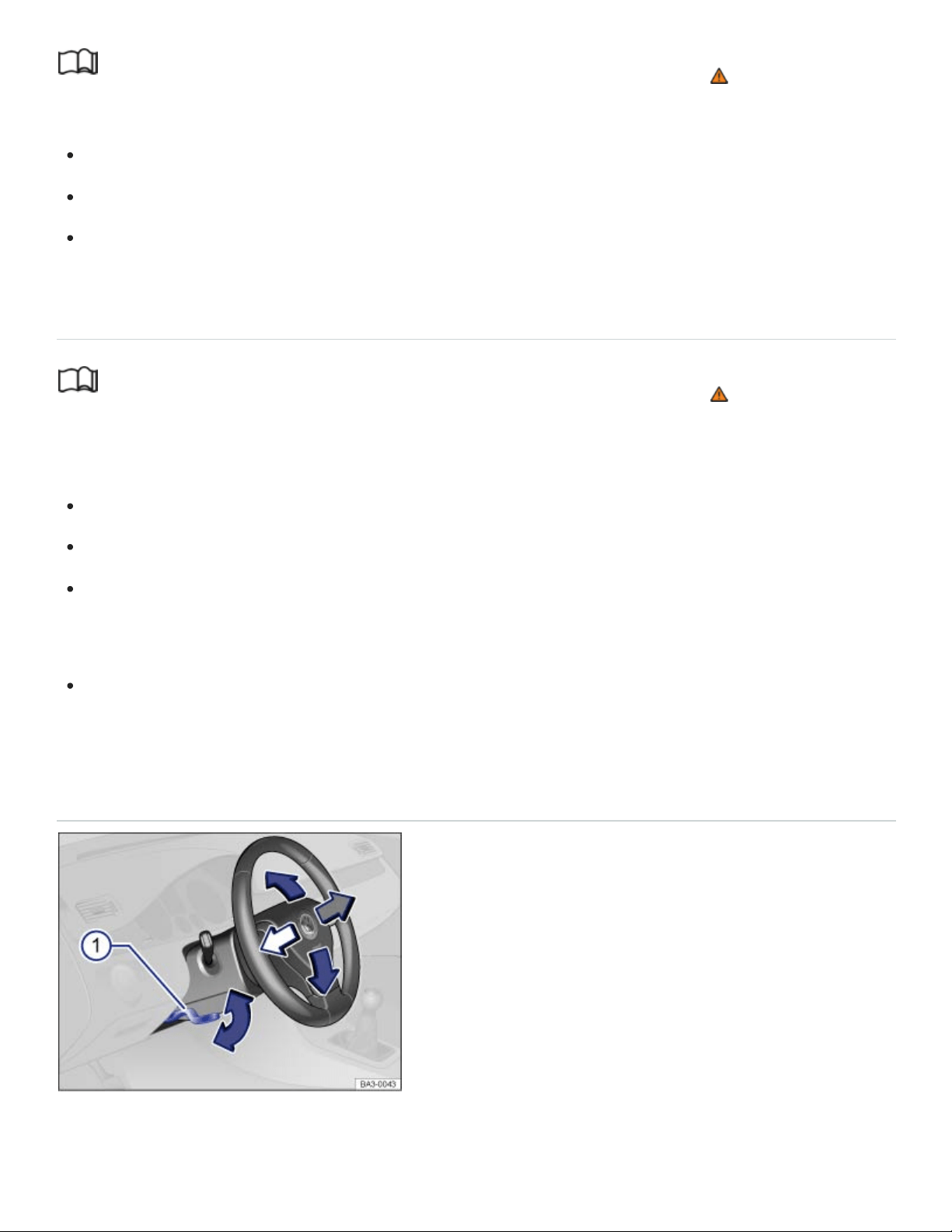
Read and follow the introductory information and safety information first⇒ Introduction to the
subject
The vehicle must be within range of the device to be operated.
With ignition turned on or engine running, press the appropriate button on the roof console.
Do not press the button for longer than 2 seconds, or else the button will switch into the program‐
ming mode.
Tips and troubleshooting
Read and follow the introductory information and safety information first⇒ Introduction to the
subject
If the HomeLink Universal Transmitter does not work
Try different distances and angles to the receiver.
OR: Reprogram the garage door opener.
OR: The garage door or electrical drive is not compatible and must be replaced.
The HomeLink Universal Transmitter cannot be programmed
Hold the hand-held remote control in another position while pointing it towards the steering wheel.
Steering wheel
Manually adjusting the steering wheel position
Fig.71Manual adjustment for the steering wheel position.
®
®
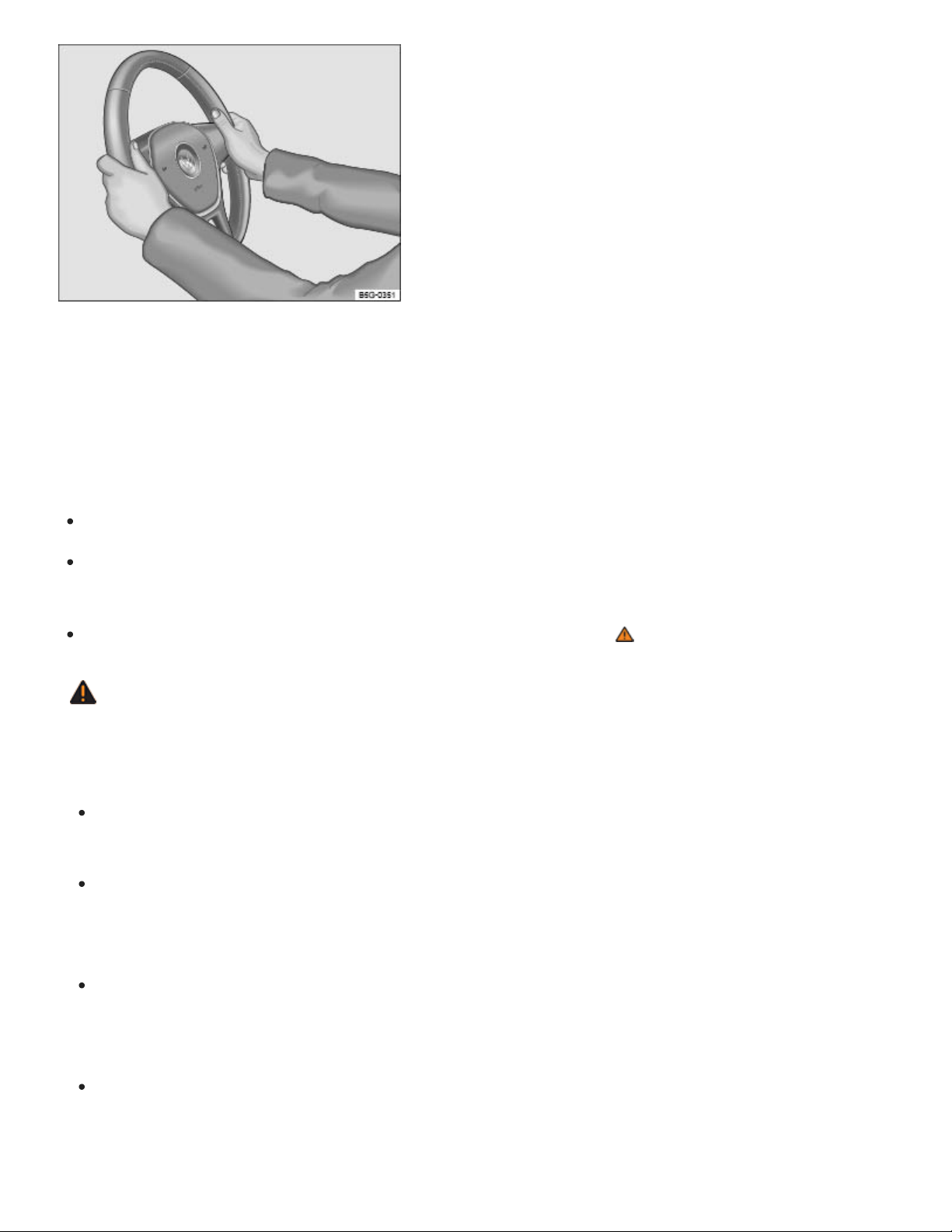
Fig.72Steering wheel: 9 o'clock and 3 o'clock positions.
The steering wheel can be adjusted up and down (blue arrows) or forward and back (white and gray
arrows) ⇒Fig.71 .
Adjust the steering wheel only when the vehicle is not moving.
Push down on the lever ⇒Fig.71① .
Adjust the steering wheel so that it can be held with hands at the 9o'clock and 3o'clock positions
on the outside of the steering wheel rim and with the arms slightly bent at the elbow ⇒Fig.72 .
Pull the lever up firmly until it is flush with the steering column ⇒ .
WARNING
Improper use of the steering wheel adjustment feature can result in serious personal injury and
even death.
Always pull the lever ⇒Fig.71① firmly upward after adjusting the steering wheel so that the
steering wheel does not change position suddenly while the vehicle is moving.
Never adjust the steering wheel while the vehicle is moving. If you find that you need to adjust
the steering wheel while driving, stop the vehicle in a safe place and make the proper
adjustment.
Never adjust the steering wheel so that it points toward your face. Always make sure that the
steering wheel points toward your chest. Otherwise, the airbag system cannot protect you
properly in the event of a crash.
Always hold the steering wheel on the outside of the steering wheel rim with your hands at the
9o'clock and 3o'clock positions ⇒Fig.72 to help reduce the risk of serious personal injury if
the driver's airbag inflates.

Never hold the steering wheel at the 12o'clock position or with your hands anywhere inside
the steering wheel or on the steering wheel hub. Holding the steering wheel the wrong way in‐
creases the risk of severe injury to the arms, hands, and head if the driver airbag deploys.
Seats and head restraints
Driver and front passenger seats
Introduction to the subject
In this chapter you will find information on the following subjects:
⇒Manual controls on the driver and front passenger seats
⇒Electrical controls on the driver and front passenger seats
WARNING
Always adjust seat, safety belts, and head restraints properly before driving and make sure that
all passengers are properly restrained.
Push the passenger seat as far back as possible. Always be sure that there are at least
10inches (25cm) between the front passenger's breastbone and the instrument panel.
Always adjust the driver's seat and the steering wheel so that there are at least 10inches
(25cm) between your breastbone and the steering wheel.
Adjust the driver's seat so that you can easily push the pedals all the way to the floor while
keeping your knee(s) slightly bent.
If these requirements cannot be met for physical reasons, contact an authorized Volkswagen
dealer or an authorized Volkswagen Service Facility to see whether adaptive equipment is
available.
Always hold the steering wheel on the outside of the steering wheel rim with your hands at the
9o'clock and 3o'clock positions to help reduce the risk of personal injury if the driver's airbag
inflates.
Never hold the steering wheel at the 12o'clock position or with your hands at other places in‐
side the steering wheel rim or on the steering wheel hub. Holding the steering wheel the wrong
way can cause serious injuries to the hands, arms, and head if the driver's airbag inflates.

Pointing the steering wheel toward your face decreases the ability of the driver's airbag to help
protect you in a collision.
Never drive with backrests reclined or tilted back farther than necessary to drive comfortably.
The farther back the backrests are tilted, the greater the risk of injury caused by incorrect posi‐
tioning of the safety belts and improper seating position.
Never drive with the front seat passenger backrest tilted forward. If the front airbag deploys,
the front backrest can be forced backward and injure passengers on the rear seat.
Sit as far back as possible from the steering wheel and the instrument panel.
Always sit upright with your back against the backrest with the front seats properly adjusted.
Never lean against or place any part of your body too close to the area where the airbags are
located.
Rear seat passengers who are not properly seated and restrained are more likely to be seri‐
ously injured in a crash.
WARNING
Improper adjustment of the seats can cause accidents and severe injuries.
Never adjust the seats while the vehicle is moving. Your seat may move unexpectedly and you
could lose control of the vehicle. In addition, you will not be in the correct seating position while
adjusting the seats.
Adjust the front seat height, angle and longitudinal direction only if the seat adjustment area is
clear.
The adjustment of the front seats must not be restricted by things in the footwell in front or be‐
hind the seats.
WARNING
Improper use of seat covers can lead to an accidental activation of the electrical seat controls
and can cause the front seats to move unexpectedly while driving. You could lose control of the
vehicle, crash, and seriously injure yourself and others. Furthermore, the electrical components
of the front seats could be damaged.
Never attach seat covers to the electrical seat controls.
Never put seat covers or replacement upholstery on the front seats that have not been ap‐
proved by Volkswagen for your specific vehicle.
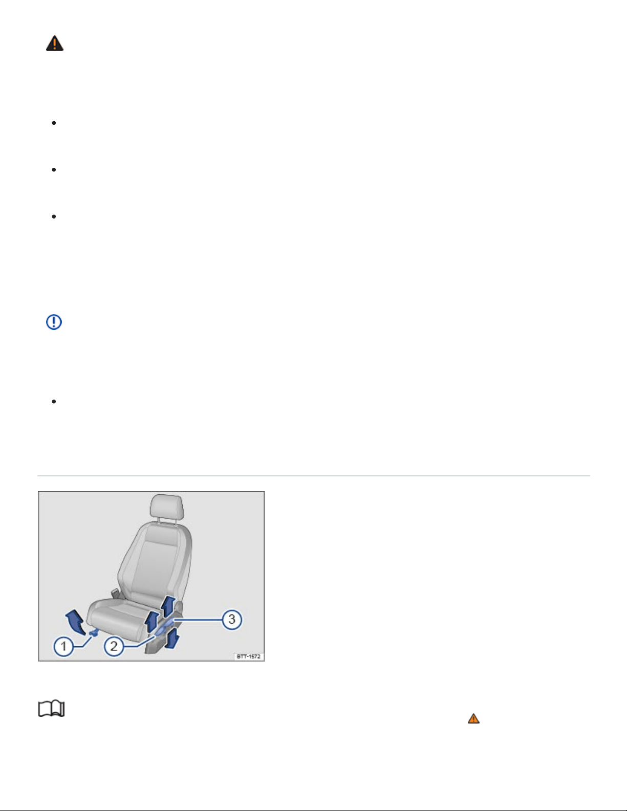
WARNING
Some kinds of cigarette lighters can be lit unintentionally, or crushed causing a fire that can result
in serious burns and vehicle damage.
Always make sure that there are no lighters in the seat tracks or near other moving parts be‐
fore adjusting the seats.
Before closing a storage compartment, always make sure that no cigarette lighter can be acti‐
vated, crushed, or otherwise damaged.
Never leave a cigarette lighter in a storage compartment, on the instrument panel, or in other
places in the vehicle. Heat buildup in the passenger and luggage compartment of a parked ve‐
hicle can result in temperatures in the vehicle that are much higher than the outside tempera‐
tures, particularly in summer. High temperatures could cause the cigarette lighter to catch fire.
NOTE
Sharp-edged objects and items on clothing and belts (such as belt clips, mobile phone cases,
zippers, rivets, and rhinestones) can damage upholstery material and fabric trim.
To help prevent damage, do not let such items come into direct contact with the upholstery and
fabric trim.
Manual controls on the driver and front passenger seats
Fig.73Driver seat: Manual seat adjustment controls.
Read and follow the introductory information and safety information first⇒ Introduction to the
subject

The illustration and information in this section describes all possible seat controls. The number of
controls may vary depending on the version of the seat.
The controls on the front passenger seat either mirror those on the driver seat or there may be differ‐
ent combinations of manual and electrical controls, depending on vehicle equipment.
There may be manual and electrical controls on the same seat.
Key to ⇒Fig.73 :
Move the front seat forward or back. Pull the lever up and move the front seat. The front seat
must lock in place after the lever is released!
Adjust the backrest angle. Pull the lever up and move the seat backrest. The seat backrest must
lock in place after the lever is released!
Adjust the seat height. Move the lever several times up or down.
Electrical controls on the driver and front passenger seats
Fig.74Driver seat: Electrical controls to move the seat backward or forward, and adjust seat cushion
height and backrest angle (if equipped).
Fig.75Lumbar support control (if equipped).
Read and follow the introductory information and safety information first⇒ Introduction to the
subject

Ⓐ
Ⓑ
Ⓒ
Ⓓ
①
②
If your vehicle is equipped with electrical controls for the front seats, the controls on the front passen‐
ger seat either mirror those on the driver seat or there may be different combinations of electrical and
manual controls.
There may be manual and electrical controls on the same seat.
Electrical seat controls
Press the switch in the direction of the arrow ⇒Fig.74 :
Slide the seat forward or back.
Adjust the seat cushion angle.
Raise or lower the seat cushion.
Adjust the backrest angle.
Lumbar support controls
Press the switch in the corresponding area ⇒Fig.75 :
Adjust the curve of the lumbar support (forward).
Adjust the curve of the lumbar support (back).
WARNING
Improper use of electrical seat controls can cause serious personal injuries.
The front seats in your vehicle can be electrically adjusted even when the vehicle key has
been removed from the ignition or, on a vehicle with Keyless Access, even if there is no key in
the vehicle.
Never leave children and persons who need help in the vehicle alone because the unsuper‐
vised use of the electric seat adjustments can result in serious personal injury.
Always make sure that no one is in the way while the front seats are being adjusted, or while
calling up the stored memory settings for the front seats. In an emergency, stop automatic seat
adjustment by pressing a seat adjustment switch.
NOTE
To help prevent damage to electrical parts in the seat, do not kneel on the front seats or apply
concentrated pressure to a small area of the seat or backrest.

If the vehicle battery is too weak, the electrical seat adjustment controls may not work.
When entering and exiting the vehicle, be careful not to come into contact with any switches that
could change the seat adjustment.
Rear seats
Introduction to the subject
In this chapter you will find information on the following subjects:
⇒Adjusting the second row seats
⇒Folding the second row of seats forward and back into place
⇒Folding the third row of seats forward and back into place
WARNING
Improper adjustment of the rear seats can cause accidents and severe injuries.
Adjust the rear seats only when the vehicle is stopped, since the seat could otherwise move
unexpectedly when the vehicle is moving.
Adjust the rear seats only if no one is in the way.
Always guide the backrest down by hand and never let it fall into place on its own.
WARNING
Some kinds of cigarette lighters can be lit unintentionally, or crushed causing a fire that can result
in serious burns and vehicle damage.
Always make sure that there are no lighters in the seat tracks or near other moving parts be‐
fore adjusting the seats.
Before closing a storage compartment, always make sure that no cigarette lighter can be acti‐
vated, crushed, or otherwise damaged.
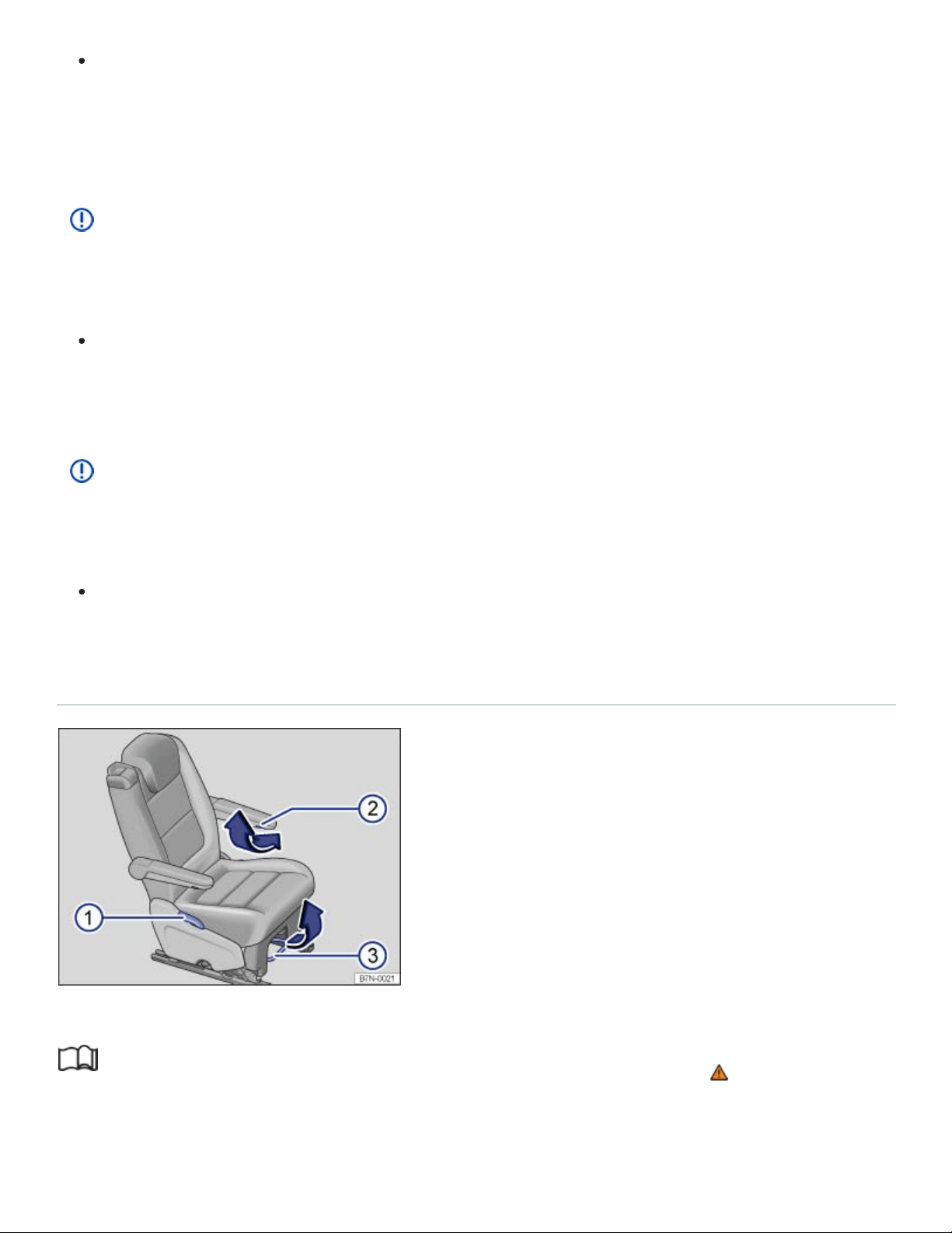
Never leave a cigarette lighter in a storage compartment, on the instrument panel, or in other
places in the vehicle. Heat buildup in the passenger and luggage compartment of a parked ve‐
hicle can result in temperatures in the vehicle that are much higher than the outside tempera‐
tures, particularly in summer. High temperatures could cause the cigarette lighter to catch fire.
NOTE
Items behind or under the second row seats could be damaged or cause damage when the seats
are adjusted forward or backward.
If a second row seat is in a forward position, items can get into the area between the seat and
the floor. Before you slide the seat back again, make sure that the area behind the seat is
clear of objects.
NOTE
Sharp-edged objects and items on clothing and belts (such as belt clips, mobile phone cases,
zippers, rivets, and rhinestones) can damage upholstery material and fabric trim.
To help prevent damage, do not let such items come into direct contact with the upholstery and
fabric trim.
Adjusting the second row seats
Fig.76In the second row: Adjusting the seats.
Read and follow the introductory information and safety information first⇒ Introduction to the
subject

Your vehicle may be equipped with two seats in the second row. Each seat can be adjusted
separately.
Key to ⇒Fig.76 :
Pull the lever to move the seat backrest to the desired position. Release the lever and lock the rear
backrest by gently tilting it forward or backward.
Only in vehicles with 6 seats: Turn the handwheel under the armrest to adjust the position of the
armrest.
Pull the lever to move the seat forward or backward. Release the lever and lock the rear seat by gen‐
tly sliding it forward or backward.
WARNING
Improper adjustment of the rear seat can cause accidents and severe injuries.
Adjust the rear seat only when the vehicle is stopped, since the seat could otherwise move un‐
expectedly when the vehicle is moving.
Adjust the rear seat only if no one is in the way.
Always guide the backrest down by hand and never let it fall into place on its own.
NOTE
Items in the luggage compartment could be damaged or cause damage when the rear seat is ad‐
justed forward and backward.
If the rear seat is in a forward position, items can get into the area between the seat and the
luggage compartment floor. When you slide the rear seat back again, make sure that the area
behind the seat is clear of objects.
Folding the second row of seats forward and back into place
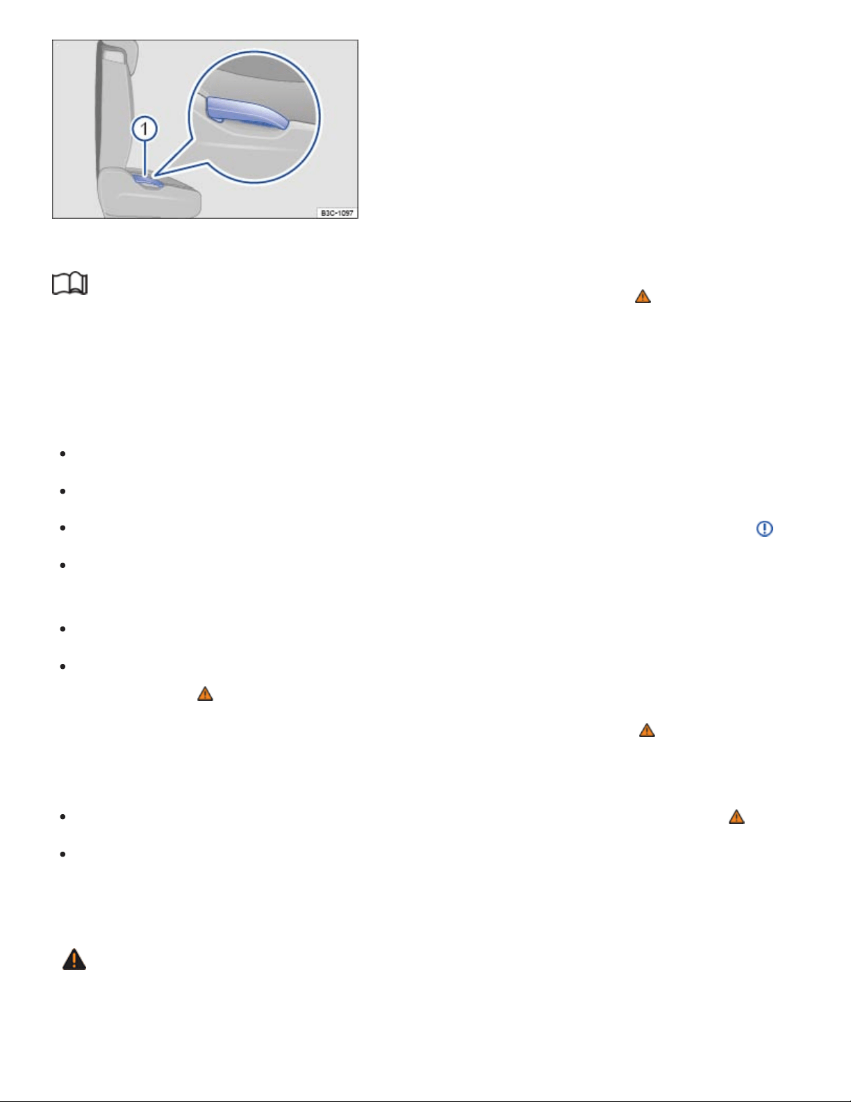
Fig.77In the second row: Lever to release the second row seat backrest.
Read and follow the introductory information and safety information first⇒ Introduction to the
subject
Each backrest in the second row may be folded forward to extend the luggage compartment.
Folding the second row seats forward
Move the driver and passenger seats forward, if necessary.
Fold up the second row armrests.
Remove objects from the second row seat footwell and from behind the second row seats ⇒ .
Pull the lever ⇒Fig.76③ on the second row seat and move it as far back as it will go ⇒Adjusting
the second row seats .
Push the second row head restraint as far down as it will go ⇒Head restraints .
Pull up the lever completely ⇒Fig.77① and fold the second row seat backrest forward until it
locks in place ⇒ .
When the backrest is folded forward, no person or child may ride on that seat ⇒ .
Folding the second row seat backrest back into place
Pull up the lever and push the second row seat backrest back into the upright position ⇒ .
Pull and push on the backrest to ensure that the seat is securely latched into place. The second
row seat backrest must be securely latched into place for the safety belts on the second row seats
to provide optimal protection.
WARNING
Improper folding and improper latching of the second row seat backrests can cause serious per‐
sonal injury.

Always make sure there are no people or animals in the area around the second row seat
backrest when folding it forward.
Never fold a second row seat backrest forward or back when the vehicle is moving.
When folding the backrest into the upright position, be careful not to catch or damage the
safety belt in the backrest hinges.
Always keep hands, fingers, feet and other body parts out of the way of the seat hinges and
the seat locking mechanism when folding the backrest forward and back.
Each second row seat backrest must be securely latched in the upright position so that the
safety belts on the rear seats can provide protection. This is particularly the case for the mid‐
dle seat on the second row seat bench.
Floor mats and other objects can get caught in the backrest hinges. This can cause the back‐
rest to incorrectly latch when folded into the upright position.
A red indicator on the release lever ⇒Fig.78 shows that the backrest is not securely latched
in the upright position. The red indicator is not visible when the backrest is securely latched.
If a seat is used with an unsecured backrest, the passenger will move forward together with
the rear seat backrest during sudden braking, driving maneuvers, or in a collision.
No one, including children, may ride on the second row seats if the second row seat backrest
is folded down or not correctly latched.
NOTE
Objects in the footwell or under the second row seats may be damaged when the backrest is
folded forward and back. Always remove objects before folding the backrest forward.
NOTE
Before folding a second row seat forward, move the front seat so that the second row head re‐
straint does not touch the front seat backrest.
Folding the third row of seats forward and back into place
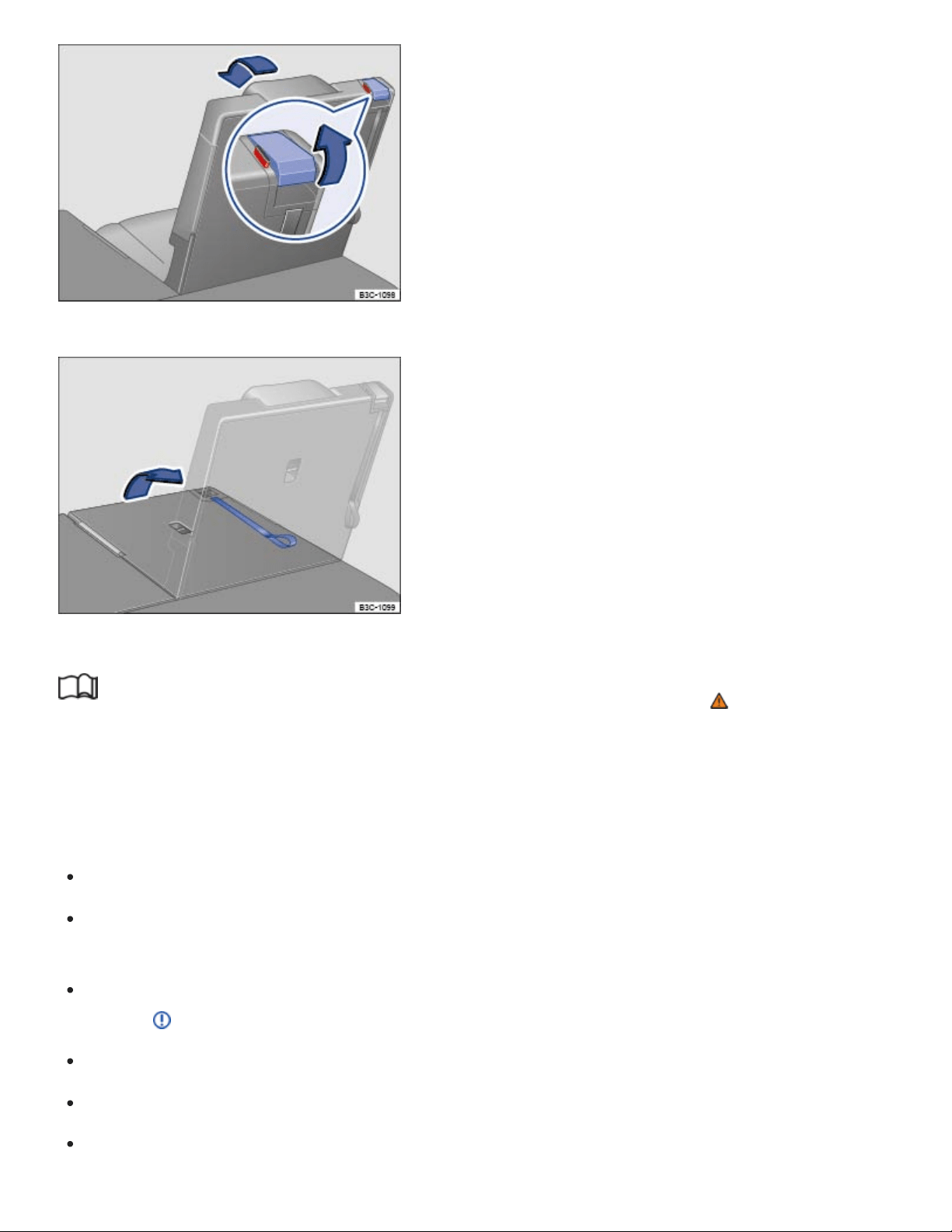
Fig.78In the third row: Lever to release the third row seat backrest.
Fig.79In the third row: Strap to raise the third row seat backrest.
Read and follow the introductory information and safety information first⇒ Introduction to the
subject
Each backrest in the third row may be folded forward to extend the luggage compartment.
Folding the third row seat forward
Push the head restraint as far down as it will go ⇒Head restraints
Release the safety belt from the belt buckle and slide it into the safety clip to help reduce the risk
of damaging the safety belt.
Remove objects from the third row seat footwell, from underneath, and from behind the third row
seats ⇒ .
Move the second row seats forward.
Open the trunk lid ⇒Trunk lid .
Pull the release lever ⇒Fig.78 completely upwards to unlock the third row seat backrest.

Push the backrest down with your hand into the horizontal position. When the backrest is folded
forward, no person or child may ride on that seat ⇒ .
Close the trunk lid.
Raising the third row seat backrests into place
Open the trunk lid ⇒Trunk lid .
Pull the loop on the backrest ⇒Fig.79 to fold the backrest into place. OR: From inside the vehi‐
cle, push the lever up and, at the same time, push the backrest into place with your hand.
When the backrest is securely latched, the red indicator on the release lever ⇒Fig.78 will no
longer be visible.
Pull and push the backrest to ensure that it is securely latched in the upright position ⇒ .
Attach the loop to the backrest using the Velcro on the loop. Do not attach the loop too tightly to
the backrest, as this may cause the backrest to not securely latched.
Close the trunk lid.
WARNING
Improper folding and improper latching of the third row seat backrests can cause serious per‐
sonal injury.
Never fold a third row seat backrest forward or back when the vehicle is moving.
When folding the backrest into the upright position, be careful not to catch or damage the
safety belt in the backrest hinges.
Always keep hands, fingers, feet and other body parts out of the way of the seat hinges and
the seat locking mechanism when folding the backrest forward and back.
Floor mats and other objects can get caught in the backrest hinges. This can cause the back‐
rest to latch incorrectly when folded into the upright position.
If the loop on the backrest ⇒Fig.79 is attached too tightly to the backrest, the backrest may
not securely latch. Detach the loop and try to latch the backrest again.
The backrest must always be securely latched in the upright position so that the safety belts in
the third row can offer optimum protection. If a seat is occupied while the backrest is not se‐
curely latched in the upright position, the vehicle occupant will move with the backrest during a
sudden braking maneuver or in an accident.
®

A red indicator on the release lever ⇒Fig.78 shows that the backrest is not securely latched
in the upright position. The red indicator will not be visible when the backrest is securely
latched.
Do not let passengers or children occupy a third row seat when the backrest is folded forward.
NOTE
Objects on a seat cushion in the third row may be damaged when the backrest is folded for‐
ward. Always remove objects before folding the backrest forward.
Head restraints
Introduction to the subject
In this chapter you will find information on the following subjects:
⇒Adjusting the front head restraints
⇒Removing and reinstalling the front head restraints
Proper head restraint adjustment
Adjust head restraints so that the upper edge of the head restraint is at least at eye level or higher.
Position the back of the head as close as possible to the head restraint.
Adjusting the head restraint for shorter people
Push the head restraint down as far as it will go, even if this means the person's head is still below
the top edge of the head restraint. A small gap may remain between the head restraint and the back‐
rest when the head restraint is all the way down.
Adjusting the head restraint for taller people
Pull the head restraint up as far as it will go.
WARNING
Driving without head restraints or with improperly adjusted head restraints increases the risk of
serious injuries in a collision.
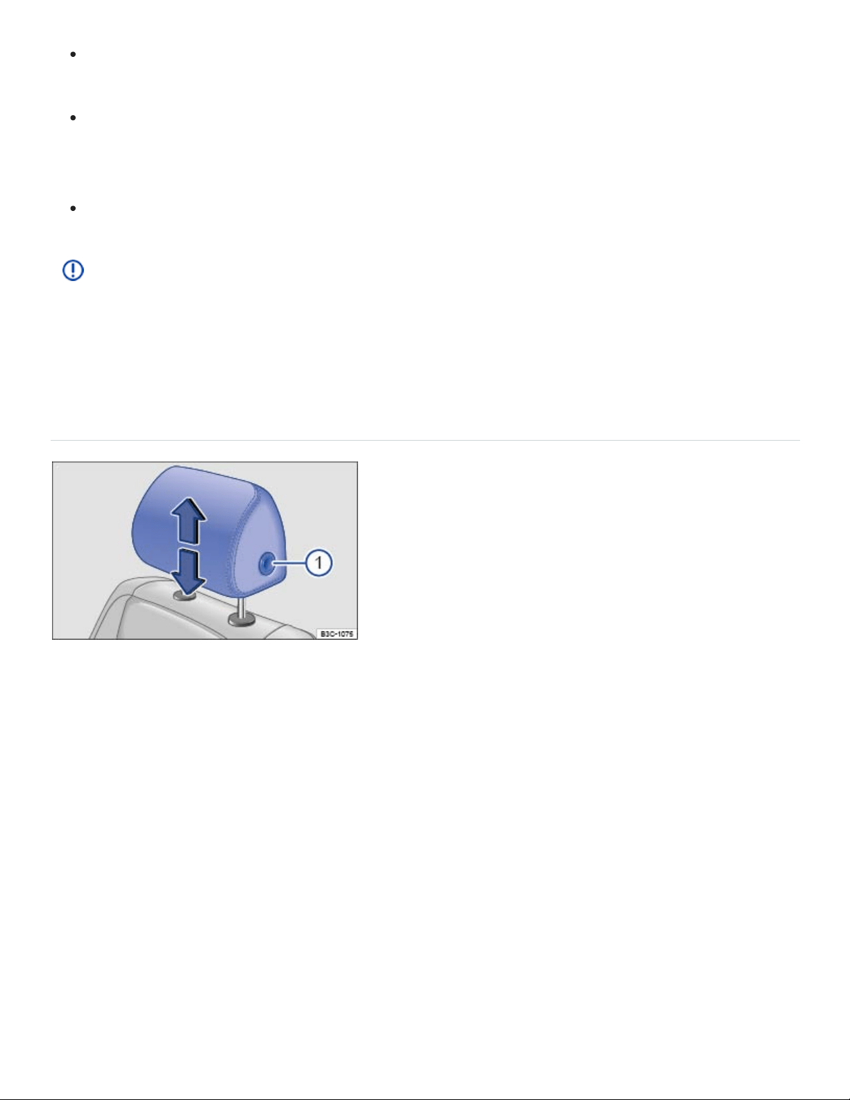
Never drive or let a passenger ride in the vehicle until the head restraints are installed and
properly adjusted to help minimize the risk of neck injury in a crash.
Each head restraint must be adjusted according to the occupants' size so that the upper edge
is even with the top of the person's head, but no lower than eye level. Always sit so that the
back of your head is as close as possible to the head restraint.
Never adjust head restraint while driving.
NOTE
When removing or reinstalling the head restraint, make sure that the head restraint does not
strike the headliner or other parts of the vehicle. The headliner or other parts of the vehicle could
otherwise be damaged.
Adjusting the front head restraints
Fig.80Adjusting the front head restraints.
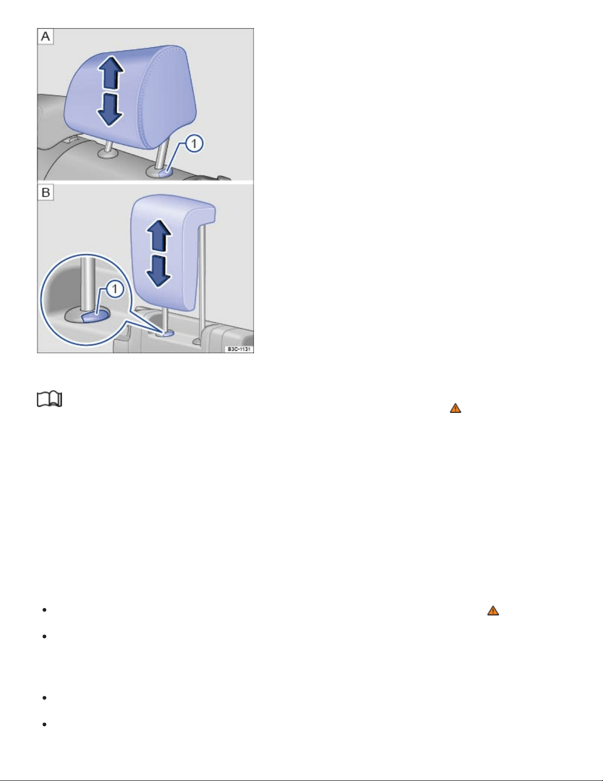
Fig.81Adjusting the rear head restraints: second row, third row.
Read and follow the introductory information and safety information first⇒ Introduction to the
subject
All seats are equipped with head restraints.
There are notches in the head restraint guide rods so that the head restraint can lock into place in dif‐
ferent positions. Only properly installed head restraints can lock into place at the adjustment range
notches. In order to help prevent inadvertent removal of the head restraints after installation, there are
stops at the top and bottom of the adjustment range.
Adjusting the height of front head restraints
While pressing the button ⇒Fig.80① , pull the head restraint up or push it down ⇒ .
The head restraint must lock securely in position.
Adjusting the height of the rear head restraints
Push the head restraint up.
To lower the headrest, first push the headrest down as far as it will go. Then push the button
⇒Fig.81① and push the head restraint down completely.
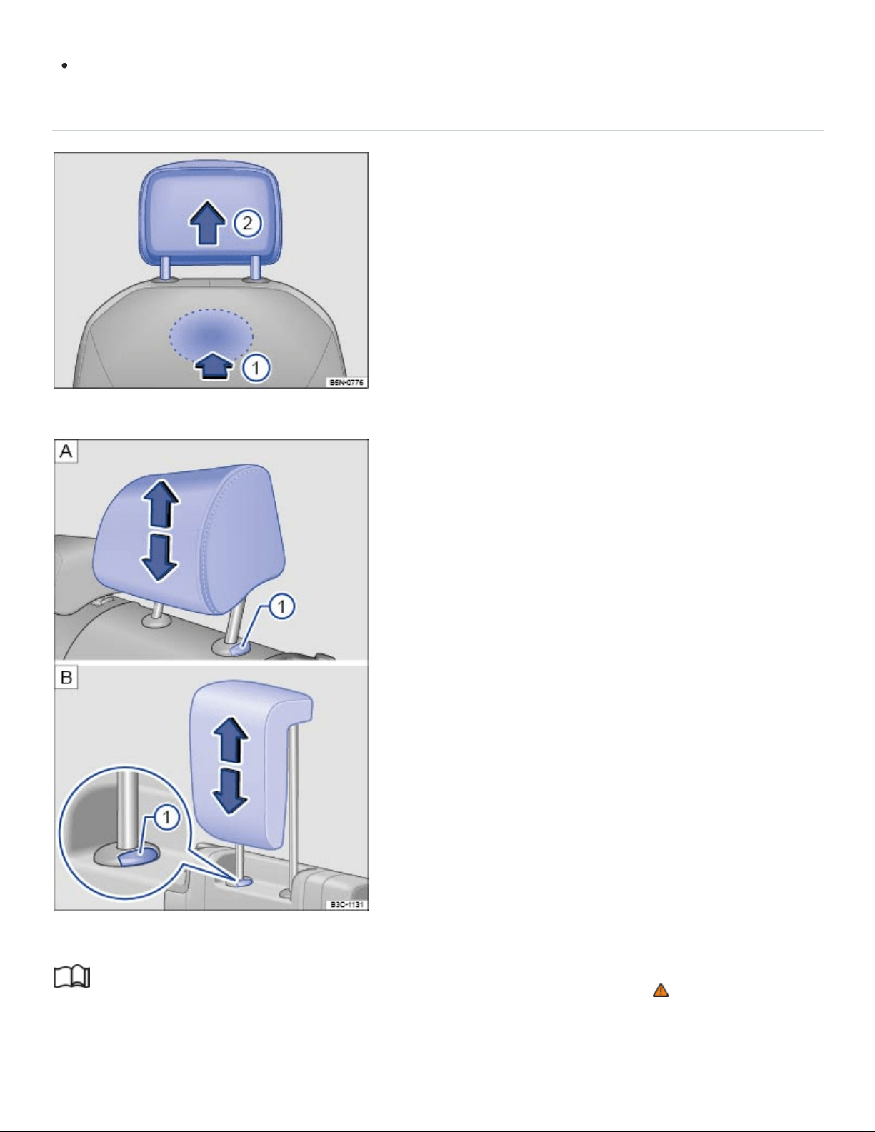
The head restraint must lock securely in position.
Removing and reinstalling the front head restraints
Fig.82Removing the front head restraints.
Fig.83Removing the rear head restraints: second row, third row.
Read and follow the introductory information and safety information first⇒ Introduction to the
subject

All seats are equipped with head restraints. The rear center head restraint is designed only for the
center seat on the rear bench. Therefore, only install the center head restraint in the center position.
Removing the front head restraints
Sit in the back seat behind the head restraint you want to remove.
Push the head restraint all the way down. Recline the backrest with the head restraint so that
there is enough overhead clearance to remove it.
On the back of the backrest, locate the release button under the seat cover and keep it pressed
down ⇒Fig.82 ①.
While pressing button ①, pull the head restraint out completely.
Reinstalling the front head restraints
Position the head restraint properly over the head restraint guides of the respective seat backrest
and insert the head restraint rods into the guides.
Push the head restraint down.
Adjust the head restraint according to the occupant's size ⇒Adjusting the front head restraints .
Removing the rear head restraints (second and third row)
If necessary, unlock the backrest and fold it forward so that the head restraint can be removed
⇒Folding the third row of seats forward and back into place .
Pull the head restraint all the way up ⇒ .
Push button ⇒Fig.83① in and hold it.
Pull out the head restraint completely.
Reinstalling the rear head restraints (second and third row)
If necessary, unlock the backrest of the third row seat bench and fold it forward ⇒Folding the third
row of seats forward and back into place .
Position head restraint rods properly over the head restraint guides of the respective seat backrest
and insert the head restraint rod into the guides.
Push the head restraint down while pressing button⇒Fig.83① .
Fold the backrest of the third row seat bench back so that it locks securely.
Adjust the head restraint according to the occupant's size.

NOTE
Before folding the third row backrest forward, adjust the second row seats so that the third row
head restraints or backrest cushion will not touch the second row seats.
Seat functions
Introduction to the subject
In this chapter you will find information on the following subjects:
⇒Memory seats
⇒Center armrests
⇒Entry assistance for the third row seats
WARNING
Improper use of seat adjustment controls can cause severe personal injuries.
Always sit properly at all times before starting to drive and while the vehicle is moving. Make
sure all passengers, especially children, are properly seated whenever the vehicle is moving.
Keep hands, fingers, feet and other body parts away from moving parts and adjustment areas
of the seats.
Certain settings are automatically saved by the driver personalization feature ⇒Driver
Personalization .
Memory seats
Fig.84On the driver seat: Memory buttons.

Read and follow the introductory information and safety information first⇒ Introduction to the
subject
Your vehicle may be equipped with seat memory functions for the driver seat and the outside mirrors.
Memory buttons
Each memory button can be assigned with individual settings for the driver seat and the outside
mirrors.
Storing driver seat settings and forward driving settings for outside mirrors
Set the electronic parking brake.
Turn on the ignition.
Shift the transmission into Neutral (N).
Adjust the driver seat and outside mirrors.
Press the button for longer than a second ⇒Fig.84 .
Within about 10 seconds, press the desired memory button. A chime signal will confirm the saved
setting.
Storing reverse driving settings for the passenger side outside mirror
Set the electronic parking brake.
Shift the transmission into Neutral (N).
Turn on the ignition.
Press the desired memory button.
Shift the transmission into Reverse (R).
Adjust the passenger side outside mirror.
The mirror position is automatically saved and assigned to the remote control vehicle key which
was used to unlock the vehicle.
Recalling stored memory settings
When the ignition is switched off and the driver door is open, press the corresponding memory
button. Pressing the memory button again cancels the movement. If the ignition has been
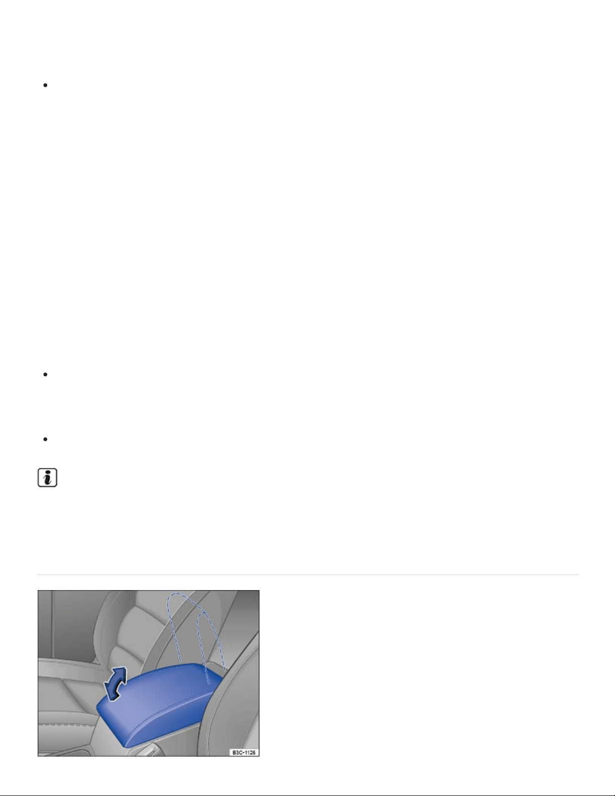
switched off for more than about 10 minutes, then the stored memory settings can no longer be
recalled.
OR: When the ignition is on, press the memory button and hold until the seats and mirrors are
fully adjusted to the saved position.
The passenger mirror moves back from the reverse driving setting when the vehicle moves forward
faster than about 10mph (15km/h) or the adjusting knob is moved from R to another position
⇒Mirrors .
Driver personalization
You can save your individual seat settings in the Driver Personalization.
The memory seat settings will be saved in the user profile once the ignition is switched off and the ve‐
hicle is locked.
When the vehicle is unlocked and the driver door is opened, the driver seat and outside mirrors will
automatically move to the set position.
Vehicle is stopped or moving slower than 3 mph (5 km/h): The driver seat and outside mirrors
move to the new settings. You can cancel the movement by pressing the relevant function key in
the Infotainment system or one of the buttons on the driver seat.
Vehicle is moving faster than 3 mph (5 km/h): The driver seat does not move to the new settings.
All other settings in the user profile will change.
If the driver door is not opened within about 10 minutes after the vehicles has been unlocked, the
driver seat and outside mirrors will not automatically move.
Center armrests
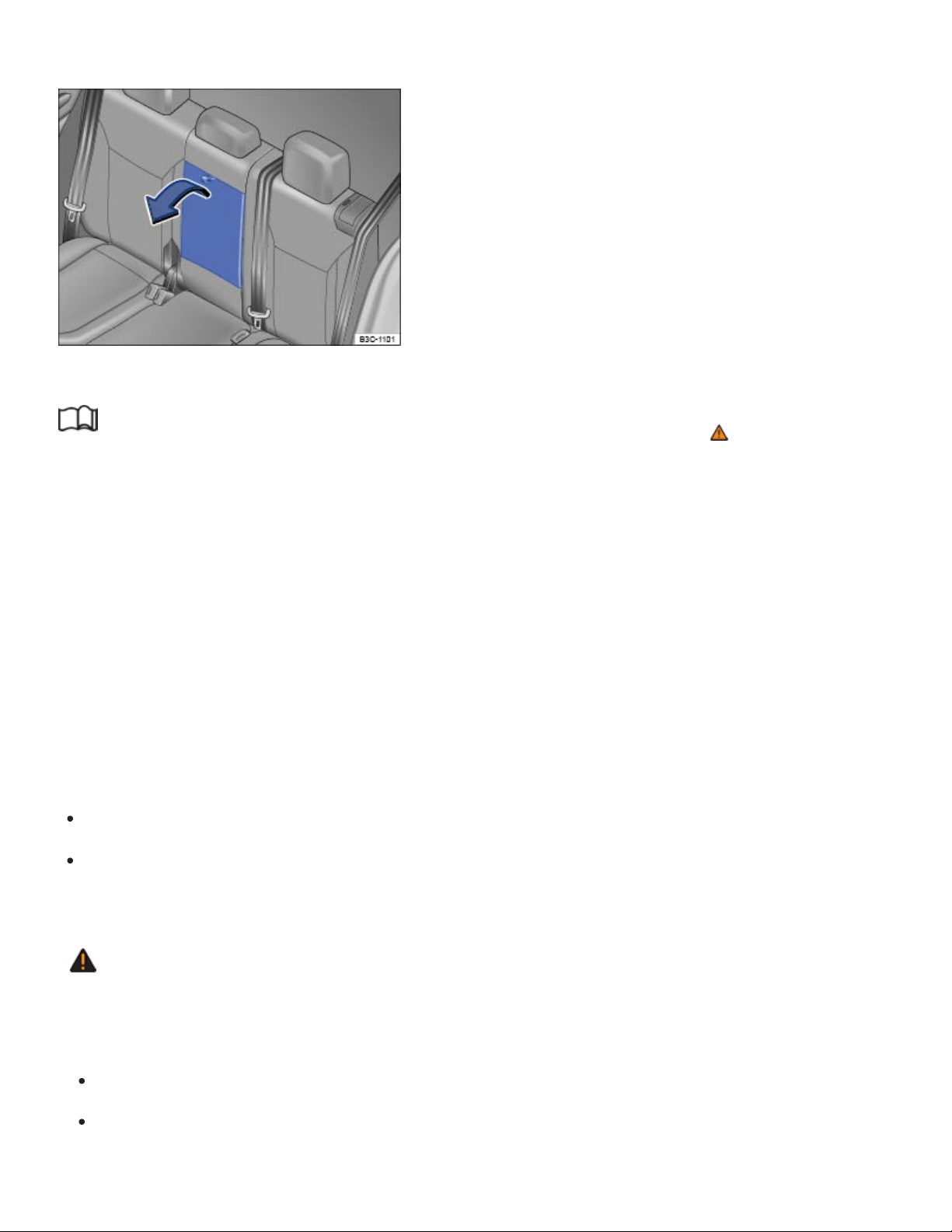
Fig.85Front center armrest
Fig.86Rear center armrest
Read and follow the introductory information and safety information first⇒ Introduction to the
subject
For vehicles with 6 seats: The armrests on the second row seats can be adjusted ⇒Adjusting the
second row seats .
Front center armrest
The front center armrest includes a storage compartment ⇒Storage compartment between the front
seats
Rear center armrest (vehicles with 7 seats)
There may be a fold-down armrest in the backrest of the second row seat bench ⇒Fig.86 .
To fold down, pull the loop in the direction of the arrow ⇒Fig.86 -
To fold up, push the center armrest up as far as it will go.
A person cannot sit on the rear center seating position if the center armrest is folded down.
WARNING
When completely open or improperly adjusted, the center armrest can restrict the driver's arm
movement and cause crashes and serious personal injury.
Always keep storage compartments closed while driving.
Never let a passenger, especially a child, ride on the center armrest. Improper seating position
can increase the risk of serious personal injury in a crash.

Never put hot drinks or other liquids in the cup holders without secure lids on the beverage
containers. Liquids can spill when the vehicle is moving as well as during braking or other sud‐
den maneuvers.
Entry assistance for the third row seats
Fig.87In the second row: The entry assistance lever.
Fig.88Behind the second row: The emergency loop for exiting the third row seats.
Read and follow the introductory information and safety information first⇒ Introduction to the
subject
The seats in the second row can be folded forward to make entering and exiting the third row easier.
Folding the second row seat backrests forward
Remove any objects from the second row seat footwell ⇒ .
Push the head restraint down as far as it will go ⇒Head restraints .
Pull the lever in either direction ⇒Fig.87 . A red indicator next to the lever will pop up to indicate
that the seat is unlocked.

Pull the seat forward. The entire seat will tilt forward. The folded seat can be also be push
forward.
Carefully enter or exit the third row ⇒ .
Folding back the second row seat backrests
Push the seat back completely.
Pull the lever ⇒Fig.87 up and fold the backrest into the upright position ⇒ .
The backrest must be securely latched in the upright position. If the red indicator is still visible, the
backrest is not securely latched!
Emergency exit for the third row
If the lever ⇒Fig.87 does not function, for example after an accident, an occupant in the third row
can fold the second row seats forward to make exiting the third row easier ⇒ .
Pull the red loop ⇒Fig.88 backwards and fold the backrest forward. The complete backrest will
fold forward.
WARNING
Improper folding and improper latching of the second row seat backrests can cause serious per‐
sonal injury.
Never fold a second row seat backrest forward or back when the vehicle is moving.
When folding the backrest into the upright position, be careful not to catch or damage the
safety belt in the backrest hinges.
Always keep hands, fingers, feet and other body parts out of the way of the seat hinges and
the seat locking mechanism when folding the backrest forward and back.
Floor mats and other objects can get caught in the backrest hinges. This can cause the sec‐
ond row seat backrest to incorrectly latch when folded back into the upright position.
When folded back into place, the second row seat backrest must be securely latched in the
upright position. If the red indicator is still visible, the backrest is not securely latched. An im‐
properly latched front passenger backrest can suddenly move and cause serious personal
injury.
Do not let passengers or children occupy a second row seat when the backrest is folded
forward.

Do not use the folded second row seat to lean on or to support yourself while entering or exit‐
ing the third row.
WARNING
If child restraints are installed on all seats in the second row, someone in the third row may not be
able to fold the second row seat backrests forward. Therefore passengers in the third row may
not be able to exit the vehicle in an emergency without help.
Never install child restraints on all seats in the second row if there are passengers in the third
row.
NOTE
Before folding the second row seat backrests forward or back into place, make sure that the
headrest will not hit the front passenger seat.
NOTE
Objects in the footwell or under the second row seats may be damaged when the backrest is
folded forward. Always remove objects before folding the backrest forward.
Objects under the second row seats may be damaged when the seats are folded back.
Remove items before folding the seats back.
Objects or dirt in the seat tracks may damage the seats when the seats are folded forward.
Carefully clean the tracks before folded the seats forward.
Lights
Turn signals
Switching turn signals on and off
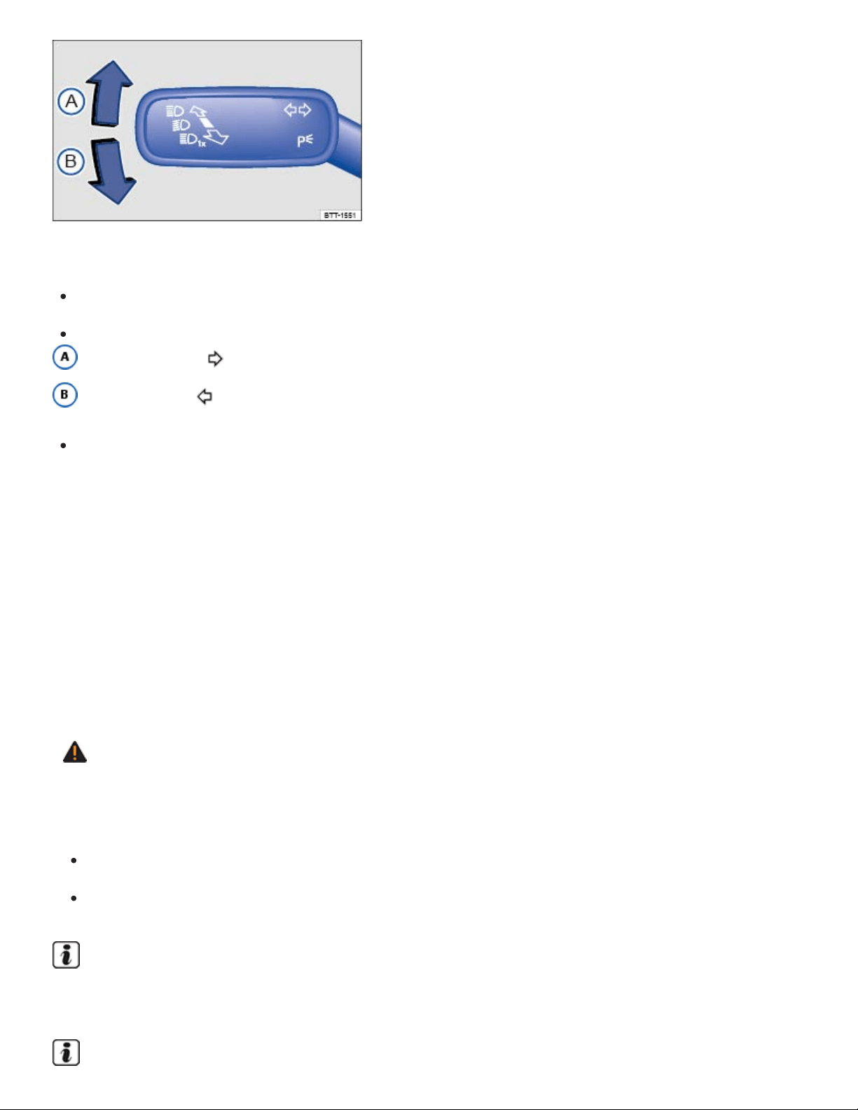
Fig.89To the left of the steering wheel: Turn signal and high beam lever.
Switch on the ignition.
Move the turn signal and high beam lever ⇒Fig.89 to position:
Right turn signal .
Left turn signal .
Move the lever back to the home position to switch the turn signal off.
If you do not hear an acoustic sound when the turn signal is switched on, contact an authorized
Volkswagen dealer or an authorized Volkswagen Service Facility.
3-blink turn signal (convenience indicating)
Move the turn signal lever up or down slightly, just to the point of resistance, and then let it go. The
turn signal flashes three times.
The 3-blink turn signal (convenience indicating) can be switched on and off in the Vehicle settings
menu in the Infotainment system ⇒Infotainment system operation and displays .
WARNING
Using the turn signals improperly, not using the turn signals, or forgetting to turn off the turn sig‐
nals can confuse other drivers and lead to an accident and serious personal injury.
Always use a turn signal before changing lanes, overtaking another vehicle, or turning.
Turn off the turn signal after changing lanes, overtaking another vehicle, or turning.
The turn signals work only when the ignition is switched on. The emergency flashers also work
when the ignition is switched off ⇒Protecting yourself and the vehicle .

Certain settings are automatically saved by the driver personalization feature ⇒Driver
Personalization .
Vehicle lighting
Applicable only for the United States
Switching lights on and off
Fig.90Headlight switch next to the steering wheel (with fog lights and automatic headlights, if
equipped).
Always obey local vehicle lighting laws.
The driver is always responsible for the correct headlight settings.
Switching lights on
Switch on the ignition.
Turn the light switch to the appropriate position:
The automatic headlights or the daytime running lights (DRL) are switched on ⇒ . See
⇒Lights – features .
Parking lights, DRL, and taillights switched on. The symbol in the light switch lights up green.
Headlights and taillights switched on.
Switching lights off
Switch off the ignition.
Turn the light switch to the position to switch all lights completely off.
When the ignition is off, some lights may stay on depending on the position of the light switch:
The lights are switched off.

Parking lights and taillights switched on.
Low beams switched off. The parking lights and taillights will stay on as long as the key is in
the ignition, or for vehicles with Keyless Access, the driver door is closed.
Daytime running lights (DRL)
The daytime running lights can help to increase the visibility of your vehicle during the day.
Separate LEDs are installed in the headlights or in the front bumper for the daytime running lights
(DRL).
The daytime running lights switch on whenever the ignition is switched on and the light switch is in
position , , or .
If the light switch is in position , the low-light sensor switches the low beams as well as the instru‐
ment and switch lighting on and off automatically.
Daytime running lights (DRL) parking feature
Some models are equipped with daytime running lights (DRL) parking feature that switches the day‐
time running lights off when the parking brake is engaged and the ignition is switched on.
Function Action
Switching the DRL off:
– Switch the ignition on.
– Turn the light switch to the position.
– Set the parking brake.
Switching the DRL back on: – Release the parking brake.
WARNING
Crashes and other accidents can happen when you cannot see the road ahead and when you
cannot be seen by other motorists. Daytime running lights and parking lights are not bright
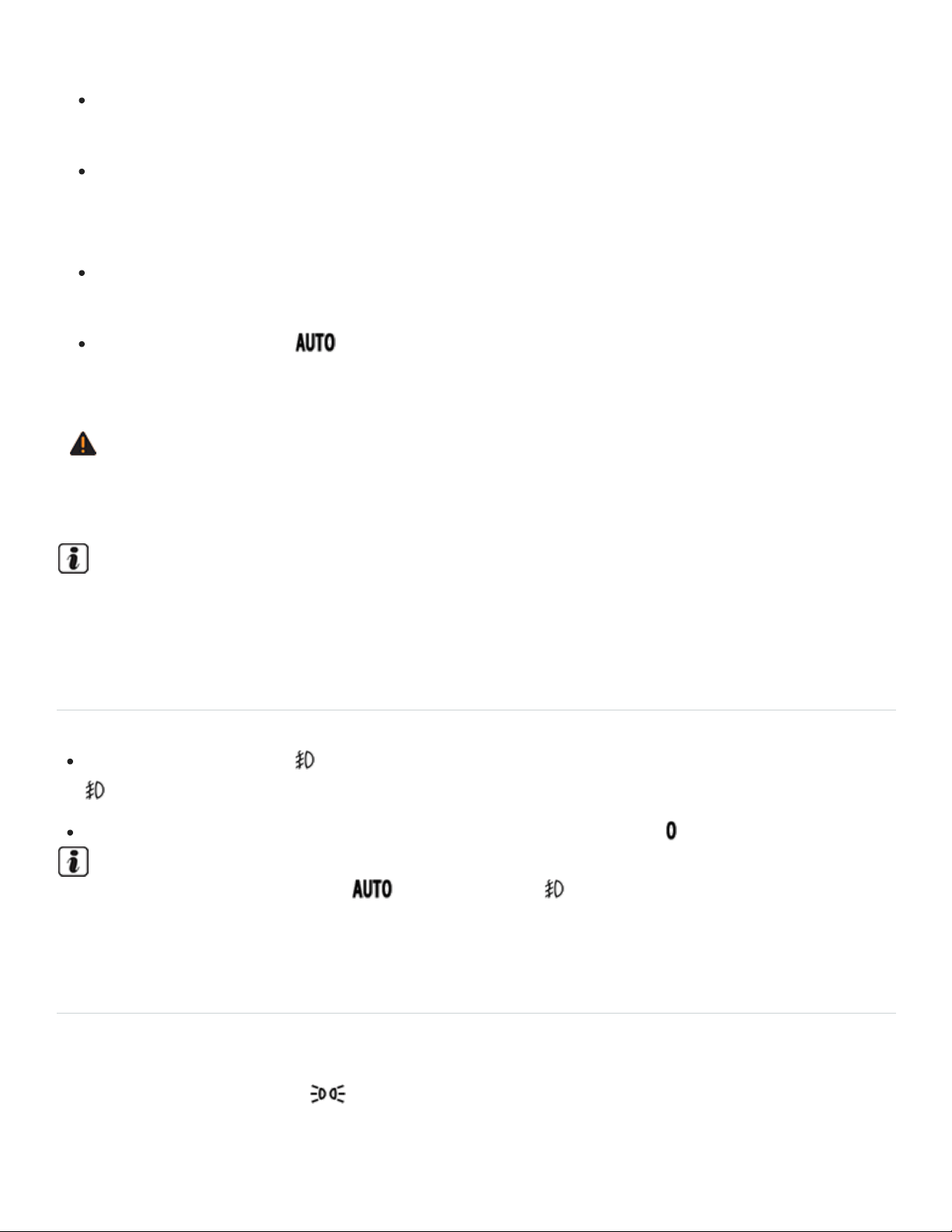
enough to let you see ahead or be seen by others when it is dark.
Always switch on the low-beam headlights at dusk, when it is dark, and whenever the weather
is bad or visibility is poor.
Never use the daytime running lights to see where you are going. They are not bright enough
and will not let you see far enough ahead for safety, especially at dusk or when it is dark.
Always switch on the low-beam headlights at dusk or when it is dark.
The taillights do not come on with the daytime running lights. Unless the taillights are on, a ve‐
hicle cannot be seen by others in bad weather, at dusk, or when it is dark.
If automatic headlights( ) are switched on, the low-beam headlights still may not be
switched on in fog or heavy rain. You have to switch on the low-beam headlights yourself.
WARNING
Improper use of high beams can distract and blind others, causing accidents and serious injuries.
In cool or humid weather, the insides of the headlights, the rear lights, and turn signals can tem‐
porarily fog up. This is normal and does not affect the service life of the vehicle's lighting system.
Switching the fog lights on and off
Switching on fog lights : Pull the light switch ⇒Fig.90 out to the detent. The indicator lamp
in the light switch lights up green.
To switch the fog lights off, push in the light switch or turn it to position .
When the automatic headlights and the fog lights are switched on, the low beams also
switch on, whether or not the low-light sensor registers darkness.
Lights – features
Parking lights
If the headlight switch is in the position and you do not switch the parking lights off when leaving
the vehicle, the parking lights stay on for about 30minutes before automatically switching off. This
feature helps prevent the parking lights from draining the vehicle battery if they were left on

unintentionally.
If the vehicle is not locked from the outside when the ignition is switched off, the parking lights will
stay on for about 10 minutes before automatically turning off. This helps to prevent unnecessary drain
on the vehicle battery.
Automatic headlights( )
Your vehicle may be equipped with automatic headlights( ), which are a convenience feature
only and cannot always recognize all lighting and driving situations.
If the light switch is in the position, both vehicle lighting and instrument and switch lighting are
automatically switched on and off in the following situations:
Automatic reactivation: If the low-light sensor registers darkness, for example, when driving
through a tunnel or at dusk OR when the rain sensor recognizes rain and switches the windshield
wipers on.
Automatic deactivation: If sufficient brightness is registered OR the windshield wipers have not
moved for several minutes.
You can adjust the level of darkness the vehicle must register before automatically switching on the
headlights in the Vehicle settings menu in the Infotainment system ⇒Infotainment system operation
and displays . You can also turn the automatic activation of the headlights with the rain sensors on
and off via this menu.
Cornering lights
Your vehicle may have cornering lights, which are either integrated into the headlights or the fog lights
under the front bumper. At speeds below about 25mph (40km/h), the light on one side of the vehicle
will come on automatically when you turn a corner. If you turn to the right, the right cornering light
comes on; turn left and the left cornering light comes on. The light dims and goes out when the steer‐
ing wheel is straightened out again.
When you move the selector lever to Reverse (R), the cornering lights on both sides of the vehicle
may come on so that you can see the area around the vehicle better when backing up.
The cornering lights work only when the headlights are on. If you are using automatic headlights
(headlight switch in the position ⇒Fig.90 ), they work only when the headlights have been auto‐
matically switched on. The cornering lights do not come on when the headlight switch is in the posi‐
tion or when the fog lights themselves have been switched on ⇒Switching lights on and off .

Acoustic warning when lights are not switched off
In the following situation, a warning chime will sound if you switch off the ignition and open the driver
door. This is to remind you that lights are still on.
Light switch in position .
NOTE
Leaving the parking lights on when the ignition is switched off can drain the vehicle battery.
Continuous parking lights
When the continuous parking lights are switched on, the parking lights and part of the taillights are on.
Turn the light switch to position .
Turn off the ignition.
Lock the vehicle from the outside.
Coming Home and Leaving Home features (orientation lighting)
Your vehicle may be equipped with ComingHome and LeavingHome features, which light up the
area around the vehicle when entering or exiting the vehicle in the dark.
The ComingHome and LeavingHome features are controlled automatically by a low-light sensor.
Switching on the Coming Home feature
Switch off the ignition.
The Coming Home feature is switched on when the headlight switch is in the position and the
low-light sensor registers darkness.
The ComingHome lighting switches on when the driver door is opened. The switch-off delay period
starts once the driver door is opened.
Switching off the Coming Home feature
The Coming Home feature switches off automatically after the preset delay period is over.
OR If a vehicle door or the trunk lid is still open about 30seconds after the feature switches on.

OR The light switch is turned to the position.
OR The ignition is switched on.
Switching on the Leaving Home feature
Unlock the vehicle.
The Leaving Home feature is switched on when the light switch is in the position and the low-
light sensor registers darkness.
Switching off the Leaving Home feature
The Leaving Home feature switches off automatically after the preset delay period is over.
OR When the vehicle is locked.
OR The light switch is turned to the position.
OR The ignition is switched on.
The length of time the lights stay on can be adjusted or the feature can be activated and deacti‐
vated in the in the Vehicle settings menu in the Infotainment system ⇒Infotainment system oper‐
ation and displays .
If the Coming Home feature is switched on and the driver door is opened, no warning chime will
sound to alert you that the lights are still on.
Tips and troubleshooting
When the ignition is switched on, several warning and indicator lights come on briefly for a function
check. They go out after a few seconds.
Vehicle lighting not working
The yellow indicator light comes on.
Light bulb of the exterior vehicle lighting not working.
See an authorized Volkswagen dealer, an authorized Volkswagen Service Facility, or other quali‐
fied workshop to replace the light bulb that isn't working.
Rain and light sensor malfunction

The yellow indicator light comes on.
The headlights will not switch on or off automatically when the light switch is in the position
⇒Rain sensor .
Switch the ignition off and back on.
If the indicator light comes on again and stays on, contact an authorized Volkswagen dealer or an
authorized Volkswagen Service Facility.
The turn signal indicator light blinks twice as fast
The green indicator light blinks twice as fast if a turn signal is not working on the vehicle.
Check the turn signals on the vehicle.
If the headlights are not properly adjusted
The headlight range cannot be manually adjusted. If you believe the headlights are not properly ad‐
justed or are not sure, have them checked immediately by an authorized Volkswagen dealer or an au‐
thorized Volkswagen Service Facility ⇒ .
WARNING
Failure to heed warning lights and instrument cluster text messages can result in a collision and
serious personal injury.
Never ignore warning lights or text WARNINGS.
Always stop the vehicle as soon as it is safe to do so.
Whenever stalled or stopped for repair, move the vehicle a safe distance off the road, stop the
engine, turn on the emergency flashers, and use other warning devices to warn approaching
traffic.
Never park the vehicle in areas where the hot catalytic converter and exhaust system could
come into contact with dry grass, brush, spilled fuel, oil, or other material that can catch fire.
A broken down vehicle presents a high accident risk for itself and others. Switch on emer‐
gency flashers and set up a warning triangle to warn oncoming traffic.
WARNING
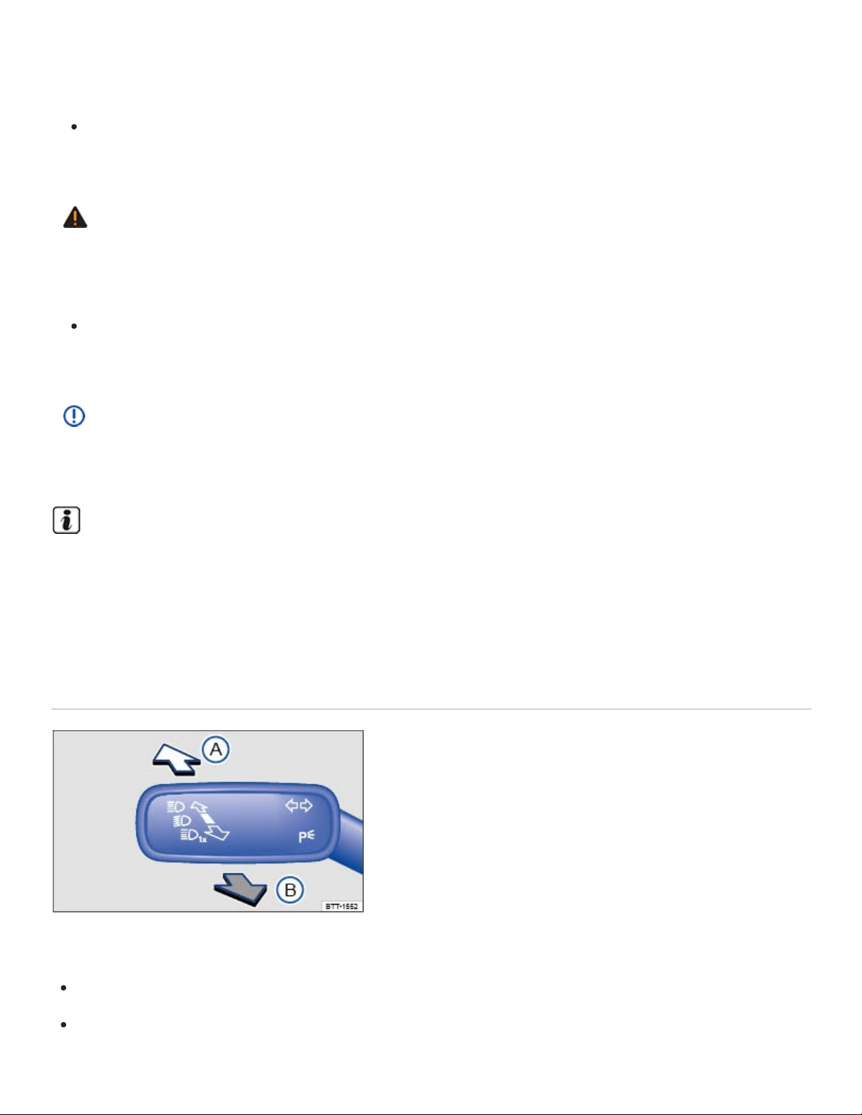
Headlights that are aimed too high because of the way the vehicle is loaded can blind and dis‐
tract other drivers. This can lead to a crash and serious personal injuries.
Always make sure the headlights are adjusted to loading conditions so that they do not blind
others.
WARNING
If the automatic leveling feature of the headlights does not work properly or at all, the headlights
could blind and distract other drivers. This can lead to a crash and serious personal injuries.
Have headlight range adjustment checked immediately by an authorized Volkswagen dealer or
an authorized Volkswagen Service Facility.
NOTE
Failure to heed warning lights or text WARNINGS can result in vehicle damage.
In cool or humid weather, the insides of the headlights, the rear lights, and turn signals can tem‐
porarily fog up. This is normal and does not affect the service life of the vehicle's lighting system.
High beams
Switching high beams on and off
Fig.91To the left of the steering wheel: Turn signal and high beam lever.
Switch on the ignition.
Switch on the headlights.

Move the turn signal and high beam lever from the center position to the following position
⇒Fig.91 :
High beams switched on.
Operate the headlight flasher or switch off the high beams. The headlight flasher turns on the
high beams as long as the lever is pulled and manually held in the pulled position.
When the high beams or headlight flasher is switched on, the blue indicator light in the instrument
cluster lights up.
High-beam control (Light Assist)
Your vehicle may be equipped with the Light Assist automatic high beam control system ⇒High-beam
control (Light Assist) .
WARNING
Improper use of high beams can distract and blind others, causing accidents and serious injuries.
High-beam control (Light Assist)
Your vehicle may be equipped with the Light Assist automatic high beam control system.
Light Assist high beam control
Light Assist generally detects well-lit areas such as towns and switches the high beam headlights off
when driving through these areas.
Light assist switches the high beam headlights on at speeds above about 37mph (60km/h), depend‐
ing on the surroundings and traffic conditions, and off again at speeds below about 18mph (30km/h),
within the limits of the system. ⇒ . The system is controlled by a camera mounted in the rearview
mirror base.
Switching Light Assist on
Switch the ignition on and turn the light switch to the position ⇒Switching lights on and off .
Push the turn signal lever forward (out of the home position) ⇒Switching high beams on and off .
When Light Assist is switched on, the indicator light appears in the instrument cluster display.
Switching Light Assist off

When the high beam headlights are on, pull the turn signal lever back to the home position.
OR Turn the light switch to a position other than ⇒Switching lights on and off .
OR When the high beam headlights are not on, push the turn signal lever forward to switch the
high beam headlights on manually. Light Assist switches off.
OR Switch the ignition off.
Adjusting Light Assist sensitivity
Light Assist has two sensitivity levels.
Increase sensitivity: Push the turn signal forward from the home position and hold for 15seconds.
The indicator light in the instrument cluster display flashes 3times to confirm the increased
sensitivity level.
Reset sensitivity to the factory setting: Push the turn signal lever forward from the home position a
second time and hold for about 15seconds. The indicator light in the instrument cluster dis‐
play flashes (quickly) 3times. OR: Turn the ignition off and back on again.
Light Assist system limits
The following conditions can prevent Light Assist from switching the high beam headlights off in time
or from switching them off at all:
Poorly lit roads with highly reflective signs.
If there are others on the road with insufficient lighting, such as pedestrians or bicycles.
In tight curves, when traffic is partially hidden, on steep hills, or in valleys.
On roads with a center barrier where the driver can clearly see oncoming traffic above the barrier,
for example, a truck driver.
In fog, snow, or heavy rain.
When there is dust or sand in the air.
If the windshield is hit by a stone and damaged in the area of the camera.
If the camera's visual field is fogged over, dirty, or covered by a sticker, snow, or ice.
If the camera is not working properly or the power is interrupted.
WARNING

Never let the increased convenience provided by Light Assist tempt you into taking extra risks.
The system is not a substitute for careful and attentive driving.
Always be prepared to control the headlights yourself and to adapt them to road, traffic,
weather, and visibility conditions.
Light Assist may not detect all traffic situations correctly and function may be restricted in cer‐
tain situations.
If the camera's area of view is dirty, covered, or damaged, Light Assist may not work properly.
Changes to the vehicle lighting system, such as by adding additional headlights, can also
change the way the systems work.
NOTE
To help the Light Assist system function properly, note the following:
Always keep the windshield in front of the camera clean and free of snow and ice; do not cover
the camera's field of view.
Check the windshield for damage in the area of the camera.
The illuminated display on an electronic device, for example, an external navigation device, may
prevent the Light Assist system from functioning properly.
Interior lighting
Instrument panel and switch lighting
Instrument cluster and switch brightness
You can adjust the brightness of the instrument cluster and switch lighting in the Vehicle settings
menu in the Infotainment system ⇒Infotainment system operation and displays .
The brightness of the instrument panel lighting changes in response to a change in lighting around
the vehicle, for example, when driving through a tunnel.
The instrument cluster lighting is on when the lights are turned off and the ignition is on. As the
lighting around the vehicle fades, the instrument cluster lighting will also fade and eventually turn
off. This is to remind the driver to turn on the low beams.

Interior and reading lights
Rear interior lights on.
Press the button to turn the door contact feature on and off. When the feature is switched on,
the interior lights come on automatically when the vehicle is unlocked or a door is opened.
The lights go out about 20seconds after you close the doors. They also go out when you
lock the vehicle or switch on the ignition.
Reading lights on or off.
Glove and luggage compartment lights
The glove and luggage compartments may have lights that come on automatically when they are
opened and go off when they are closed.
Ambient (background) lighting
The ambient lighting lights up in the driver and front passenger doors, the driver and front passenger
footwells, the instrument panel, and the cup holder in the middle console when the parking or low
beam lights are switched on.
On appropriately equipped vehicles, you can adjust the brightness and color of the ambient lighting in
the Vehicle settings menu in Infotainment system ⇒Infotainment system operation and displays .
For vehicles equipped with Driving Mode Selection, the ambient lighting changes depending on the
driving mode selected ⇒4MOTION Active Control . The ambient lighting must be set to Automatic in
the vehicle settings menu.
The interior and reading lights go out when you lock the vehicle or a few minutes after you re‐
move the vehicle key from the ignition. This helps to prevent unnecessary drain on the vehicle
battery.
Vision
Windshield wipers and washer
Windshield wiper lever
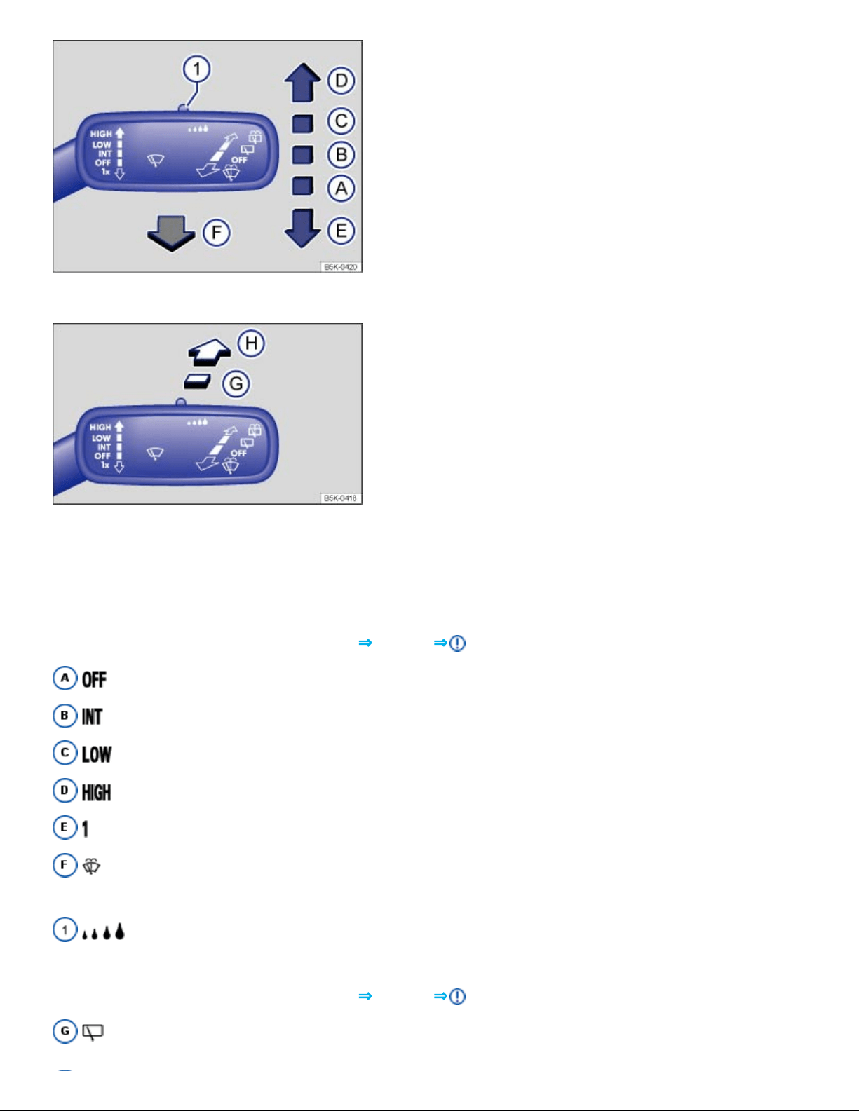
Fig.92Operating the front windshield wipers.
Fig.93Operating the rear wiper.
The windshield wipers work only if the ignition is switched on and the engine hood and trunk lid are
closed.
Move the lever to the desired position ⇒Fig.92 ⇒ :
Wiper switched off.
Intermittent wiping for the front windshield. Rain sensor active (if equipped).
Slow wiper speed.
Fast wiper speed.
x One-tap wiping – brief wiping. Hold the lever pressed down longer to wipe more often.
Pull the lever toward the steering wheel to switch on the front windshield washers, then
release.
Switch for adjusting the windshield wiper interval settings (vehicles without a rain sensor)
or the sensitivity of the rain sensor (vehicles with a rain sensor).
Move the lever to the desired position ⇒Fig.93 ⇒ :
Intermittent wiping for the rear window. The wiper wipes about every 6seconds.

Press the lever forward as far as it will go to switch on the rear window washers, then release.
This feature can be turned on and off in the Vehicle settings menu in the Infotainment system
⇒Infotainment system operation and displays .
WARNING
Windshield washer fluid without enough frost protection can freeze on the windshield and reduce
visibility.
Use the windshield washer system with enough frost protection for winter temperatures.
Never use the windshield wipers/washers when it is freezing without first defrosting the wind‐
shield. The washer solution may freeze on the windshield and reduce visibility.
WARNING
Worn or dirty wiper blades reduce visibility and increase the risk of accidents and severe injuries.
Always replace wiper blades that are worn, damaged, or do not keep the windshield clear.
NOTE
To help prevent damage to the wiper blades and the wiper motor when it is cold outside, always
make sure that blades are not frozen to the windshield before operating the wipers. Using the
service position can be helpful in cold weather so the wipers do not freeze to the windshield
⇒Windshield wiper service position .
If the ignition is switched off while the wipers are running, the wipers will continue at the same
wiping speed when the ignition is switched on again. Frost, ice, snow, leaves, and other ob‐
jects on the windshield can damage the wipers and the wiper motor.
Remove snow and ice from the wipers before you begin driving.
If the wiper blades freeze to the windshield, loosen them carefully. Volkswagen recommends
using a deicing spray.
NOTE
Never switch on the windshield wipers when the windshield is dry because the windshield can be
scratched.
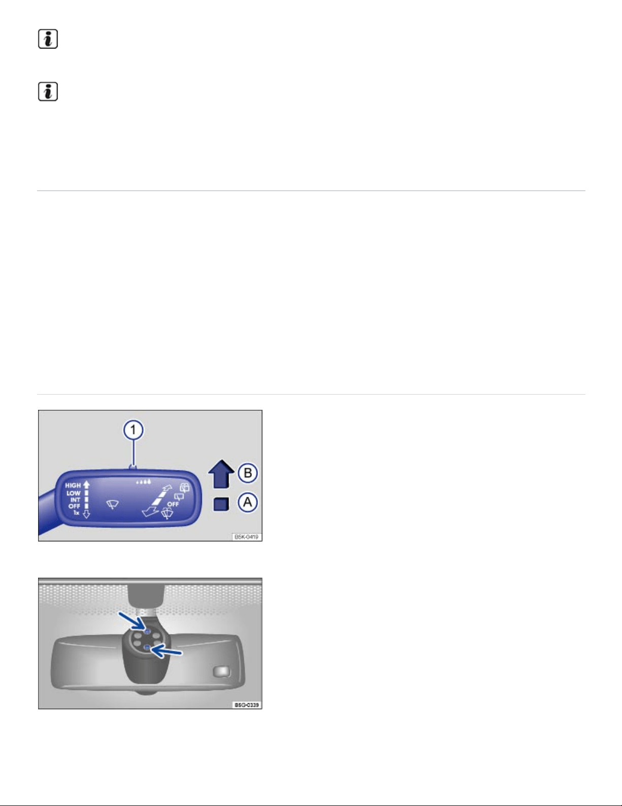
When the vehicle is not moving, the wiper speed changes temporarily to the next lower speed.
Certain settings are automatically saved by the driver personalization feature ⇒Driver
Personalization .
Windshield wiper functions
Heated washer nozzles (if equipped)
When the ignition is switched on, the heat applied to the washer nozzles is automatically regulated
depending on the outside air temperature. The heating thaws frozen washer nozzles, but not the fluid
supply hoses.
Wiper performance during intermittent wiping:
Speed-dependent interval control: The higher the vehicle speed, the faster the wipers move.
Rain sensor
Fig.94Windshield wiper lever: Adjusting the rain sensor ① (if equipped).
Fig.95Inside the front windshield above the inside mirror: Sensitive rain sensor surface (arrows).

When switched on, the rain sensor automatically shortens or lengthens the time between wiping inter‐
vals depending on how hard it is raining ⇒ .
Activating and deactivating the rain sensor
Position
Ⓐ
: Rain sensor off (windshield wiper lever home position).
Position
Ⓑ
: Rain sensor active - automatic wiping as needed.
After switching the ignition off and back on again, the rain sensor stays on and works again when the
wiper lever is in position
Ⓑ
.
The automatic wipe function of the rain sensor can be turned on and off in the Vehicle settings menu
in the Infotainment system ⇒Infotainment system operation and displays .
Setting the rain sensor's sensitivity
The rain sensor's sensitivity can be adjusted manually ⇒Fig.94① ⇒ .
Move switch to the right – high sensitivity.
Move switch to the left – low sensitivity.
WARNING
The rain sensor cannot always recognize rain and activate the wipers.
Switch the wipers on manually when water on the windshield reduces visibility.
Tips and troubleshooting
When the ignition is switched on, several warning and indicator lights come on briefly for a function
check. They go out after a few seconds.
Windshield washer fluid level too low
Your vehicle may be equipped with a yellow indicator light that comes on when the windshield washer
fluid level is low.
Refill windshield washer reservoir at the next opportunity ⇒Windshield washer fluid .
Rain and light sensor malfunction

The wipers do not switch on automatically if it rains, and the yellow indicator light comes on.
Switch the ignition off and on again.
If the indicator light comes on again and stays on, contact an authorized Volkswagen dealer or an
authorized Volkswagen Service Facility ⇒Rain sensor .
Windshield wiper malfunction
The wipers do not wipe and the yellow indicator light comes on.
Switch the ignition off and on again.
If the indicator light comes on again and stays on, contact an authorized Volkswagen dealer or an
authorized Volkswagen Service Facility ⇒Rain sensor .
If there are changes in the way the rain sensor works
The rain sensor may misread what is happening in the detection zone of its sensitive rain-sensor sur‐
face⇒Fig.95 (arrows) and not work for a number of reasons, which may include:
Worn out wiper blades: Worn out wiper blades may leave a film of water or wiping streaks; this
can cause the wipers to run longer, to wipe more often, or to wipe continuously at high speed.
Insects: Insects hitting the windshield may trigger the wipers.
Salt streaks: Salt streaks on the windshield from winter driving can cause wiping more often or
continuously on glass that is almost dry.
Dirt: Caked-on dust, wax, any other buildup on the windshield (lotus effect), or car-wash deter‐
gent residue can lower the rain sensor's sensitivity and cause it to react too slowly or not at all.
Clean the rain sensor's sensitive surface ⇒Fig.95 (arrows) regularly and check the wiper blades
for wear or damage.
Crack or chip in the windshield: If a stone hits and chips the windshield while the rain sensor is
on, this will trigger a wiper cycle. After that, the rain sensor will recognize the change and recali‐
brate itself to respond to the sensitive surface's reduced detection zone. Depending on the size of
the chip, the sensor's reaction pattern may or may not change.
To remove wax and coats of polish safely, Volkswagen recommends using an alcohol-based wind‐
shield cleaner.
WARNING

Failure to heed warning lights and instrument cluster text messages can result in a collision and
serious personal injury.
Never ignore warning lights or text WARNINGS.
Always stop the vehicle as soon as it is safe to do so.
If there is something on the windshield, the wiper will try to wipe it away. If it continues to block
the wiper, the wiper will stop moving. Remove the obstacle and switch the wiper on again.
Mirrors
Introduction to the subject
In this chapter you will find information on the following subjects:
⇒Inside mirror
⇒Outside mirrors
The outside mirrors and the inside mirror help you see and adapt your driving to traffic behind you.
Remember that the inside and outside rearview mirrors will not show everything behind you. There
can be blind spots. Blind spots can be significantly larger if the mirrors are not properly adjusted.
For your driving safety, it is important that you properly adjust the outside mirrors and the inside mirror
before you start driving ⇒ .
Looking in the exterior mirrors and the interior mirror does not allow the driver to see the entire side
and rear area of the vehicle. The area that cannot be seen is known as the blind spot. There may be
another vehicle, pedestrian, or object in the blind spot.
WARNING
Adjusting mirrors when the vehicle is moving can cause driver distraction, accidents, and serious
personal injury.
Always adjust the rearview mirrors when the vehicle is not moving.
Always be aware of what is happening around the vehicle when changing lanes, passing, turn‐
ing, or parking. Another vehicle, pedestrian, or object could be in your blind spot.

Always make sure mirrors are properly adjusted and the view to the rear is not reduced by
moisture, ice, snow, or other things.
WARNING
Self-dimming rearview mirrors contain an electrolyte fluid which can leak if the mirror glass is bro‐
ken. Electrolyte fluid can irritate the skin, eyes, and respiratory system.
Repeated or prolonged exposure to electrolyte fluid can irritate the respiratory system, espe‐
cially among people with asthma or other respiratory conditions. Get fresh air immediately by
leaving the vehicle or, if that is not possible, open windows and doors all the way.
If electrolyte fluid gets into the eyes, flush them thoroughly with large amounts of clean water
for at least 15minutes; medical attention is recommended.
If electrolyte fluid contacts skin, flush affected area with clean water for at least 15minutes and
then wash affected area with soap and water; medical attention is recommended. Thoroughly
wash affected clothing and shoes before reuse.
If swallowed, and the person is conscious, rinse mouth with water for at least 15minutes. Get
medical attention immediately. Do not induce vomiting unless instructed to do so by a medical
professional.
NOTE
Broken glass in the self-dimming rearview mirrors can cause electrolyte fluid leakage. Liquid
electrolyte leaked from a broken mirror glass will damage any plastic surfaces it comes in contact
with. Clean up spilled electrolyte fluid immediately with clear water and a sponge.
Certain settings are automatically saved by the driver personalization feature ⇒Driver
Personalization .
Inside mirror
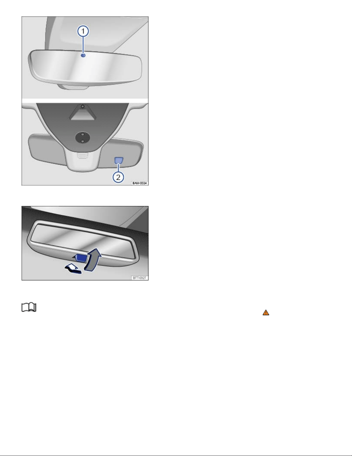
Fig.96On the windshield: Self-dimming rearview mirror.
Fig.97On the windshield: Manually adjustable rearview mirror.
Read and follow the introductory information and safety information first⇒ Introduction to the
subject
Adjust the inside mirror to make sure that there is good visibility through the rear window.
For example, visibility through the rear window could be impaired if there is a sunshade on the rear
window or clothing on the luggage compartment cover, or if the rear window is covered with ice,
snow, or dirt.
Self-dimming rearview mirror
When the ignition is switched on, the sensors on the mirror measure the amount of light shining into
the vehicle from the front ⇒Fig.96② and the rear ⇒Fig.96① of the vehicle.
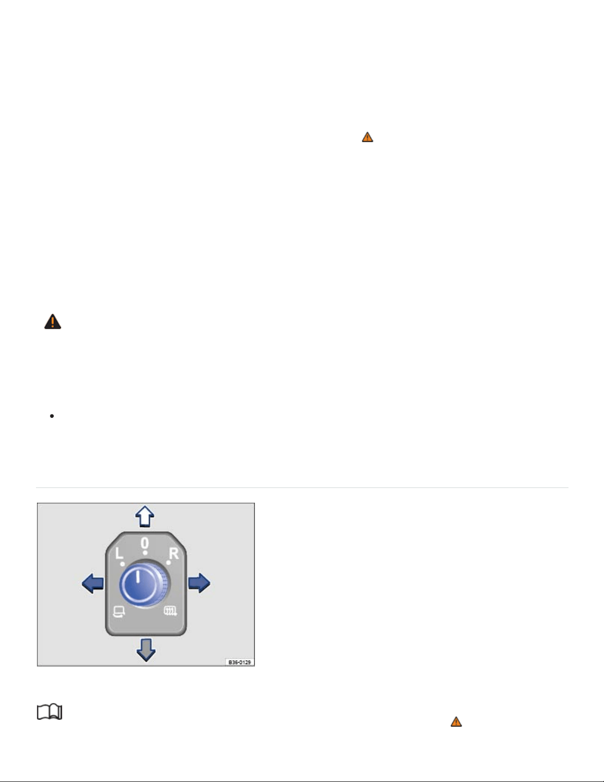
If the ignition is on, the mirror automatically darkens depending on the amount of light shining into the
vehicle from the rear.
If the light striking the sensor is filtered or blocked (such as by a sunshade), the self-dimming inside
mirror will not work properly or may not work at all. Do not attach external navigation devices to the
windshield or in the vicinity of the self-dimming inside mirror ⇒ .
The self-dimming feature is switched off when you shift the transmission into reverse or switch on the
interior lights or the reading light.
Manually adjustable rearview mirror
Home position: Lever on the bottom edge of the mirror points forward.
To adjust to non-glare visibility, move the lever so that it points down ⇒Fig.97 .
WARNING
The illuminated display on an electronic device, for example, an external navigation device, may
disrupt the self-dimming function of the rearview mirror, which may cause a crash and serious
injuries.
If the self-dimming function malfunctions, you may not be able to use the rearview mirror to
help judge the distance between traffic or other objects behind you.
Outside mirrors
Fig.98In the driver door: Adjusting knob for the outside mirrors.
Read and follow the introductory information and safety information first⇒ Introduction to the
subject

Adjusting the outside mirrors
Switch on the ignition.
Turn the rotary knob in the driver door ⇒Fig.98 to the desired position:
Fold the outside mirror in toward the vehicle body (if equipped) ⇒ .
Switch on outside mirror heating. Heats only at outside air temperatures below +68°F
(+20°C). Outside mirror heating works with maximum heat for about 2minutes.
Adjust the left outside mirror by pressing the knob to left/right and up/down.
Adjust the right outside mirror by pressing the knob to left/right and up/down.
Neutral position. No heating or adjustment possible.
Activating the exterior mirror features
Some exterior mirror features can be switched on and off in the Vehicle settings menu in the
Infotainment system ⇒Infotainment system operation and displays :
Synchronous mirror adjustment (if equipped)
The synchronous mirror adjustment feature simultaneously adjusts the right outside mirror when the
left outside mirror is adjusted.
Turn the outside mirror adjusting knob to the L position.
Adjust the left outside mirror. The right (passenger) outside mirror will automatically adjust at the
same time.
If needed, correct the position of the right mirror by turning the adjusting knob to the position.
Automatic mirror folding when parked (if equipped)
The adjusting knob must be in position , , or for the outside mirrors to fold in when the vehicle
is parked.
Turn on the automatic mirror adjustment feature in the Infotainment system, if necessary.
When the vehicle is locked from the outside, the outside mirrors automatically fold in.
When the vehicle is unlocked from the outside, the outside mirrors automatically fold out.
When the adjusting knob is in the position, the outside mirrors stay folded in.
Passenger side mirror lowering in reverse gear (if equipped)
Turn on the passenger side mirror lowering feature in the Infotainment system, if necessary.

Unlock the vehicle with the remote control vehicle key to which you want to save the settings.
Switch on the electronic parking brake.
Switch on the ignition.
Shift the transmission to Reverse (R).
Adjust the passenger outside mirror for a clear view of the curb, for example.
Turn the adjusting knob to the position.
The lowered mirror position is saved and assigned to the vehicle key.
Recalling the passenger side mirror settings
Turn the adjusting knob for the outside mirrors to the position.
Shift the transmission into Reverse (R) with the ignition switched on. The passenger side mirror
lowers to the saved position.
The passenger mirror moves back to the regular position when the vehicle moves forward faster
than about 10mph (15km/h) or the adjusting knob is moved from to another position.
WARNING
Improper use of the folding outside mirrors can cause personal injury.
Always make sure that nobody is in the way when folding the mirrors in or out.
Make sure that you do not get your finger caught between the mirror and the mirror base when
moving the mirrors.
WARNING
Incorrectly estimating distances with the right outside mirror can cause collisions and serious
injury.
The right outside mirror has a convex (curved) surface. This widens your field of vision. But ve‐
hicles or other objects seen in a convex mirror will look smaller and farther away than they re‐
ally are.
If you use the right outside mirror to judge distances from vehicles behind you when changing
lanes, you could estimate incorrectly and cause a crash and serious injuries.
Whenever possible, use the inside mirror to more accurately judge distance and size of vehi‐
cles or other objects seen in the convex mirror.
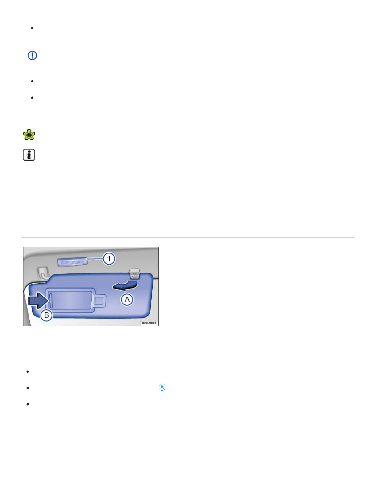
Always make sure you have a clear view to the rear of the vehicle.
NOTE
Always fold in the outside mirrors when taking the vehicle through an automatic car wash.
The electric motor in the electrically folding outside mirrors may be damaged if the mirrors are
folded by hand.
To reduce fuel consumption, use outside mirror heating only when needed.
If power mirror adjustment does not work, the outside mirrors can be adjusted by hand by press‐
ing on the edges of the mirror surface.
Sun protection
Sun visors
Fig.99Sun visor.
Adjusting the sun visors
Flip the sun visor down toward the windshield.
Lift it out of the retaining clip ⇒Fig.99
Ⓐ
.
Swivel the sun visor toward the door.
On some vehicles, you can slide the driver side sun visor toward the rear of the vehicle after swiveling
it toward the door.
Vanity mirror and lighting
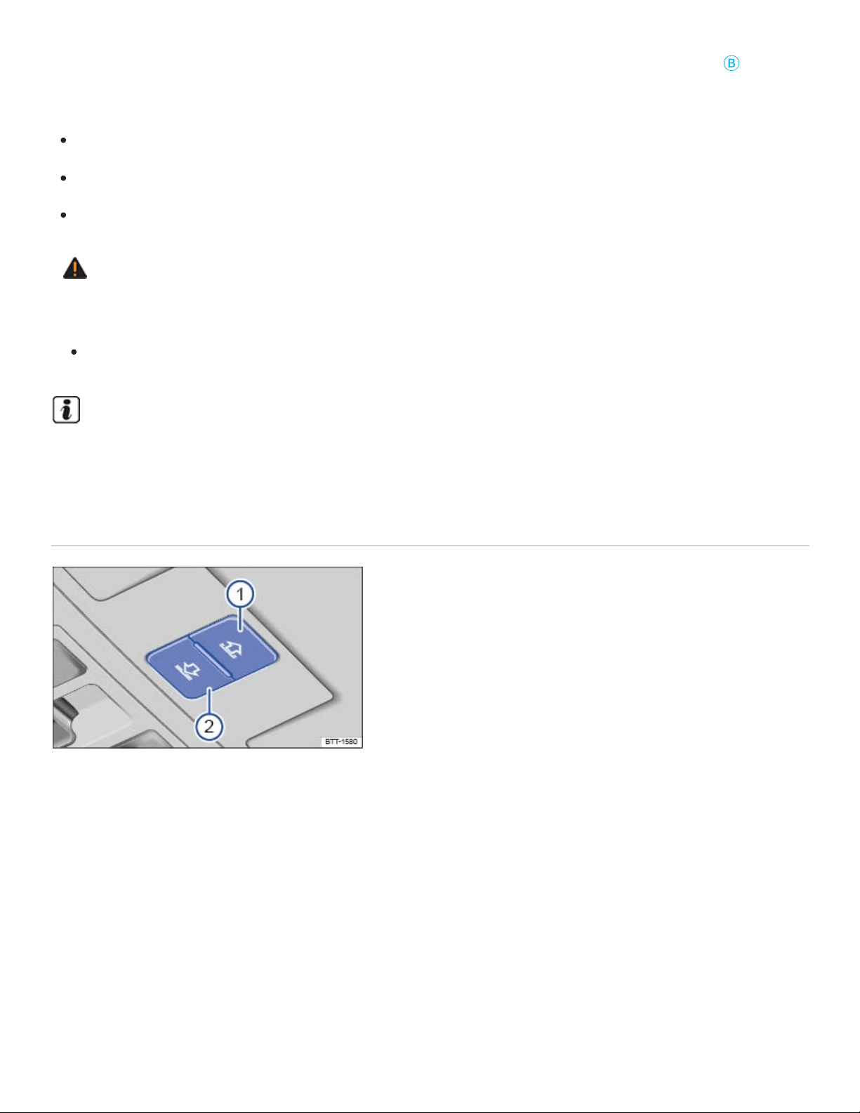
A vanity mirror is behind a cover in the sun visor. When you slide the cover open ⇒Fig.99
Ⓑ
, the
light ⇒Fig.99① comes on.
The cover is pushed closed.
The sun visor is flipped up again.
The sun visor is moved lengthwise or is not fully pushed in.
WARNING
Sun visors and sunshades can reduce visibility.
Always stow sun visors and sunshades when not needed to block sun glare.
The vanity mirror light goes out after several minutes. This helps to prevent unnecessary drain on
the vehicle battery.
Power sunshade in the sunroof
Fig.100In the roof console: Buttons for the power sunshade.
The power sunshade works when the ignition is switched on.
When the power sunroof is completely open, the sunshade is automatically moved to a ventilation po‐
sition. The sunshade stays in this position even when the sunroof is closed completely.
Opening and closing the sunshade
The buttons ⇒Fig.100① and ⇒Fig.100② have two detents.

Press the button to the first detent to completely or partially open or close the sunshade. Press the
button briefly to the second detent to open or close the sunshade with the one-touch feature (auto‐
matic opening or closing). Press the button again to stop the one-touch feature.
Open the sunshade: Press the button ① to the first detent. One-touch feature: Press ① to the sec‐
ond detent.
Close the sunshade: Press the button ② to the first detent. One-touch feature: Press ② to the sec‐
ond detent.
Stop the one-touch feature: Press button ① or ② again.
You can still use the sunshade for several minutes after the ignition is switched off as long as the
driver or passenger door has not been opened.
Pinch protection for the power sunshade
Pinch protection can help reduce the risk of pinching injuries when closing the power sunshade ⇒ .
If the power sunshade meets resistance while closing or there is something in the way, the sunshade
opens again immediately. When the sunshade is closed again after a short time, it will close without
pinch protection.
Check why the power sunshade did not close.
Try to close the power sunshade again.
If the power sunshade still cannot close, the power sunshade will stop where the resistance is lo‐
cated. The power sunroof will close the next time without pinch protection.
Closing the power sunroof without pinch protection
Press the button ⇒Fig.100② within about 5 seconds after the sunroof has stopped and hold it at
the second detent until the power sunroof closes completely.
The power sunroof will now close without pinch protection!
If the power sunroof still will not close, please see an authorized Volkswagen dealer or an autho‐
rized Volkswagen Service Facility.
WARNING
Without pinch protection, the power sunshade will close with enough force to cause serious per‐
sonal injury.
Always be careful when closing the power sunshade.
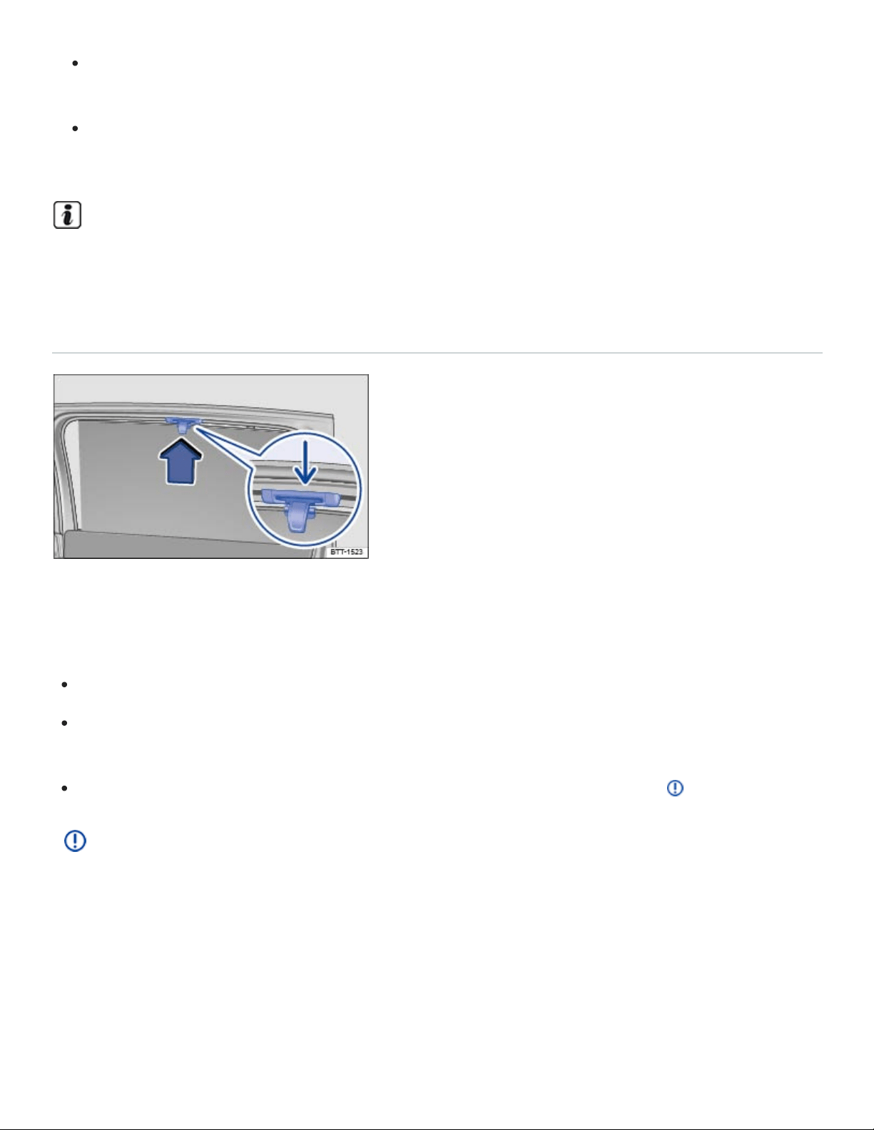
Always make sure that no one is in the way when overriding the pinch protection to close the
power sunshade!
Pinch protection cannot prevent fingers or other parts of the body from being pressed against
the edge of the roof; injuries may result.
When the sunroof is open, the power sunshade can be closed only to the front edge of the
sunroof.
Sunshades in the rear side windows
Fig.101Sunshade in the rear right window.
The sunshades for the rear side windows are integrated into the side trim of the respective window.
Pull the sunshade all the way up by the projecting handle ⇒Fig.101 .
Insert the handle into the corresponding mount ⇒Fig.101 (arrow). Make sure that both ends of
the sunshade handle are safely hooked into the mount.
To retract the sunshade, unhook the sunshade at the top and guide it down ⇒ .
NOTE
To help prevent damage to the shade or the interior rim, do not let the sunshade retract on its
own. Always guide the sunshade down.
Climate control
Heating and air conditioning

Introduction to the subject
In this chapter you will find information on the following subjects:
⇒Overview of the climate controls
⇒Air recirculation
⇒Seat heating and seat ventilation
⇒Steering wheel heating
⇒Windshield heating
⇒Tips and troubleshooting
Your vehicle may have the following equipment:
The manual air conditioning and the Climatronic climate control systems heat, cool, and dehumid‐
ify the air. The systems are most effective when the windows and sunroof are closed.
Air vents
To help ensure sufficient heating, cooling, and ventilation in the passenger compartment, never close
the air vents completely.
To open and close the air vents, turn the respective thumbwheel in the desired direction. When
the thumbwheel is turned all the way toward position , the air vent is closed.
Use the lever on the vent grille to adjust the airflow direction.
Additional air vents are in the instrument panel, in the footwells, and in the rear area of the passenger
compartment.
Dust and pollen filter
The dust and pollen filter reduces the entry of pollutants into the passenger compartment.
The dust and pollen filter must be replaced at the intervals recommended in ⇒BookletWarranty and
Maintenance, so that the air conditioner can work properly.

If the effectiveness of the filter decreases prematurely due to operating the vehicle where the outside
air is heavily polluted, the dust and pollen filter should be replaced more frequently than indicated.
WARNING
Poor visibility increases the risk of collisions and other accidents that cause serious personal
injuries.
Always make sure all windows are clear of ice, snow and condensation for good visibility to the
front, sides, and rear.
Always make sure you know how to properly use the climate control system as well as the rear
window defroster that you will need for good visibility.
Wait until you have good visibility before driving off.
Never use air recirculation for long periods of time. When the air conditioner is off and recircu‐
lation mode is on, condensation can quickly form on the windows and greatly reduce visibility.
Always switch off recirculation mode when it is not needed.
WARNING
Stale air causes driver fatigue and reduces driver alertness, which can cause accidents, colli‐
sions and serious personal injury.
Never switch off the fan for a long period of time and never use air recirculation for a long pe‐
riod of time because no fresh air will enter the passenger compartment.
NOTE
If you think the air conditioner is not working properly or may be damaged, switch it off to help
prevent more damage. Have the air conditioner checked by an authorized Volkswagen dealer
or an authorized Volkswagen Service Facility.
Air conditioner repair requires specialized knowledge and special tools. Volkswagen recom‐
mends that you see an authorized Volkswagen dealer or an authorized Volkswagen Service
Facility.
Do not smoke when air recirculation is switched on. Smoke drawn into the ventilation system
can leave residue on the evaporator and on the dust and pollen filter, resulting in permanent
odors whenever the air conditioner is switched on.

The heating elements for the rear defroster are on the inside of the rear window. Do not put
stickers over the heating elements on the inside of the rear window and never clean the inside
of the windows with corrosive, acidic, or abrasive cleaning agents, materials, or chemicals that
could damage the heating elements.
NOTE
Do not place food, medications, or other temperature-sensitive things in front of the air vents.
Food, medications, and other things that are sensitive to heat or cold can be damaged or made
unusable by the air flow from the vents.
The air coming out of the vents flows through the passenger compartment and through the air
vents in the luggage compartment. Do not cover these slots with clothing or other things.
If the air conditioner is switched off, the fresh outside air will not be dehumidified. To help keep
the windows from fogging over, Volkswagen recommends leaving the air conditioner (compres‐
sor) switched on. Press the button. The indicator light in the button must light up.
When it is very hot and humid outside, water condensation can drip from the air conditioner
evaporator and form a puddle under the vehicle. This is normal and does not indicate a leak.
Keep the air intake slots in front of the windshield free of ice, snow, and leaves in order to main‐
tain proper functioning of the heating and ventilation systems.
Maximum heating output and defrosting performance are not possible until the engine has
reached operating temperature.
Emergency starting and starting the engine with a very weak vehicle battery or after the vehicle
battery has been replaced may change or delete system settings (including time, date, driver per‐
sonalization, and programming). Check the settings and correct as necessary once the vehicle
battery has built up a sufficient charge.

Certain settings are automatically saved by the driver personalization feature ⇒Driver
Personalization .
Overview of the climate controls
Fig.102In the center console: Manual controls.
Fig.103In the center console: Climatronic controls.
Read and follow the introductory information and safety information first⇒ Introduction to the
subject
If a function is switched on, an indicator light in or under the button lights up.
Certain functions and buttons, as well rear controls, are optional and may not be present in all
vehicles.
– Settings in the Infotainment system (Climatronic only)
Press the button in the Climatronic controls to open the air conditioning settings in the
Infotainment system. Tap the corresponding function key to switch a function on or off, or to select a
submenu.
The current air conditioning settings are displayed in the upper section of the screen, for example, the
temperatures that are currently set for the driver and passenger sides. Blue arrows indicate that cool
air is flowing from the vents, while red arrows indicate that warm air is flowing from the vents.
The following menu items may be available, depending on vehicle equipment.
Tap the function key to set the air recirculation mode, the windshield heating, or the steering
wheel heating.
Tap the function key to access options for switching the air conditioner on and off ( ), adjust‐
ing the air distribution ( , , ), and switching air recirculation mode on or off ( ).
Tap the Presets function key to access options for automatic temperature control ( ), maxi‐
mum air conditioner cooling ( ), or for maximum defog/defrost ( ). In mode,
tap the blue bar at the left of each function key showing the current temperature to decrease the
temperature. Tap the red bar at the right of each function key to increase the temperature.
Tap the function key to set the fan speed in mode.
Switching the system off
Tap the function key.
Manual air conditioning: Turn the fan knob to ⇒Fig.102 .
Climatronic: Turn the middle knob as far left as it will go ⇒Fig.103 .
– Synchronize temperature settings (Climatronic only)
Press the button on the Climatronic controls to apply the temperature settings for the driver
side to the passenger side.
OR: Press the button on the Climatronic controls and tap the function key on the
screen.
If the indicator light in the button lights up, the temperature settings for the driver side also apply
to the passenger side. Pressing the button or turning the temperature knob on the passenger
side switches the feature off. The indicator light in the button goes out.
Automatic climate control and allergen filter (if equipped)
On appropriately equipped vehicles, the automatic climate control and allergen filter can help reduce
the entry of pollutants and allergens into the passenger compartment with an additional filter.
When the feature is active, the climate control system's air recirculation mode switches on to the high‐
est level possible without the windows fogging up, depending on the interior humidity and outside
temperature. The air recirculation mode is automatically regulated and features continuous adjust‐
ment to help prevent driver and passenger fatigue ⇒Air recirculation .
Press the button on the Climatronic controls.
Tap the Air Care function key on the Infotainment system screen.
Switch the feature on and off by tapping theActive function key.
– Switch off the climate control for the rear seats
Press the button to switch on or off the rear climate controls.
– Automatic regulation
Press the button to switch on automatic regulation. The indicator light in the button lights up.
Automatic regulation controls temperature, fan speed, and air distribution. If you change the fan
speed or air distribution manually, the automatic regulation switches off.
– Air conditioner
Press the button to switch the air conditioner on or off.
The air is dehumidified when the air conditioner is switched on.
– Maximum cooling
Manual air conditioning: Turn the left knob ⇒Fig.102 all the way to the left ( position).
Climatronic: Press the button for maximum air conditioner cooling. Air recirculation is
switched on automatically, and the air distribution is automatically set to position .
/ – Temperature
Manual air conditioning: Turn the left knob ⇒Fig.102 to set the temperature.
Climatronic: Turn the outside knobs ⇒Fig.103 to set different temperatures for the driver and
passenger sides.
Rear climate controls: Press the and buttons to set the temperature.
The displays above the knobs show the set temperature.

–Seat heating and seat ventilation (if equipped)
Switch the seat heating on by pressing the or buttons ⇒Seat heating and seat ventilation .
Switch the seat ventilation on by pressing the or buttons ⇒Seat heating and seat
ventilation .
– Steering wheel heating (if equipped)
Press the button in the center console to switch the steering wheel heating on and off
⇒Steering wheel heating .
OR: Press the button in the Climatronic controls, open the general settings submenu ,
and tap the function key on the Infotainment system screen.
– Residual heat
If the ignition is switched off and the engine is warm, the residual heat from the engine is used to con‐
tinue to heat the passenger compartment.
Press the button to turn the residual heat feature on or off.
When the residual heat feature is switched on, the indicator light in the button lights up. The fea‐
ture switches off after 30 minutes or if the vehicle battery is low.
– Fan speed
Turn the middle knob to adjust the fan speed.
Climatronic: LEDs in the knob light up to indicate the current fan speed. When automatic regulation (
) is switched on, the fan speed is not indicated in the knob.
–Air recirculation mode
Press the button to switch on air recirculation ⇒Air recirculation .
OR: Press the button in the Climatronic controls, open the climate control settings submenu
, and tap the function key on the Infotainment system screen.
Air distribution
: Air distribution to the upper instrument panel outlets.
: Air distribution to the footwells.

: Air distribution to the upper instrument panel outlets and footwells.
: Air distribution in the footwells, the upper instrument panel outlets, and to the windshield.
: Air distribution to the windshield and footwells.
: Air distribution to the windshield.
| – Defog/defrost
Manual air conditioning: Turn the right knob to position ⇒Fig.102 .
Climatronic: Press the button ⇒Fig.103 .
Manual air conditioning: The cooling system switches on and the air recirculation mode switches off
automatically to dehumidify the air. When the defrost function is switched on, the air recirculation
mode cannot be switched on, and the cooling system cannot be switched off.
Climatronic: The incoming outside air is directed to the windshield, and air recirculation automatically
switches off. Humidity is removed from the air at temperatures above about +35°F (+1.5°C), and the
blower is set to a high speed.
– Windshield heating
Climatronic: Press the button.
Tap the function key to switch windshield heating on or off. The engine must be running
⇒Windshield heating .
The windshield heating switched off automatically after a few minutes.
– Rear window defroster
Press the button to defrost the rear window.
The rear window defroster works only when the engine is running and switches off automatically after
10minutes or less.
Recommended settings for manual air conditioning
Switch off the air recirculation.
Set the fan to level or .
Turn the temperature knob to the center position.
Open and adjust all air vents in the instrument panel.
Turn the air distribution knob to the desired setting.
Press the button to turn on the air conditioner. The air will be dehumidified during cooling.
Recommended settings for Climatronic
Press the button.
Set the temperature to +72°F (+22°C).
Open and adjust all air vents in the instrument panel.
WARNING
Stale air causes driver fatigue and reduces alertness, which can cause accidents, collisions, and
serious personal injury.
Never switch off the fan for a long time because no fresh air will enter the passenger
compartment.
NOTE
To help prevent damage to the rear window defroster, do not place stickers over the heating lines
inside the vehicles.
If the function key is active in the Infotainment system, the rear climate controls cannot be
operated.
Air recirculation
Read and follow the introductory information and safety information first⇒ Introduction to the
subject
Air recirculation mode helps prevent outside air from entering the vehicle interior.
Switching manual air recirculation on and off
Press the button in the Climatronic controls to switch manual air recirculation on and off.

OR: Press the button in the Climatronic controls, open the climate control settings submenu
, and tap the function key on the Infotainment system screen.
The indicator light under the button comes on when air recirculation mode is switched on.
Switching the automatic air recirculation mode on and off (if equipped)
In automatic air recirculation mode, fresh air enters the passenger compartment. If the system detects
an increased concentration of pollutants in the outside air, it automatically switches to air recirculation.
As soon as the pollutant level is back in the normal range, air recirculation is switched off. Unpleasant
odors cannot be detected by the system.
Press the button on the Climatronic controls.
Tap the function key.
Switch automatic recirculation mode on or off by tapping the Automatic air recirculation function
key.
When does air recirculation mode switch off?
Air recirculation switches off in the following situations ⇒ .
Climatronic: the button is pushed.
OR: The function key in the Infotainment system is tapped.
Manual air conditioning: the air distribution knob is turned to .
A sensor detects conditions that could cause the windows to fog up.
WARNING
Stale air causes driver fatigue and reduces driver alertness, which can cause accidents, colli‐
sions and serious personal injury.
Never use air recirculation mode over an extended period of time, since no fresh air will enter
the passenger compartment.
When the air conditioner is off and recirculation mode is on, condensation can quickly form on
the windows and greatly reduce visibility.
Always switch off recirculation mode when it is not needed.
NOTE

Do not smoke when air recirculation is switched on. Smoke drawn into the ventilation system can
leave residue on the evaporator and on the dust and pollen filter, resulting in permanent odors
whenever the air conditioner is switched on.
Climatronic: When backing up and while the automatic wiper/washer is operating, air recirculation
is briefly switched on to help keep exhaust fumes from getting into the passenger compartment.
In very hot outside temperatures, temporarily switch to air recirculation in order to cool the vehicle
interior faster.
Seat heating and seat ventilation
Read and follow the introductory information and safety information first⇒ Introduction to the
subject
Depending on equipment, the front seats and outboard seats in the second row may be equipped
with seat heating. On some models, the front seats are equipped with both seat heating and seat ven‐
tilation. The seat heating and seat ventilation work when the engine is running.
The seat is ventilated with the air from the vehicle passenger compartment to wick away moisture
from the body. The seats are not directly cooled.
Volkswagen recommends setting the seat ventilation to a low level for longer rides.
Using seat heating
Switching on: Press the or button. The seat heating is at the maximum level.
Adjusting: Press the or button until the desired level is reached.
Switching off: Press the or button until all indicator lights are off.
The seat heating switches off every time that the ignition is switched off. If the ignition is switched
back on within about 10 minutes, the seat heating for the driver seat may switch back on automati‐
cally to the previous setting. The seat heating for all other seats must be turned on and readjusted
again.
Using seat ventilation

Switching on: Press the or buttons. The seat ventilation is at the maximum level.
Adjusting: Press the or buttons until the desired level is reached.
Switching off: Press the or buttons until all indicator lights are off.
The seat ventilation switches off every time that the ignition is switched off. If the ignition is switched
back on within about 10 minutes, the seat ventilation for the driver seat may switch back on automati‐
cally to the previous setting.
When should seat heating and seat ventilation not be used?
Do not use the seat heating or seat ventilation if any of the following conditions apply:
If you or a passenger suffers from a low level of perceived pain or a lowered awareness of pain as
from medication, paralysis, or chronic illness (e.g., diabetes) ⇒ .
If the seat is not being used.
If there is a child restraint installed on the seat.
If these is a blanket or seat cover on the seat.
If the seat is damp or wet.
Seat heating: If the outside temperature or the temperature inside the passenger compartment is
+77°F (+25°C) or higher.
WARNING
Certain medical conditions, such as paralysis and diabetes, and certain medications can increase
the risk of serious burns when the seat heating feature is switched on.
Vehicle occupants who have a low level of perceived pain or a lowered awareness of pain are
at risk of serious burns to the back, buttocks, and legs that take a long time to heal or may
never heal completely.
Never use the seat heating feature if you or your passengers are at risk of being burned be‐
cause of a medical condition. Take regular breaks and get out of the vehicle, particularly on
long trips. Consult your doctor for advice regarding your specific condition.
Never let exposed skin stay in contact with the seat upholstery when the seat heating is being
used.
WARNING

A wet seat can cause the seat heating to malfunction and increase the risk of serious burns.
Always make sure the seats are dry before using the seat heating.
Never sit on the seat with wet clothes.
Never put damp or wet things including clothes on the seat.
Never spill liquids on the seats.
NOTE
To help prevent damage to electrical and other parts in the seat, do not kneel on the front or
second row outboard seats or apply concentrated pressure to a small area of the seat or
backrest.
Liquids, sharp objects and things that do not let the heat in the seat escape into the air, includ‐
ing, for example, a child restraint, a blanket, or seat covers on the seat can damage seat
heating.
If you smell an odor, immediately shut off seat heating and have it checked by an authorized
Volkswagen dealer or authorized Volkswagen Service Facility.
Never install leather upholstery on a vehicle with seat heating that originally had cloth uphol‐
stery. The seat heating elements for seats with cloth seats will overheat if the cloth upholstery
is replaced with leather upholstery.
Switch off seat heating when it is not needed to help reduce unnecessary fuel consumption.
Seat covers may reduce the effectiveness of the seat ventilation feature.
Steering wheel heating
Read and follow the introductory information and safety information first⇒ Introduction to the
subject
Some vehicles with Climatronic controls are equipped with a steering wheel heating feature. The
heated steering wheel feature only works when the engine is running.
Switching the heated steering wheel feature on and off

Press the button in the upper center console.
Switching the heated steering wheel feature on and off in the Infotainment system
Press the button in the Climatronic controls.
Press the function key to switch the steering wheel heating on and off.
Adjusting the temperature setting
Press the button in the Climatronic controls.
Press the function key.
Press the Level function key.
The selected setting will stay stored after the ignition has been switched off. The temperature level for
the steering wheel heating is unrelated to the temperature setting for the seat heating.
Automatic deactivation
The steering wheel heating function switches off automatically if any of the following conditions apply:
If the seat heating for the driver seat is switched off (only when Link seat/steering wheel heating is
switched on).
If the overall energy consumption is too high.
If the heated steering wheel system malfunctions.
Windshield heating
Read and follow the introductory information and safety information first⇒ Introduction to the
subject
The windshield heating feature works when the engine is running.
Switching windshield heating on and off manually
Manual air conditioning: Tap the function key and then the Vehicle and function keys.
Climatronic: Press the button.
Tap the function key on the Infotainment system screen to switch windshield heating on or off.

The windshield heating switches off automatically depending on the outside temperature or after a
maximum of 8minutes.
The windshield heating switches off when the ignition is switched off. If the ignition is switched off and
back on again within a few minutes, the windshield heating may switch back on again automatically.
Automatic windshield heating (if equipped)
The windshield heating may switch on automatically if the climate control system detects conditions
that could cause the windows to fog up.
Press the button.
Tap the function key in the Infotainment system.
Tap the Automatic windschield heating function key to switch automatic windshield heating on or
off.
The automatic windshield heating is also active when the climate control system is switched off.
Windshield heating with the defrost feature
The windshield heating switches on when the defrost feature is switched on and the climate control
system detects conditions that could cause the windows to fog up.
Automatic switch-off conditions
The windshield heating will switch off automatically if one of the following conditions applies:
The vehicle's electrical load is too high.
There is a malfunction in the climate control system.
The feature has been switched on for the maximum amount of time.
Tips and troubleshooting
Read and follow the introductory information and safety information first⇒ Introduction to the
subject
If the climate control system switches off automatically or will not switch on
The air conditioner only works when the engine is running and the outside temperature is above
about +38°F (+3°C).

The air conditioner compressor switches off automatically when the engine is very warm.
Switch on the fan.
Check the fuse for the air conditioning system ⇒Replacing fuses .
Change the dust and pollen filter.
If there is still cause for concern, have the air conditioner checked by an authorized Volkswagen
dealer or authorized Volkswagen Service Facility.
If the heating system does not switch on or does not work as expected
The heating and defrost features are most effective when the engine is warm.
If there is a cause for concern, have the system checked by an authorized Volkswagen dealer or
authorized Volkswagen Service Facility.
If the windows fog up
Keep the air intake slots in front of the windshield free of ice, snow, and leaves so that the heating
and ventilation systems can work properly and to help prevent the windshield from fogging up.
Do not cover the air vents in the rear of the luggage compartment so that air can flow through the
passenger compartment from front to rear.
Press the button or turn the knob to to switch on the defog/defrost feature ⇒Overview
of the climate controls .
If the wrong temperature units are set
The inside and outside temperatures can be displayed in either Fahrenheit(F) or Celsius(C).
Change the temperature units in the Vehicle settings menu in the Infotainment system
⇒Infotainment system operation and displays .
If there is water under the vehicle
When it is very hot and humid outside, water condensation can drip from the air conditioner evapo‐
rator and form a puddle under the vehicle. This is normal and does not indicate a leak.
Driving
Information on driving safely and efficiently

Pedals
Fig.104Pedals in the driver footwell.
Key to ⇒Fig.104 :
Accelerator pedal
Brake pedal
All pedals must always be able to move freely in and out without interference from floor mats or other
things.
Only use floor mats that leave the pedal area free and are held securely in place with floor mat fas‐
teners to help prevent sliding.
WARNING
Objects in the driver footwell can prevent the pedals from moving freely. This can cause loss of
vehicle control and increase the risk of serious personal injuries.
Always make sure that nothing can interfere with the pedals.
Always fasten floor mats securely to the floor.
Never put floor mats or other floor coverings on top of already installed floor mats.
Always make sure that nothing can fall into the driver footwell while the vehicle is moving.
NOTE
Always make sure that the pedals are able to move freely and that nothing can interfere with
them. If a brake circuit fails, more brake pedal travel will be needed to bring the vehicle to a stop.
The brake pedal must be pressed farther and harder than normal.
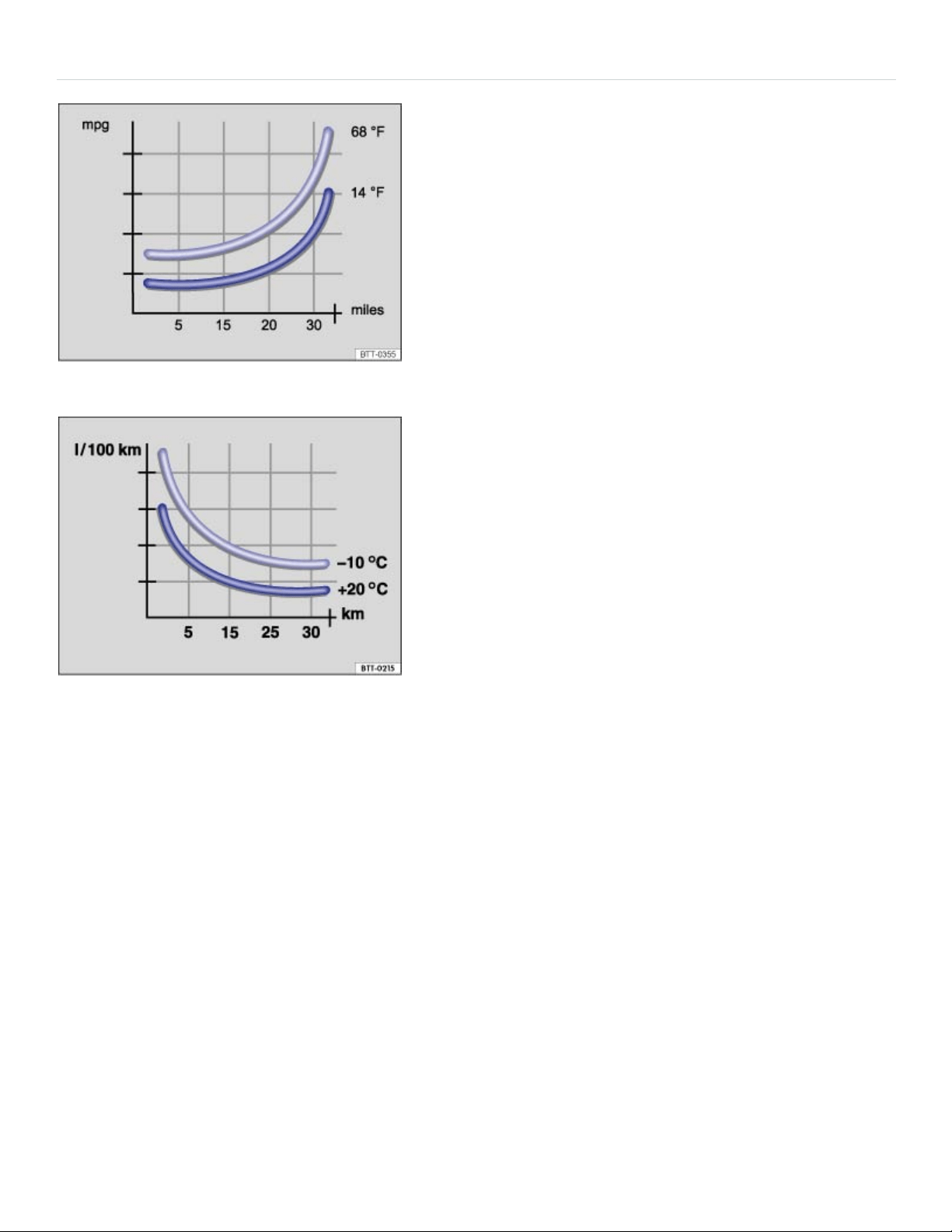
Efficient driving style
Fig.105Fuel consumption in miles per gallon (mpg) at twodifferent outside air temperatures.
Fig.106Fuel consumption in l/100km at twodifferent outside air temperatures.
Drive defensively
Frequent braking and acceleration increase fuel consumption significantly. By watching the traffic, you
can help avoid unnecessary braking and accelerating. If you keep enough distance from the car in
front of you, you can maintain a more constant speed. Active braking and accelerating is then not
necessarily required.
If possible, coast the vehicle to a stop, for example, when you can see that the next traffic light is red
or about to turn red.
Avoid full throttle acceleration
Driving at higher speeds uses more fuel. The air resistance and the power needed to move the vehi‐
cle increases at high speeds, for example over about 80 mph (130 km/h).
Reduce idling

In situations where the vehicle will be stopped for a longer period of time, such as at a railroad cross‐
ing, switch off the engine.
In vehicles with the Start-stop system, the engine will switch off automatically in many cases ⇒Start-
stop system .
Refuel in moderation
A completely full tank raises the weight of the vehicle. A partially-filled tank is plenty, especially in city
traffic.
Avoid traveling short distances
A cold engine uses a lot more fuel right after starting. It takes a few miles (km) before the engine is
warmed up and fuel consumption is stabilized.
Under the same conditions, the vehicle consumes more fuel in winter than in summer. Therefore,
avoid driving short distances unnecessarily and consolidate routes.
Letting the engine run to warm up is not only illegal in some places, but also technically not necessary
and wastes fuel.
Perform regular maintenance
Regular maintenance is necessary for fuel-efficient driving and helps extend the life of the vehicle.
Adjust the tire pressure
The proper tire pressure helps reduce rolling resistance as well as fuel consumption. When purchas‐
ing new tires, always make sure that the tires are optimized for lower rolling resistance.
Adjust the tire pressure according to the figures on the tire pressure label ⇒Tire inflation pressure .
Use low viscosity engine oil
Fully synthetic, low viscosity engine oils that expressly comply with Volkswagen oil quality standards
can help reduce fuel consumption. Low viscosity engine oils reduce the frictional resistance on the
engine and are distributed more evenly and quickly, particularly when cold-starting the engine. The
effect is particularly apparent in vehicles that frequently travel short distances.
Always ensure the right engine oil level is maintained and keep to the scheduled service intervals (en‐
gine oil changes).

Make sure the engine oil that you purchase expressly complies with Volkswagen oil quality standards
and is the oil approved by Volkswagen for your vehicle.
Avoid unnecessary weight
The lighter the vehicle, the more economical and eco-friendly it will be. For example, an extra 220lbs
(100kg) of weight increases fuel consumption by up to 1pint per 60miles (0.3l/100km). Remove
unnecessary dead weight from the vehicle.
The more aerodynamic the vehicle, the less fuel it will consume. Remove unnecessary items, such as
roof racks, from the vehicle.
Use extra electrical loads in moderation
Comfort inside the vehicle is important, but it is also important to use extra electrical loads in an envi‐
ronmentally conscious manner.
Saving energy can be easy, for example:
In hot outside temperatures, it may be helpful to ventilate the vehicle before driving and then to
drive a short distance with the windows open. After that, switch on the air conditioner with the win‐
dows closed. Keep the windows closed when driving at high speeds. Open windows increase
wind resistance and fuel consumption.
Switch off electrical loads once they have served their purpose.
WARNING
Always adjust your speed and driving style to visibility, road, traffic, and weather conditions.
NOTE
Never let the vehicle coast or roll down a hill in Neutral(N), especially when the engine is not run‐
ning. The transmission will not be lubricated and will be damaged.
Find out about other ways to protect the environment. Think Blue. is the international
Volkswagen brand for sustainability and environmental compatibility.
Your Volkswagen dealer or authorized Volkswagen Service Facility can provide you with addi‐
tional information about correct maintenance and replacement parts that are particularly fuel effi‐
cient, for example new tires.
®

Under the same conditions, the vehicle consumes more fuel in winter than in summer.
Think Blue. Trainer.
Fig.107Infotainment system screen: ThinkBlue.Trainer.
Your vehicle may be equipped with a ThinkBlue.Trainer. that analyzes your driving while the vehicle
is moving forward. It then generates a visual display which can help you to adopt a more fuel-efficient
driving style.
Key to ⇒Fig.107 :
The Blue Score is a rating of your driving style efficiency on a scale of 0to100. The higher the value
displayed, the more efficient your driving style. A blue frame around the display indicates a fuel-effi‐
cient and consistent driving style. A gray frame indicates a less efficient driving style.
You can touch the display to show the statistics for the last 30minutes of the current trip. If the current
driving time is less than 30minutes, the values from the last trip are displayed in gray.
The position of the two arcs in the outer ring shows the acceleration. At a constant speed, the arcs
appear in the central area. The arcs move up and down during braking and acceleration, respectively.
The white segment in the central ring shows the current evaluation status. It gradually moves clock‐
wise about every 5seconds, creating a blue segment each time. The blue segments in the central
ring show driving style efficiency. The larger the blue segment, the more efficient the driving style dur‐
ing this period.

Various symbols in the inner ring provide feedback about the current driving style:
:Think ahead while driving. :The current speed is not fuel-efficient.
:The current driving style is fuel-efficient.
The average fuel consumption is displayed in the units set by the driver, for example, Av.mpg or
Av.l/100km. The value refers to the distance traveled since the start of the trip. A blue frame around
the display indicates a fuel-efficient and consistent driving style. A gray frame indicates a less efficient
driving style.
You can touch the display to show the statistics for the last 30minutes of the current trip. If the current
driving time is less than 30minutes, the values from the last trip are displayed in gray.
Tap the Think Blue. function key for additional tips on saving fuel.
Displaying the Think Blue.Trainer.
When the vehicle is not moving, press the Infotainment button followed by the Vehicle, , and
Think Blue. Trainer. function keys.
OR: Press the Infotainment button until the ThinkBlue.Trainer. is displayed ⇒Infotainment sys‐
tem operation and displays .
WARNING
Never pay so much attention to the graphics shown on the screen that you fail to notice what is
going on around you.
Always pay close attention to what is happening around the vehicle.
About the brakes
New brake pads do not provide full performance during the first 100to 200miles (200to 300km)
and must first be broken in ⇒ . To some extent, you can make up for the somewhat reduced perfor‐
mance by applying more pressure to the brake pedal. But, during the break-in period, the stopping
distance for hard braking and emergency braking will be longer until the brakes are fully broken in.
Avoid hard braking and situations that might require hard braking (such as following other vehicles
too closely) – especially during the break-in period.
Brake pad wear depends mostly on operating conditions and the way the vehicle is driven. If you do
a lot of city and short-distance driving and/or have a sporty driving style, you should have the brake
pads checked by an authorized Volkswagen dealer or authorized Volkswagen Service Facility more

often than the regular service intervals.
Wet brakes (for example, after driving through water or washing the vehicle or after heavy rainfall)
will not brake as well. Stopping distances will be longer when brake discs are wet or, in winter, even
icy. Wet or icy brakes must be dried as soon as possible by carefully applying the brakes a couple of
times while traveling at a relatively high speed. Make sure nobody is behind you and that you do not
endanger yourself or others ⇒ .
Brakes coated with road salt also react slower and need longer stopping distances. If there is salt
on the roads and you are not braking regularly, brake carefully and gently from time to time to remove
any salt coating from the brake discs and pads ⇒ .
Brake disc corrosion (rust) and dirt buildup on the brake pads are more likely to occur if the vehicle
is not driven much or is driven only for short distances with little braking. If the brakes have not been
used and there is some rust on the discs, clean the brake discs and pads once in a while by carefully
braking a couple of times while driving at relatively high speed to help clean the brake discs and
pads. Make sure nobody is behind you and that you do not endanger yourself or others ⇒ .
Brake booster
The brake booster works only when the engine is running. It increases the force on the brakes above
and beyond the pressure put on the brake pedal by the driver.
If the brake booster is not working, or if the vehicle has to be towed, you will have to push the brake
pedal harder to make up for the lack of booster assistance and the resulting longer stopping distance
⇒ .
WARNING
Driving with bad brakes can cause a collision and serious personal injury.
If the brake warning light or does not go out, or lights up when driving, either the
brake fluid level in the reservoir is too low or there is a fault in the brake system. Stop the vehi‐
cle as soon as you can do so safely and get expert assistance ⇒Brake fluid .
If the brake warning light or lights up at the same time as the ABS warning light
or , the ABS may not be working properly. This could cause the rear wheels to lock up rela‐
tively quickly during braking. Rear wheel brake lock-up can cause loss of vehicle control.
If you believe the vehicle is safe to drive, drive slowly and very carefully to the nearest autho‐
rized Volkswagen dealer, authorized Volkswagen Service Facility, or other qualified workshop
and have the brake system inspected. Avoid sudden hard braking and steering.
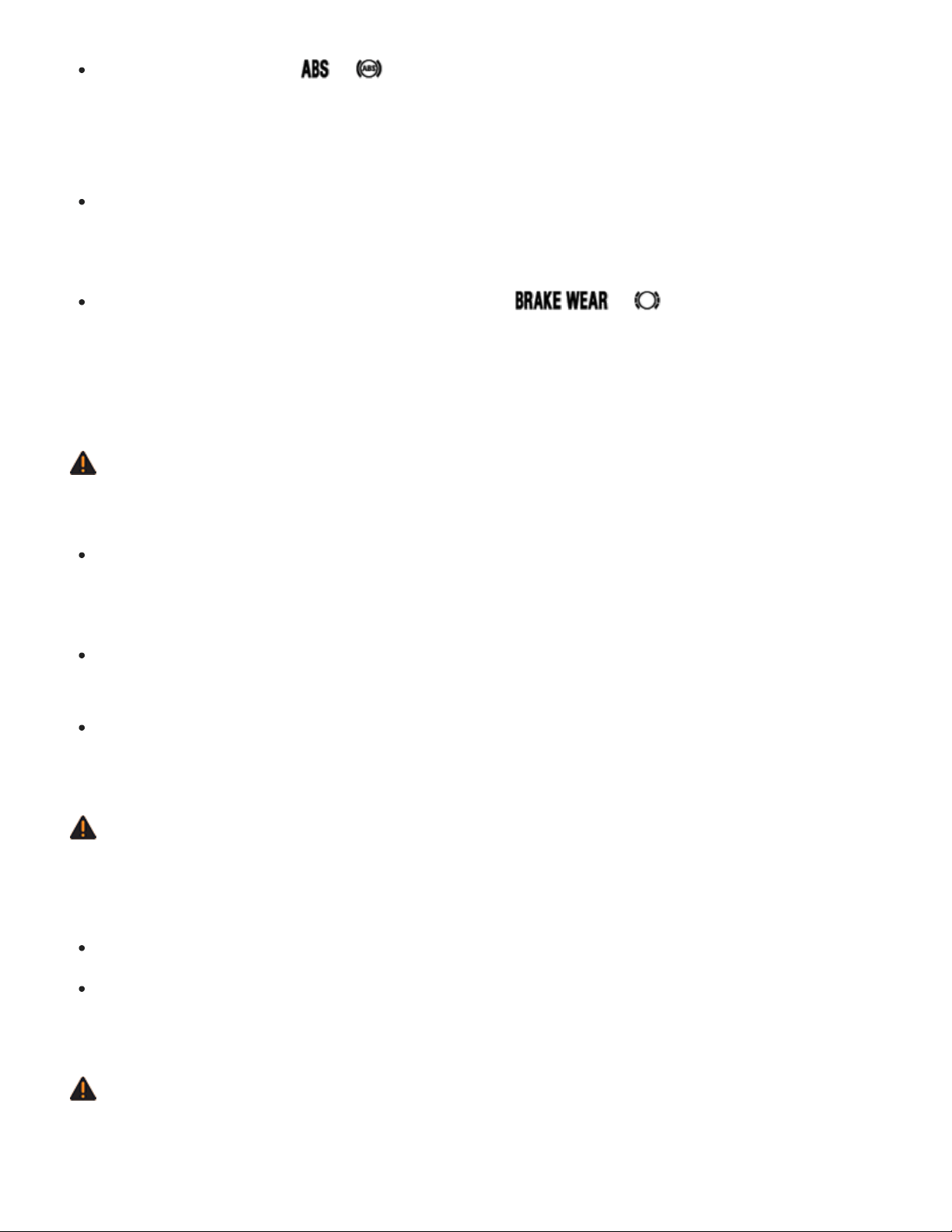
If the ABS indicator light or does not go out, or if it lights up while driving, the ABS sys‐
tem is not working properly. The vehicle can then be stopped only with the standard brakes
(without ABS). You will not have the protection ABS provides. Contact your authorized
Volkswagen dealer or an authorized Volkswagen Service Facility as soon as possible.
If the brake pads are worn or you notice changes in the way the vehicle brakes, immediately
contact an authorized Volkswagen dealer or authorized Volkswagen Service Facility to have
the brake pads checked and, if necessary, replaced.
Vehicles with a brake wear indicator: If the symbol or lights up in the instru‐
ment cluster display, whether alone or together with a text message, immediately contact an
authorized Volkswagen dealer or authorized Volkswagen Service Facility to have the brake
pads checked and, if necessary, replaced.
WARNING
New brake pads do not provide maximum braking performance.
New brake pads do not have the best stopping power for the first 200miles (300km) and must
be broken in. You can compensate for the slightly reduced braking force by putting more pres‐
sure on the brake pedal.
Drive with extra care while the new brake pads are being broken in. This reduces the risk of
collisions and serious personal injuries due to a loss of control over the vehicle.
Never follow other vehicles too closely or put yourself into other situations that might require
sudden, hard braking, especially when the brake pads have not been broken in.
WARNING
Constant braking causes the brakes to overheat and even to fail leading to collisions and serious
personal injury.
Never ride the brakes or apply the brake pedal too often or too long.
Riding the brakes will substantially reduce braking performance, increase stopping distance,
and can cause complete brake system failure.
WARNING
Overheated brakes will reduce the vehicle's stopping power and increase stopping distances
considerably.

When driving downhill, the brakes have to work especially hard and heat up quickly.
Before driving downhill, especially on hills that are long or steep, always reduce speed and
shift into lower gear. This will let the vehicle use engine braking and reduce the load on the
brakes. Otherwise, the brake system could overheat and possibly fail. Only use the brakes
when you need them to slow the vehicle down more or to stop.
A damaged front bumper or a non-standard spoiler can reduce airflow to the brakes and make
them overheat.
WARNING
Wet brakes or brakes coated with ice or road salt react slower and need longer stopping
distances.
Carefully apply the brakes to test them.
Always dry brakes and clean off ice and salt coatings with a few cautious brake applications
when visibility, weather, road and traffic conditions permit.
WARNING
Driving when the brake booster is not working increases stopping distances and can cause acci‐
dents and serious personal injuries.
Never let the vehicle coast when the engine is switched off.
If the brake booster is not working (such as when the vehicle is being towed), a lot more pedal
force is needed to slow down and stop.
NOTE
Never ride the brakes by keeping your foot on the brake pedal when you do not want to brake.
Constant pressure on the brake pedal can make the brakes overheat. Riding the brakes will
substantially reduce braking performance, increase stopping distance, and can cause com‐
plete brake system failure.
Before driving downhill, especially on hills that are long or steep, always reduce speed and
shift into lower gear. This will let the vehicle use engine braking and reduce the load on the
brakes. Otherwise, the brake system could overheat and possibly fail. Only use the brakes
when you need them to slow the vehicle down more or to stop.

When the front brakes are serviced, you should have the rear brake pads inspected at the same
time. The wear of all brake pads should be checked regularly by visually inspecting the pads
through the openings in the wheel rims or from underneath the vehicle. If necessary, the wheels
can be taken off for a more thorough inspection. See your authorized Volkswagen dealer or au‐
thorized Volkswagen Service Facility for more information.
Driving a loaded vehicle
For good handling when driving a loaded vehicle, please observe the following:
Securely stow all luggage ⇒Stowing luggage .
Drive especially carefully and accelerate gently.
Avoid sudden braking and driving maneuvers.
Brake earlier than you would if you were not driving a loaded vehicle.
If applicable, observe information about driving with a roof rack ⇒Roof rack .
If applicable, observe information about driving with a trailer ⇒Trailer towing .
WARNING
Heavy loads can change the way your vehicle handles and increase stopping distances. Heavy
loads that are not properly stowed or secured can shift suddenly, causing loss of control and seri‐
ous injury.
Secure the load properly to keep it from shifting.
Always remember when transporting heavy objects that they change the vehicle's center of
gravity and also the way it handles.
Always distribute the load as evenly as possible.
Secure heavy objects as far forward in the luggage compartment as possible.
Secure luggage in the luggage compartment using suitable straps and the tie downs
⇒Tie-downs . Also see ⇒Luggage compartment – features .
Always tie down heavy items securely with suitable straps.
Securely latch the rear seat backrest in the upright position.

Never exceed the Gross Axle Weight Rating or the Gross Vehicle Weight Rating on the safety
compliance sticker on the left door jamb. Exceeding permissible weight can cause the vehicle
to skid and handle differently.
Always adapt speed and driving to the heavier load and the weight distribution in the vehicle.
Take road, weather, traffic, and visibility conditions into account as well.
Always accelerate gently and avoid sudden braking and driving maneuvers.
Always brake earlier than you would if you were not driving a loaded vehicle.
Driving with an open trunk lid
Driving with an open trunk lid can lead to serious personal injury. If you have to drive with an open
trunk lid, make sure that all objects and the trunk lid itself are properly secured and take appropriate
measures to keep toxic exhaust fumes from entering the vehicle.
WARNING
Driving with an unlatched or open trunk lid can lead to serious personal injury.
Never transport objects larger than those that fit completely in the luggage compartment, be‐
cause the trunk lid cannot be fully closed properly.
After closing the trunk lid, always pull up on it to make sure that it is properly closed and can‐
not open suddenly when the vehicle is moving.
Always stow all objects securely in the luggage compartment. Loose objects can fall out of the
luggage compartment and injure others on the road behind you.
Drive carefully; anticipate what other drivers will do.
Avoid abrupt or sudden acceleration, steering, or braking, because the unlatched trunk lid can
move suddenly.
Always mark objects sticking out from the luggage compartment clearly for others to see.
Obey all applicable legal requirements.
Never use the trunk lid to clamp or hold objects that stick out of the luggage compartment.
Always remove any luggage rack or other rack mounted on the trunk lid (along with any lug‐
gage on the rack) before driving with an open trunk lid.
WARNING

Driving with an open trunk lid can cause poisonous carbon monoxide in the engine exhaust to get
into the passenger compartment. Carbon monoxide causes drowsiness, inattentiveness, poison‐
ing, and loss of consciousness. It can lead to accidents and severe personal injuries.
Always keep the trunk lid closed while driving to help keep poisonous exhaust fumes from be‐
ing drawn into the vehicle.
Never transport objects that are too large to fit completely into the luggage area, because then
the trunk lid cannot be fully closed.
If you absolutely must drive with an open trunk lid, do the following to reduce the risk of carbon
monoxide poisoning:
Close all windows and the power sunroof.
Switch off the climate control system's air recirculation feature.
Open all air vents in the instrument panel.
Set the fresh air fan to the highest speed.
NOTE
The open trunk lid changes the vehicle length and height.
Driving through water on roads
Note the following to help prevent vehicle damage when driving through water, for example on
flooded roads:
Check the depth of the water before driving through it. The water must not be any higher than
the bottom of the vehicle body ⇒ .
Do not drive faster than walking speed.
Never stop the vehicle, and do not drive in reverse or switch the engine off when driving through
water.
Oncoming vehicles may create waves that raise the water level and make it too deep for your ve‐
hicle to drive through safely.

Always manually deactivate the start-stop system before driving through water ⇒Start-stop sys‐
tem .
WARNING
After driving through water, mud, sludge, etc., the brakes react slower and need longer stopping
distances.
Always dry the brakes and clean off any ice coatings with a few careful applications of the
brake. Make sure not to endanger other motorists or cyclists or disobey legal requirements.
Avoid abrupt or sudden braking maneuvers immediately after driving through water.
NOTE
Vehicle components such as the engine, transmission, suspension or electrical system can be
severely damaged by driving through water.
Never drive through salt water. Salt causes vehicle corrosion. Thoroughly rinse with fresh wa‐
ter all vehicle parts that were exposed to salt water.
Break-in period
A new engine must be carefully broken in during the first 1000miles (1600kilometers). During the
first few hours of driving, the engine's internal friction is higher than later when all moving parts have
been broken in.
Breaking in a new engine
Do not use full throttle.
Don't let the engine speed get above 2/3 of the maximum speed.
Do not tow a trailer.
Speed may gradually be increased to maximum permissible road and engine speed.
Engine life is influenced by how you drive the vehicle for the first 1000miles (1600km). Even after‐
wards, driving at moderate engine speeds, especially when the engine is cold, will tend to reduce en‐
gine wear and help the engine to last longer and go farther. But do not drive at an excessively low en‐
gine speed, either. Always downshift if the engine is not running smoothly.
New tires and brake pads

Note applicable requirements for breaking in new parts.
New tires and replacement tires ⇒Tires and wheels .
Brakes ⇒About the brakes .
Breaking in a new engine gently will increase service life and reduce oil consumption.
Tips and troubleshooting
Brake system malfunction
The red warning light comes on.
A text message may also appear in the instrument cluster.
Stop!
If you believe the vehicle is safe to drive, immediately take it to the nearest authorized
Volkswagen dealer or authorized Volkswagen Service Facility for repair. Drive slowly and very
carefully, allow for the longer stopping distance, and be ready to push longer and harder on the
brake pedal to slow the vehicle down.
Brake pads worn
Vehicles with brake wear indicator: The red warning light or the yellow indicator light come on.
The brake pads are worn.
If you believe that it is safe to do so, immediately take the vehicle to an authorized Volkswagen
dealer or authorized Volkswagen Service Facility.
Have all the brake pads checked, and, if necessary, replaced.
If the vehicle braking performance changes
Immediately contact an authorized Volkswagen dealer or authorized Volkswagen Service Facility
for assistance.
WARNING
Failure to heed warning lights and instrument cluster text messages result in a collision and seri‐
ous personal injury.
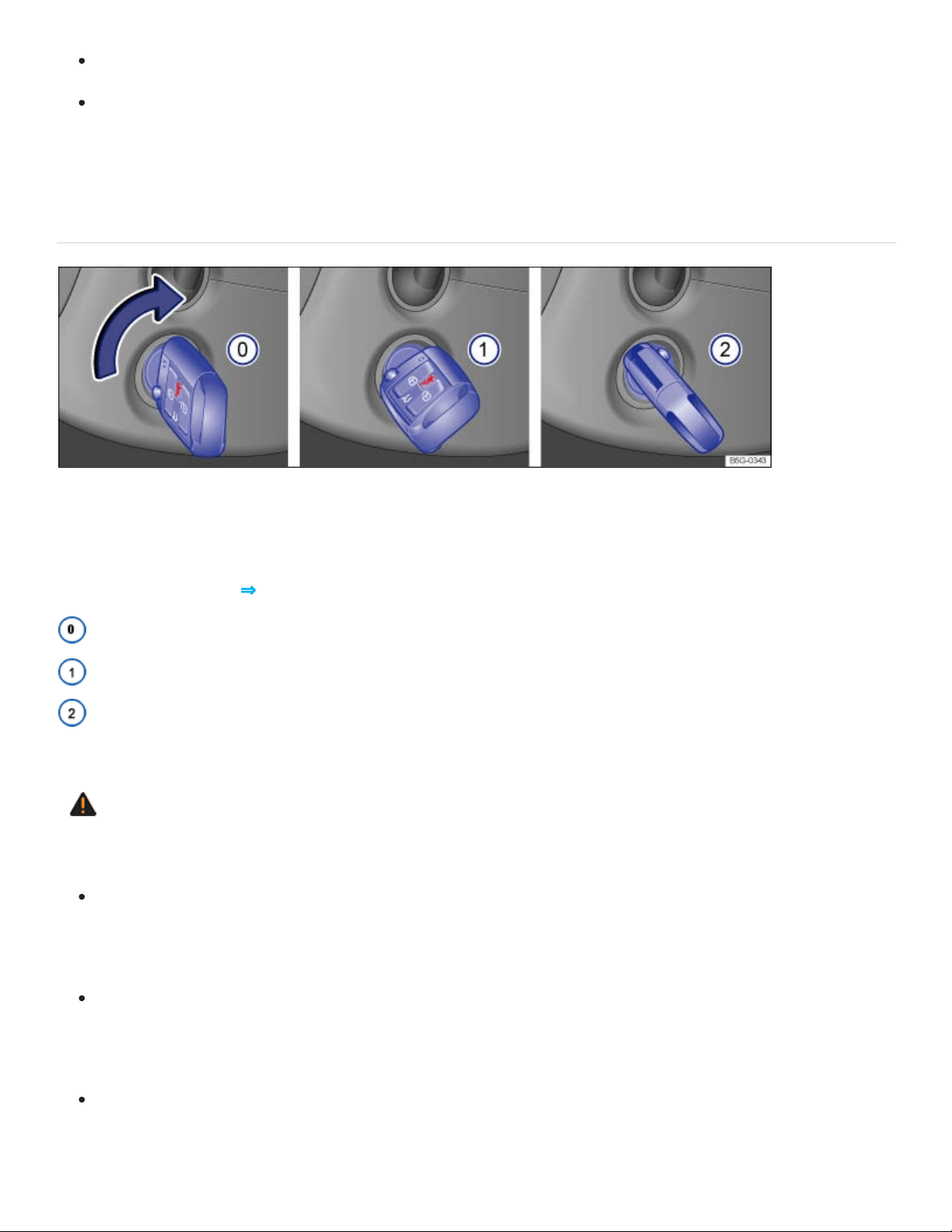
Never ignore warning lights or text WARNINGS.
Always stop the vehicle as soon as it is safe to do so.
Starting and stopping the engine
Ignition switch
Fig.108In the ignition switch: Vehicle key positions for vehicles without Keyless Access.
If there is no vehicle key in the ignition, the steering column is locked.
Vehicle key position ⇒Fig.108
Ignition switched off. Steering column lock engaged. The vehicle key can be removed.
Ignition is switched on. Steering column lock can be released.
Start the engine. When the engine starts, release the vehicle key. When released, the vehicle key
returns to position ①.
WARNING
Improper use of vehicle keys can result in serious personal injury.
Always switch off the engine and the ignition and take the key with you when you leave the ve‐
hicle. The engine can be started and vehicle systems such as the power windows can be op‐
erated, leading to serious personal injury.
Never let the engine run in a confined or enclosed area. Engine exhaust contains carbon
monoxide, a poisonous, colorless, and odorless gas. Carbon monoxide can cause uncon‐
sciousness and death.
Never leave children, disabled persons, or anyone who cannot help themselves in the vehicle.
The doors can be locked with the remote control vehicle key. This could result in people being

trapped in the vehicle in an emergency. For example, depending on the time of year, people
trapped in the vehicle can be exposed to very high or very low temperatures.
Never leave children or disabled persons in the vehicle – particularly if the ignition is on or a
remote control vehicle key is also in the vehicle. Unsupervised use of the remote control vehi‐
cle key also makes it possible to start the engine, or turn on the ignition and operate the win‐
dows as well as other vehicle features.
Heat buildup in the passenger and luggage compartment of a parked vehicle can result in tem‐
peratures in the vehicle that are much higher than the outside temperatures, particularly in
summer. Temperatures can quickly reach levels that can cause unconsciousness and death,
particularly to small children.
Never remove the key from the ignition switch while the vehicle is moving or rolling to a stop.
The steering wheel will lock and you will not be able to steer or control the vehicle.
Only attach lightweight objects to the remote control vehicle key that weigh no more than a
combined total of 3.5oz (100g).
NOTE
Leaving the ignition on for a long time when the engine is not running will drain the vehicle
battery.
Always switch off the ignition and remove the key before leaving the vehicle.
The remote control vehicle key can be removed from the ignition switched only when the selector
lever is in park (P).
Leaving the selector lever for a long period of time in any position other than Park (P) when the
ignition is switched off can drain the vehicle battery.
Starter button

Fig.109In the lower center console: Starter button for the Keyless Access system.
For vehicles with Keyless Access with push-button start ⇒Doors and power locking system , the ve‐
hicle can be started and stopped with the starter button in the lower center console ⇒Fig.109 .
The starter button can only be used when an authorized vehicle key is in the vehicle.
When leaving the vehicle, the electronic steering column lock is activated when the ignition is
switched off and the driver door is opened ⇒Steering .
Switching the ignition on and off
Briefly press the starter button once without depressing the brake pedal ⇒ .
Automatic ignition switch-off for vehicles with the Start-stop system
The vehicle ignition switches off automatically when the vehicle is standing still, the Start-stop system
is switched on ⇒Start-stop system , and ALL of the following conditions are met at the same time:
The driver safety belt is unbuckled.
No pedal is depressed.
The driver door is opened.
If the ignition is switched off automatically while the headlights are switched on , the parking lights
stay switched on for about 30minutes.
The parking lights can be switched off manually or will turn off when the vehicle is locked.
WARNING
Unintended vehicle movement can cause serious personal injury.
Do not depress the brake pedal when switching on the ignition, as the engine could otherwise
start immediately.

WARNING
Improper use of vehicle keys can result in serious personal injury.
Always switch off the engine and the ignition and take the key with you when you leave the ve‐
hicle. Children or unauthorized persons may use it to lock the vehicle, start the engine, and op‐
erate vehicle systems such as the power windows, leading to serious personal injury.
Never let the engine run in a confined or enclosed area. Engine exhaust contains carbon
monoxide, a poisonous, colorless, and odorless gas. Carbon monoxide can cause uncon‐
sciousness and death.
Never leave children, disabled persons, or anyone who cannot help themselves in the vehicle.
The doors can be locked using the remote control vehicle key. This could result in people be‐
ing trapped in the vehicle in an emergency. For example, depending on the time of year, peo‐
ple trapped in the vehicle can be exposed to very high or very low temperatures.
Never leave children or disabled persons in the vehicle – particularly if the ignition is on or a
remote control vehicle key is also in the vehicle. Unsupervised use of the remote control vehi‐
cle key also makes it possible to start the engine, or turn on the ignition and operate the win‐
dows as well as other vehicle features.
Heat buildup in the passenger and luggage compartment of a parked vehicle can result in tem‐
peratures in the vehicle that are much higher than the outside temperatures, particularly in
summer. Temperatures can quickly reach levels that can cause unconsciousness and death,
particularly to small children.
If the ignition is switched on or the engine is running and the driver door is opened, a chime
sounds. The chime is also a reminder to switch off the engine and turn off the ignition before leav‐
ing and locking the vehicle from the outside.
Always switch off the engine and ignition before leaving the vehicle. Read and follow any informa‐
tion in the instrument cluster display.
Leaving the ignition on for a long time when the engine is not running will drain the vehicle battery
and the engine may not start.
Starting the engine

Starting the engine
Checklist
Depress the brake pedal and hold it down until step4 is completed.
Make sure the transmission is in Park(P).
Turn the vehicle key to position ② OR briefly press the starter button Starter button. Do not de‐
press the accelerator pedal.
If the engine does not start, switch off the ignition and start again after about 1minute.
Release the parking brake when you are ready to start driving Electronic parking brake.
WARNING
To reduce the risk of serious personal injury when starting and running the vehicle's engine:
Never start the engine or let it run in a confined or enclosed area. Engine exhaust contains
carbon monoxide, a poisonous, colorless, and odorless gas. Carbon monoxide can cause un‐
consciousness and death.
Never start the engine or let it run if oil, fuel, or other flammable substances are under, around,
or have leaked from the vehicle, for example, due to vehicle damage.
Never leave the vehicle unattended with the engine running, especially when it is in gear. The
vehicle could move suddenly or some other unexpected event could occur, resulting in prop‐
erty damage, fire, or personal injury.
Never use starting assist fluids. Starting fluids can explode and can cause a run-away vehicle
condition.
NOTE
You can damage the starter or the engine if you try to start the engine when the vehicle is still
moving, or if you try to restart the engine right after switching it off.
Avoid high engine speeds, full throttle acceleration, and heavy engine loads when the engine
is cold.
Do not try to start the engine by pushing or towing the vehicle. Unburned fuel can get into the
catalytic converter and damage it. The steering column may also be locked. Jump-start the ve‐
hicle instead while following proper and safe procedures ⇒Jump-starting .

Do not let your vehicle warm up while standing; instead, start driving right away after making sure
that you have good visibility through all windows. This will help the engine reach operating tem‐
perature faster and keep down emissions.
Major consumers of electricity are temporarily switched off when the engine is being started.
If the remote control vehicle key battery is weak or dead, you may not be able to start the engine
with the starter button. Use the emergency start feature ⇒If the engine does not start .
After starting a cold engine, there may be increased operating noises for a few seconds. This is
normal and harmless.
Stopping the engine
Stopping the engine
Checklist
Bring the vehicle to a complete stop .
Depress and hold down the brake pedal until step4 is completed.
Shift the transmission into Park (P).
Set the parking brake to help prevent the vehicle from moving Electronic parking brake.
Turn the vehicle key toposition
⓪
in the ignition switch OR briefly press the starter button
Starter button.
Vehicles without Keyless Access: Removing the vehicle key from the ignition switches off electrical
equipment and activates the steering column lock.
Vehicles with Keyless Access: Opening the doors switches off electrical equipment and activates the
steering column lock.
If you leave the ignition on
If you leave the ignition on and open the driver door, a warning message may appear in the instru‐
ment cluster. In addition, you may also hear an acoustic warning. This warning reminds you to switch
off the ignition before leaving the vehicle ⇒ .

WARNING
Never stop the engine before the vehicle has come to a complete stop. You can lose control of
the vehicle, crash, and be seriously injured.
The airbags and safety belt pretensioners will not work when the ignition is switched off.
The brake booster does not work when the engine is not running. More brake pedal pressure
will be needed to stop the vehicle.
The power steering system does not work when the engine is not running, and you will need
more force to steer the vehicle.
Never remove the key from the ignition switch or turn off the ignition with the starter button
while the vehicle is moving or rolling to a stop. The electronic steering column could suddenly
lock, you would not be able to steer, and you could lose control of the vehicle, crash, and seri‐
ously injure yourself and others.
WARNING
The vehicle exhaust system and the catalytic converter get very hot. They can cause fires and
serious personal injury.
Never park where the hot exhaust system could ignite flammable materials, such as brush,
leaves, dry grass, spilled fuel, etc.
Never apply additional anti-corrosion or underbody protection products to the vehicle heat
shields.
WARNING
To reduce the risk of serious personal injury when you leave the vehicle.
Always switch off the engine and ignition and take the key with you when you leave the vehi‐
cle. Never let the engine run in a confined or enclosed area. Engine exhaust contains carbon
monoxide, a poisonous, colorless, and odorless gas. Carbon monoxide can cause uncon‐
sciousness and death.
NOTE
If the vehicle has been driven hard for a long time, the engine could overheat when it is stopped.
To reduce the risk of engine damage, let the engine idle in Neutral for about 2minutes before you
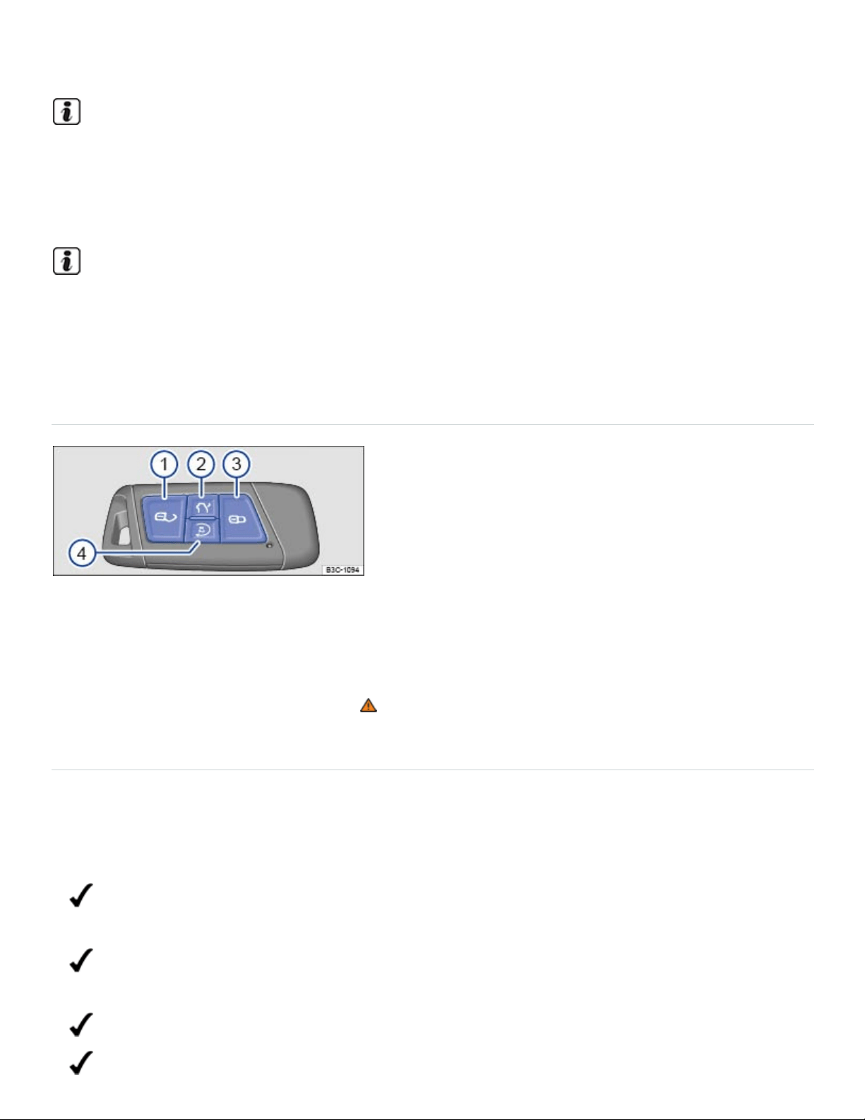
switch off the ignition.
After the engine has been switched off, the radiator fan in the engine compartment may keep run‐
ning for several minutes, or may start running after the vehicle has been parked for a while, even
if the ignition is switched off and the vehicle key has been removed. The radiator fan shuts off au‐
tomatically when the engine has cooled down enough.
If the ignition is switched on or the engine is running and the driver door is opened, a chime
sounds. The chime is also a reminder to switch off the engine and turn off the ignition before leav‐
ing and locking the vehicle from the outside.
Remote start feature
Fig.110Remote control vehicle key with remote start button.
In some vehicles, you can start the engine from outside of the vehicle with the remote start button
⇒Fig.110④ on the remote control vehicle key. This feature helps to cool or warm the passenger
compartment to about +68°F (+20°C) ⇒ .
Checklist
The following conditions must all be met at the same time to use the remote start feature.
Otherwise, the engine will not start, the remote start feature will stop, or the engine will
switch off automatically.
The vehicle must be ready to drive. For instance, there must be enough engine coolant Engine
coolant.
There must be enough fuel, and the low fuel indicator light must not have come on before the
engine was last switched off Indicator lights and fuel gauge.
The emergency flashers must not be switched on In an emergency.
The selector lever must be in Park (P) Automatic transmission selector lever.

All doors, the engine hood, and the trunk lid must be completely closed and locked.
The vehicle battery must be charged Vehicle battery.
The yellow engine Malfunction Indicator Light (MIL) must not have come on before the engine
was last switched off. Engine control and emission control system.
The remote start feature will not work if the yellow indicator light (MIL) comes on during a
remote start.
Using the remote start feature
Press the button on the remote control vehicle key 1 time ⇒Fig.110③ .
Within the next three seconds, press the button twice in a row ⇒Fig.110④ .
The turn signals flash each time you press a button and the parking lights turn on while the vehicle is
in remote start mode. When you open the driver door while the vehicle is in remote start mode, cer‐
tain warning and indicator lights come on, and a driver information message appears in the instru‐
ment cluster display.
If the remote start feature is not interrupted, the engine will run for about 10 minutes. A maximum of 2
remote starts in a row are possible, regardless of how long each one is allowed to run.
To be able to run 2 remote starts again, you must switch the ignition on and then off again ⇒Starting
and stopping the engine . All the remote start requirements must be met.
Climate control settings with remote start
The following climate control settings are automatically applied during remote start, unless you
change them from the controls inside the vehicle during a remote start.
Function activated Automatic setting
Seat ventilation (if equipped) Level 2, turns on at temperatures about +68 °F (+20 °C)
Seat heating (if equipped) Level 2, turns on at temperatures below +59 °F (+15 °C)
Outside mirror heating Turns on at temperatures below +68 °F (+20 °C)

Rear window defroster Turns on at temperatures below +39 °F (+4 °C)
Climatronic
Ventilation: AUTO
Temperature: +72 °F (+22 °C)
Manual air conditioning Ventilation: Last setting applied
You can use the air conditioning controls and the buttons for seat heating or ventilation (if equipped)
while the engine is in remote start mode to adjust settings. However, any changes will be replaced by
the automatic settings during the next remote start. It is not possible to change settings from the
Infotainment system ⇒Heating and air conditioning .
To change the automatic climate control settings, see an authorized Volkswagen dealer or an autho‐
rized Volkswagen Service Facility.
Remote start mode overrides any personalized settings. After the driver has taken over the vehicle,
personalized settings are reactivated.
Interrupting or stopping the remote start feature
With the vehicle key:
Press the button ⇒Fig.110④ or the panic button in the vehicle key to switch the engine off.
From inside the vehicle:
Turn on the emergency flashers.
OR: Press the starter button. Do not depress the brake pedal at the same time.
Driving after a remote start
To drive the vehicle when the engine is running in remote start mode, you must first depress the
brake pedal and press the starter button at the same time. During this process, the engine continues
to run ⇒Starting and stopping the engine .
WARNING

Improper use of the remote start feature can cause fire, burns and other serious injuries.
Always park the vehicle in a place that is vented to the outdoors and has a continuous ex‐
change of fresh, outside air.
Only use the remote start feature when no one is next to or inside the vehicle.
Always make sure that you can see the vehicle when the engine is running.
Never leave children, disabled persons, anyone who cannot help themselves, or pets in the
vehicle. The doors are locked when the engine is running with the remote start feature. Vehicle
occupants would be trapped in the vehicle in an emergency and rescue from the outside would
be delayed.
Never start the engine if children or animals are inside the vehicle. When the engine is run‐
ning, electrical equipment including electrical seat adjustment controls can be operated and
cause serious injuries.
Always make sure that the area where the engine runs in the remote start mode is well venti‐
lated. Never start the engine or let it run in a garage or in any other enclosed or confined area.
Engine exhaust contains carbon monoxide, a poisonous, colorless and odorless gas. Carbon
monoxide can impair the ability to drive, cause dizziness, nausea, unconsciousness, and even
death.
Never start the engine when the vehicle is covered with a protective cover. Hot vehicle compo‐
nents and exhaust could ignite the protective cover.
Never start the engine near combustible or explosive materials. The exhaust could ignite
flammable materials.
NOTE
Do not use the remote start feature if the yellow engine Malfunction Indicator Light (MIL)
has come on, smoke or unusual smells come from the vehicle, an unusual or unexpected op‐
erating condition occurs and the condition has not been diagnosed and corrected. Please see
an authorized Volkswagen dealer or authorized Volkswagen Service Facility.
Remote start is possible when one or more windows are open. Always remember that unau‐
thorized access to the vehicle through open windows is possible when the engine is running in
remote start mode. Always make sure that all of the windows are securely closed to help pre‐
vent unauthorized access to the vehicle, its features and contents.
Using the remote start feature can increase fuel consumption and drain the vehicle battery.

Use of the remote start feature may be regulated or prohibited in some areas. In some areas you
may be required to be able to see the vehicle when it is running in remote start mode. Please in‐
form yourself about state and local requirements that may apply and be sure to follow them when
using the remote start feature.
Various vehicle functions, such as the low beam headlights and the windshield wipers, are dis‐
abled when the engine is running during a remote start.
Electronic immobilizer
The immobilizer helps to prevent the engine from being started and driven with an unauthorized vehi‐
cle key.
There is a microchip inside the vehicle key. The chip deactivates the immobilizer automatically when
an authorized vehicle key is inserted into the ignition switch or the starter button is pressed.
The electronic immobilizer is automatically activated when the remote control vehicle key is pulled out
of the ignition switch. On vehicles with Keyless Access, the vehicle key must be outside the vehicle
⇒Unlocking or locking the vehicle with Keyless Access .
The engine can therefore only be started with an authorized and correctly coded genuine Volkswagen
vehicle key. Coded vehicle keys are available from authorized Volkswagen dealers, authorized
Volkswagen Service Facilities, and from certain independent repair facilities and locksmiths who are
qualified to make these vehicle keys ⇒Vehicle key set .
If an unauthorized vehicle key is used, a message may appear in the instrument cluster display. The
vehicle cannot be operated with this key.
Using genuine Volkswagen keys helps minimize the risk of malfunctions.
A Declaration of Compliance with the United States FCC and Industry Canada regulations is on
⇒Declaration of Compliance, Telecommunications and Electronic Systems .
Applicable only in the United States

Tips and troubleshooting
Fig.111Hold the remote control vehicle key to the right of the steering column: Emergency starting
feature.
Engine control malfunction
The yellow indicator light comes on.
Have the engine checked immediately by an authorized Volkswagen dealer or authorized
Volkswagen Service Facility.
Engine speed (rpm) limited
The yellow indicator light comes on.
Engine speed (rpm) automatically limited to help prevent the engine from overheating.
Briefly take your foot off the accelerator.
The limited engine speed is shown in the instrument cluster.
Once the engine is no longer at a critical temperature, the engine speed limit is increased.
and Engine speed limited
The yellow indicator lights come on.
The engine speed is limited due to a malfunction in the engine management system

Make sure that the engine speed does not exceed the engine speed displayed, for example, when
downshifting.
Have the engine checked immediately by an authorized Volkswagen dealer or authorized
Volkswagen Service Facility.
If you use the wrong vehicle key or cannot remove the key from the ignition switch
Press the release button on the transmission selector lever and release. The vehicle key can now
be removed.
If the engine does not stop
If the engine does not switch off by briefly pressing the starter button, emergency shut-off is
necessary:
Press the starter button twice within 3seconds.
OR: Press and hold the button longer than 1second ⇒ .
The engine switches off automatically.
If the engine does not start
If an authorized remote control vehicle key is in the passenger compartment but is not detected, the
remote control vehicle key battery may be weak or dead. You can still start the engine using the
emergency start feature.
Make sure the selector lever is in the Park (P) position.
Press and hold the brake pedal.
Hold the remote control vehicle key to the right of the steering column trim immediately after
pressing the starter button ⇒Fig.109 or .
The ignition automatically switches on and the engine starts.
If the engine cannot be started with the remote start feature
If at least one of the following conditions apply, the remote start feature will not start the engine:
The vehicle is unlocked.
A vehicle door, the engine hood, or the trunk lid is open.
The selector lever is not in park (P).
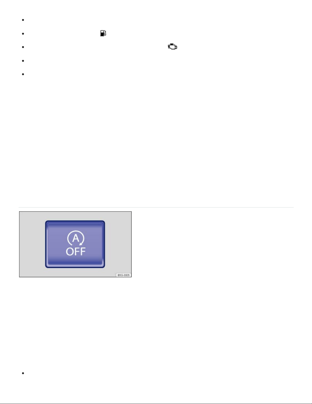
The brake or gas pedal is pressed.
The low fuel indicator light is on.
The yellow engine Malfunction Indicator Light (MIL) is on.
The 12Volt vehicle battery level is too low.
The emergency flashers are on.
Make sure that all of the necessary requirements for a remote start are met and restart the engine, if
necessary ⇒Remote start feature .
The engine does not start in cold weather
The engine does not start or starts only with difficulty.
Gasoline with ethanol has poor cold-starting properties and it is therefore not easy to start the engine
at low outside temperatures ⇒Starting the engine .
If the outside temperature falls below +14°F (-10°C), use a gasoline with a higher octane rating
(ROZ95).
Start-stop system
Fig.112In the upper center console: Button for the start-stop system.
The start-stop system automatically switches the engine off when the vehicle is coming to a stop and
when it is not moving. When required, the engine restarts automatically.
Switching the start-stop system on
The feature is automatically activated every time the ignition is switched on. The instrument cluster
display shows current status information.
Press and hold the brake pedal to stop. The engine switches off when the vehicle is not moving.

Take your foot off the brake pedal or depress the accelerator to restart the engine.
Indicator lights
Start-stop available, automatic engine stop is active.
Start-stop not available OR Start-stop has switched the engine on automatically.
Requirements for the engine to automatically switch off
The driver must be wearing their safety belt.
The driver door must be closed.
The engine hood must be closed.
The engine must have reached minimum operating temperature.
For vehicles with Climatronic: The temperature inside the vehicle must be within the pre-set tem‐
perature range and the humidity must not be too high.
The windshield defrost function must not be switched on.
The vehicle battery must be sufficiently charged.
The vehicle battery temperature must not be too low or too high.
The vehicle must not be on a steep incline.
The vehicle must not be in reverse gear.
The Park Assist system must not be active.
The vehicle must not be in offroad mode.
Requirements for the engine to automatically restart
The engine may restart automatically under the following conditions:
If the vehicle interior becomes very hot or very cold.
If the vehicle rolls forward or backward.
If the vehicle battery voltage lowers.
If the steering wheel is moved.
As a general rule, the engine restarts automatically when the system detects that it is necessary.
Conditions that require a manual engine start

You must restart the engine manually if:
The driver door is open.
The engine hood is open.
The driver safety belt is unbuckled.
Manually deactivating and activating the start-stop system
Press the button in the upper center console to deactivate the system ⇒Fig.112 .
Press the button again to activate the system.
Every time the button is pressed, the start-stop system status is shown in the instrument cluster
display.
If start-stop switches the engine off, it will restart if you press the button.
Always manually switch off start-stop when driving through water.
WARNING
Never stop the engine before the vehicle has come to a complete stop. You can lose control of
the vehicle, crash, and be seriously injured.
The airbags and safety belt pretensioners will not work when the ignition is switched off.
The brake booster does not work when the engine is not running. More brake pedal pressure
will be needed to stop the vehicle.
The power steering system does not work when the engine is not running, and you will need
more force to steer the vehicle.
Never remove the key from the ignition switch or turn off the ignition with the starter button
while the vehicle is moving or rolling to a stop. The electronic steering column could suddenly
lock, you would not be able to steer, and you could lose control of the vehicle, crash, and seri‐
ously injure yourself and others.
Switch the start-stop system off before working in the engine compartment.
WARNING
Failure to heed warning lights and instrument cluster text messages can result in a collision and
serious personal injury.

Never ignore warning lights or text WARNINGS.
Always stop the vehicle as soon as it is safe to do so.
Whenever stalled or stopped for repair, move the vehicle a safe distance off the road, turn on
the emergency flashers, stop the engine, and use other warning devices to warn approaching
traffic.
NOTE
The vehicle battery may be damaged if the start-stop system is active for a long time in very hot
outside temperatures.
If the outside temperature is above about +100°F (+38°C), the Start-stop system may switch off
automatically.
In certain situations it may be necessary to manually restart the engine. A text message will ap‐
pear in the instrument cluster display.
In vehicles with Driving Mode Selection, the start-stop system is automatically activated in the
Eco driving mode.
Always manually deactivate the start-stop system when driving through water.
Automatic transmission
Automatic transmission selector lever
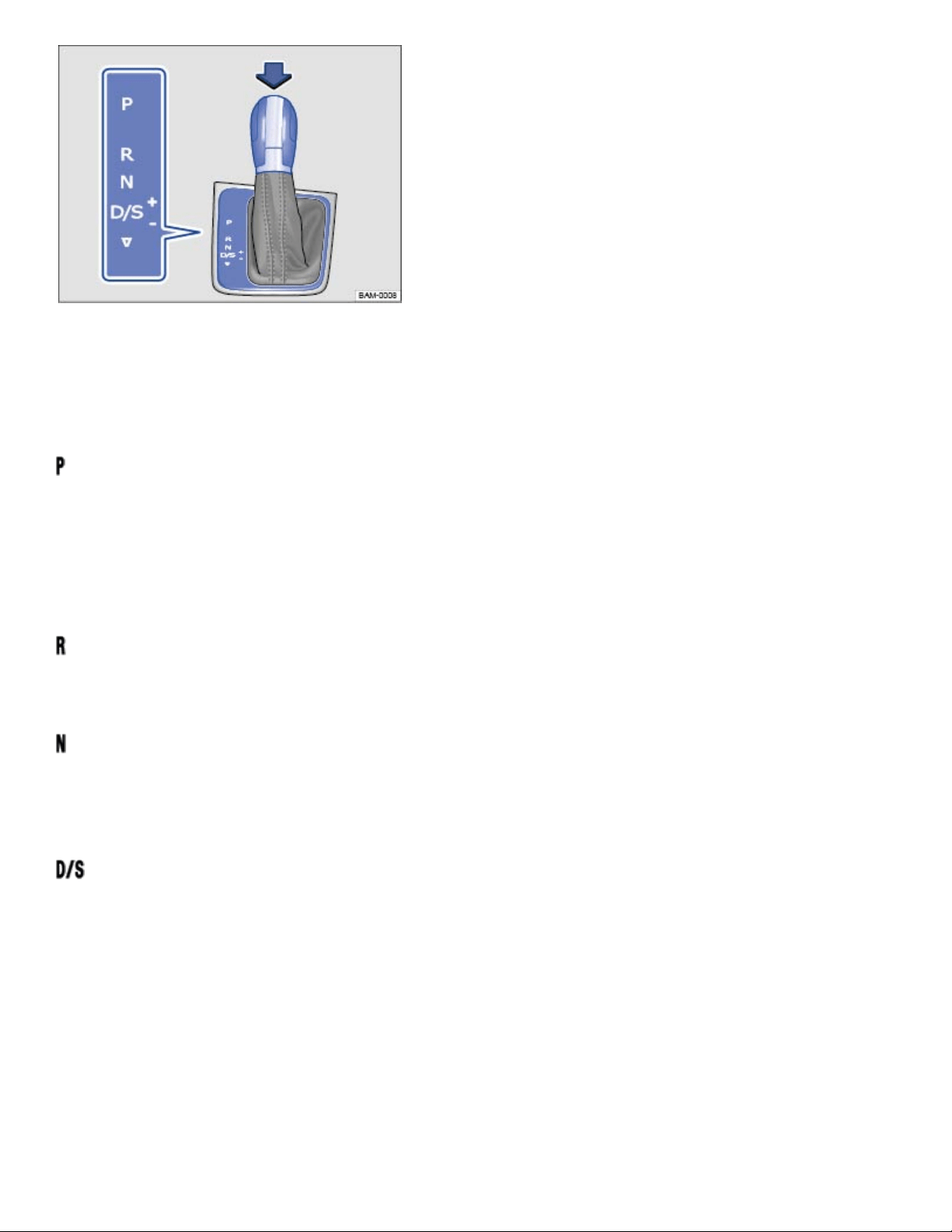
Fig.113Automatic transmission selector lever with shift lever release button (arrow).
If the ignition is switched on, the current selector lever setting is shown in the instrument cluster
display.
– Park
The drive wheels are mechanically locked. Select only when the vehicle is not moving.
To change the selector lever position, switch on the ignition (if it is off) and then press the selector
lever release button while holding down the brake pedal.
– Reverse
The reverse gear is engaged. Shift into Reverse only when the vehicle is not moving.
– Neutral
Transmission is in neutral position. No power is transmitted to the wheels and no engine braking is
available.
– Drive or Sport Drive
Standard driving position D: All forward gears shift up and down automatically. The transmission
shifts as needed depending on engine load, individual driving style, and vehicle speed.
Sport driving position S: All forward gears automatically upshift later and downshift earlier than in
position D to take full advantage of the engine's power reserves. The transmission shifts as needed
depending on engine load, individual driving style, and vehicle speed.
Switch between Drive (D) and Sport drive (S) by pulling the selector lever once to the rear from gear
position D/S⇒Fig.113 .

The selector lever always returns to gear position D/S. It is possible to access Tiptronic selection from
gear position D/S when either Drive (D) or Sport drive (S) is active ⇒Shifting with Tiptronic .
Tiptronic mode: In Tiptronic mode, M may appear in the instrument cluster along with the current
Tiptronic gear.
Automatic Shift Lock (ASL)
The Automatic Shift Lock (ASL) in park (P) and neutral (N) prevents drive positions from being en‐
gaged inadvertently, which would cause the vehicle to move.
To release the ASL, depress and hold the brake pedal with the ignition switched on. Press the release
button on the selector lever at the same time (arrow) ⇒Fig.113 .
The ASL is not engaged if the selector lever is moved quickly through neutral (N) (e.g., when shifting
from reverse (R) to drive (D/S)). This makes it possible to rock the vehicle backwards and forwards if
it is stuck in snow or mud. The ASL engages automatically if the brake pedal is not depressed, the se‐
lector lever is in neutral (N) for more than about 1second, and the vehicle is traveling no faster than
about 3mph (5km/h).
WARNING
Moving the selector lever to the wrong position can cause loss of vehicle control, a collision, and
serious personal injury.
Never accelerate when moving the selector lever.
When the engine is running and a drive position is engaged, the vehicle will start to move as
soon as the brake pedal is released.
Never shift into Reverse (R) or Park (P) when the vehicle is moving.
WARNING
Unintended vehicle movement can cause serious personal injury.
Never get out of the driver's seat while the engine is running, especially when the transmission
is in a drive gear. If you must leave your vehicle while the engine is running, always set the
parking brake and shift the transmission to Park (P).
Never leave the vehicle in Neutral (N). It will roll down hills, whether the engine is running or
not.
®
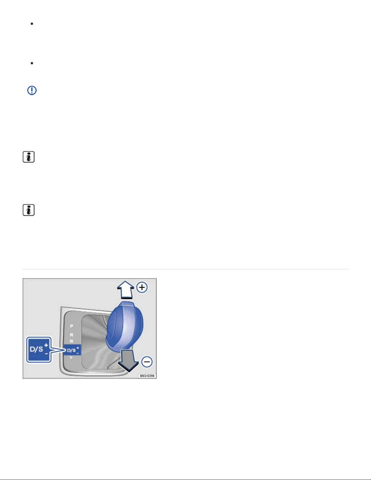
When the engine is running and a drive gear - Drive or Sport Drive (D/S) or Reverse (R) - has
been selected, press and hold the brake pedal to keep the vehicle from moving. The vehicle
may creep and move forward or backward even if the engine is idling slowly.
Never shift into Reverse (R) or Park (P) when the vehicle is moving.
NOTE
Even though the transmission is in Park (P), the vehicle may move a couple of inches (a few cen‐
timeters) forwards or backwards if you take your foot off the brake pedal after stopping the vehi‐
cle without first setting the parking brake.
If the selector lever is moved into Neutral (N) by mistake when the vehicle is moving, take your
foot off the accelerator pedal. Wait until the engine speed has dropped to idle speed before mov‐
ing the selector lever into a drive gear.
Leaving the selector lever for a long period of time in any position other than Park (P) when the
ignition is switched off can drain the 12 Volt vehicle battery.
Shifting with Tiptronic
Fig.114Selector lever in Tiptronic position.
Tiptronic lets you upshift and downshift manually with the automatic transmission. When Tiptronic
mode is used, the transmission stays in the current gear and does not upshift or downshift automati‐
cally unless the transmission senses a situation where upshifting or downshifting is necessary to keep
the engine from over- or under-revving.
®

Using Tiptronic with the selector lever
Push the selector lever sideways to the right from the D/S position into the Tiptronic position ⇒ .
Briefly push the selector lever forward⊕ to upshift into a higher gear or backward
㊀
to downshift
into a lower gear ⇒Fig.114 .
It is not necessary to press the release button on the selector lever when upshifting or downshifting
with Tiptronic.
NOTE
During acceleration, the transmission will shift automatically into the next higher gear before
reaching maximum engine speed (rpm).
If you use Tiptronic to shift into a lower gear, the transmission will downshift only when doing
so will not over-rev the engine.
Driving with automatic transmission
All forward gears shift up and down automatically.
Driving downwards on hills
The steeper the slope, the lower the gear that must be selected. Lower gears increase the braking ef‐
fect of the engine. Never coast downhill in neutral (N).
Reduce speed.
Switch to Tiptronic mode by moving the selector lever from Drive or Sport Drive (D/S) to the right
into the Tiptronic position ⇒Shifting with Tiptronic .
Downshift by pulling the selector lever back briefly (-).
Driving up hills
The steeper the upward slope, the lower the gear that must be selected.
If you stop and start up again when going uphill, the Hill Start Assist feature can help prevent the vehi‐
cle from rolling backwards as long as the engine is running ⇒Hill Start Assist (Hill Hold) .
If you stop on a hill with the vehicle in gear, you must depress the brake pedal or engage the parking
brake to keep the vehicle from rolling. Do not release the brake pedal or the parking brake until the
vehicle has started to move forward ⇒ .
®

Kick-down acceleration
The kick-down feature permits maximum acceleration when the selector lever is in the Drive or Sport
Drive (D/S) position or in Tiptronic mode.
If you push the accelerator all the way down, the vehicle will automatically downshift, depending on
vehicle speed and engine speed (rpm). This feature lets you take advantage of the full acceleration
capacity of the vehicle ⇒ .
With kick-down acceleration, the transmission will stay in the current gear longer and not upshift until
the engine reaches maximum rpm.
WARNING
Rapid acceleration can cause skidding and loss of traction, especially on slippery roads, resulting
in a loss of vehicle control, collisions, and serious personal injury.
Only use the kick-down feature or fast acceleration if visibility, weather, road, and traffic condi‐
tions permit and other drivers will not be endangered by your driving and the vehicle's
acceleration.
Always adapt your driving to the traffic flow.
Note that the drive wheels can spin and the vehicle can swerve when ASR is switched off, es‐
pecially when the road is slippery.
Once you have accelerated, switch ASR back on again.
NOTE
When stopping on hills with the transmission in a drive gear, do not use the accelerator to help
prevent the vehicle from rolling backwards. This can cause the automatic transmission to over‐
heat and be damaged.
Never let the vehicle coast or roll down a hill in Neutral (N), especially when the engine is not
running. The transmission will not be lubricated and will be damaged.
Tips and troubleshooting
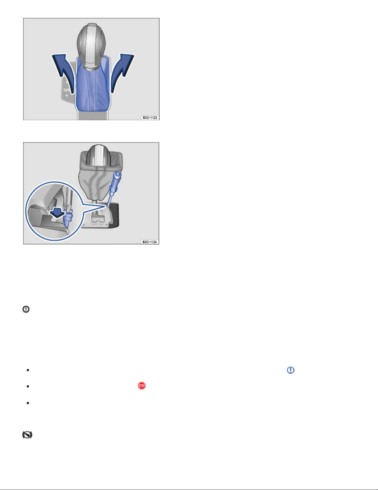
Fig.115Removing the selector gate cover.
Fig.116Releasing the selector lever lock.
When the ignition is switched on, several warning and indicator lights come on briefly for a function
check. They go out after a few seconds.
Transmission overheating
The yellow indicator light comes on.
An acoustic warning may also sound. A text message may also appear in the instrument cluster.
Shift the selector lever to the P position and let the transmission cool down ⇒ .
If the warning does not turn off, do not continue driving!
See your authorized Volkswagen dealer for assistance. Otherwise, serious clutch or transmission
damage could result.
If the engine does not start
The green indicator light comes on.

The brake pedal is not depressed, for example, while trying to select another drive gear.
Depress the brake pedal to select another driver gear.
Also refer to electronic parking brake ⇒Electronic parking brake .
If the vehicle does not move
The green indicator light flashes.
The release button in the selector lever did not engage.
Engage the selector lever release button ⇒Automatic transmission selector lever .
If the vehicle does not shift
The green indicator light flashes along with a text message in the instrument cluster display.
In rare cases, the Automatic Shift Lock (ASL) may not engage.
The drive is then deactivated to prevent the vehicle from accidentally moving..
Depress and then release the brake pedal. Try to engage the ASL again.
OR: Shift the selector lever to Neutral (N) or Park (P), then try to select a drive position again.
Emergency release for the selector lever lock
If the power supply fails (due to a dead vehicle battery, for example) and the vehicle has to be pushed
or towed, the emergency release must be used to move the selector lever to neutral (N). You will
need the screwdriver from the vehicle tool kit to release the selector lever ⇒Vehicle tool kit .
The emergency release is under the selector gate cover on the right side when viewed in the driving
direction.
Set the parking brake. If the parking brake cannot be set, you must find another way to help pre‐
vent the vehicle from moving ⇒ .
Switch off the ignition.
Carefully pull upward on the cover around the selector lever ⇒Fig.115 .
Slip the cover up and over the selector lever.

With the screwdriver from the vehicle tool kit, carefully push the colored release lever ⇒Fig.116
(arrow) towards the rear of the vehicle and hold it in this position.
Press the release button in the selector lever handle and shift the selector lever to neutral (N).
Carefully press the selector lever cover back in place, making sure that the electrical wiring stays
in the correct position and is not pinched or damaged.
Emergency shift program
If the automatic transmission is operating in the emergency shift program, the yellow indicator light
comes on along with a text message in the instrument cluster display. The selector lever position may
still be displayed, depending on the malfunction. The text message disappears after a few seconds,
but the yellow indicator light stays on until the malfunction is corrected.
Have the automatic transmission checked immediately by an authorized Volkswagen dealer or autho‐
rized Volkswagen Service Facility.
The vehicle does not move even though a drive position is selected with the selector lever
If the vehicle does not move in the desired direction, the system may not have engaged the drive po‐
sition correctly.
Press the brake pedal and select the drive position again.
If the vehicle still does not move in the desired direction, there is a system malfunction. See your
authorized Volkswagen dealer or authorized Volkswagen Service Facility for assistance to have
the system checked.
WARNING
Never shift the transmission out of Park (P) without first firmly applying the parking brake.
Otherwise, the vehicle can start to roll unexpectedly, especially on hills or inclines, and cause an
accident and serious injuries.
WARNING
Failure to heed warning lights and instrument cluster text messages can result in a collision and
serious personal injury.
Never ignore warning lights or text WARNINGS.
Always stop the vehicle as soon as it is safe to do so.

Whenever stalled or stopped for repair, move the vehicle a safe distance off the road, turn on
the emergency flashers, stop the engine, and use other warning devices to warn approaching
traffic.
NOTE
Even with the selector lever is in Neutral (N), the automatic or DSG transmission will be damaged
if the vehicle is towed (or you let it coast) for an extended period or at high speed with the engine
shut off.
NOTE
As soon as you get any of these warnings about transmission overheating, you must either
park the vehicle in a safe place or drive faster than 12mph (20km/h).
If the text message and acoustic warning repeat themselves every 10seconds or so, you must
park the vehicle in a safe place as soon as you can safely do so and stop the engine. Let the
transmission cool down.
To help prevent damage to the transmission, do not drive the vehicle again until the acoustic
warning has stopped. As long as the engine is overheated, avoid stop and start driving and
avoid low speeds (walking pace).
Hill Start Assist (Hill Hold)
Some vehicles are equipped with Hill Start Assist (Hill Hold) , a feature that helps keep the vehicle
from rolling backwards when starting out on a hill, for example after stopping at a traffic light. You
don't have to apply and release the parking brake while depressing the accelerator. For Hill Start
Assist to work, the engine must be on and the vehicle must be in Drive or Sport (D/S) or Reverse (R)
and you must use the foot brake to hold the vehicle before starting to move.
Hill Start Assist keeps the brake applied for almost 2seconds with the same force you used to pre‐
vent the vehicle from moving. This gives you time to take your foot off the brake and gently depress
the accelerator to get the vehicle moving again. If you do not depress the accelerator pedal and get
the vehicle moving again within this time, the brakes will release and the vehicle will roll downhill.
Furthermore, if any requirement for engaging Hill Start Assist is no longer met while the vehicle is
stopped, Hill Start Assist disengages and the brakes are automatically released and will no longer
hold the vehicle.
Hill Start Assist is activated automatically when the following points are met at the same time:

The vehicle must be stopped on an incline with the foot brake or parking brake.
The engine must be running smoothly.
All 4 wheels must have sufficient contact with the road and the vehicle may not be ramped.
The vehicle must be in Drive or Sport Drive (D/S) if headed up a hill or Reverse (R) if backing up a
hill, and the foot brake must be depressed to keep the vehicle from moving.
To drive off, take your foot off the brake pedal and gently depress the accelerator within 2 seconds.
Hill Start Assist is immediately deactivated:
If any requirement listed above is no longer met.
If the engine stalls or is switched off.
If the transmission is in Neutral (N).
If the driver door is opened.
If a tire does not have enough road contact (such as when the vehicle is tipped or at an angle).
WARNING
The intelligent technology of Hill Start Assist cannot overcome the laws of physics. Never let the
increased convenience provided by Hill Start Assist tempt you into taking risks.
Hill Start Assist cannot hold the vehicle in all hill start situations (for example, if the surface is
icy or slippery).
Hill Start Assist can only help keep the vehicle from moving for less than 2seconds. After that,
the brakes will be released and the vehicle can roll down the hill.
Hill Descent Control
When displayed in green: Hill Descent Control is active.
When displayed in grey: Hill Descent Control is not active. System is switched on, but does
not regulate.
Some vehicles are equipped with Hill Descent Control. Hill Descent Control helps the driver on steep
downhill grades by actively braking all four wheels to limit the speed when driving forward or revers‐
ing on steeper slopes. The wheels do not lock as the ABS stays active ⇒ .

If you enter a downhill slope traveling at a speed below 18mph (30km/h), the vehicle speed will be
limited to a speed between about 1-18mph (2-30km/h). The driver can use the accelerator pedal and
the brakes to adjust the speed within this range. The feature is interrupted and restarted each time.
One requirement for speed regulation is that the tires must have a sufficiently good grip on the ground
underneath. For example, Hill Descent Control cannot work properly on icy slopes or on slopes with
an oily road surface.
An indicator light comes on in the instrument cluster display whenever Hill Descent Control is
active.
Hill Descent Control regulates the brakes only when certain requirements are met.
Hill Descent Control regulates automatically if all of the following conditions apply:
The vehicle's engine is running.
The vehicle speed is under 18mph (30km/h) (The indicator light is on in the instrument cluster
display).
The driver does not press the gas or brake pedals.
Hill Descent Control switches off if the vehicle goes faster than 18mph (30km/h), you accelerate or
step on the brake, or if the downhill grade drops below 5%. Hill Descent Control begins regulating
speed again the next time the requirements are met.
WARNING
The intelligent technology of Hill Descent Control cannot overcome the laws of physics. Never let
the increased convenience provided by Hill Descent Control tempt you into taking risks.
Always adjust your speed, driving style, and the distance you keep between you and the vehi‐
cles ahead of you to the road, traffic, weather, and visibility conditions.
Unintended vehicle movement can cause serious personal injury.
Hill Descent Control is not a substitute for careful and attentive driving.
Hill Descent Control cannot slow the vehicle down in all situations (for example, if the ground
is slippery or icy).
Always be prepared to take full control of the vehicle at all times.
WARNING

Always be ready to apply the brakes. Otherwise accidents and injuries can occur.
Hill Descent Control is merely a driving aid and cannot always slow the vehicle down enough
on all downhill grades.
The vehicle may pick up speed despite the use of Hill Descent Control.
The Hill Descent Control also works when backing down a hill.
Steering
Steering system information
To help prevent vehicle theft, you should always make sure the steering column is locked before leav‐
ing the vehicle.
The steering system
Your vehicle is equipped with an electromechanical power steering system. The power steering works
only when the engine is running.
The electromechanical power steering system automatically adjusts to driving speed, steering torque,
and the steering angle of the wheels. It delivers extra steering force only when you are actually turn‐
ing the wheels.
In vehicles with 4MOTION Active Control, the selected driving mode can affect the steering behavior
⇒4MOTION Active Control .
Electronic steering column lock (vehicles with Keyless Access)
In vehicles with a starter button, the steering column is locking electronically:
Bring the vehicle to a stop and shift the transmission to Park (P).
Switch off the ignition and then open the driver door. The steering column is locked.
If the steering column should not be locked, first open the driver door, and then switch off the ignition.
To then lock the steering column, lock the vehicle with the vehicle key bit, the emergency key, or via
the sensors in the door handles.

Mechanical steering column lock (vehicles without Keyless Access)
In vehicles with an ignition switch, the steering column is locked mechanically:
Bring the vehicle to a stop and shift the transmission to Park (P).
Remove the vehicle key from the ignition switch.
Turn the steering wheel slightly until the steering column lock clicks into place.
To disengage the steering column lock, insert the vehicle key into the ignition switch. Turn the steer‐
ing wheel slightly to take pressure off the steering column lock. Hold the steering wheel in this posi‐
tion and turn the ignition switch.
Power steering
Power steering automatically adjusts to driving speed, steering torque, and the steering angle of the
wheels. Power steering works only when the engine is running.
If power steering is reduced or lost completely, it will be much harder to steer and control the vehicle.
Counter-steering assistance
Counter-steering assistance makes it easier for the driver to control the vehicle in difficult situations.
For example, if you have to brake hard on a surface that provides uneven traction, counter-steering
assistance detects this situation and helps the driver counter-steer with additional steering power ⇒
.
WARNING
Turning the steering wheel is very hard when the power steering system is not working. This
makes it harder to steer and control the vehicle.
Power steering works only when the engine is running.
Never let the vehicle coast with the engine switched off.
Never remove the key from the ignition switch or turn off the ignition with the starter button
while the vehicle is moving or rolling to a stop. The electronic steering column could suddenly
lock, you would not be able to steer, and you could lose control of the vehicle, crash, and seri‐
ously injure yourself and others.
WARNING

The counter-steering assistance in ESC can do no more than help the driver steer in difficult situ‐
ations. The driver must still control the vehicle. The vehicle does not steer by itself with this
feature!
NOTE
If the ignition is off, the steering column lock will engage and the vehicle cannot be steered. For
this reason, you must leave the ignition on when going through an automatic car wash, for exam‐
ple, so that the wheels will still steer.
NOTE
When towing the vehicle with a tow bar or tow rope, always leave the ignition on to prevent the
steering wheel from locking, and so that the turn signals, horn, windshield wipers, and window
washer system can be used.
Tips and troubleshooting
When the ignition is switched on, several warning and indicator lights come on briefly for a function
check. They go out after a few seconds.
Power steering malfunction
The red warning light comes on or flashes.
The electronic steering column lock is malfunctioning.
Stop! Contact your authorized Volkswagen dealer or an authorized Volkswagen Service Facility
for assistance.
When the red warning light comes on and stays on, the power steering may be reduced or lost
completely. It may be much harder to steer and control the vehicle.
When the red warning light flashes, The steering column lock cannot be unlocked.
Steering malfunction
The warning light lights up or flashes yellow.

When the warning light comes on and stays on, restart the engine, and slowly drive a short dis‐
tance. If the warning light stays on, have the steering checked immediately by an authorized
Volkswagen dealer or an authorized Volkswagen Service Facility.
Turn the steering wheel back and forth.
Switch the ignition off and then switch it on again.
Heed any messages shown in the instrument cluster display, if applicable.
Do not drive any farther if the warning light continues to flash after you switch on the ignition.
Contact your authorized Volkswagen dealer or an authorized Volkswagen Service Facility for
assistance.
WARNING
Failure to heed warning lights or other warnings can result in a collision and serious personal
injury.
Never ignore warning lights or text WARNINGS.
Always stop the vehicle as soon as it is safe to do so.
Whenever stalled or stopped for repair, move the vehicle a safe distance off the road, turn on
the emergency flashers, switch off the engine, and use other warning devices to warn ap‐
proaching traffic.
Park the vehicle where no part of the hot catalytic converter and exhaust system can come
into contact with flammable materials under the vehicle, such as dry grass, brush, spilled fuel,
etc.
4MOTION Active Control
Introduction to the subject
In this chapter you will find information on the following subjects:
⇒Driving Mode Selection
⇒Adjusting the Custom driving modes
⇒Tips and troubleshooting
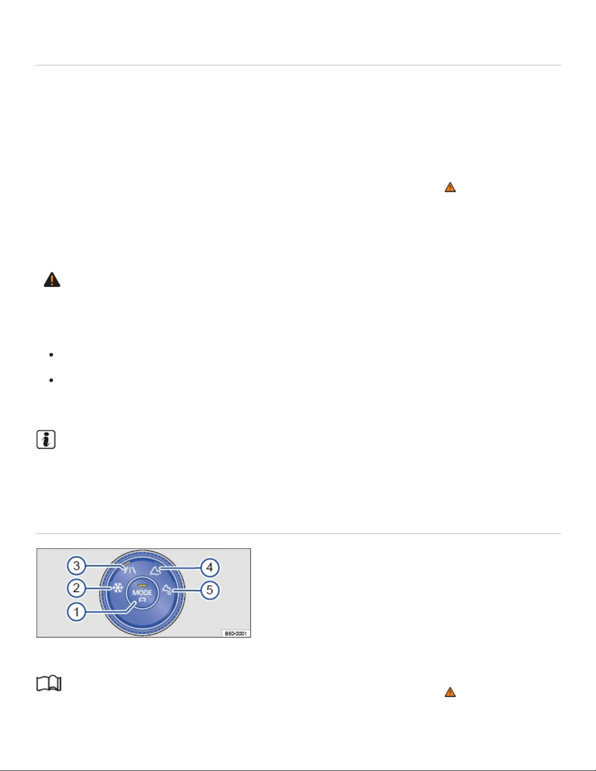
⇒Offroad display
Depending on equipment, different driving modes can be selected. The effect on the vehicle settings
in the individual on-road driving modes depends on vehicle equipment.
Vehicles with all-wheel drive have on-road driving modes and offroad driving modes ⇒Driving Mode
Selection .
The driving mode can be changed while the vehicle either is or is not moving ⇒ . After selecting an
driving mode, the vehicle settings (excluding engine settings) are switched to the new driving mode
immediately. When traffic conditions allow, briefly take your foot off the accelerator to activate the
newly selected driving mode for the engine.
WARNING
Driving on today's roads demands the full attention of the driver at all times. Driver distraction
causes accidents, collisions and serious personal injury!
Never let yourself be distracted when setting, adjusting, or using the Infotainment system.
Always drive attentively and responsibly. Use the Infotainment system only if road, traffic, and
weather conditions permit and you will not be distracted from your driving.
Certain settings are automatically saved by the driver personalization feature ⇒Driver
Personalization .
Driving Mode Selection
Fig.117In the lower center console: 4MOTION Active Control.
Read and follow the introductory information and safety information first⇒ Introduction to the
subject

Key to ⇒Fig.117 :
Driving Mode Selection button: Select an on-road driving mode or open the menu in the
Infotainment system..
Snow
On-road
Off-road
Custom off-road
Selecting a 4MOTION Active Control driving mode
Switch on the ignition.
Turn the knob until the desired driving mode lights up ⇒Fig.117 . The selected driving mode ap‐
pears in the Infotainment system.
OR: Press the Driving Mode Selection button ⇒Fig.117 ① or tap the function key for the se‐
lected driving mode in the Infotainment system display.
To switch to an on-road driving mode, press the Driving Mode Selection button, and then tap the
function key for the desired on-road driving mode in the Infotainment system display.
Press the function key i to show additional information about the selected driving mode.
Some settings for the selected driving mode may stay set even after the ignition is switched off, and
other settings may return to Normal mode.
If one of the driving modes Snow, Offroad, or Custom Offroad was the last selected driving mode,
the most recently active on-road driving mode will activate if the ignition stays switch off for an ex‐
tended period.
If the Sport or Eco mode is active, the automatic transmission will return to the Normal driving mode
when the ignition is switched off.
Sport: select the Sport driving profile again.
OR: briefly pull the selector lever back into the Sport (S) position ⇒Automatic transmission
Eco: select the Eco driving profile again.
Driving mode characteristics

Snow ②: The driving mode Snow provides better accelerator sensitivity on icy or snow-covered
roads. In addition, the lane holding when cornering and the power in straight driving are also im‐
proved. The dynamic of the Adaptive Cruise Control is restricted.
Onroad ③: The driving mode Onroad can be extended with the modes Eco, Normal, Sport, and
Custom.
Offroad ④: In Offroad mode, vehicle acceleration is more sensitive in off-road terrain. Shift points
may change. In the Offroad mode, the Hill Start Assist and Hill Descent Control are active.
Custom Offroad ⑤: The driving mode Custom Offroad allows more settings to be made in of‐
froad mode. You can select individual characteristics for various systems while still enjoying the
advantages of the offroad mode. The indicator light appears in the instrument cluster.
Eco: Sets the vehicle in a low consumption mode and supports the driver with more eco-friendly
driving. The Eco mode affects the climate control and ACC system.
Normal: Balanced setting for everyday use.
Sport: Gives the vehicle a sporty driving feel and is suited for a sporty driving style. The transmis‐
sion is automatically switched into the Sport driving position (S).
Custom: Individual systems can be adjusted to suit your personal requirements ⇒Adjusting the
Custom driving modes .
WARNING
Changing the driving mode can alter vehicle handling. Never allow 4MOTION Active Control to
tempt you into taking extra risks.
Always adjust your speed and driving style to road, traffic, weather, and visibility conditions.
WARNING
Failure to heed warning lights and instrument cluster text messages can result in a collision and
serious personal injury.
Never ignore warning lights or text WARNINGS.
Always stop the vehicle as soon as it is safe to do so.
NOTE
Failure to heed warning lights or text WARNINGS can result in vehicle damage.

Adjusting the Custom driving modes
Read and follow the introductory information and safety information first⇒ Introduction to the
subject
Adjusting the Custom on-road driving mode
Switch on the ignition.
Turn the 4MOTION Active Control knob to the Onroad driving mode ⇒Fig.117③ .
Tap the Custom function key in the Infotainment system display or toggle to Custom using the
Driving Mode Selection button.
Tap the Adjust function key to open the Custom menu.
Adjusting the Custom offroad driving mode
Switch on the ignition.
Turn the knob until the Custom Offroad icon lights up ⇒Fig.117⑤ .
Tap the Adjust function key on the Infotainment system screen to open the Custom offroad
menu.
When the traffic condition allows, briefly take your foot off the accelerator to activate engine set‐
tings for the newly selected Custom offroad driving mode.
WARNING
Driving on today's roads demands the full attention of the driver at all times. Driver distraction
causes accidents, collisions and serious personal injury!
Never let yourself be distracted when setting, adjusting, or using the Infotainment system.
Always drive attentively and responsibly. Use the Infotainment system only if road, traffic, and
weather conditions permit and you will not be distracted from your driving.
Tips and troubleshooting
Read and follow the introductory information and safety information first⇒ Introduction to the
subject
The transmission cannot be switched into position Sport (S)
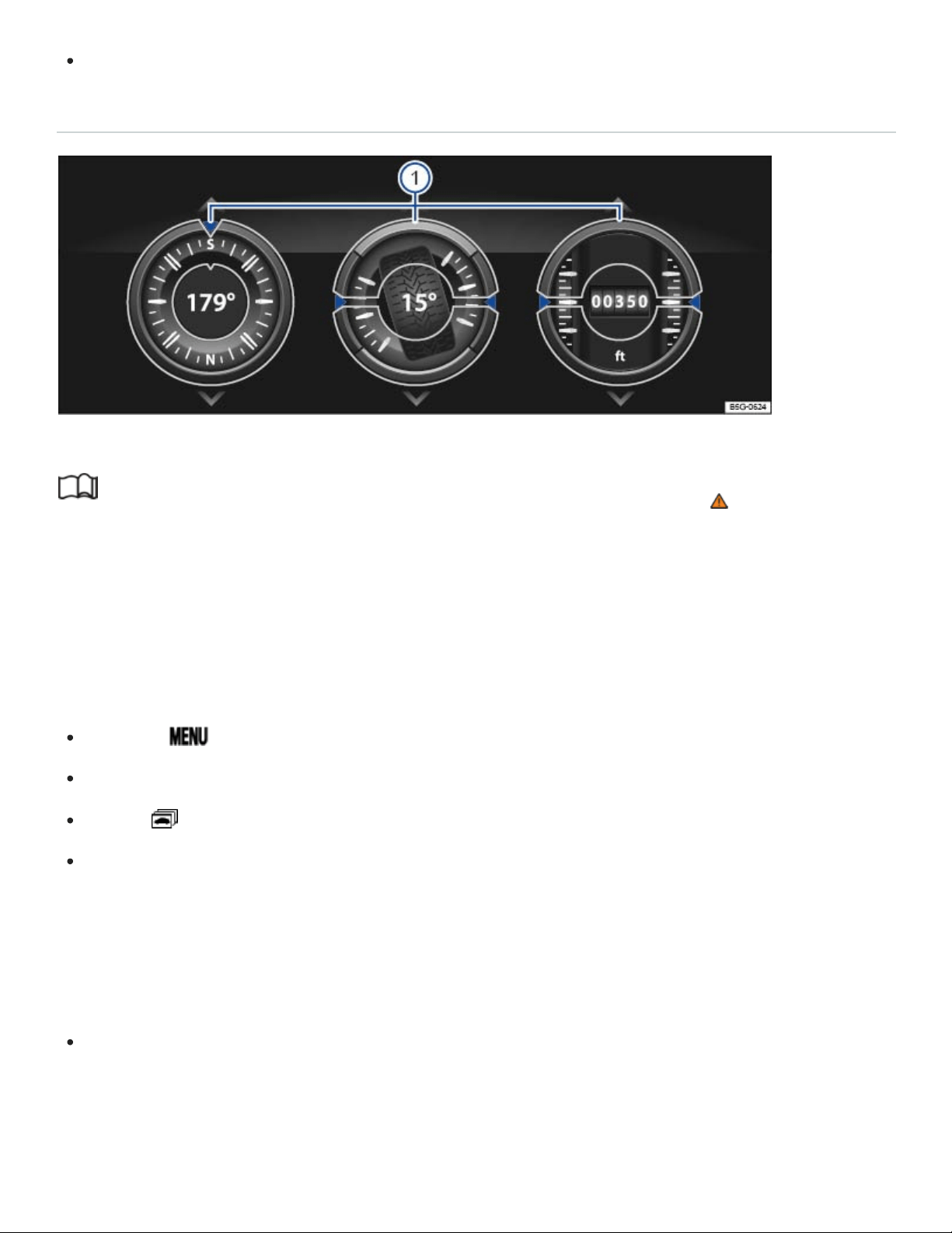
To switch to the driving position Sport (S), select a different driving mode.
Offroad display
Fig.118In the Infotainment system: Offroad display.
Read and follow the introductory information and safety information first⇒ Introduction to the
subject
Your vehicle may be equipped with an offroad display in the Infotainment system. These digital instru‐
ments show additional information about the vehicle and its surroundings and can help you to assess
the current driving situation more precisely.
Opening the off-road display
Press the button.
Tap the Vehicle function key.
Tap the function key.
Tap the Offroad function key.
Selecting instruments and setting units
The display in the Infotainment system can show a maximum of 3instruments at any given time
⇒Fig.118 ①.
Swipe your finger up or down on a gauge to select a different instrument.
For some gauges, the units can be changed in the Infotainment system ⇒Infotainment system opera‐
tion and displays .
Off-road display instruments

Compass: The compass shows the current driving direction.
Steering angle display: The steering angle of the vehicle is displayed. The value is positive for a
left steering angle and negative for a right steering angle.
Altimeter: The altimeter shows the current altitude above sea level (in the unit m or ft).
Engine coolant temperature gauge: The display corresponds to the engine coolant temperature
display in the instrument cluster.
Engine oil temperature gauge: The display corresponds to the engine oil temperature display in
the instrument cluster ⇒Engine oil .
Adapting the display areas to the driving situation
Select the 3 possible instruments that best correspond to the driving situation and the environmental
conditions or terrain, for example:
Sandy terrain: Engine oil temperature gauge, steering angle display, and engine coolant temper‐
ature gauge.
Inclines: Steering angle display, engine coolant temperature gauge, and altimeter.
Alpine terrain: Steering angle display, altimeter, and compass.
WARNING
Driving on today's roads demands the full attention of the driver at all times. Driver distraction
causes accidents, collisions and serious personal injury!
Never pay so much attention to the gauges in the Infotainment system that you fail to notice
what is going on around you.
NOTE
To help prevent engine damage, always avoid high engine speeds, full throttle acceleration and
heavy engine loads when the engine is cold.
Off-road driving
Introduction to the subject
In this chapter you will find information on the following subjects:

⇒Safety notes when driving off-road
⇒Technical terms explained
⇒Before driving off-road
⇒General rules and good driving practices
⇒Rollover warning
⇒Useful off-road driving equipment
⇒Selecting the right gear
⇒Driving in rough terrain
⇒Driving through water
⇒Driving in sand and mud
⇒If the vehicle is stuck
⇒Driving in steep terrain
⇒Driving crosswise on a slope
⇒Crossing ditches
⇒After driving off-road
Vehicles with All-wheel drive (4MOTION) can be driven on and off-road. In this chapter you will find
important information on driving your vehicle off-road. It is very important to review this chapter before
taking your vehicle off-road.
Driving off the beaten path is challenging - for the driver, the passengers, and the vehicle itself.

It requires special knowledge and skills different from those needed for highway driving. Successful
off-roading comes from a combination of theory and practice. This includes knowing the right way to
handle the expected and the unexpected ⇒ .
Safety must always have top priority. Never overestimate your own abilities or underestimate the diffi‐
culties that come with driving off-road. Never let determination get the better of your common sense.
If the going gets too difficult, turn back and find a better route to your destination.
The wide range of terrain you can come up against, and the many risks and dangers the terrain may
hide, make it impossible to foresee and deal in this Manual with every conceivable off-road situation
you may face. For this reason, it is vital for you to know what lies ahead and evaluate possible dan‐
gers before trying to drive over difficult or unfamiliar terrain.
The vehicle is not designed for trips with an expedition-like character.
In All-wheel drive (4MOTION) vehicles, different driving modes can be selected with 4MOTION Active
Control ⇒4MOTION Active Control .
Before driving off-road, switch off the driver assistance systems and parking assistance systems.
Checklist
Before using the vehicle off-road, follow these steps to be able to drive and control the vehi‐
cle off-road:
Read and pay attention to the safety notes for driving off-road Safety notes when driving off-road.
Sit so that you can clearly see the terrain in front of you.
Every occupant must properly fasten the safety belt belonging to the seat he or she occupies and
keep the belt properly fastened while riding in the vehicle Safety belts.
Wear shoes that give your feet a good grip and feel for the pedals.
WARNING
Not wearing safety belts, or wearing them improperly will increase the risk of serious injuries
when driving off-road. Holding the steering wheel improperly will reduce your ability to control the
vehicle and can also increase the risk of injury when driving off-road.
Properly worn safety belts are the single most effective means of reducing the risk of serious
injury and death during sudden braking or driving maneuvers and in automobile accidents. For

this reason, always wear your safety belt properly and make sure all passengers wear their
safety belts properly as well whenever the vehicle is moving.
Never wrap your thumbs around the steering wheel rim. When driving off-road, obstacles in
front of the wheels can make the steering wheel jerk suddenly in your hands and cause per‐
sonal injury. Rest your thumbs pointing up on the on the surface of the steering wheel at the
3and 9o'clock positions.
Tread lightly is an educational program designed to increase public awareness of land use regu‐
lations and responsibilities in our nation's wilderness areas. Volkswagen supports the U.S. Forest
Service and the Bureau of Land Management in encouraging you to preserve our national forests
and other public and private lands by treading lightly.
Leaking engine oil and brake fluid can pollute the environment. Collect leaking operating fluids
and dispose of them properly in accordance with applicable environmental laws and regulations.
Bring tools and other gear based on the special requirements of the trip you will be taking
Safety notes when driving off-road
Read and follow the introductory information and safety information first⇒ Introduction to the
subject
WARNING
The intelligent technology of the vehicle cannot change the laws of physics. Despite the ABS, ad‐
verse terrain can cause instability through blocked wheels – for example, if you brake hard when
driving on a loose gravel road. Difficult terrain may also prevent the ESC from doing its job.
WARNING
Inadequate experience and knowledge of the demands of off-road driving can lead to critical situ‐
ations and cause serious personal injury.
Never take routes or risks that could put you or your passengers in danger. If you cannot go
on, or have doubts about the safety of your route, turn back and take a new route.
Even terrain that looks easy can be difficult and dangerous, putting you and your passengers
in a critical situation. It is often best to check an area out on foot first.

Drive with special care and think ahead in off-road terrain. If you drive too fast, or fail to ma‐
neuver the vehicle properly, you could cause personal injury and damage the vehicle.
Never drive faster than is appropriate for the prevailing terrain and the road, traffic, and
weather conditions.
Never operate the vehicle at the limit of its performance ability. Always leave a good safety
margin.
Never drive too fast across embankments, ramps, or slopes. The vehicle could become air‐
borne. If that happens, you will not be able to steer and can lose control.
If your vehicle becomes airborne, always keep the front wheels pointing straight ahead. If the
wheels are not pointing straight ahead when the vehicle lands, it could roll over.
Even areas that look harmless can be dangerous. Potholes, ditches, trenches, drop-offs, dif‐
ferent kinds of obstacles, and soft or swampy ground often cannot be seen and can be par‐
tially or fully covered by water, grass, branches, or other things. Driving over such terrain can
cause accidents and severe injuries.
Never allow people to stand in front of or behind the vehicle if you have put items such as
stones or pieces of wood under the wheels to improve traction on slippery ground. Spinning
wheels can turn these items into dangerous flying objects causing serious personal injury.
WARNING
Utility vehicles have a significantly higher rollover rate than other types of vehicles.
In a rollover crash, an unbelted person is significantly more likely to die than a person wearing
a safety belt.
Your vehicle has a higher center of gravity and an increased risk of rollover while driving than a
standard passenger vehicle that is not suitable for occasional off-road use.
Never drive too fast, particularly through curves, and never attempt extreme driving
maneuvers.
Always adjust your speed and driving style to road, terrain, traffic, and weather conditions.
Transporting luggage or other objects on top of your vehicle raises the center of gravity and
can further increase the risk of rollover.
WARNING

Even areas that look harmless can be dangerous. Potholes, ditches, trenches, drop-offs, different
kinds of obstacles, and soft or swampy ground often cannot be seen and can be partially or fully
covered by water, grass, branches, or other things. Driving over such terrain can cause accidents
and severe injuries.
Before driving over unknown terrain, it is often best to check an area out on foot first.
Never take routes or risks that could put you or your passengers in danger. If you cannot go
on, or have doubts about the safety of your route, turn back and take a new route.
Never drive faster than is appropriate for the prevailing terrain and the road, traffic, and
weather conditions.
WARNING
Always avoid driving crosswise on a slope ⇒Driving crosswise on a slope .
If stopped crosswise on a slope, never get out of the vehicle using the doors that face down‐
hill. The combined center of gravity of the vehicle and its contents (passengers and load) can
shift, causing the vehicle to tip over and roll down the slope. Always exit the vehicle calmly us‐
ing the doors that face uphill.
WARNING
The cruise control system ⇒Cruise control , Front Assist system ⇒Forward Collision Warning
(Front Assist) , and the other driver assistance systems are designed for highway use. They are
completely unsuitable for off-road situations and can even be dangerous when used off-road.
To reduce the risk of loss of control and serious personal injury, never use the driver assist‐
ance systems when driving off-road.
WARNING
Never drive off-road if you are low on fuel. Too little fuel in the tank can cause an accident and se‐
rious injuries. You can also run out of fuel in a remote area where getting help is difficult or
impossible.
When the fuel tank is almost empty, fuel supply to the engine can be interrupted, especially
when driving over bumps, across slopes, and up and down hills. The interruption in fuel flow
could stall the engine during a maneuver in difficult terrain and make you lose control of the
vehicle.
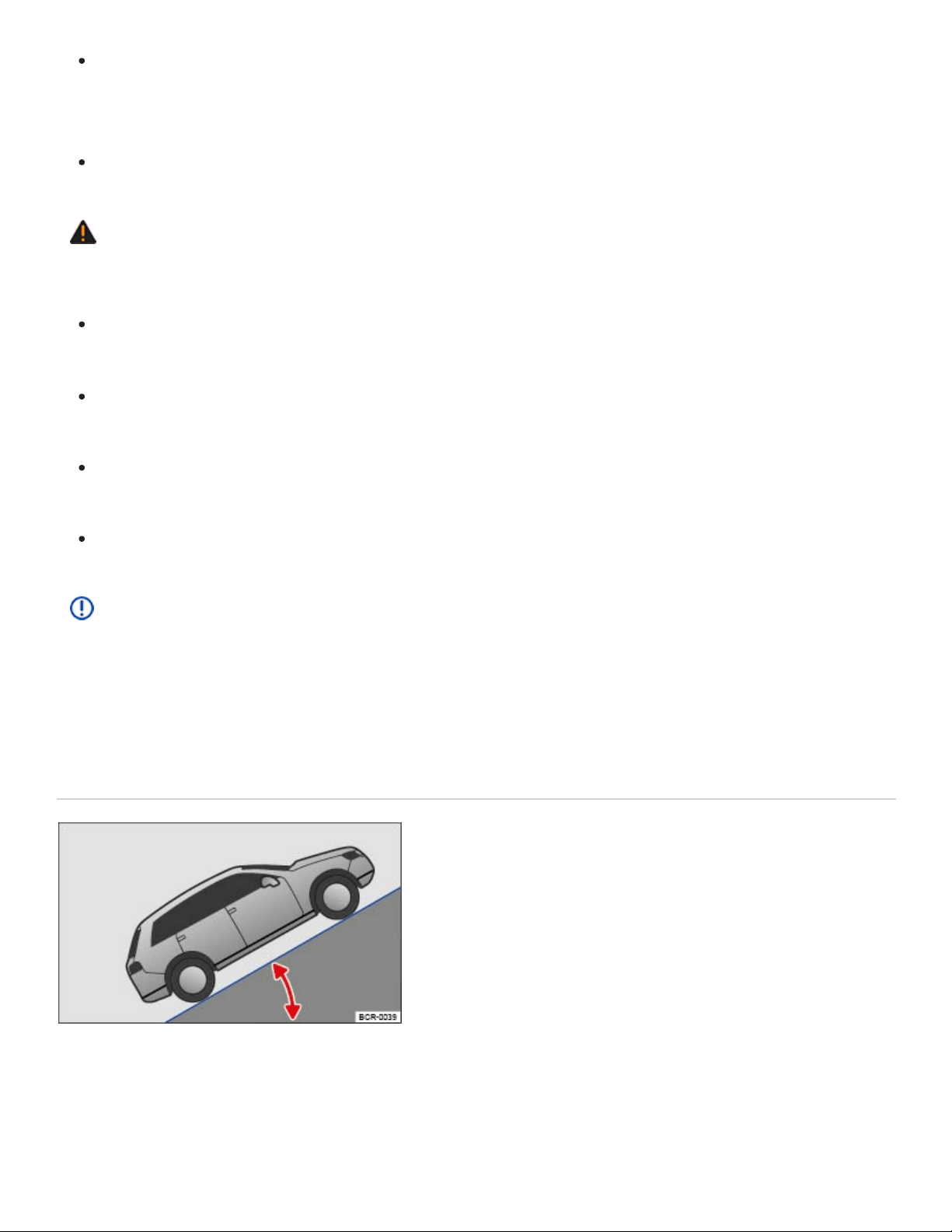
Steering and braking assistance as well as ESC and related systems will not work if the en‐
gine sputters or stalls due to lack of fuel. This can cause loss of vehicle control, especially in
difficult terrain.
Always refuel when the tank is 1/4 full to reduce the risk of running out of fuel.
WARNING
Driving through snow-covered terrain is very dangerous.
Never take routes or risks that could put you or your passengers in danger. If you cannot go on
or have doubts about the safety of your route, turn back and take a new route.
Potholes, ruts, ditches, drop-offs, and other obstacles are often partially or completely hidden
by the snow, especially when it is deep.
Snow-covered dangers can lead to an accident, serious personal injury, or stranding under ex‐
treme weather conditions.
Always adapt driving speed and style to load, terrain, visibility, and weather conditions.
NOTE
If the power sunroof or the windows are open when it rains or snows, the interior of the vehicle
will get wet and the vehicle may be damaged. Always keep the windows and the power sunroof
closed when driving off-road.
Technical terms explained
Fig.119Gradient angle.

Center of gravity
Ground clearance
Gradient angle
Lateral angle (vehicle slope)
Breakover angle
Approach/departure angles
Fall line
Articulation
Fig.120Lateral angle.
Read and follow the introductory information and safety information first⇒ Introduction to the
subject
The vehicle's center of gravity affects its rollover characteristics. Since the vehicle
has higher ground clearance for off-road driving, its center of gravity is also higher than that
of standard passenger cars. The higher center of gravity increases the risk of vehicle rollover
while driving. Always keep this in mind when driving. Heed the safety information and warn‐
ings in this Manual ⇒Safety notes when driving off-road .
The vertical distance between the level ground and the lowest part on the vehicle
⇒ .
The number of feet (meters) in altitude gained when traveling about 328ft (100m) is
given as a percentage or in degrees ⇒Fig.119 . The maximum slope the vehicle can climb
unassisted depends on road surface and engine power.
The maximum angle the vehicle may be driven across terrain without
the vehicle rolling over (depends on center of gravity) ⇒Fig.120 .
Maximum permitted angle given in degrees that a vehicle driven at low speed can
clear a ramp without the underbody of the vehicle scraping the ramp ⇒ .
The approach and departure angles are the transition from flat ground
to a slope, or from a slope to flat ground. The maximum angles (in degrees) the vehicle can
be driven at low speed along an embankment without the bumper or underbody scraping ⇒
.
The vertical drop route.
Articulation capability of the vehicle while driving on one side over an object.
WARNING
Never exceed the recommended maximum values listed for the vehicle ⇒Dimensions .
Exceeding these values will result in serious personal injury and/or damage to your vehicle.

All values listed are for ideal conditions and assume firm, even surfaces that are dry and not
slippery.
Off-road conditions will always be less than ideal. Always reduce the maximum values listed to
allow an adequate margin of safety between the ideal maximum value and your vehicle's ac‐
tual off-road situation.
Before driving off-road
Read and follow the introductory information and safety information first⇒ Introduction to the
subject
Checklist
For your own safety and that of your passengers, carry out each of the following steps in the
order listed before every off-road trip ⇒ :
Inform yourself thoroughly before exploring nature and the terrain you plan to visit.
Fill the fuel tank completely. Off-road driving consumes significantly more fuel than driving on
the road.
Check whether the tires are suitable for the off-road trip you are planning. For difficult terrain,
always use special off-road tires.
Check, and if necessary correct, the cold tire inflation pressure in all tires.
Fill engine oil up to the MAX mark so the engine can be properly lubricated. This is especially
important when driving through potholes and up and down hills.
Completely refill the windshield washer reservoir with water and window washer fluid.
Stow luggage as low and flat as possible in the vehicle. Safely secure all loose objects.
Do not plan extensive day trips. Consider the increased fuel consumption during off-road
driving.
Check the vehicle tool kit. Add tools and other gear based on the special requirements of the
trip you will be taking Vehicle tool kit.
WARNING
Disregarding the safety-related checklist may lead to accidents and serious personal injuries.

Always review and follow the checklist above. Follow commonly accepted safety practices and
use common sense.
All occupants must sit properly and wear safety belts whenever the vehicle is moving.
General rules and good driving practices
Read and follow the introductory information and safety information first⇒ Introduction to the
subject
Good driving practices
Special rules apply to off-road driving ⇒ :
Volkswagen recommends never driving off-road alone. At least 2 off-road vehicles should travel
together. Unexpected situations can occur. For this reason, take along the equipment you need to
call for help in case of an emergency.
Stop and explore the route on foot wherever necessary and always before traveling over difficult
trails or terrain.
Drive over hill crests slowly. Otherwise, the vehicle can tip and be damaged and disabled.
Drive slowly through difficult terrain segments. On slippery surfaces, upshift and keep the vehicle
moving.
Look for terrain that is firm and stable. Off-road ground is frequently soft, and the tires can sink
into it. This reduces ground clearance.
Even at low speeds, always follow other vehicles at a safe distance. If the first vehicle suddenly
gets stuck, the second vehicle can still stop in time without getting stuck as well.
WARNING
Off-road driving can be dangerous, can lead to accidents, vehicle damage, stranding in remote
areas, and serious personal injury.
Never drive too fast or for terrain and weather conditions.
Always adjust your speed and driving style to road, terrain, traffic, and weather conditions.
Always avoid sudden, sharp maneuvers that increase the risk of loss of vehicle control or get‐
ting stuck.
When driving off-road look and think ahead, expect the unexpected.

To reduce the risk of loss of control and serious personal injury, never use the cruise control
when driving off-road. Cruise control is designed for highway use. It is completely unsuitable
for off-road situations and can even be dangerous when used off-road.
NOTE
Always make sure the vehicle has enough ground clearance. Severe damage to the underbody
can occur if the vehicle bottoms out. The damage could disable the vehicle and leave you
stranded.
Rollover warning
Read and follow the introductory information and safety information first⇒ Introduction to the
subject
A vehicle's center of gravity affects its rollover characteristics. Since vehicle has higher ground
clearance for off-road driving, its center of gravity is also higher than that of standard passenger cars.
The higher center of gravity increases the risk of vehicle rollover while driving. Always keep this in
mind when driving. Heed the safety information and warnings in this Manual ⇒Safety notes when
driving off-road .
WARNING
Utility vehicles have a significantly higher rollover rate than other types of vehicles.
In a rollover crash, an unbelted person is significantly more likely to die than a person wearing
a safety belt.
Your vehicle has a higher center of gravity and an increased risk of rollover while driving than a
standard passenger vehicle that is not suitable for occasional off-road use.
Never drive too fast, particularly through curves, and never attempt extreme driving
maneuvers.
Always adjust your speed and driving style to road, terrain, traffic, and weather conditions.
Transporting luggage or other objects on top of your vehicle raises the center of gravity and
can further increase the risk of rollover.
Always avoid driving crosswise on a slope.

If stopped crosswise on a slope, never get out of the vehicle using the doors that face down‐
hill. The combined center of gravity of the vehicle and its contents (passengers and load) can
shift, causing the vehicle to tip over and roll down the slope. Always exit the vehicle calmly us‐
ing the doors that face uphill.
Useful off-road driving equipment
Read and follow the introductory information and safety information first⇒ Introduction to the
subject
The checklist lists only a few of the items that could be very helpful when driving off-road ⇒ . If you
have user's manuals or assembly instructions for the listed extra equipment, take them with you off-
road and heed them.
Checklist
Useful off-road driving equipment ⇒ :
Water, compass, maps, flashlight and spare batteries.
Cable winch, tow rod or tow rope strong enough for your vehicle.
Mobile phone, shovel, blankets, and rubber boots, tape measure, and yardstick.
Electric air compressor to connect to the 12volt outlet in the vehicle for inflating the tires.
A wooden plank about 2inches thick and 3feet long or similar aluminum frame as traction aid
for a stuck vehicle or as a base for the vehicle jack.
Snow chains for all 4tires, additional spare tires and vehicle tool kit.
WARNING
Accidents and severe personal injury can result from the improper use of tools or equipment as
well as from the use of tools or equipment that are damaged or not right for the job to be done.
Selecting the right gear
Read and follow the introductory information and safety information first⇒ Introduction to the
subject

Different kinds of terrain require different gears. Selecting the right one helps you to get through
safely.
Before driving over a difficult section, think carefully about which gear you should select. With time,
you will learn which gear is best for various types of terrain.
If you select the right gear you will usually not have to slow the vehicle down with the foot brake
when driving down slopes - the engine will help brake the vehicle. You will then only have to use
the brake when the braking power of the engine is not enough.
Never accelerate more than necessary when driving off-road. If you accelerate too hard, the
wheels could lose traction and you could lose control of the vehicle.
Use selector lever position (D) when driving on ordinary level areas.
On soft or slippery surfaces, drive at an appropriate speed and in the highest possible driving
range of the Tiptronic.
Use Tiptronic mode and shift into 1st gear when driving up or down steep hills ⇒Automatic trans‐
mission . Use Hill Start Assist (Hill Hold) ⇒Hill Start Assist (Hill Hold) .
Use Tiptronic mode and put the vehicle in 2nd or 3rd gear when driving through moderately diffi‐
cult off-road terrain, for example mud, sand, water, or hills ⇒Automatic transmission .
Driving in rough terrain
Read and follow the introductory information and safety information first⇒ Introduction to the
subject
Select the correct driving mode ⇒4MOTION Active Control and do not drive faster than a crawl over
rocky sections. Drive around obstacles such as rocks wherever possible. If this is not possible, care‐
fully advance until one front wheel is on the rock and then slowly drive over it ⇒ .
Even obstacles that are lower than your vehicle's ground clearance can come into contact with the
underbody and damage or disable your vehicle. Such obstacles are especially dangerous when the
ground around them is soft or there is a dip right in front of or behind them. They are also dangerous
if you drive over them too quickly and the shock absorbers are compressed.
NOTE
If you are facing a large rock or tree stump or other large obstacle, do not attempt to drive
straight over it or to climb over it with just 2 wheels. A rock or other obstacle that is too high for

your vehicle to clear will damage and may disable the vehicle if you try to drive over it. You
could be stranded far away from help. Never let large obstacles pass under the vehicle. If
there is no way around them and they are too large to drive over, back up and find another
route.
Even obstacles that are lower than your vehicle's ground clearance can come into contact with
the underbody and damage or disable your vehicle. Such obstacles are especially dangerous
when the ground around them is soft or there is a dip right in front of or behind them. They are
also dangerous if you drive over them too quickly and the shock absorbers are compressed.
Driving through water
Read and follow the introductory information and safety information first⇒ Introduction to the
subject
Important factors when deciding whether to drive through water:
Water depth.
Strength of the current.
Firmness of stream bed and bank.
Shape of the bank.
Objects in the water.
Maximum ground clearance of the vehicle ⇒Dimensions .
Driving through standing and slow-moving water
Driving through water can damage the vehicle.
The water must not be any higher than the bottom of the vehicle body. Always drive carefully
through water depths lower than the vehicle body ⇒ .
Never exceed maximum ground clearance ⇒Dimensions .
Only drive through water where the ground under the water is firm enough ⇒ .
Also pay attention to information about driving through water on roads ⇒Driving through water on
roads .
Driving through fast-moving water

Driving through fast-moving water is very dangerous ⇒ .
The vehicle can be swept away by the current. Even vehicles with high ground clearance can get
stuck if the ground is washed out from under the tires. Fast-moving water will build up against the
side of your vehicle. This will make the water deeper. Always think about this before entering the wa‐
ter. Water volume, speed, and depth can be very unpredictable and dangerous.
If you are uncertain how fast the water is flowing, look for a shallower place where you can cross in
safety. If you cannot find a safe place to cross, turn back.
WARNING
Flowing water is very powerful and can sweep your vehicle away. This can lead create an ex‐
tremely dangerous situation and cause an accident with serious personal injuries.
Never take routes or risks that could put you or your passengers in danger. If you cannot go on
or have doubts about the safety of your route, turn back and take a new route.
Never stop in the water.
If water gets into the engine, your vehicle can break down. You will lose control of a broken
down vehicle, and it can be swept away.
Soft surfaces, mud, underwater obstacles, and holes can cause accidents and can cause the
vehicle to break down in the water. This can lead pose extreme danger.
Rapidly flowing water can develop strong forces that can pull the vehicle downstream. This
can cause accidents and fatal injuries.
Drive through water only where the banks and bottom are firm enough and the water is shal‐
lower at all points than the maximum ground clearance for your vehicle ⇒Dimensions .
NOTE
Vehicle components such as the engine, drive train, suspension or electrical system may be
severely damaged by driving through water.
Avoid stopping in deep water. This can let water get inside the vehicle.
On soft ground, the tires dig into the surface. This can cause the water to rise above the vehi‐
cle body. Make sure that the ground is sufficiently firm.
Avoid creating a bow wave in front of the vehicle while driving through water. A bow wave
could force its way into the engine air intake duct and seriously damage the engine.

If water rises above the vehicle body, severe engine damage will result. This engine damage
will lead to a vehicle breakdown. This can disable the vehicle in the water.
Never drive over salt flats or through salt or salty water. Salt causes vehicle corrosion. Rinse
all parts of the vehicle that were exposed to salt or salt water right away with fresh water.
Driving in sand and mud
Read and follow the introductory information and safety information first⇒ Introduction to the
subject
Check whether ESC and ASR are active. ⇒Braking assistance systems .
Select an appropriate driving mode ⇒4MOTION Active Control .
Select a suitable gear and stay in this gear until solid ground is reached ⇒Selecting the right
gear .
Always drive at a constant speed through sand and mud; do not shift gears manually and do not
stop.
Never drive too fast through sand and mud. The wheels may spin and the vehicle can get stuck.
Do not change your speed or your direction.
If the vehicle skids, steer in the direction the vehicle is sliding to try to get it back under control.
If the tires no longer grip, turn the steering wheel back and forth slightly in short, quick
movements.
WARNING
Driving through sand and mud can be dangerous. The vehicle can skid out of control and crash,
causing serious injuries. Always drive carefully when driving in sand and mud.
Never take routes or risks that could put you or your passengers in danger. If you cannot go on
or have doubts about the safety of your route, turn back and take a different route.
WARNING
Driving on tires that are not inflated to the correct cold tire inflation pressure can cause an acci‐
dent with serious or fatal injuries.

If the tires are not inflated to the correct pressure, they will wear out faster and the vehicle will
not handle as well.
Incorrect tire pressure can make tires overheat, resulting in tire damage including tire tread
separation and sudden blowouts that can make you lose control of the vehicle.
If the vehicle is stuck
Read and follow the introductory information and safety information first⇒ Introduction to the
subject
A vehicle is stuck if the wheels stick so far into the ground, that the vehicle cannot drive forward or
backwards through its own power.
It takes experience and a fine touch to rock a vehicle back and forth to get it going when it is stuck. If
you go about it the wrong way, you'll dig the vehicle in even deeper and need someone to tow you
free.
Preparations
Carefully dig out all 4 wheels and make sure that no other parts of the vehicle are stuck in the
sand or mud.
Select reverse gear.
Carefully accelerate and try to back up in your own track.
If this doesn't help, try placing brushwood, floor mats, or burlap sackcloth directly in front of the tires
to improve grip and traction ⇒ .
Rocking the vehicle free
Don't spin the wheels. It's unlikely to help you get going and all but certain to dig you in even deeper if
you do it too much ⇒ .
Switch off Anti-Slip Regulation (ASR) ⇒Braking assistance systems .
Turn the steering wheel so that it points straight ahead.
Shift into reverse and accelerate just to the point where the wheels first start to spin.
Immediately engage first gear and accelerate again until the wheels just begin to spin.

Repeat this process to get the vehicle to rock back and forth and then hopefully develop enough
forward momentum to get going again.
Once the vehicle is free, switch ASR back on.
WARNING
Make sure there are no people or animals in front of or behind the vehicle, especially when it is
stuck and you are trying to rock it loose.
Stones, brush, pieces of wood, and other objects under the wheels can be thrown at great ve‐
locity when the wheels spin. This can cause serious or even fatal injuries.
If the stuck vehicle suddenly regains traction, it will lurch forward and can run over anybody
who is standing too close to it in the front or in the back.
Driving in steep terrain
Read and follow the introductory information and safety information first⇒ Introduction to the
subject
Driving on slopes
Before driving up or down a slope, get out of the vehicle, explore the terrain, and assess the
situation.
Walk the grade you intend to drive, check the stretch for firmness and obstacles or other hidden
dangers ⇒ .
Find out how the route continues at the end of a steep angle.
If the route is too steep or too uneven or the ground is too loose, do not drive this route. Find an
alternative.
Drive at a slow, constant speed straight up or down a slope.
Never stop or try to turn around on a slope.
Use just as much power as needed to get up the slope. Too much power makes the tires slip,
spin, or lose traction. This can increase your risk of losing control. However, too little power will in‐
crease the likelihood of stalling.
Do not change gears while climbing the slope.
Use the off-road display ⇒Offroad display .

If you get stuck while driving up a slope
Never try to turn around.
If your engine stalls, apply the foot break and restart the engine.
Shift into reverse and back your vehicle carefully straight down the slope.
Use the brake to keep the speed steady when backing down to a safe place.
Driving down a slope
There is an increased risk of rollover when driving down a slope. For this reason, concentrate on
steering safely down the slope.
Drive down steep slopes in first gear.
Gently apply the foot brake to help keep the vehicle under control.
Never exceed the vehicle's maximum lateral angle (vehicle slope).
If it is possible and if it is not dangerous, drive straight down the fall line (maximum slope).
Use the off-road display ⇒Offroad display and Hill Descent Control ⇒Hill Descent Control on
steep descents.
WARNING
Never try to drive up or down slopes that are too steep for your vehicle. The vehicle could slide
away, tip over, or roll over.
Never take routes or risks that could put you or your passengers in danger. If you cannot go on
or have doubts about the safety of your route, turn back and take a new route.
The lateral angle must never be more than the maximum angle approved for the vehicle.
Always drive along the fall line when driving up or down a slope.
Never try to turn the vehicle around on a slope. The vehicle could tip over or roll down the
slope.
If the engine stalls or you can no longer drive up the slope for any reason, stop and apply the
foot brake. If stalled, apply the foot brake and restart the engine. Then shift into Reverse (R)
and carefully back your vehicle straight down the slope along the fall line. Keep the vehicle
speed slow and even.
If the engine will not restart, apply constant pressure to the foot brake and carefully back
straight down the slope the same way you drove up. Keep the vehicle speed slow and even.
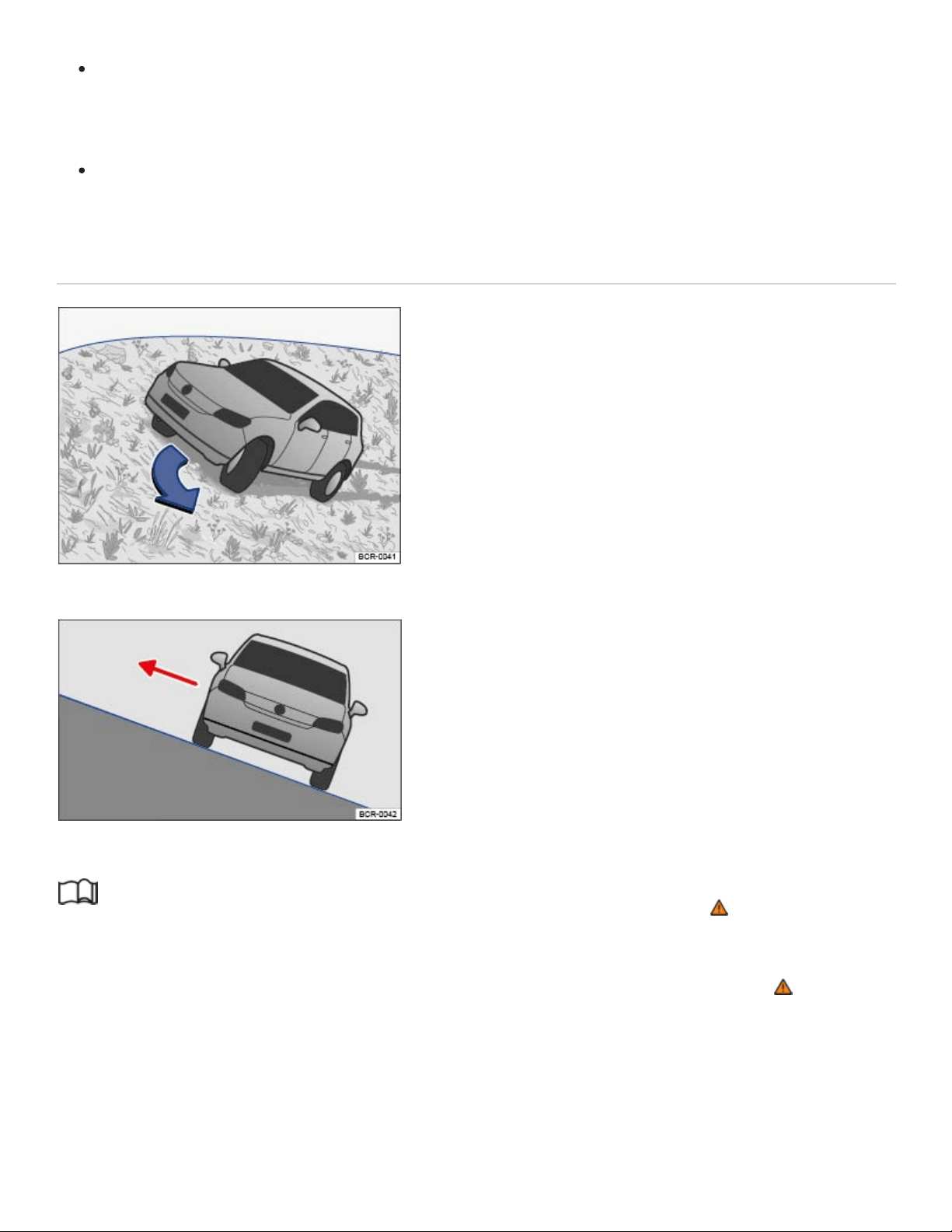
If the engine is running, select Reverse and carefully back straight down the slope the same
way you drove up. Use engine braking power and the foot brake to keep the vehicle speed
slow and even.
Never just roll down a slope with the transmission in Neutral (N). You could lose control of the
vehicle.
Driving crosswise on a slope
Fig.121Steer downhill along the fall line.
Fig.122On a slope, always exit on the uphill side of the vehicle.
Read and follow the introductory information and safety information first⇒ Introduction to the
subject
Driving crosswise on a slope is one of the most dangerous off-road driving situations ⇒ .
Before driving crosswise on a slope, check whether there is a different, safer route.
Even if it seems harmless, never underestimate the difficulties and hazards when driving crosswise
on a slope. A vehicle perpendicular to the slope of the hill can become uncontrollable and slide away,
tip, or roll over. This could cause severe or fatal injuries to all occupants.

The vehicle center of gravity should be as low as possible. Taller or heavier passengers should sit
on the higher side of the vehicle. Luggage on the roof should be removed and heavy objects
should be secured, as the vehicle could tilt due to the sudden shifting of objects in the vehicle ⇒
.
Make sure the ground is firm and even along your route. If the ground is soft or slippery, the vehi‐
cle is more likely to slip away to the side. Make sure that the angle does not become too great due
to surface unevenness. This can make the vehicle tip and roll over.
The steeper the slope across which the vehicle is moving, the more important it becomes to make
sure the wheels on the lower side do not run over holes or depressions. The wheels on the high
side must never run over protruding rocks, tree stumps, or other obstacles.
If the vehicle threatens to tip, immediately steer downhill into the fall line and gently accelerate
⇒Fig.121 . If it is not possible to steer down the fall line, steer uphill and gently accelerate.
WARNING
Never try to drive crosswise on a slope, especially one that is too steep for your vehicle. The ve‐
hicle could slide sideways and tumble down the slope. To reduce the risk of accidents and seri‐
ous injuries:
Never underestimate the difficulties and dangers of driving crosswise on a slope. Never take
routes or risks that could put you or your passengers in danger. If you cannot go on or have
doubts about the safety of your route, turn back and take a different route.
When driving crosswise on a hill, the vehicle can lose its hold, slide sideways, tip or turn over
and roll down the hill.
Make certain that the wheels on the downhill side of the vehicle do not run over holes or de‐
pressions. Make certain that the wheels on the high side of the vehicle do not run over rocks,
tree stumps, or protruding objects.
Before driving crosswise on a hill, check whether it is possible to steer into the fall line along
the selected route. If this is not possible, select a different route. If the vehicle threatens to tip,
immediately steer downhill into the fall line and gently accelerate ⇒Fig.121 .
If the vehicle is stopped on a hillside and is laterally tilted, avoid sudden and uncontrolled
movement in the vehicle The vehicle can lose its hold, slide sideways, tip, or turn over and roll
down the hill.
If the vehicle is stopped while pointed crosswise on a steep slope, make certain that no one
exits the vehicle through a door on the downhill side. This can shift the vehicle center of gravity

to the downhill side. The can tilt or roll over and roll down the hill. To help minimize this risk,
always exit the vehicle through the doors that are facing uphill ⇒Fig.122 .
When getting out, make certain that doors opened on the uphill side are not closed carelessly
and do not swing shut due to their own weight and injure anybody.
Crossing ditches
Read and follow the introductory information and safety information first⇒ Introduction to the
subject
Check whether the approach/departure angle and the lateral angle (tilt) are small enough to allow
the vehicle to cross the ditch ⇒ .
Find a suitable area for crossing the ditch.
If possible, cross the ditch at an acute angle ⇒ .
This is only possible if the lateral angle (side-to-side tilt) is not too large.
WARNING
If the approach/departure angle or the lateral angle of the ditch is too steep for the vehicle, do not
attempt to cross the ditch. The vehicle can fall over on its side, slide sideways, or turn over.
NOTE
If ruts and depressions become too deep, the vehicle underbody can bottom out and get stuck.
This can damage or even disable the vehicle.
NOTE
If you enter at right angles to the ditch, the front wheels will fall into the ditch. The underbody of
the vehicle can get stuck and the vehicle can be damaged or disabled. Getting out of a ditch with‐
out assistance is rarely possible, even with all-wheel drive.
After driving off-road
Read and follow the introductory information and safety information first⇒ Introduction to the
subject

After an off-road drive, you always need to check the vehicle's underbody for damage and may need
to clean the radiator grille ⇒ .
Checklist
Checklist: Perform after every off-road drive ⇒ :
Clean the vehicle.
Check tires, suspension struts, and axles for damage and remove coarse dirt, stones, and for‐
eign objects from the tire tread.
Examine the vehicle underbody and remove objects such as twigs, leaves, or bits of wood that
have gotten stuck in the brake system, the wheels, the suspension, the exhaust system, of the en‐
gine . If damage or leaks are detected, see an authorized Volkswagen dealer or an authorized
Volkswagen Service Facility.
Check the engine compartment to for dirt that interferes with engine operation In the engine
compartment.
WARNING
Objects trapped under the vehicle floor can damage the brake system, fuel lines, gaskets, and
other underbody parts. Such objects can also ignite on contact with hot vehicle components. You
must check after each off-road outing to see whether any foreign objects have gotten stuck in the
vehicle underbody.
Never drive the vehicle if any foreign objects are stuck in the brake system, the wheels, the
suspension, the exhaust system, or the engine or engine compartment.
Flammable materials such as dry leaves or twigs can catch fire from contact with hot vehicle
components. A fire can cause serious personal injuries.
Trapped objects can damage or block the fuel lines, the brake system, gaskets, and other
parts of the suspension system. This can cause you to lose control of the vehicle and have an
accident.
NOTE
Dust, sand, grit, and other material that has collected in the air filter after driving in certain kinds
of off-road terrain can be drawn into the engine and cause expensive damage. After driving off-
road where it is very dusty or sandy, be sure to have the air filter checked and, if necessary,
cleaned by an authorized Volkswagen dealer or authorized Volkswagen Service Facility.

Driver assistance systems
Cruise control
Introduction to the subject
In this chapter you will find information on the following subjects:
⇒Using cruise control
⇒Tips and troubleshooting
Your vehicle may be equipped with cruise control, which helps maintain an individually stored con‐
stant speed.
Cruise control slows down the vehicle only by reducing the flow of fuel to the engine, not by braking ⇒
.
Speed range
Cruise control is available when driving forward at speeds above about 15mph (20km/h).
Driving with cruise control
You can exceed the stored speed at any time, for example, when passing another vehicle. Speed reg‐
ulation is interrupted while you accelerate and then resumed to the stored speed.
Operating cruise control
You can operate cruise control with the multi-function steering wheel ⇒Using cruise control .
Displays
Different cruise control versions are available. The stored speed is shown in the instrument
cluster display, depending on equipment.
Cruise control is regulating speed.
Cruise control is regulating speed.
Displayed in gray or small: Cruise control not regulating speed. Shown in white or large:
Cruise control regulating speed.

If no speed is stored, is shown in the instrument cluster display instead of the speed.
Driving downhill with cruise control
If cruise control cannot maintain constant speed while driving downhill, slow the vehicle with the foot
brake and downshift if necessary.
WARNING
Using the cruise control when it is not possible to drive safely at a constant speed can be danger‐
ous and can lead to an accident and serious personal injuries.
Never use cruise control when driving in heavy or varying traffic or when you cannot keep a
safe distance between you and the vehicles ahead of you.
Never use cruise control on steep, winding, or slippery roads (such gravel roads, wet roads, or
snowy or icy roads) or on roads with standing water.
Never use cruise control when driving off-road or on unpaved roads.
Always adjust your speed and the distance you keep between you and the vehicles ahead of
you to the road, traffic, weather, and visibility conditions.
To help prevent unintended operation of cruise control, switch the system off when it is not be‐
ing used.
It is dangerous to use the Resume feature when the previously set speed is too high for the
existing road, traffic, or weather conditions.
When going downhill, the cruise control may not be able to maintain a constant speed. The ve‐
hicle will speed up because of its own weight. Downshift and/or use the foot brake to slow the
vehicle.
Using cruise control

Fig.123Left-hand side of the multi-function steering wheel: Buttons for operating the cruise control.
Read and follow the introductory information and safety information first⇒ Introduction to the
subject
Switching on
Press the button.
System is switched on, but does not regulate vehicle speed until a speed is set.
Setting the current speed
Press the button when the vehicle is moving.
The current vehicle speed is set; cruise control helps to maintain this speed.
The green indicator light or comes on.
Adjusting the set speed
You can adjust the stored speed while cruise control is regulating by briefly pressing the fol‐
lowing buttons:
+1mph (1km/h)
-1mph (1km/h)
To adjust the stored speed continuously, press and holdthe or button.
Cruise control will accelerate to adapt the vehicle speed, or slow the vehicle down without braking by
reducing the flow of fuel to the engine until the new lower speed is reached.
Temporarily deactivating cruise control
Briefly press the or button on the multi-function steering wheel.

OR: Depress the brake pedal.
The speed stays stored in the memory.
Resuming cruise control
Press the button.
Cruise control resumes at the speed previously set.
Switching off
Press and hold the button.
The cruise control system is switched off and the stored speed is deleted.
Tips and troubleshooting
Read and follow the introductory information and safety information first⇒ Introduction to the
subject
Cruise control system malfunction
Have the system checked by an authorized Volkswagen dealership or authorized Volkswagen
Service Facility.
Cruise control is automatically deactivated or temporarily interrupted
If the system detects an error that could affect the function of the cruise control.
If the vehicle has accelerated and goes faster than the stored speed for a longer time.
If the brake pedal is depressed.
If regulation related to driving dynamics is taking place, for example, through ESC.
If an airbag deploys.
If the selector lever is shifted to Neutral (N). The cruise control will not deactivate when shifting
between D/S and Tiptronic mode.
If there is an automatic braking maneuver from the Forward Collision Warning (Front Assist) sys‐
tem ⇒Forward Collision Warning (Front Assist) .
If the system does not respond as expected, switch the system off and have it checked by an autho‐
rized Volkswagen dealership or authorized Volkswagen Service Facility.

Adaptive Cruise Control (ACC)
Applicable only in the United States
Introduction to the subject
In this chapter you will find information on the following subjects:
⇒Special driving situations
⇒Limits of ACC
⇒Switching ACC on and off
⇒Adjusting settings for ACC
⇒Tips and troubleshooting
Your vehicle may be equipped with the Adaptive Cruise Control system (ACC), which helps maintain
an individually stored constant speed and a previously set speed-dependent distance interval be‐
tween your vehicle and those in front of you.
In certain situations, your vehicle may be braked to a standstill by an automatic braking
maneuver⇒ .
ACC speed range
ACC works when the vehicle speed is between about 20mph (30km/h) and 95mph (150km/h).
Driving with ACC
You can override control by ACC at any time. Control will be interrupted if you brake. If you acceler‐
ate, control will be interrupted while you are accelerating and then resumed.
When towing a trailer, ACC may work only with limited functionality ⇒Trailer towing .
Driver intervention warning
Adaptive Cruise Control has system-related limits. As a driver, you must control the speed and the
distance to other vehicles under some circumstances. If the deceleration of the ACC automatic brak‐
ing system is not sufficient to bring the vehicle to a full stop in time, a message in the instrument clus‐
ter display and a red warning light come on. Depress the brake pedal!

Radar sensor
The ACC system works together with the Forward Collision Warning (Front Assist) system, if
equipped ⇒Forward Collision Warning (Front Assist) . Both systems use the same radar sensor at
the front of the vehicle to monitor the traffic situation ⇒Front view .
WARNING
Always remember that the Adaptive Cruise Control has limits– Using Adaptive Cruise Control
when it is not possible to drive safely at a constant speed can be dangerous and can lead to an
accident and serious personal injury.
Adaptive Cruise Control will not slow the vehicle down or maintain the set distance when you
drive towards an obstacle or something on or near the road that is not moving, such as vehi‐
cles stopped in a traffic jam, a stalled or disabled vehicle.
Always adjust your speed and the distance you keep between you and the vehicles ahead of
you to the road, traffic, weather, and visibility conditions.
Never use Adaptive Cruise Control on steep, winding, or slippery roads (such gravel roads,
wet roads, or snowy or icy roads) or on roads with standing water.
Never use Adaptive Cruise Control when driving off-road or on unpaved roads.
Always remember that the Adaptive Cruise Control cannot detect a vehicle that is driving to‐
wards you in your traffic lane and that it cannot detect narrow vehicles such as motorcycles
and bicycles.
Never follow a vehicle so closely that you cannot stop your vehicle safely. The Adaptive Cruise
Control cannot slow or brake the vehicle safely when you follow another vehicle too closely.
Always remember that the Adaptive Cruise Control has a braking power that is only about 30%
of the vehicle's maximum braking ability, under certain circumstances the automatic braking
function cannot bring the vehicle to a stop in time.
Always turn off Adaptive Cruise Control when entering turn lanes, exit lanes and construction
zones or in similar situations because the vehicle will automatically accelerate to the stored
speed when the road ahead is clear.
To help prevent unintended operation of Adaptive Cruise Control, switch the system off when it
is not being used.
It is dangerous to use the Resume feature when the previously set speed is too high for the
existing road, traffic, or weather conditions.

When traveling downhill, the Adaptive Cruise Control may not be able to maintain a constant
speed. The vehicle will speed up because of its own weight. Downshift and/or use the foot
brake to slow the vehicle.
Never allow the closing speed between you and other vehicles to be so high that the Adaptive
Cruise Control may not be able to slow your vehicle safely. If closing speed is too high, you
must apply the brakes yourself to reduce the risk of a rear-end crash.
If a driver intervention warning or Front Assist warning appears in the instrument cluster dis‐
play, immediately take over the control of the brake and gas pedals and slow down the vehicle
or bring it to stop when necessary and according to the traffic situation.
Always be prepared to take over the control of the brake and the gas pedal in every situation.
NOTE
If you suspect that ACC doesn't work properly or the sensors are damaged, switch off ACC
immediately.
See an authorized Volkswagen dealer or Volkswagen Service Facility for assistance and have
the ACC system checked.
The maximum speed for ACC is restricted to 95mph (150km/h).
If the ACC is active, you may hear noise during the automatic braking procedure. This is normal;
the noises are caused by the braking system.
Certain settings are automatically saved by the driver personalization feature ⇒Driver
Personalization .
A Declaration of Compliance with the United States FCC and Industry Canada regulations is on
⇒Declaration of Compliance, Telecommunications and Electronic Systems .
Special driving situations
Read and follow the introductory information and safety information first⇒ Introduction to the
subject
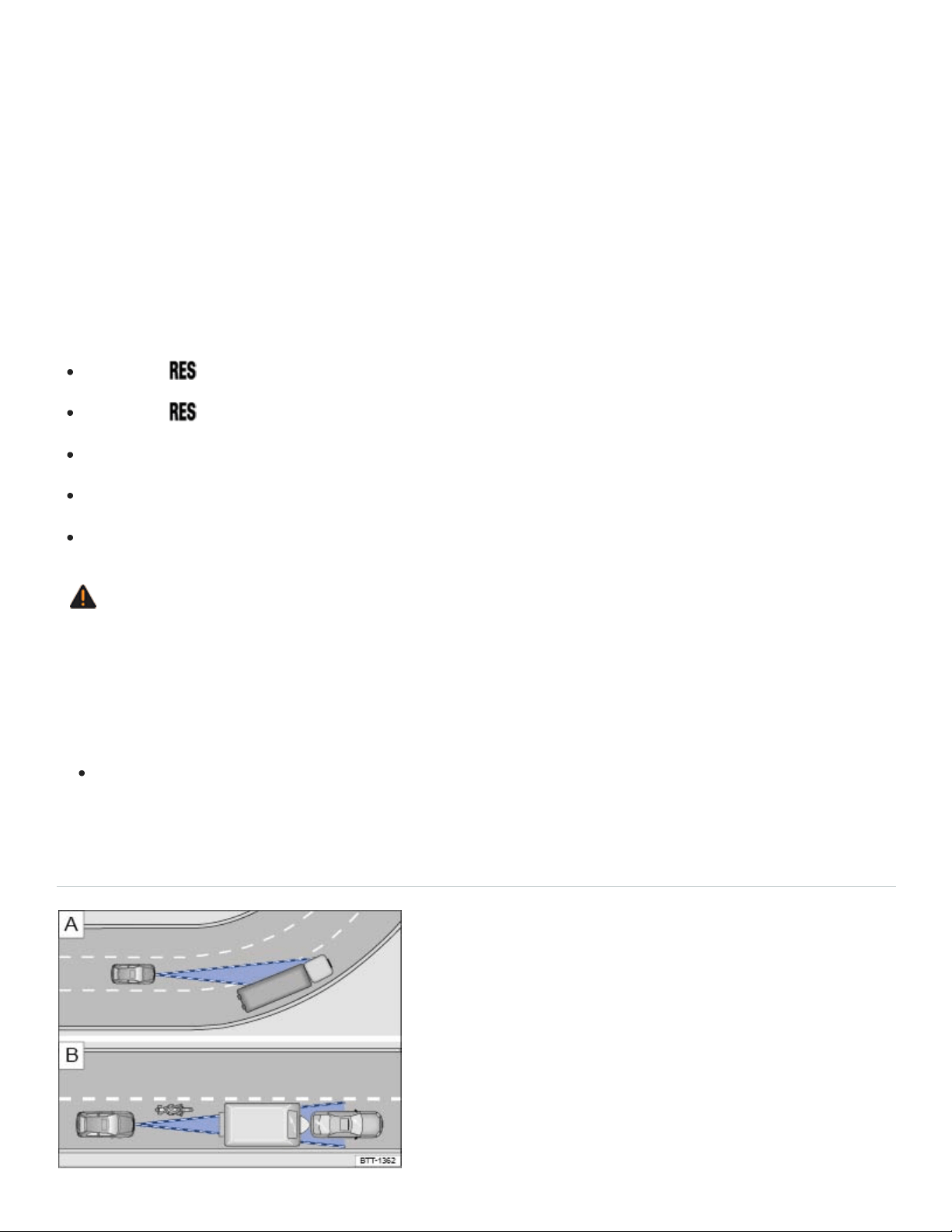
Adaptive Cruise Control has physical and system-related limits. The driver may therefore find that, in
certain circumstances, some Adaptive Cruise Control reactions are unwanted or occur with a delay.
You should therefore always be prepared to take full control of the vehicle whenever necessary.
Stop and go traffic
The ACC will brake your vehicle to a standstill if a moving vehicle directly ahead of your vehicle
brakes to a standstill. The vehicle is then held stationary by the brakes. As long as the text message
ACC is ready appears in the instrument cluster (which lasts no longer than a few seconds), ACC will
resume speed regulation as soon as the vehicle in front starts moving again.
Press the button on the multi-function steering wheel.
Press the button or briefly depress the gas pedal.
The vehicle standstill lasts longer than about 3 minutes.
A vehicle door is opened.
The ignition is switched off.
WARNING
As long as ACC is ready appears in the instrument cluster, your vehicle will start moving again
automatically as soon as the vehicle ahead starts moving again. In some cases the radar sensor
may be unable to detect obstacles in the vehicle's path. This can result in serious injury and
accidents.
Always check the road ahead before the vehicle pulls away. If necessary, cancel the pulling
away procedure by depressing the brake pedal.
Limits of ACC
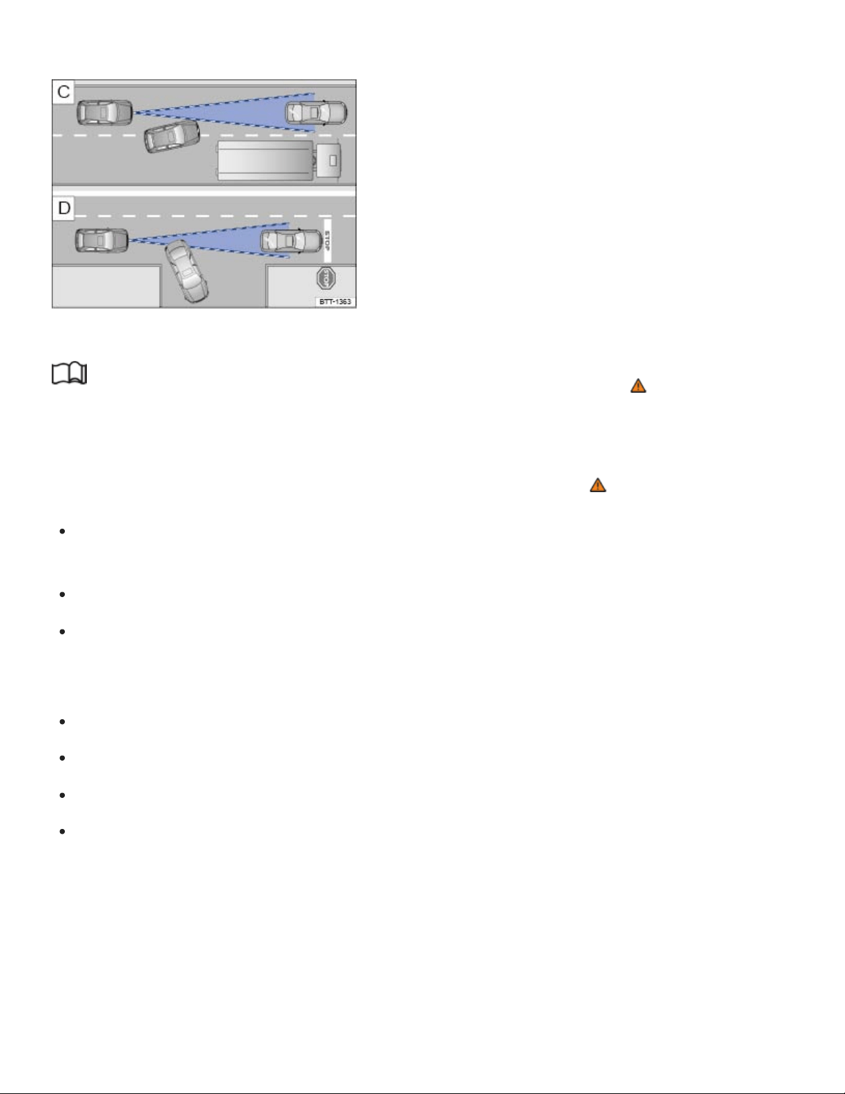
Fig.124 Driving in a curve. Motorcycle traveling ahead outside of the sensor range.
Fig.125 Vehicle changing lanes. A turning and a stopped vehicle ahead.
Read and follow the introductory information and safety information first⇒ Introduction to the
subject
When to switch off ACC
Switch off ACC under the following conditions due to system limitations ⇒ :
When driving around curves, turn lanes, highway ramps, or construction zones; to prevent un‐
wanted acceleration of the vehicle.
When driving through tunnels.
On roads with more than one lane, if other vehicles are driving more slowly in the fast lane.
Vehicles in other lanes will normally not be detected and will, in this case, be passed from the
slow lane.
When driving in multi-level garages or parking structures.
When there are metal objects, for example, tracks or metal plates in the road.
When driving on roads with gravel or loose pavement.
Under bad weather conditions or bad visibility, for example, in heavy rain, snowfall, or fog.
Things that can prevent the radar sensor from working properly
If the radar sensor function is impaired by heavy rain, spray, snow or mud, Adaptive Cruise Control
switches off temporarily. A driver information message appears in the instrument cluster display.
Clean the radar sensors as required.

The Adaptive Cruise Control will automatically be available again as soon as the radar sensor is
working properly. The message in the instrument cluster display switches off, and the Adaptive Cruise
Control can be reactivated.
Strong reflected radar signals, for example, in multilevel parking structures, can prevent the radar
sensor from working properly.
Objects that cannot be detected
The ACC radar sensor can only detect vehicles that are moving in the same direction as your vehicle.
Objects that cannot be detected by the radar sensor include:
People.
Animals.
Stopped vehicles, such as a broken-down vehicle or a vehicle that is stopped at the end of a traf‐
fic jam.
Vehicles crossing in front of your vehicle.
Oncoming traffic in your lane.
Other stopped objects.
If a vehicle detected by Adaptive Cruise Control turns or changes lanes and there is a stopped vehicle
in front of that vehicle, the system will not react to the stopped vehicle ⇒Fig.125 . If required,
brake the vehicle yourself.
Driving around curves and traffic circles
When driving into a curve and driving out of a long curve, the radar sensor may react to a vehicle in
the next lane ⇒Fig.124 . In such situations, the vehicle might decelerate unnecessarily or not re‐
act to the vehicle in front. In this case, you must either override the ACC by depressing the accelera‐
tor, interrupt the braking procedure by depressing the brake pedal, or press the button on the
multi-function steering wheel ⇒Switching ACC on and off .
Narrow vehicles and vehicles offset to one side
Narrow vehicles and vehicles traveling slightly to the left or right of your vehicle can only be detected
by the radar sensor when they are within sensor range ⇒Fig.124 . This applies especially to nar‐
row vehicles such as motorcycles. If required, brake the vehicle yourself.
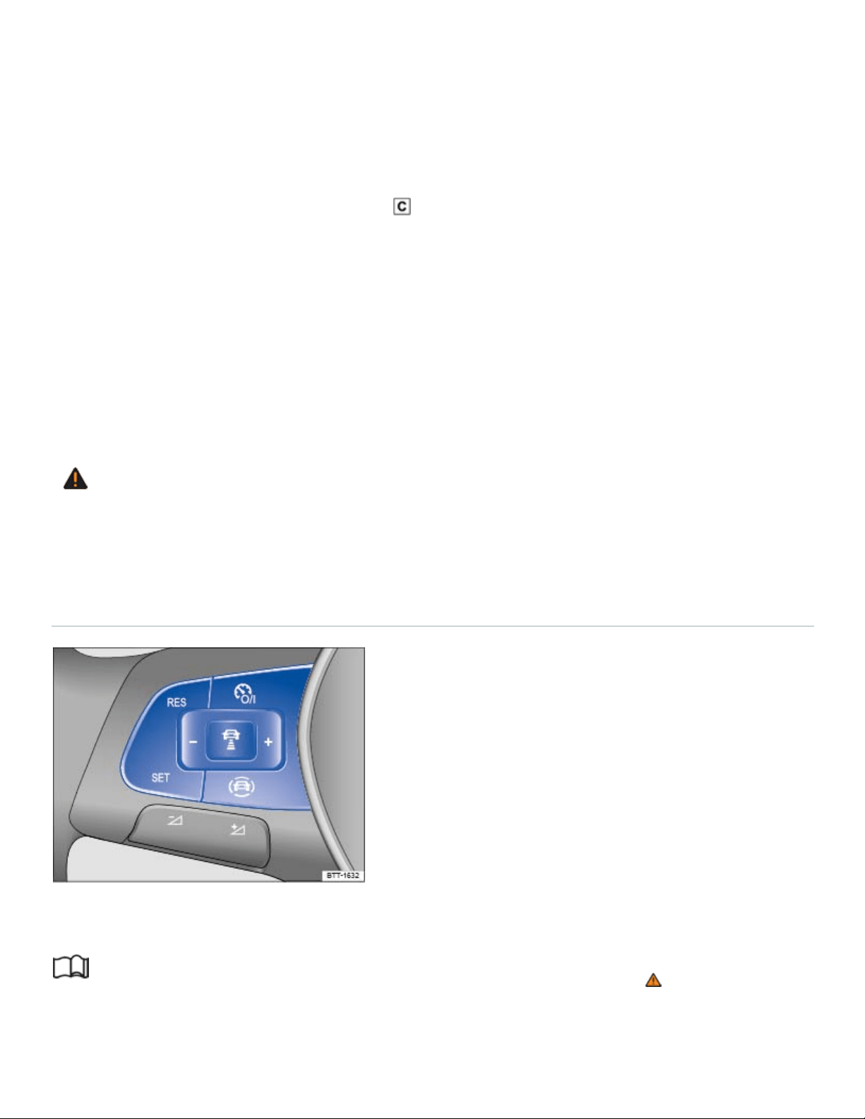
Narrow vehicles, such as motorcycles, traveling ahead of you are often detected late or not at all un‐
der some circumstances.
Other vehicles changing lanes
Vehicles that change into your lane within a short distance can only be detected by the radar sensor
once they are within sensor range ⇒Fig.125 . The result is a delayed reaction by the Adaptive
Cruise Control. If required, brake the vehicle yourself.
Vehicles with oversize loads or special equipment
Under certain circumstances, ACC will not correctly recognize vehicles carrying oversize loads or
loads that exceed the vehicle dimensions, like flatbed trailer trucks.
Switch off ACC when driving behind or while passing such vehicles. If required, brake the vehicle
yourself.
WARNING
Not deactivating Adaptive Cruise Control (ACC) in the situations mentioned above can cause col‐
lisions, other accidents, and serious personal injury.
Switching ACC on and off
Fig.126Left-hand side of the multi-function steering wheel: Buttons for operating the Adaptive Cruise
Control (ACC).
Read and follow the introductory information and safety information first⇒ Introduction to the
subject
Switching ACC on

Press the button.
ACC is switched on. The gray indicator light or comes on, ACC does not regulate.
Setting the current speed
Press the button when the vehicle is moving.
ACC saves the current speed and maintains the preset distance interval to the vehicle in front. If the
current speed is outside the defined speed range, ACC will set the minimum speed (when driving
more slowly than the minimum speed) or maximum speed (when driving faster than the maximum
speed).
Depending on the driving situation, the following indicator lights come on:
ACC is active.
No vehicle has been detected ahead.
Vehicle detected ahead.
Temporarily deactivating ACC
Briefly press the button on the multi-function steering wheel.
OR: Depress the brake pedal.
Depending on whether a vehicle is detected ahead, either the or indicator light stays on in the
instrument cluster display, and the speed and distance intervals stay stored.
When ASR is switched off, ACC is automatically deactivated.
Resuming ACC
Press the button.
ACC uses the most recently set speed and most recently set distance interval to the vehicle in front.
The instrument cluster display shows the set speed, and the green indicator light comes on.
Switching ACC off
Press and hold the button.
ACC is switched off and the stored speed is deleted.
Applicable only for the United States
Adjusting settings for ACC
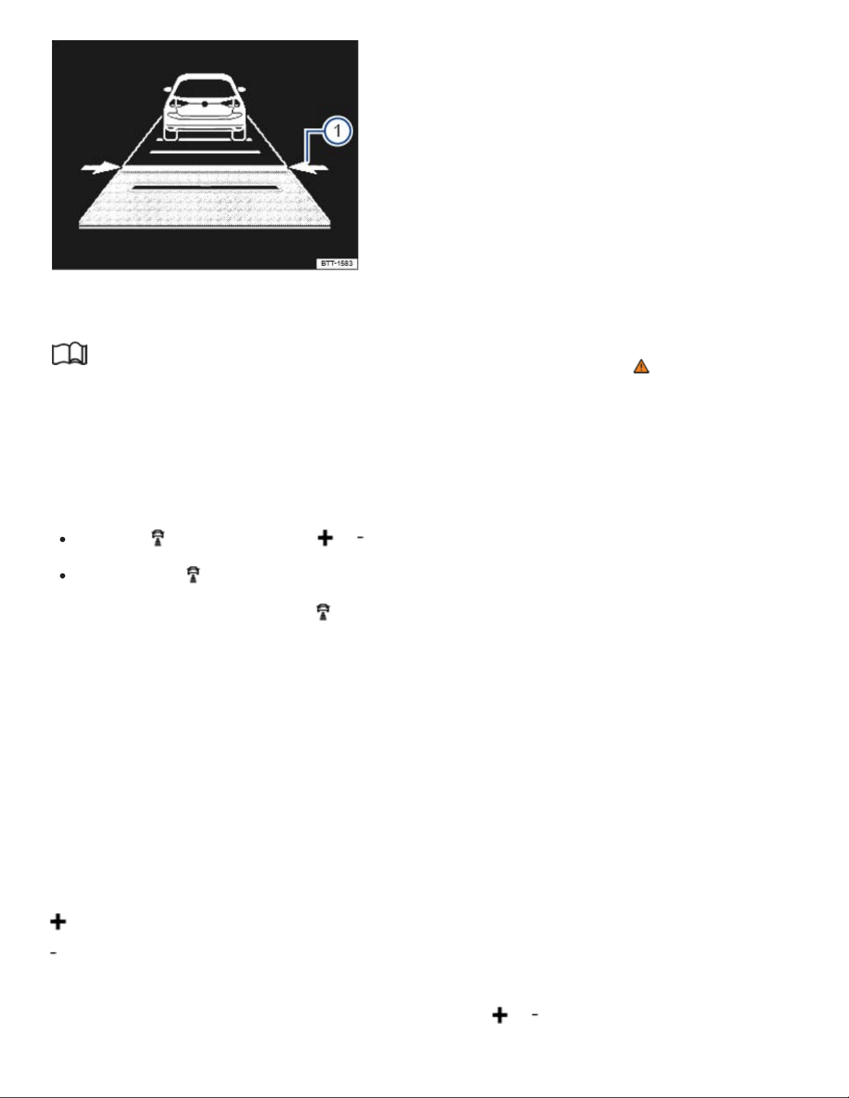
Fig.127In the instrument cluster display: distance interval is being set (displayed in color on an in‐
strument cluster with color display).
Read and follow the introductory information and safety information first⇒ Introduction to the
subject
Setting the distance interval
You can set the speed-dependent distance from the vehicle ahead to one of 5levels ranging from
very close to very far.
Press the button and then the or button on the multi-function steering wheel.
OR: Press the button until the required distance is set.
The ACC display appears when the button is pressed. The ACC display shows the current distance
interval ⇒Fig.127① .
If ACC is switched off, the set distance interval and the vehicle are not shown in the instrument cluster
display.
In wet road conditions, you should always set a larger distance than when driving in dry road
conditions.
Adjusting the set speed
You can set a speed within the defined speed range as follows by briefly pressing the buttons
on the multi-function steering wheel:
+1mph (1km/h)
-1mph (1km/h)
To adjust the stored speed continuously, press and holdthe or button.

Adjusting the driving mode or drive program
Vehicles with Driving Mode Selection: Set the driving mode ⇒4MOTION Active Control .
Vehicles without Driving Mode Selection: Set the drive program in the Infotainment system
⇒Infotainment system operation and displays .
WARNING
Following other vehicles too closely increases the risk of collisions and serious personal injury or
even death.
Always obey applicable traffic laws when setting the distance to the vehicles ahead in traffic.
Setting short distances to the traffic ahead reduces the time and distance available to bring
your vehicle to a safe stop and makes it even more necessary to pay close attention or traffic.
Always use good judgment and select a safe following distance for the traffic, road and
weather conditions.
Never use Adaptive Cruise Control on narrow or winding roads or under poor road conditions
(snow, ice, streets covered with standing water or gravel, for example) or when visibility is
poor, especially when it is foggy.
Always select a greater following distance to the vehicle ahead on wet roads than on dry
roads.
Tips and troubleshooting
Read and follow the introductory information and safety information first⇒ Introduction to the
subject
ACC not available
The yellow indicator light comes on.
The radar sensor is dirty. Clean the radar sensor ⇒Exterior care and cleaning .
Radar sensor visibility is impaired by weather conditions such as snow, or residue from abrasive
cleaning agents or coatings. Clean the radar sensor ⇒Exterior care and cleaning .
Radar sensor visibility is impaired by aftermarket components, stickers, or accessories.
The radar sensor has been damaged or misaligned in low speed impacts or parking maneuvers at
the front of the vehicle. Have the sensor checked for damage ⇒Repairs and technical modifica‐

tions .
ACC malfunction. Switch the engine off and on again.
Paint work or structural modifications have been made at the front of the vehicle.
The original Volkswagen emblem is not being used.
If the problem persists, see an authorized Volkswagen dealer or authorized Volkswagen Service
Facility.
If the system is not responding as expected
The radar sensor is dirty. Clean the radar sensor ⇒Exterior care and cleaning .
ACC is functioning in a situation in which it should be deactivated due to system limitations
⇒Limits of ACC .
The brakes are overheated from braking maneuvers or driving down steep slopes. A driver infor‐
mation message appears in the instrument cluster display. Allow the brakes to cool down and acti‐
vate ACC again.
If the problem persists, see an authorized Volkswagen dealer or authorized Volkswagen Service
Facility.
If ACC will not switch on
The selector lever is in position (D/S) or in Tiptronic mode.
The brake lights on the vehicle and trailer are working.
ESC is not regulating.
The brake pedal is not depressed.
If there are unusual noises during automatic braking
This is normal and is not a malfunction.
Forward Collision Warning (Front Assist)
Introduction to the subject
In this chapter you will find information on the following subjects:
⇒Driver warnings and Autonomous Emergency Braking

⇒System limits
⇒Pedestrian Monitoring
⇒Using Front Assist
⇒Tips and troubleshooting
The vehicle is equipped with Forward Collision Warning (Front Assist), which can warn the driver of a
possible collision with a vehicle on the road ahead, help prepare the vehicle for emergency braking,
assist with braking, and initiate automatic braking, within physical and technical limits of the system.
The timing of the warning varies depending on the traffic situation and the actions of the driver.
The Front Assist system is not a substitute for the driver's full concentration.
Driving with Front Assist
You can cancel Front Assist automatic braking interventions by steering or depressing the accelerator
pedal.
Automatic braking
The Front Assist system can, within system limits, slow your vehicle down to a standstill, but not keep
your vehicle stopped for a long time. If necessary, apply the vehicle brakes!
During an automatic braking maneuver, the brake pedal will feel harder.
Radar sensor
The Forward Collision Warning system, when switched on, uses a radar sensor to gather information
about the driving situation ⇒Front view .
Features included
Front Assist includes Autonomous Emergency Braking and a Pedestrian Monitoring system. These
systems are automatically activated when Front Assist is activated.
WARNING
The Front Assist system technology cannot overcome the laws of physics and system-related
limits. Do not allow the increased convenience Front Assist can provide tempt you into taking ex‐
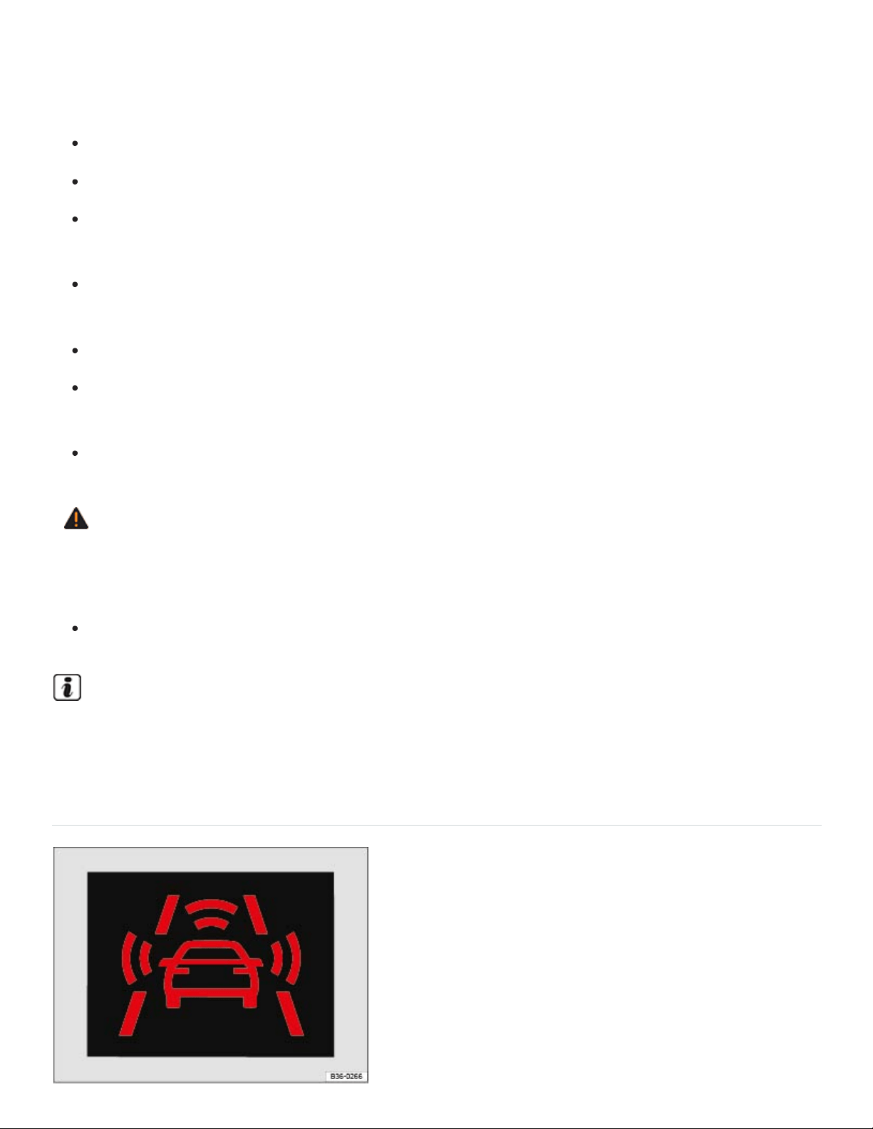
tra risks. The driver is always responsible for braking in time. If the Front Assist system issues a
warning, immediately apply the brake to slow the vehicle down or avoid the obstacle, depending
on the traffic situation.
Always adjust your speed and driving style to road, traffic, weather, and visibility conditions.
The Front Assist system cannot prevent accidents and serious injuries on its own.
The Front Assist system can issue unnecessary warnings in certain complex driving situations,
for example, when driving in tight curves.
The Front Assist system can issue unnecessary warnings when its function is impaired, for ex‐
ample, if the radar sensor is dirty or if the position of the radar sensor has been changed.
The Front Assist system does not react to animals.
The Front Assist system does not react to vehicles crossing your path or approaching in the
same lane.
Always be prepared to take full control of the vehicle at all times.
WARNING
Failure to heed warning lights and instrument cluster text messages can result in a collision and
serious personal injury.
Never ignore warning lights or text WARNINGS.
A Declaration of Compliance with the United States FCC and Industry Canada regulations is on
⇒Declaration of Compliance, Telecommunications and Electronic Systems .
Driver warnings and Autonomous Emergency Braking

Fig.128In the instrument cluster display: Advance warning.
Read and follow the introductory information and safety information first⇒ Introduction to the
subject
Pedestrians and vehicles, who are moving in the same direction as your vehicle.
Pedestrians who are crossing in front of your vehicle.
Stopped vehicles.
If you are approaching a detected object at a speed which will result in a collision and you do not act
immediately, Front Assist can help minimize the effects of a collision. First comes an advanced warn‐
ing, then an immediate warning, and finally an automatic braking maneuver.
Front Assist functions in these speed ranges:
Advance
warning
Immediate
warning
Automatic
braking
Braking support
Stopped vehicle
20 to 53 mph (30
to 85 km/h)
-
3 to 30 mph (5 to
50 km/h)
3 to 53 mph (5 to
85 km/h)
Vehicle moving
in the same
direction
20 to 155 mph
(30 to 250 kmh)
20 to 155 mph
(30 to 250 km/h)
3 to 155 mph (5
to 250 km/h)
3 to 155 mph (5 to
250 km/h)
Pedestrian mov‐
ing in the same
direction
20 to 40 mph (30
to 65 km/h)
- - -

Pedestrian
crossing in front
of the vehicle
20 to 40 mph (30
to 65 km/h)
-
3 to 40 mph (5 to
65 km/h)
-
The speed ranges given in the table are only in ideal situations and are approximations.
Advance warning
The system warns the driver with a warning chime and a message in the instrument cluster display
⇒Fig.128 if it detects a possible collision with a vehicle or a pedestrian.
The warning period varies according to the traffic situation and your driving style.
Brake or take action to avoid the vehicle ahead!
However, do not rely solely on Front Assist. Under certain conditions, the reactions of Front Assist
may be unexpected or delayed from the driver's viewpoint. Always pay attention and take over if nec‐
essary ⇒ .
Immediate warning
If you fail to react accordingly to the advance warning, Front Assist may initiate a short active braking
maneuver. In this case you will notice brief, jerky braking of the vehicle to warn you of an impending
collision.
The timing of this alert can vary, depending on the traffic situation and your driving style.
Automatic braking
If you should also fail to react to the immediate warning, Front Assist can initiate an automatic braking
maneuver that will abruptly decelerate the vehicle with an increased braking force. The emergency
braking maneuver occurs shortly before a potential collision to reduce vehicle speed and help to mini‐
mize the effects of a collision.
Braking support
Front Assist can help to minimize the effects of a collision by providing additional braking force in
case of an emergency braking situation should the system detect that the force applied to the brake
pedal by the driver is not sufficient to avoid a collision. In order for Front Assist to provide this addi‐
tional braking assistance, it must have detected an impending collision with another vehicle ahead of
yours and the brake pedal has to be hit hard and suddenly. However, this support only works as long
as the brake pedal is depressed.
Autonomous Emergency Braking
The Autonomous Emergency Braking system is a part of Front Assist. In case of an impending colli‐
sion, the Autonomous Emergency Braking system can initiate an automatic braking maneuver without
the advance or immediate warnings to reduce vehicle speed and help to minimize the effects of a col‐
lision ⇒ .
The automatic braking maneuver occurs simultaneously with a warning in the instrument cluster dis‐
play ⇒Fig.128 .
The red warning light comes on.
System deactivated
If the system is switched off, a text message and the yellow symbol appear in the instrument clus‐
ter display. The yellow central caution light may also light up.
Distance warning
If the vehicle is traveling within a speed range of about 40–155mph (65–250km/h), the system warns
the driver with the symbol in the instrument cluster display if it detects that your vehicle is
driving too close to the vehicle ahead ⇒ . No acoustic warning will sound.
The warning period varies according to the traffic situation and your driving style.
Increase the distance between your vehicle and the vehicle ahead.
System limits
Read and follow the introductory information and safety information first⇒ Introduction to the
subject
Front Assist has physical and system-related limits. You should always be prepared to take full control
of the vehicle whenever necessary.

Delayed response
If the radar sensor is exposed to environmental conditions that impair sensor function, the system
may detect this only after a certain delay. For this reason, possible functional restrictions may be dis‐
played only after a delay after you start driving and while driving ⇒ .
Objects that cannot be detected
Front Assist may react unnecessarily, react with delay, or not react at all in the following situations:
When vehicles or motorcycles are traveling slightly offset to the left or right in front of your vehicle.
When loads or attachment parts on other vehicles in front of your vehicle protrude to the side,
rear, or above the normal vehicle dimensions.
When there is oncoming traffic.
When vehicles are crossing in front of your vehicle.
When pedestrians are standing or moving toward you.
System limitations
Front Assist may react unnecessarily, react with delay, or not react at all in the following situations:
When driving in tight curves.
When weather conditions are poor.
When driving in parking garages.
When there are metal objects, for example, tracks or metal plates in the road.
When the vehicle is in Reverse (R).
When ASR or ESC is manually switched off.
When the ESC is taking corrective action.
When the off-road driving mode is switched on.
When the radar sensor is dirty or covered.
When several brake lights on the vehicle or on a trailer connected to the vehicle electrical system
are not working.
When the vehicle is accelerating quickly.
When the accelerator pedal is completely depressed.

When the system cannot detect the traffic situation clearly.
When there is a fault in the Front Assist system.
When to switch off Front Assist
Front Assist should be switched off in the following situations due to system limitations ⇒ :
If the vehicle is not being driven on public roads, for example, off-road or on a track.
If the vehicle is being towed.
If the vehicle is being loaded onto a truck, ferry, or train.
If the radar sensor is covered (even temporarily) by any accessories or other equipment, for ex‐
ample, auxiliary headlights.
If the radar sensor malfunctions.
If an external force has affected the radar sensor, for example, after a collision.
If the vehicle is on a dynamometer test bed.
WARNING
Failure to switch off Front Assist in the situations mentioned can cause accidents and serious
personal injury.
Pedestrian Monitoring
Read and follow the introductory information and safety information first⇒ Introduction to the
subject
The Forward Collision Warning system includes a Pedestrian Monitoring feature that can help prevent
accidents with pedestrians crossing the street or help minimize the outcome of an accident.
The system alerts you of an impending collision, prepares the vehicle for emergency braking, pro‐
vides support when braking, or performs an automatic braking maneuver.
If the system gives the driver an advanced warning, a message appears and the red warning light
comes on in the instrument cluster to warn the driver of an impending collision ⇒Driver warnings and
Autonomous Emergency Braking .

If the Front Assist system is switched on ⇒Using Front Assist , then Pedestrian Monitoring is also ac‐
tive within a speed range of about 3–40mph (5–65km/h).
WARNING
The Pedestrian Monitoring technology cannot overcome the laws of physics and system-related
limits. Never let the increased convenience provided by the Pedestrian Monitoring system tempt
you into taking extra risks. The driver is always responsible for braking in time. If the Pedestrian
Monitoring system issues a warning, immediately apply the brakes to slow the vehicle down or
avoid the pedestrian, depending on the traffic situation.
Always adjust your speed, driving style, and the distance you keep between you and the vehi‐
cles ahead of you to the road, traffic, weather, and visibility conditions.
The Pedestrian Monitoring system cannot prevent accidents and serious injuries on its own.
The Pedestrian Monitoring system can issue unnecessary warnings in certain complex driving
situations, for example, when driving in tight curves.
The Pedestrian Monitoring system can issue unnecessary warnings or braking maneuvers
when its function is impaired, for example, if the radar sensor is dirty or if the position of the
radar sensor has been changed.
The Pedestrian Monitoring system does not react to animals.
The Pedestrian Monitoring system does not react to pedestrians who are standing still or mov‐
ing toward you.
Always be prepared to take full control of the vehicle at all times.
Using Front Assist
Read and follow the introductory information and safety information first⇒ Introduction to the
subject
The Front Assist system and the advance warning are automatically active once the ignition is
switched on ⇒Starting and stopping the engine .
Volkswagen recommends that the Front Assist system be switched on at all times, except in the spe‐
cific situations described in this Manual ⇒System limits .
Turning Front Assist on or off

You can turn Front Assist on or off in the Vehicle settings menu in the Infotainment system
⇒Infotainment system operation and displays .
OR: In the Assist systems menu in the instrument cluster display ⇒Instrument cluster .
OR: Press the driver assistance systems button on the multi-function steering wheel to open the
Assist systems menu ⇒Driver Assistance systems button .
If the system is switched off, the advance warning and distance warning are also automatically
switched off. A text message and the yellow symbol appear in the instrument cluster display
⇒Driver warnings and Autonomous Emergency Braking . The yellow central caution light may also
light up.
Adjusting settings for the distance and advance warnings
You can turn the distance warning and the advance warning on or off in the Vehicle settings
menu in the Infotainment system ⇒Infotainment system operation and displays .
You can also adjust the warning period for the advance warning.
Volkswagen recommends that the distance and advance warnings be switched on at all times.
Certain settings are automatically saved by the driver personalization feature ⇒Driver
Personalization .
Tips and troubleshooting
Read and follow the introductory information and safety information first⇒ Introduction to the
subject
If Front Assist is unavailable or radar sensor visibility is insufficient
The radar sensor is dirty. Clean the radar sensor ⇒Exterior care and cleaning .
Radar sensor visibility is impaired by weather conditions such as snow, or residue from abrasive
cleaning agents or coatings. Clean the radar sensor ⇒Exterior care and cleaning .
Radar sensor visibility is impaired by aftermarket components, stickers, or accessories.
The radar sensor has been damaged or misaligned in low speed impacts or parking maneuvers at
the front of the vehicle. Have the sensor checked for damage ⇒Repairs and technical modifica‐
tions .
Paint work or structural modifications have been made at the front of the vehicle.

The original Volkswagen emblem is not being used.
ESC Sport is switched on ⇒Switching Anti-Slip Regulation (ASR) and ESC Sport mode on and
off .
If the problem persists, see an authorized Volkswagen dealer or authorized Volkswagen Service
Facility.
If the system is not responding as expected
The radar sensor is dirty. Clean the radar sensor ⇒Exterior care and cleaning .
Front Assist is functioning in a situation in which it should be deactivated due to system limitations
⇒Limits of ACC .
If the problem persists, switch off Front Assist see an authorized Volkswagen dealer or authorized
Volkswagen Service Facility.
NOTE
If you notice that Front Assist doesn't work properly or the sensor is damaged, switch off Front
Assist immediately.
See an authorized Volkswagen dealer or authorized Volkswagen Service Facility for assist‐
ance and have the Front Assist system checked.
Lane Keeping system (Lane Assist)
Introduction to the subject
In this chapter you will find information on the following subjects:
⇒Driving with Lane Assist
⇒Tips and troubleshooting
Your vehicle may be equipped with a Lane Assist system, which can warn you if your vehicle uninten‐
tionally leaves the current drive lane.
With the help of a camera ⇒Front view , Lane Assist can recognize certain lane markings for the lane
in which the vehicle is moving. Should the vehicle leave this area unintentionally, for example, when
leaving the lane without activating a turn signal, the system will warn you with a steering correction.
The driver can override the steering correction at any time.

Vehicles without Blind Spot Monitor⇒Blind Spot Monitor : Lane Assist will not warn you of a lane
change if you activate the turn signal, because the system will assume that the lane change is
intended.
System limits
Only use Lane Assist on highways and well-maintained roads.
Lane Assist may deactivate temporarily under certain circumstances:
When the speed of your vehicle is less than about 40mph (65km/h).
If the system cannot recognize lane markings correctly, for example, in construction zones, on bad
roads, when visibility is bad, or when the camera area is covered.
When ESC Sport mode is switched on (if equipped) ⇒Switching Anti-Slip Regulation (ASR) and
ESC Sport mode on and off .
WARNING
Always remember that Lane Assist has limits – using Lane Assist when it is not possible to drive
safely can be dangerous and can lead to an accident and serious personal injury.
Always adjust your speed and the distance you keep between you and the vehicles ahead of
you to the road, traffic, weather, and visibility conditions.
Always keep both hands on the steering wheel so that you are prepared to steer at any time.
The driver is always responsible for controlling the vehicle.
Always pay attention to the messages in the instrument cluster display and act accordingly.
Always pay close attention to what is happening around your vehicle.
WARNING
Not deactivating Lane Assist in the situations mentioned above can cause collisions, other acci‐
dents and serious personal injury.
Certain settings are automatically saved by the driver personalization feature ⇒Driver
Personalization .
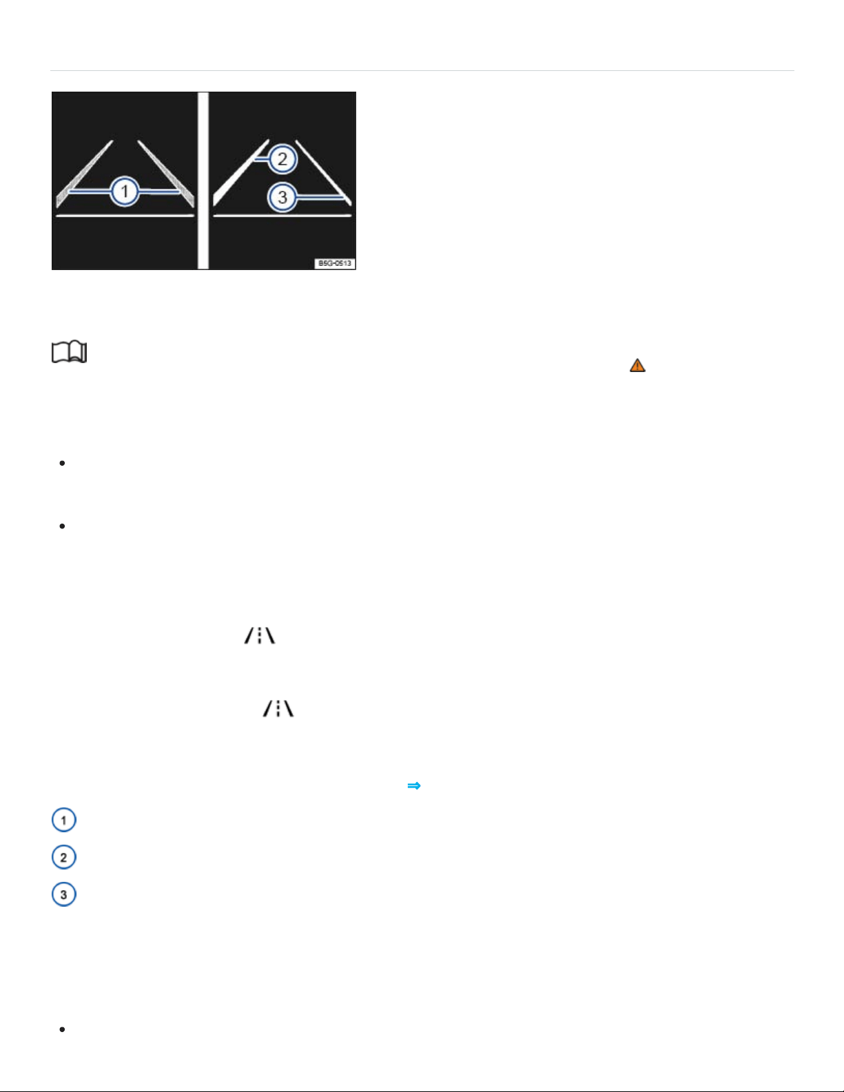
Driving with Lane Assist
Fig.129In the instrument cluster display: Lane Assist display (displayed in color on an instrument
cluster with color display).
Read and follow the introductory information and safety information first⇒ Introduction to the
subject
Switching Lane Assist on and off
You can turn Lane Assist on or off in the Vehicle settings menu in the Infotainment system
⇒Infotainment system operation and displays .
OR: Press the driver assistance systems button on the multi-function steering wheel to open the
Assist systems menu ⇒Driver Assistance systems button .
The indicator light in the instrument cluster shows the status of the system.
If the yellow indicator light comes on, Lane Assist is switched on but is not active.
Lane Assist works at speeds above about 40mph (65km/h) when lane markings can be identified
⇒ . The green indicator light comes on.
Displays
Lane Assist display in the instrument cluster ⇒Fig.129 :
Lane marking detected (shown in gray). System is not regulating.
Lane marking detected (shown in white). System is actively regulating.
No lane marking detected. System is not regulating.
Switching Lane Assist off temporarily
Lane Assist should be switched off in the following situations:
When driving with a sporty or dynamic driving style.

When bad weather conditions and/or visibility are poor.
When the vehicle is off road, for example, in construction zones or on race tracks.
Before the top of a hill.
Reminder to resume steering
If the system does not detect steering activity by the driver, a warning chime and a message in the in‐
strument cluster display remind you to resume steering the vehicle.
If the driver does not respond to the reminder, the system may deactivate temporarily.
Steering wheel vibration
Certain situations will cause the steering wheel to vibrate and demand active steering intervention by
the driver:
If the corrective steering intervention is not sufficient to keep the vehicle in its lane.
If the system no longer detects a lane during a strong corrective steering intervention.
WARNING
Failure to heed warning lights or other warnings can result in a collision and serious personal
injury.
Never ignore warning lights or text WARNINGS.
Always stop the vehicle as soon as it is safe to do so.
NOTE
Failure to heed warning lights or text WARNINGS can result in vehicle damage.
If there is a malfunction, Lane Assist is automatically deactivated.
Tips and troubleshooting
Read and follow the introductory information and safety information first⇒ Introduction to the
subject

If there is no camera image, an error message, or the system switches itself off
Clean the windshield ⇒Exterior care and cleaning .
Check for visible damage on the windshield in the camera's field of view.
If the system is not responding as expected
Regularly clean the camera and keep it free from snow and ice.
Do not cover the camera's field of view.
Check the windshield for damage in the camera's field of view.
Do not attach objects to the steering wheel.
WARNING
If the camera's field of view is covered or dirty, Lane Assist may not work properly.
Always make sure that the camera area is free of dirt or snow and not covered.
NOTE
In order to help keep Lane Assist working properly:
Always keep the windshield in front of the camera free of ice, dirt, snow, and other things that
could reduce its field of view.
Regularly check the windshield and especially the area around the camera for damage.
Never attach or mount any accessories or other items to the steering wheel.
If Lane Assist does not work properly and as described here or if there is a system fault, have the
system checked by an authorized Volkswagen dealer or authorized Volkswagen Service Facility.
Blind Spot Monitor
Introduction to the subject
In this chapter you will find information on the following subjects:
⇒Driving with Blind Spot Monitor

⇒Tips and troubleshooting
Depending on vehicle equipment, the vehicle may be equipped with the Blind Spot Monitor system.
The Blind Spot Monitor assists the driver by using radar sensors to monitor the traffic in the blind spot
detection area as well as traffic behind the vehicle. The system measures the distance and the speed
difference to the other vehicles around you. If the Blind Spot Monitor detects one or more vehicles in
the monitored area, indicator lights come on in the outside mirrors.
Physical and system limitations
The Blind Spot Monitor is only designed for use on paved roads.
In certain situations, the Blind Spot Monitor may not interpret the traffic situation correctly. These situ‐
ations may include:
When driving around sharp curves.
When driving between two lanes.
When the width of the lanes is not the same.
When driving at the top of a hill.
When the weather conditions are poor.
When certain types of equipment are on the side of the road, such as high or offset guard rails.
WARNING
The Blind Spot Monitor cannot overcome the laws of physics and limits of the system. Careless
or unintentional use of the Blind Spot Monitor may result in accidents and serious injuries.
The Blind Spot Monitor is not a substitute for careful and attentive driving.
Always adjust your driving style to road, traffic, weather, and visibility conditions.
Always keep both hands on the steering wheel so that you are prepared to steer at any time.
Pay attention to and heed the indicator lights in the outside mirrors and in the instrument clus‐
ter display.
The Blind Spot Monitor may react to certain equipment installed on the side of the road, such
as high or offset guardrails. False warnings may result.

Never use the Blind Spot Monitor on unpaved roads. The Blind Spot Monitor was designed
only for paved roads.
Always pay attention to the area surrounding your vehicle.
Never use the Blind Spot Monitor if the radar sensors are dirty, obstructed, or damaged; the
function of the system may be impaired.
Sunlight may reduce the visibility of the indicator light in the outside mirror.
If the system does not work as described in this chapter or if your vehicle was involved in a colli‐
sion, do not use the Blind Spot Monitor. See an authorized Volkswagen dealer or an authorized
Volkswagen Service Facility to have the system checked.
Certain settings are automatically saved by the driver personalization feature ⇒Driver
Personalization .
A Declaration of Compliance with the United States FCC and Industry Canada regulations is on
⇒Declaration of Compliance, Telecommunications and Electronic Systems .
Driving with Blind Spot Monitor
Fig.130In the outside mirrors: Indicator lights for the Blind Spot Monitor.
Read and follow the introductory information and safety information first⇒ Introduction to the
subject
Switching the Blind Spot Monitor on and off

You can turn the Blind Spot Monitor on or off in the Vehicle settings menu in the Infotainment
system ⇒Infotainment system operation and displays .
OR: In the Assist systems menu in the instrument cluster display ⇒Instrument cluster menus .
OR: Press the driver assistance systems button on the multi-function steering wheel to open the
Assist systems menu ⇒Driver Assistance systems button .
When the Blind Spot Monitor is switched on, the indicator lights in the outside mirrors light up to
confirm that the Blind Spot Monitor is ready.
The last system setting is stored when the ignition is switched off/on.
Blind Spot Monitor function
When switched on, the Blind Spot Monitor works at speeds above about 10mph (15km/h). The sys‐
tem switches off automatically at vehicle speeds below about 5mph (10km/h).
In the following situations, the yellow indicator light comes on in the respective outside mirror
⇒Fig.130 :
If your vehicle is being passed by another vehicle.
When passing another vehicle, and the difference in speed between the two vehicles is no more
than about 6mph (10km/h). There is no signal if the passing speed is clearly faster.
If you switch on the turn signal and the yellow indicator light flashes, the system detects a possible
critical situation on the corresponding side of the vehicle.
The faster another vehicle approaches, the earlier the signal in the outside mirror appears.
Active Blind Spot Monitor
For vehicles with Lane Keeping System (Lane Assist)⇒Lane Keeping system (Lane Assist) : When
Lane Assist is active, the driver will be warned of a critical situation during a lane change with a steer‐
ing correction. This happens even if the turn signal is switched on. If the driver ignores the steering
correction, the steering wheel will vibrate as an additional warning.
Blind Spot Monitor automatic deactivation
The radar sensors for the Blind Spot Monitor switch off automatically if the system detects an obstruc‐
tion over a radar sensor. This could occur if the radar sensor area is covered by ice or snow, for
example.

A text message appears in the instrument cluster display when the system turns off automatically.
If a Blind Spot Monitor sensor has been automatically deactivated, the system cannot be reactivated
until the ignition has been switched off and back on again.
Trailer towing
When the factory-installed trailer hitch is electrically connected with a trailer, the Blind Spot Monitor
turns off automatically. A text message appears in the instrument cluster display. After the trailer has
been removed, the Blind Spot Monitor may need to be manually reactivated.
If a trailer hitch is not factory-installed, the Blind Spot Monitor with must be manually turned off.
Radar sensors
The radar sensors are behind the rear bumper on the left and right. They are not visible from outside
the vehicle. They monitor an area about 21yards (20meters) behind the vehicle as well as the blind
spots on the left and right sides of the vehicle. The monitored area next to the vehicle is about one
lane wide.
The width of the lane is not detected individually on each road, but is preprogrammed into the system.
Because of this, the indicators may be incorrect when driving on narrow roads or driving in the center
of two lanes. Vehicles that are two lanes away from you or stopped objects such as guard rails may
also be detected and cause a false warning.
Tips and troubleshooting
Read and follow the introductory information and safety information first⇒ Introduction to the
subject
If the system malfunctions
Clean the sensors or remove stickers or accessories from the sensors and cameras ⇒Exterior
care and cleaning .
Check for any visible damage.
If the system is not responding as expected
The sensors are dirty ⇒Exterior care and cleaning . The sensors may not work properly if blocked
by dirt and snow or residue from abrasive cleaning agents or coatings.
The conditions for system operation are not met ⇒Physical and system limitations .

The sensors are covered by water.
The sensors have been damaged or misaligned in low speed impacts or parking maneuvers ⇒ .
The system function is impaired by an aftermarket component such as a bicycle rack.
A sensor area has been repainted or structural modifications have been made ⇒ .
The side windows have been tinted.
NOTE
The radar sensors in the rear bumper can be damaged or become misaligned in low-speed
impacts and parking maneuvers. The system can switch itself off or may be impaired as a
result.
Always keep the rear bumper clean and free of snow and ice so that the radar sensors can
work properly. Do not cover the radar sensor area.
The rear bumper may only be painted with vehicle paint that is approved by Volkswagen.
Other paints may make the Blind Spot Monitor system work improperly or cause it to
malfunction.
If the system does not work as described in this chapter or if your vehicle was involved in a colli‐
sion, do not use the Blind Spot Monitor system. See an authorized Volkswagen dealer or an au‐
thorized Volkswagen Service Facility to have the system checked.
Parking and maneuvering
Parking
Please note legal regulations when stopping and parking your vehicle.
Parking the vehicle
Please perform these steps only in the order listed:
Stop the vehicle on a suitable surface ⇒ .
Press the brake pedal and bring the vehicle to a complete stop. Leave your foot on the brake
pedal and continue to hold it down.

Shift the transmission into Park (P).
Apply the electronic parking brake to help prevent the vehicle from moving ⇒Electronic parking
brake . Make sure that the yellow indicator light in the button comes on.
Make sure that the red indicator light or in the instrument cluster lights up.
Switch off the engine and then take your foot off the brake pedal.
If necessary, remove the vehicle key from the ignition.
If necessary, turn the steering wheel slightly to engage the steering column lock.
Make sure all passengers and especially children leave the vehicle.
Take all vehicle keys with you when leaving your vehicle.
Lock the vehicle.
On hills
Before switching off the engine, turn the steering wheel so that, if the vehicle starts to roll, its front
wheels will roll into the curb:
Facing downhill, turn the front wheels so that they point toward the curb.
Facing uphill, turn the front wheels so that they point away from the curb.
WARNING
The vehicle exhaust system and the catalytic converter get very hot. They can cause fires and
serious personal injury.
Never park where the hot exhaust system could ignite flammable materials, such as brush,
leaves, dry grass, spilled fuel, etc.
WARNING
Leaving the vehicle when the selector lever is not in Park (P) can cause the vehicle to roll away.
This can cause accidents and serious personal injuries.
Always follow the correct order to stop the engine ⇒Starting and stopping the engine
When leaving the vehicle, always move the selector lever to Park (P), engage the electronic
parking brake, and pay attention to the warning messages in the instrument cluster display at
all times.

WARNING
Driving with bad brakes or worn brake pads can cause a collision and serious personal injury.
If the brake pads are worn, you notice changes in the way the vehicle brakes, or the warning
light appears in the instrument cluster immediately contact an authorized Volkswagen
dealer or authorized Volkswagen Service Facility to have the brake pads checked and, if nec‐
essary, replaced.
WARNING
Parking improperly can cause serious personal injury.
Never remove the key from the ignition switch or turn off the ignition with the starter button
while the vehicle is moving or rolling to a stop. The electronic steering column could suddenly
lock, you would not be able to steer, and you could lose control of the vehicle, crash, and seri‐
ously injure yourself and others.
Never park the vehicle where the hot exhaust system or catalytic converter could ignite
flammable materials, such as brush, leaves, dry grass, spilled fuel, etc.
Always apply the parking brake when parking your vehicle.
Improper use of the parking brake can seriously injure you and your passengers.
Never use the parking brake to slow down the vehicle when it is moving, except in an emer‐
gency. The stopping distance is much longer because only the rear wheels are braked. Always
use the foot brake to stop the vehicle.
Never activate the throttle manually from the engine compartment when the engine is running
and the automatic transmission is in gear. The vehicle will start to move as soon as the engine
speed increases even if the parking brake is on.
Never leave children or anyone who cannot help themselves behind in the vehicle. They could
release the parking brake and move the gear selector lever or gear shift, which could cause
the vehicle to start moving. This can lead to a crash and serious personal injuries.
Always switch off the engine and the ignition and take the key with you when you leave the ve‐
hicle. If the key is available, the engine can be started and vehicle systems such as the power
windows can be operated, leading to serious personal injury.
Never leave children, disabled persons, or anyone who cannot help themselves in the vehicle.
The doors can be locked with the remote control vehicle key, trapping passengers in the vehi‐
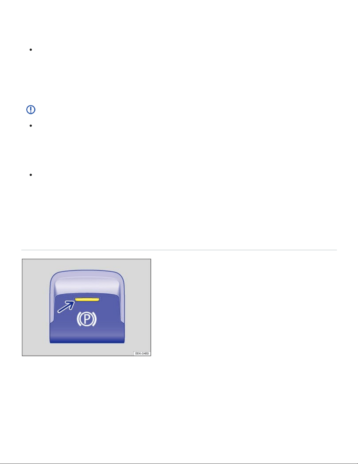
cle in an emergency. For example, depending on the time of year, people trapped in the vehi‐
cle can be exposed to very high or very low temperatures.
Heat buildup in the passenger and luggage compartment of a parked vehicle can result in tem‐
peratures in the vehicle that are much higher than the outside temperatures, particularly in
summer. Temperatures can quickly reach levels that can cause unconsciousness and death,
particularly to small children.
NOTE
Always be careful when you park in areas with parking barriers or high curbs. These vary in
height and could damage your bumper and related parts if the front of your vehicle hits a bar‐
rier or curb that is too high while you are getting into or out of a parking spot. To help prevent
damage, stop before the tires of your vehicle touch a parking barrier or curb.
Always be careful when you enter a driveway or drive up or down steep ramps or over curbs
or other obstacles. Parts of the vehicle close to the ground may be damaged (such as bumper
covers, spoilers, and parts of the engine, suspension, and exhaust systems).
Electronic parking brake
Using the electronic parking brake
Fig.131In the lower center console: Electronic parking brake switch.
Setting the electronic parking brake
You can engage the electronic parking brake any time the vehicle is not moving - even if the ignition is
switched off. Always shift the transmission to park (P) and engage the parking brake when you leave
or park the vehicle ⇒Parking .

Pull and hold the switch ⇒Fig.131 until the yellow indicator light in the switch comes on.
The parking brake is engaged when the yellow indicator light in the switch ⇒Fig.131 (arrow) and
the red indicator light or in the instrument cluster light up.
Releasing the electronic parking brake
Switch the ignition on.
Depress the brake pedal firmly and press the switch ⇒Fig.131 .
OR: If the engine is running, press the accelerator pedal lightly without pressing the brake pedal.
The parking brake is released when the yellow indicator light in the switch ⇒Fig.131 (arrow) and
the red indicator light in the instrument cluster ⇒Warning and indicator lights go out.
Automatic electronic parking brake release when you start driving
The electronic parking brake releases automatically when you start driving if the driver door is closed.
Using the electronic parking brake when starting on a hill or with a heavier load.
You can prevent the electronic parking brake from switching off automatically by pulling and holding
the switch while pulling away.
The electronic parking brake is only switched off after you let go of the switch.
This makes it easier to start off with a heavier load on a trailer.
Automatic electronic parking brake activation when the driver leaves the vehicle
The electronic parking brake can automatically switch on when the driver leaves the vehicle to help
prevent the vehicle from moving if the system detects that it is necessary.
Emergency braking feature
Only use the emergency braking feature in an emergency, when you cannot stop the vehicle using
the brake pedal ⇒ !
Pull and hold the switch ⇒Fig.131 to brake the vehicle hard. An audible warning signal will
sound at the same time.
WARNING
Improper use of the electronic parking brake can cause accidents and severe injuries.

Never use the parking brake to slow down the vehicle when it is moving, except in an emer‐
gency. Braking distance is much longer, since only the rear wheels are braked. Always use the
foot brake.
Never press the accelerator pedal when a selector lever position or gear is engaged and the
engine is running. The vehicle could begin moving, even if the electronic parking brake is set.
Never activate the throttle manually from the engine compartment when the engine is running
and the automatic transmission is in gear. The vehicle will start to move even if the parking
brake is engaged.
NOTE
Even though the transmission is in Park (P), the vehicle may move a couple of inches (a few cen‐
timeters) forwards or backwards if you take your foot off the brake pedal after stopping the vehi‐
cle without first firmly setting the parking brake.
Tips and troubleshooting
When the ignition is switched on, several warning and indicator lights come on briefly for a function
check. They go out after a few seconds.
or The electronic parking brake is switched on
The red warning light comes on.
or The electronic parking brake does not have enough holding force for the current
situation
The red warning light flashes.
Find another place to park the vehicle.
Pull and hold the electronic parking brake switch until you start driving.
There is an electronic parking brake malfunction
The yellow indicator light comes on. See an authorized Volkswagen dealer or an authorized
Volkswagen Service Facility.
If the electronic parking brake does not switch off
The conditions for releasing the electronic parking brake are not met.

OR: The 12Volt vehicle battery is dead.
Check whether all conditions for releasing the electronic parking brake are met ⇒Using the elec‐
tronic parking brake .
If the 12Volt vehicle battery is dead, the electronic parking brake cannot be released. Jump-start
the vehicle instead ⇒Jump-starting .
If the electronic parking brake makes noises
You may hear noises when setting or releasing the electronic parking brake. This is normal and no
cause for concern.
If the electronic parking brake is not used for some time, an automatic system check will occasion‐
ally run when the vehicle is parked. This system check makes audible noises.
WARNING
Failure to heed warning lights and instrument cluster text messages can result in a collision and
serious personal injury.
Never ignore warning lights or text WARNINGS.
Always stop the vehicle as soon as it is safe to do so.
Park Distance Control (PDC)
Introduction to the subject
In this chapter you will find information on the following subjects:
⇒Switching PDC on and off
⇒PDC signal chimes and displays
⇒Tips and troubleshooting
Depending on equipment, the vehicle may be equipped with the Park Distance Control system (PDC).
The Park Distance Control (PDC) system can help the driver when backing up and parking. PDC
uses ultrasonic sensors in the bumpers to measure the distance between the vehicle and objects.
The system uses the time it takes for the ultrasonic waves to bounce back from the object to calculate

the distance between the vehicle and an object. PDC works only at speeds up to about 5–10mph
(10–15km/h).
If the vehicle gets too close to an obstacle behind it, a beeping signal sounds. The closer the vehicle
gets to the obstacle, the faster the beep. When the obstacle is very close, the sound is continuous.
If you move even closer to the obstacle despite the continuous warning sound, the system cannot
measure the distance remaining until collision.
WARNING
Park Distance Control is no substitute for careful and attentive driving. Never rely completely on
these systems for information about people and objects that might be in the way of the vehicle
and could be struck resulting in serious personal injuries.
Always be careful and look around you when parking. The sensors have blind spots and can‐
not always detect people, animals, and objects. Watch out for small children and animals in
particular.
Certain types of clothing and the surfaces of certain objects do not reflect the ultrasonic waves
that the sensors send and receive. Such objects and persons wearing such clothing will not be
detected by PDC or will not be detected accurately.
Noise in the area can interfere with the signals of the Park Distance Control sensors. Under
certain circumstances, the system will not detect people and objects for this reason.
NOTE
Things like trailer draw bars, thin rods, fences, trees, narrow painted vertical poles, posts, or a
trunk lid that is opening may not be detected by the Park Distance Control sensors and could
damage the vehicle.
If you keep driving closer to an object that the Park Distance Control has already detected and
reported, the object may disappear from the sensor range and may no longer be detected.
This is especially true for low or high objects. The system will no longer sound warnings about
these objects. Ignoring signals from the Park Distance Control system could result in serious
damage to the vehicle.
The sensors in the bumpers can be damaged or become misaligned in low speed impacts and
parking maneuvers. Damaged or misaligned sensors cannot accurately detect or report ob‐
jects that might be within range of the PDC system.
To help make sure that the system works properly, always keep the sensors in the bumpers
clean and free of snow and ice; do not cover the sensors with stickers or other objects.
Repainting the sensors in the bumpers can impair the function of the PDC system.
When cleaning the sensors with power washers or steam cleaners, only spray the sensors di‐
rectly for a very short time, and always keep the washer nozzle at least 4inches (10cm) from
the sensors.
Noise from rough roads, cobblestones, other vehicles and the surrounding area, for example,
can prevent the Park Distance Control system from accurately detecting and reporting people
and objects that may be within range of the sensors.
Aftermarket components such as bicycle racks can impair the function of the Park Distance
Control system.
Volkswagen recommends practicing with the Park Distance Control system in a location or park‐
ing space with no traffic in order to become familiar with the system and how it works.
Certain settings are automatically saved by the driver personalization feature ⇒Infotainment sys‐
tem operation and displays .
A Declaration of Compliance with the United States FCC and Industry Canada regulations is on
⇒Declaration of Compliance, Telecommunications and Electronic Systems .
Switching PDC on and off
Fig.132In the lower center console: Button to switch the Park Distance Control system on or off
(Vehicles without Area View).

Fig.133In the lower center console: Button to switch the Park Distance Control system on or off (ve‐
hicles with Area View).
Read and follow the introductory information and safety information first⇒ Introduction to the
subject
The intermittent and continuous signal chimes triggered by the front PDC sensors have a higher pitch
than those from the rear PDC sensors. This is a standard feature.
The warning signals can be adjusted in the Infotainment system menu ⇒Infotainment system opera‐
tion and displays .
Switching Park Distance Control (PDC) on
Press the or button ⇒Fig.132 , or ⇒Fig.133 .
PDC is automatically switched on when you shift into reverse (R) or when the vehicle rolls backwards.
The indicator light in the button lights up and stays on as long as PDC is active.
In some vehicles, PDC can also be set to activate automatically when the vehicle moves forward
⇒Automatic PDC activation when driving forward (depending on equipment) .
Switching Park Distance Control (PDC) off
Press the or button ⇒Fig.132 , or ⇒Fig.133 .
OR: Drive forward faster than about 5–10mph (10–15km/h).
OR: Move the selector lever to park (P).
Automatic PDC activation when driving forward (depending on equipment)
When the PDC is activated automatically when driving forward, a mini PDC display appears on the
left-hand side of the screen.

Automatic PDC activation when driving forward only works when the speed falls below about 10mph
(15km/h) when driving slowly toward an obstacle in front of the vehicle. Automatic PDC activation
when driving forward can be turned on or off in the Infotainment system ⇒Infotainment system oper‐
ation and displays .
Automatic activation only happens once. Reactivate the PDC with one of the following actions when
the ignition is switched on:
Press the or button.
Switch the ignition off and back on again.
Move the selector lever to park (P) and then to reverse (R).
Switch the electronic parking brake on and off again.
Maneuver braking
The maneuver braking feature can help the driver by braking automatically when the vehicle is back‐
ing up and an obstacle behind the vehicle is detected.
Depending on vehicle equipment, the maneuver braking feature may also brake automatically when
driving forward if PDC has been switched on manually.
The maneuver braking feature helps prevent collisions only at vehicle speeds lower than 5mph
(10km/h). Maneuver braking is activated or deactivated when PDC is switched on or off. After emer‐
gency braking occurs, the maneuver braking feature is deactivated until you move the selector lever
to another position. The same restrictions that apply to the PDC system also apply to the maneuver
braking feature.
The maneuver braking feature does not switch on if PDC is activated automatically. You must switch
on PDC manually by pressing the or button.
You can also switch maneuver braking on and off by tapping the function key in the PDC display.
Park Distance Control in custom offroad mode
If PDC is switched off in custom offroad mode, acoustic and visual warnings are switched off
⇒4MOTION Active Control . Depending on equipment, the camera image may still be displayed.
Closing the camera image ends all parking functions. PDC will not switch on automatically.
PDC signal chimes and displays
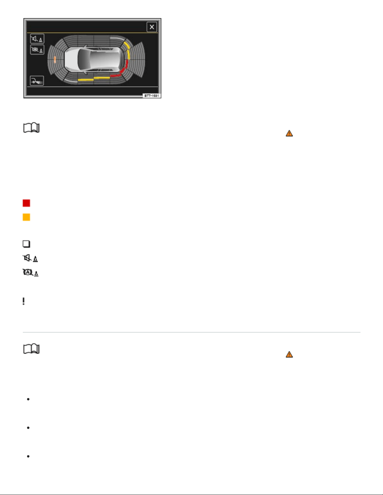
Fig.134PDC display of the area around the vehicle.
Read and follow the introductory information and safety information first⇒ Introduction to the
subject
When the factory-installed Infotainment system is switched on, the areas to the front and rear of the
vehicle that are scanned by ultrasonic sensors are shown on the screen ⇒Fig.134 . The positions of
potential obstacles are displayed relative to the vehicle.
Obstacle close to the vehicle. A continuous chime sounds. Stop! Do not keep driving!
Obstacle in the vehicle’s path. An intermittent chime sounds. The shorter the distance, the
shorter the intervals between the chimes.
Obstacle outside of the vehicle's path.
Switch the PDC sound on or off.
Switch maneuver braking on or off (depending on equipment).
Switch to the Rear View Camera system display (depending on equipment).
Malfunction in the scanned area. The color can vary.
Tips and troubleshooting
Read and follow the introductory information and safety information first⇒ Introduction to the
subject
If the system is not responding as expected
The sensors are dirty ⇒Exterior care and cleaning . The sensors may not work properly if blocked
by dirt and snow or residue from abrasive cleaning agents or coatings.
The conditions for automatic PDC activation are not met ⇒Automatic PDC activation when driving
forward (depending on equipment) .
When a trailer is electrically connected to the factory-installed trailer hitch on the vehicle, only the
front part of the PDC display is shown.

The sensors have been damaged or misaligned in low speed impacts or parking maneuvers.
Damaged or misaligned sensors cannot accurately detect or report objects that might be within
range of the PDC system.
The system function is impaired by an aftermarket component such as a bicycle rack.
A sensor area has been repainted or structural modifications have been made.
The sensors may not detect people and objects due to noise interference from rough roads, cob‐
blestones, other vehicles, and the surrounding area.
If there is no sensor visibility, an error message appears, or the system switches itself off
If an ultrasonic sensor malfunctions, the corresponding sensor area is switched off and cannot be re‐
activated until the malfunction is corrected.
If you hear a long beep of about 3seconds when you first turn PDC on or the indicator light in the
or button starts blinking, there is a malfunction in the Park Distance Control system.
A message may also appear in the instrument cluster display, depending on equipment.
Possible solutions
Switch the system off temporarily.
Check whether any of the causes described in this section apply.
Clean the sensors or remove stickers or accessories from the sensors and cameras ⇒Exterior
care and cleaning .
Check for any visible damage.
After checking all the possible causes and making the necessary adjustments, switch the system
back on.
If the system still does not respond as expected, have it checked by an authorized Volkswagen
dealer or an authorized Volkswagen Service Facility.
Rear View Camera system
Introduction to the subject
In this chapter you will find information on the following subjects:
⇒Switching the Rear View Camera system on and off

⇒Rear View Camera system display
⇒Requirements
⇒Perpendicular parking
⇒Parallel parking
⇒Tips and troubleshooting
There is a camera in the trunk lid to assist the driver while backing up or maneuvering. The camera
image is shown together with the orientation lines projected by the system on the screen of the fac‐
tory-installed Infotainment system.
The Rear View Camera system may take a couple of seconds to bring up the camera image.
Rear View Camera System modes (if equipped)
The functions and displays of the Rear View Camera system may vary.
Perpendicular parking: Backing into a perpendicular parking space ⇒Perpendicular parking .
Parallel parking: Backing into a parallel parking space ⇒Parallel parking .
Trailer support or offroad support: Helps when hooking up a trailer to the trailer hitch or when
driving offroad ⇒Switching the Rear View Camera system on and off .
Cross traffic: Helps the driver to see traffic behind the vehicle ⇒Switching the Rear View
Camera system on and off .
WARNING
The Rear View Camera system is not able to give you a clear and undistorted view of all areas
behind the vehicle.
The camera lens can enlarge and distort the field of view and can cause objects on the screen
to appear altered and imprecise.
Due to the screen resolution or in low-light conditions, the camera may not pick up thin posts,
chain-link fences and similar fences, and other objects, or it may not show them clearly.
Always be careful and look around you when parking. The Rear View Camera system has
blind spots and cannot always show people, animals, and objects in certain situations. Watch

out for small children and animals in particular.
Always keep the camera lens clean and free of snow and ice; do not cover the lens.
WARNING
The Rear View Camera system technology cannot overcome the laws of physics and the limits of
the system. Careless or unintentional use of the Rear View Camera system may result in acci‐
dents and severe injuries.
Always adjust your speed and driving style to road, traffic, weather, and visibility conditions.
Always keep an eye on the parking direction and the vehicle surroundings. The front of the ve‐
hicle swings out more than the rear of the vehicle.
Never pay so much attention to the images on the screen that you fail to notice what is going
on around you.
Use the Rear View Camera system only when the trunk lid is completely closed.
NOTE
The Rear View Camera system shows only two-dimensional images on the screen. Due to the
lack of depth of field, it may be difficult or impossible to identify protruding objects or potholes
in the road, for example.
Things like thin rods, fences, posts, and trees may not be shown by the Rear View Camera
system and could damage the vehicle.
NOTE
The orientation lines are displayed independent of the area around the vehicle. There is no auto‐
matic detection of obstacles. The driver is responsible for judging if the vehicle fits into the park‐
ing spot.
Volkswagen recommends practicing with the Rear View Camera system in a location or parking
space with no traffic in order to become familiar with the system and how it works.
Switching the Rear View Camera system on and off

Read and follow the introductory information and safety information first⇒ Introduction to the
subject
Switching the Rear View Camera system on
Switch the ignition on.
Shift into Reverse (R). The perpendicular parking mode will be displayed in the Infotainment
system.
OR:For vehicles with Park Distance Control: if the full-screen PDC display is on, move your hand
toward the screen and tap the function key ⇒Park Distance Control (PDC) .
The camera image will be displayed with the orientation lines. The Rear View Camera system func‐
tions keys are not shown. This helps the driver to have an unobstructed view of the area behind the
vehicle.
To access the full functionality of the Rear View Camera system, tap the function key MENU in the
top left hand corner of the screen. The function keys will now appear on the screen.
Switching the Rear View Camera system off
Switch off the ignition
OR: Drive forward faster than about 10mph (15km/h) or for longer than 10seconds.
OR: Shift out of Reverse (R). Depending on equipment, the display may take up to 10seconds to
switch off.
OR: Press one of the Infotainment system buttons or move your hand toward the screen and tap
the function key.
OR:For vehicles with PDC: Move your hand toward the screen and tap the function key to
select the full-screen PDC display ⇒Park Distance Control (PDC) .
Rear View Camera system display
Read and follow the introductory information and safety information first⇒ Introduction to the
subject
Function keys and displays may vary, depending on vehicle equipment.
Rear View Camera system function keys

x
The following function keys appear when you tap the MENU function key on the screen or
move your hand toward the screen.
Close the current display.
Switch to perpendicular parking.
Switch to parallel parking mode.
Switch to trailer support or offroad support mode
Switch to cross traffic mode.
Adjust the display brightness, contrast, and color.
Show the full-screen PDC display.
Switch the PDC display on.
Switch the PDC display off.
Turn the steering wheel (in parallel parking mode).
Stop moving (in parallel parking mode).
Orientation lines
Horizontal red line: The safety distance, which is the area up to about 16inches (40cm) on the road
behind the vehicle.
Horizontal green line: Vehicle extension (somewhat wider) toward the rear. The green lines stop
about 6feet (2meters) on the road behind the vehicle.
Yellow lines: Vehicle path, depending on the angle of the steering wheel.
Yellow boxes: Front and rear boundaries for the parking space (in parallel parking mode).
Side green lines: Turning point when driving into a parking space (in parallel parking mode).
Red and green frames: Shape of the vehicle (in parallel parking mode).
All references to orientation line length apply to vehicles on a horizontal surface.
The angles of the red and green lines do not change when turning the steering wheel.
Trailer support (mode 3)

In vehicles with a factory-installed trailer hitch: the trailer support feature can be used when approach‐
ing a trailer you wish to tow. This mode uses a high zoom to display the area immediately behind the
vehicle. Obstacles behind the vehicle appear in the field of view later than in other modes. You must
therefore pay very close attention.
The semi-circular green and red lines indicate the distance from the towing hitch.
Red line: The horizontal red line shown on the screen is level with the towing hitch. The distance
from the vehicle is about 1.3 feet (0.4 m).
Green semi-circle: The distance from the vehicle. The distance between each semi-circle is approxi‐
mately 4 in (10 cm).
Orange line: The predicted path of the towing hitch, depending on the steering angle.
Off-road support (mode 3)
In vehicles without a factory-installed trailer hitch: The off-road support mode can be used when driv‐
ing off-road, for example, when backing up. This mode uses a high zoom to display the area immedi‐
ately behind the vehicle. The horizontal red line shown on the screen is level with the rear of the vehi‐
cle. The distance between the vehicle and the red line is about 1.3 feet (0.4 m).
Cross-traffic
This mode displays a wide angle view of the area behind the vehicle. Cross-traffic mode helps the
driver to monitor traffic behind the vehicle and can be used in situations such as backing out of a
garage or pulling out of a narrow parking space.
The orientation lines are displayed independent of the area around the vehicle. There is no auto‐
matic detection of obstacles. The driver is responsible for deciding if the vehicle fits into the park‐
ing spot.
Requirements
Read and follow the introductory information and safety information first⇒ Introduction to the
subject
The following requirements must be met for parking while using the Rear View Camera system:
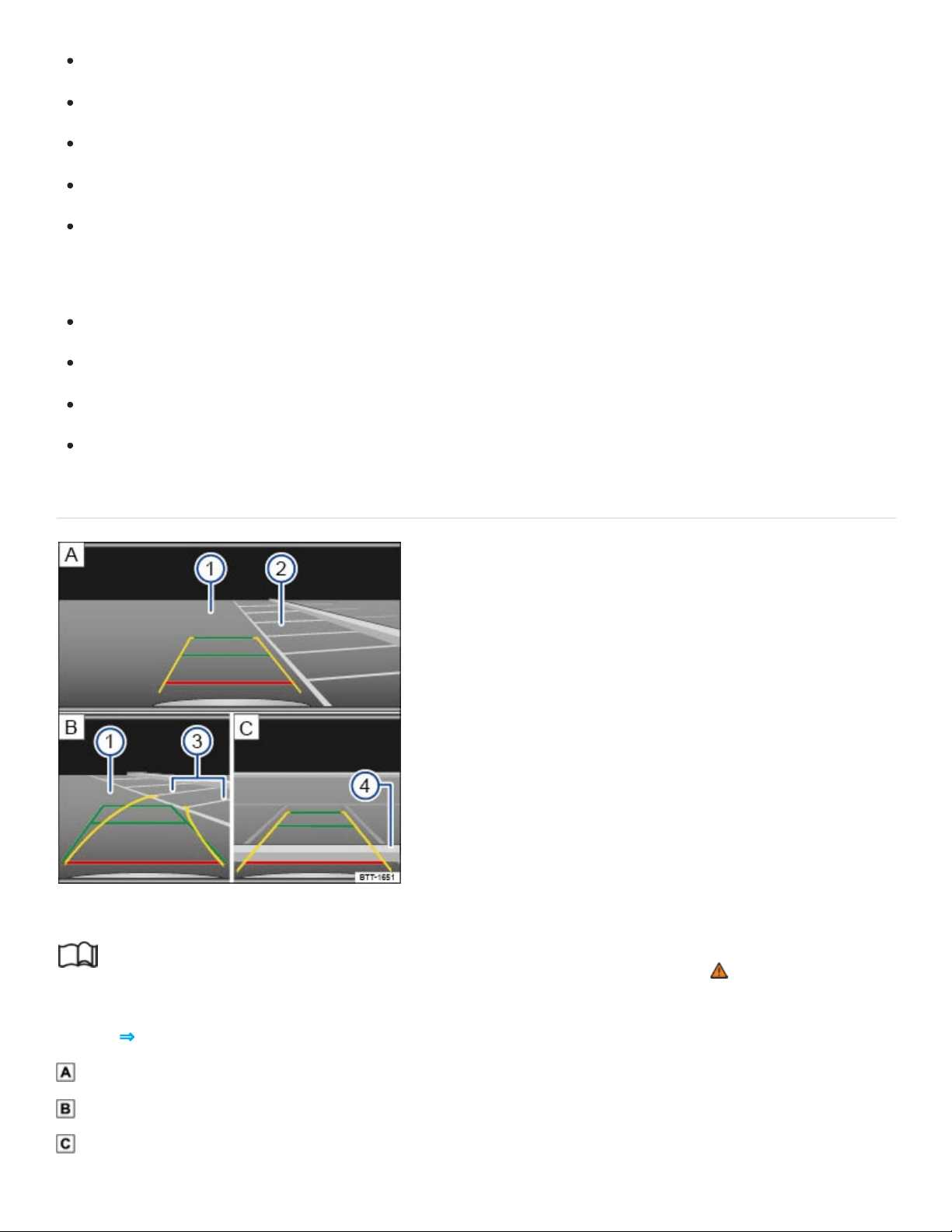
The vehicle speed must not be greater than about 10mph (15km/h).
The driver must be familiar with the system.
The width of the parking space must be at least the vehicle width +8inches (20cm).
Maintain a distance of about 3feet (1meter) from the parking space (parallel parking only).
The length of the parking space must be about 8yards (8meters) (parallel parking only).
The following conditions must be met to display a correct image:
The trunk lid must be closed.
The parking or maneuvering area must be level.
There must be a clear and complete view of the area behind the vehicle.
The rear of the vehicle must not be heavily loaded.
Perpendicular parking
Fig.135Orientation lines for perpendicular parking.
Read and follow the introductory information and safety information first⇒ Introduction to the
subject
Key to ⇒Fig.135 :
Searching for a parking space.
Steering towards a selected parking space.
Maneuvering in the parking space.
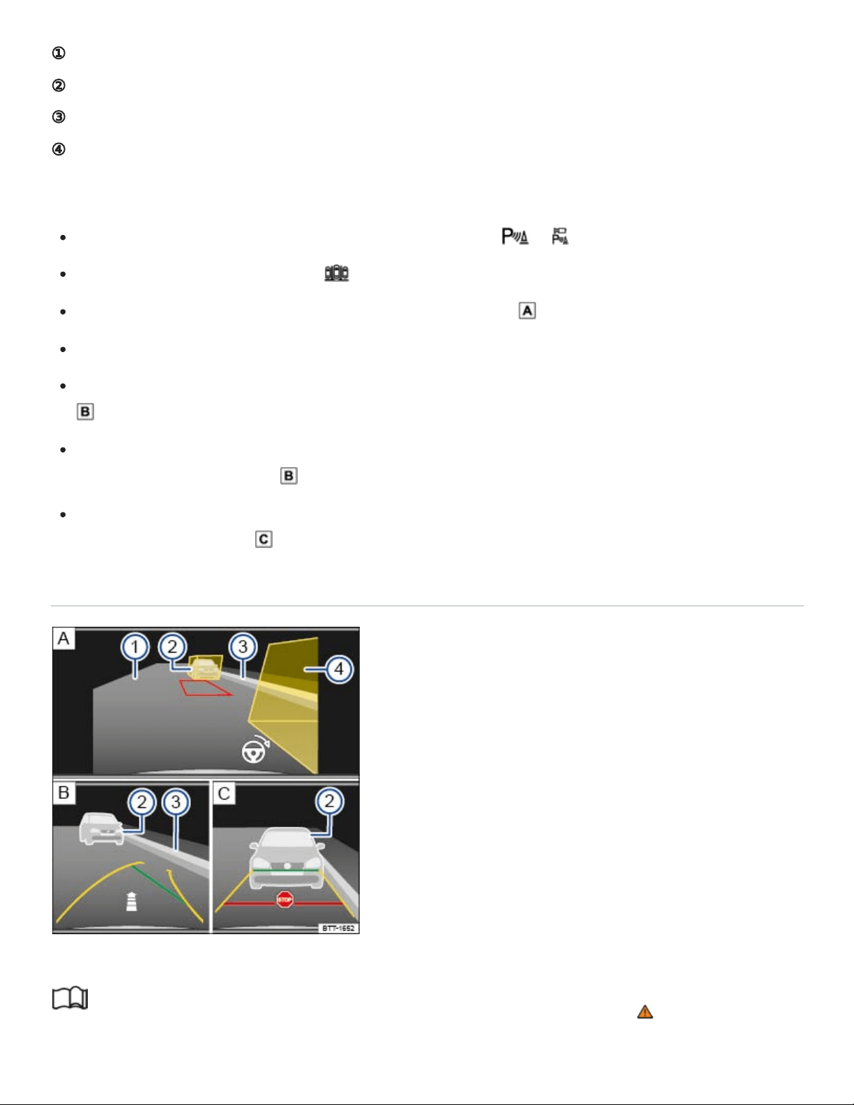
①
②
③
④
Road.
Selected parking space.
Boundary lines for the selected parking space.
Rear boundary of the parking space, such as a curb.
Parking
Before driving past the selected parking space, press the or button.
If necessary, tap the function key in the Infotainment system.
Position the vehicle in front of the parking space ⇒Fig.135 ②.
Heed the following message: Look! Safe to move? !
Slowly back up and steer so that the yellow orientation lines lead into the selected parking space
③.
Align the vehicle in the parking space so that the green and yellow orientation lines are parallel to
the selected parking space ③.
Stop the vehicle before (or at the very latest, when) the horizontal red line reaches the rear bound‐
ary, for example, a curb ④.
Parallel parking
Fig.136Orientation lines for parallel parking (if equipped).
Read and follow the introductory information and safety information first⇒ Introduction to the
subject
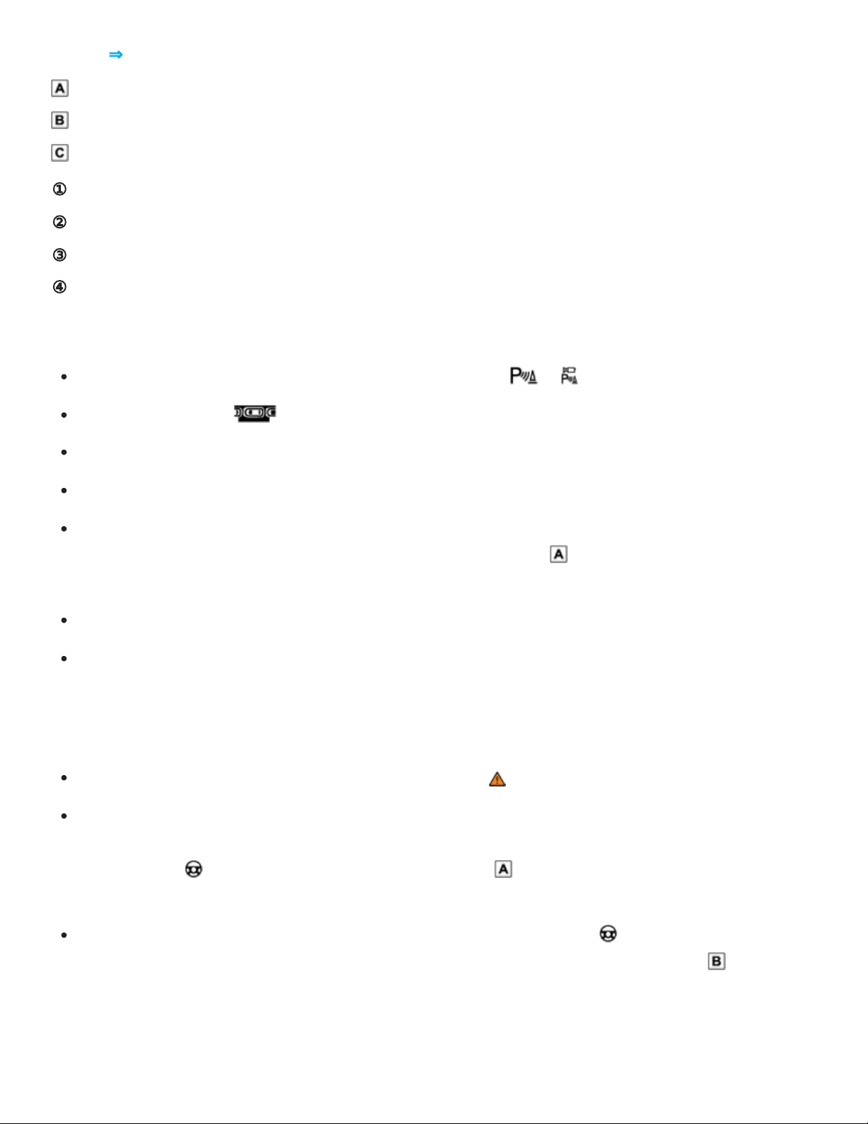
①
②
③
④
Key to ⇒Fig.136 :
Searching for a parking space.
Steering towards a selected parking space.
Maneuvering in the parking space.
Road.
Rear boundary, such as a parked vehicle.
Side boundary of the parking space, such as a curb.
Front boundary, such as a parked vehicle.
Parking
Before driving past the selected parking space, press the or button.
Tap the function key in the Infotainment system.
Switch on the turn signal for the side of the vehicle on which you wish to park.
Slowly drive past the parking space.
Position the vehicle about 3 feet (1 meter) away from and parallel to the parking space. The yel‐
low boxes should completely cover any boundaries ⇒Fig.136 ② and ④. The space between
the boxes must be free of obstacles.
Press the brake pedal and stop the vehicle.
Shift into Reverse (R). Tap the function key MENU in the top left hand corner of the screen to ac‐
cess the full functionality. A red-framed box appears and represents your vehicle's path. If bound‐
aries are outside of the yellow box, then the parking space is too small or your vehicle is not cor‐
rectly positioned. If necessary, find a new parking space or re-position the vehicle.
Heed the following message: Look! Safe to move?⇒ !
Turn the steering wheel until the red box is between the yellow boxes and turns green. You can
use the available parking space marking to position the green box. An arrow over the steering
wheel symbol on the bottom right side of the display shows you which way the steering
wheel should be turned.
Without moving the steering wheel, slowly back up until the stop sign appears OR until the side
green line aligns with the side boundary of the parking space, for example, the curb ③ . An ar‐
row shows the approximate remaining distance, based on the number of segments shown in the
arrow.

Stop the vehicle. Turn the steering wheel in the direction of the arrow above the steering wheel
symbol .
Without moving the steering wheel, slowly back up. The horizontal green line will appear.
Continue to slowly back up until the stop sign appears . OR: At the very latest, stop the vehi‐
cle when the horizontal red line has reached the rear boundary, for example, a parked vehicle ②
.
Tips and troubleshooting
Read and follow the introductory information and safety information first⇒ Introduction to the
subject
If the system is not responding as expected
The camera is dirty ⇒Exterior care and cleaning . The camera may not work properly if blocked
by dirt and snow or residue from abrasive cleaning agents or coatings.
The system requirements are not met ⇒Requirements .
A trailer is electrically connected to the factory-installed trailer hitch.
The camera has been damaged or misaligned in low speed impacts or parking maneuvers.
The system function is impaired by an aftermarket component such as a bicycle rack.
Paint work or structural modifications have been made in the camera area.
If there is no sensor visibility, an error message appears, or the system switches itself off
Clean the camera or remove stickers or accessories from the camera ⇒Exterior care and clean‐
ing .
Check for any visible damage.
Possible solutions
Switch the system off temporarily.
Check whether any of the causes described in this section apply.
After checking all the possible causes and making the necessary adjustments, switch the system
back on.
If the system still does not respond as expected, have it checked by an authorized Volkswagen
dealer or an authorized Volkswagen Service Facility.

NOTE
The camera must be kept clean and free of ice and snow, and must not be covered up by stickers
or other objects, as this will prevent the system from working properly.
Never use abrasive cleaning agents to clean the camera lenses.
Never remove snow or ice on the camera lenses with warm or hot water. This can damage the
camera lenses.
Park Assist
Introduction to the subject
In this chapter you will find information on the following subjects:
⇒Requirements
⇒Selecting a parking space
⇒Parking with Park Assist
⇒Pulling out of a parallel parking space using Park Assist
⇒Tips and troubleshooting
The Park Assist system is an extension of the Park Distance Control system ⇒Park Distance Control
(PDC) and can assist the driver when:
Finding a suitable parking space.
Selecting a parking mode.
Parking in a suitable parallel or perpendicular parking space.
Pulling out of a parallel parking space.
Park Assist steers the vehicle automatically. The driver must control the accelerator, gear changes,
and brake.
The Park Assist system has certain system-related limitations. The driver should exercise caution
when using the Park Assist system ⇒ .

WARNING
Park Assist technology cannot overcome the laws of physics and the limits of the system. Do not
let the extra convenience Park Assist can provide tempt you into taking extra risks. The system is
not a substitute for the driver's full concentration.
Careless or unintentional use of Park Assist may result in accidents and severe injuries.
Always adjust your speed and driving style to road, traffic, weather, and visibility conditions.
Certain surfaces of objects and clothing cannot reflect the signals from the ultrasonic sensors.
The system is unable to detect objects or people wearing these particular types of clothing, or
they may be detected incorrectly.
External sources of sound can affect the signals of the ultrasonic sensors. In certain circum‐
stances, the system may not recognize people or objects.
The ultrasonic sensors have blind spots in which they cannot detect people and objects.
Always be careful and look around you. The sensors have blind spots and cannot always de‐
tect people, animals, or objects in certain situations. Watch out for small children and animals
in particular.
WARNING
Making quick turning movements of the steering wheel when parking or driving out of a parking
space can cause serious injuries.
When parking or driving out of a parking space, do not reach for the steering wheel until
prompted to do so by the system.
NOTE
Park Assist uses parked vehicles, the curb, and other objects for guides. Please ensure that
the wheels and tires are not damaged when parking the vehicle. If necessary, stop the parking
procedure early enough to prevent damage to the vehicle.
Things like trailer draw bars, thin rods, fences, posts, trees, or an open trunk lid may not be
detected by the Park Assist system and could damage the vehicle.
Aftermarket components such as bicycle racks can impair the function of the Park Assist sys‐
tem and may cause vehicle damage.

The sensors in the bumpers can be damaged or become misaligned in low speed impacts and
parking maneuvers. Damaged or misaligned sensors cannot accurately detect or report ob‐
jects that might be within range of the Park Assist system.
When cleaning the sensors with power washers or steam cleaners, only spray the sensors di‐
rectly for a very short time, and always keep the washer nozzle at least 4inches (10cm) from
the sensors.
Noise from rough roads, cobblestones, other vehicles and the surrounding area, for example,
can prevent the Park Assist system from accurately detecting and reporting people and ob‐
jects that may be within range of the sensors.
NOTE
Failure to observe the illuminated text messages can lead to the vehicle being damaged.
Volkswagen recommends practicing with the Park Assist system in a location or parking space
with no traffic in order to become familiar with the system and how it works.
When parking or pulling out of a parking space, the system gives a signal tone to tell the driver to
switch between driving forward and backing up. Do not wait until the Park Distance Control
sounds continuously before changing direction.
If the Park Assist system turns the steering wheel when the vehicle is not moving, the symbol
also appears in the instrument cluster display. Depress the brake pedal so that the steering
movement takes place while the vehicle is not moving, keeping the required number of parking
maneuvers to a minimum.
Certain settings are automatically saved by the driver personalization feature ⇒Driver
Personalization .
A Declaration of Compliance with the United States FCC and Industry Canada regulations is on
⇒Declaration of Compliance, Telecommunications and Electronic Systems .
Requirements
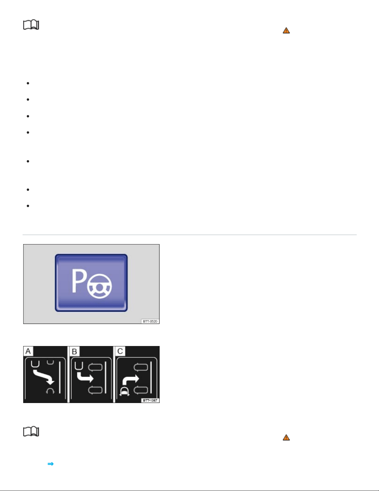
Read and follow the introductory information and safety information first⇒ Introduction to the
subject
To park or to pull out of a parking space, the following requirements must be met:
The ASR must be switched on ⇒Braking assistance systems .
Maintain a distance of 1.6–6.5feet (0.5–2meters) when driving past the parking space.
The parking space must at least be the minimum size required by Park Assist.
For parallel parking: Do not go faster than about 25mph (40km/h) when driving past the parking
space.
For perpendicular parking: Do not go faster than about 12mph (20km/h) when driving past the
parking space.
Do not go faster than about 4mph (7km/h) when parking.
A trailer is electrically connected to the factory-installed trailer hitch.
Selecting a parking space
Fig.137In the lower center console: Button for switching on the Park Assist system.
Fig.138In the instrument cluster display: Parking modes overview.
Read and follow the introductory information and safety information first⇒ Introduction to the
subject
Key to ⇒Fig.138 :

Reverse parallel parking
Reverse perpendicular parking
Forward perpendicular parking
Slowly drive past a row of parked cars, paying attention to traffic.
Press the button ⇒Fig.137 . Park Assist automatically looks for a parking space on the front
passenger side.
Stop when Park Assist shows a recommended parking mode in the instrument cluster display.
Drive into the parking space when the prompt to park appears ⇒Fig.138 ⑤.
If you want Park Assist to look for a parking space on the opposite side of the road, activate the turn
signal for the side of the street on which you want to park.
Switching the parking mode
Other possible parking modes are shown as a mini display.
When the prompt to park appears ⇒Fig.138 ⑤, select a different parking mode by pressing the
button ⇒Fig.137 again. After all relevant parking modes have been displayed, Park Assist switches
off automatically. The originally recommended parking mode is displayed again if you press the
button ⇒Fig.137 another time.
If you wish to drive into a perpendicular parking space instead of backing in, select Forward perpen‐
dicular parking ⇒Fig.138 . Otherwise, the vehicle will back into the perpendicular parking space.
Park Assist can also be switched on after driving past a parking space. If the parking space
meets system requirements, it appears on the display.
Parking with Park Assist
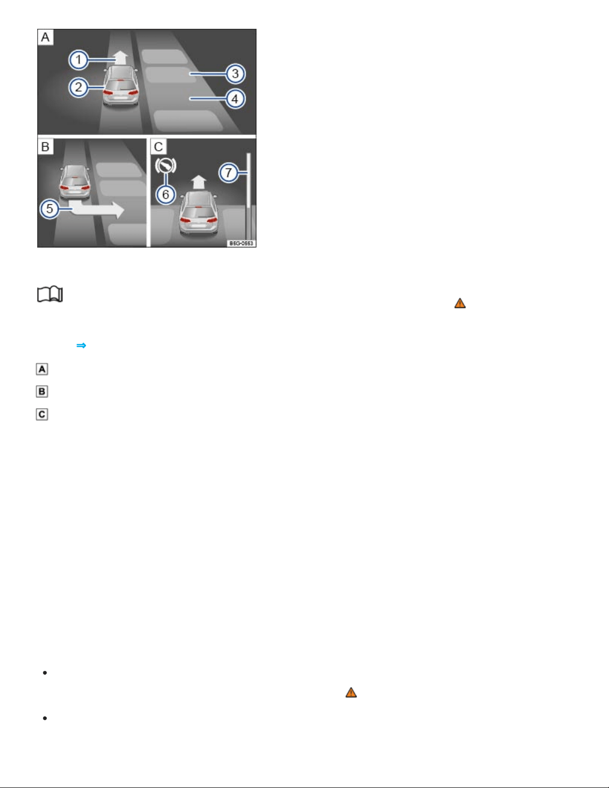
1
2
3
4
5
6
7
Fig.139In the instrument cluster display: Parking perpendicular to the road.
Read and follow the introductory information and safety information first⇒ Introduction to the
subject
Key to ⇒Fig.139 :
Searching for a parking space
Positioning the vehicle for parking
Maneuvering in the parking space
Prompt to drive forward
Your vehicle
Parked vehicles or obstacles
Parking space detected
Arrow indicating the parking suggestion (prompt to park)
Prompt to press the brake pedal
Progress bar: Symbolic display of the relative remaining distance
The requirements for parking using Park Assist must be met and the vehicle must not be moving
⇒Requirements .
Release the steering wheel when the following message is shown in the instrument cluster dis‐
play: Auto. steering active. Check surround. area!⇒ .
Shift into reverse (R) when the prompt to back up appears in the instrument cluster display.
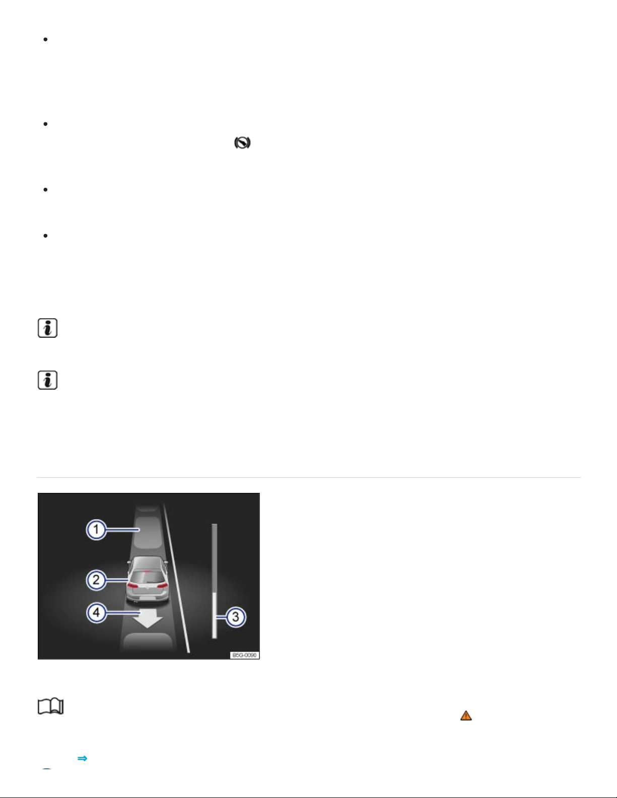
Check the area around the vehicle and carefully depress the accelerator pedal. Do not exceed
4mph (7km/h). The Park Assist system will only turn the steering wheel during the parking pro‐
cedure. The driver must control the accelerator, the brake, and the transmission selector
lever.
Back up the vehicle until there is a continuous tone from the Park Distance Control (PDC) system,
OR until a chime sounds and the symbol along with the prompt to drive forward appear in the
instrument cluster display.
Drive forward until a chime sounds and the prompt to back up is displayed in the instrument
cluster.
Repeat backing up and driving forward until the message Park Assist finished! appears in the
instrument cluster display.
Wait until Park Assist has stopped turning the steering wheel at the end of each parking maneuver for
an optimal parking result.
Stopping the parking maneuver too soon could lead to less than optimal parking results.
If there is not enough room to maneuver the vehicle, the suggested parking space may still be
shown in the instrument cluster display. However, you will not be prompted to park.
Pulling out of a parallel parking space using Park Assist
Fig.140In the instrument cluster display: Driving out of a parallel parking space.
Read and follow the introductory information and safety information first⇒ Introduction to the
subject
Key to ⇒Fig.140 :

Parked vehicles
Your vehicle with reverse gear engaged
Progress bar
Arrow indicating the suggested procedure for driving out of a space
Park Assist can pull out of a parallel parking space if the requirements are met ⇒Requirements .
Press the ⇒Fig.137 button.
Switch the turn signal lever on in the direction (left or right) in which you would like to pull out of
the parking space.
Move the selector lever to Reverse (R).
Release the steering wheel when the following message appears in the instrument cluster display:
Auto. steering active. Check surround. area!⇒ .
Check the area around the vehicle and carefully depress the accelerator pedal. Do not exceed
4mph (7km/h). The Park Assist system will only operate the steering wheel while driving out of
the parking space. The driver controls the accelerator, the brake, and the transmission se‐
lector lever..
Back up the vehicle until there is a continuous tone from the Park Distance Control (PDC) system,
OR until a chime sounds and the symbol along with the prompt to drive forward appears in the
instrument cluster display.
Press the brake pedal until the Park Assist system has stopped steering OR until the symbol
in the instrument cluster display disappears.
Drive forward until a chime sounds and the prompt to back up is displayed in the instrument
cluster.
Repeat backing up and driving forward until a message is displayed in the instrument cluster indi‐
cating when the vehicle can be driven out of the parking space. A chime may also sound.
When traffic permits, pull out of the parking space.
Tips and troubleshooting
Read and follow the introductory information and safety information first⇒ Introduction to the
subject
System fault in the scanned area

The yellow indicator light comes on in the instrument cluster.
If the system is not responding as expected
The sensors are dirty ⇒Exterior care and cleaning . The sensors may not work properly if blocked
by dirt and snow or residue from abrasive cleaning agents or coatings.
The system requirements are not met ⇒Requirements .
The sensors are covered by water.
The cameras have been damaged or misaligned in low speed impacts or parking maneuvers.
A sensor area has been repainted or structural modifications have been made.
The system function is impaired by an aftermarket component such as a bicycle rack.
The sensors may not detect people and objects due to noise interference from rough roads, cob‐
blestones, other vehicles, and the surrounding area.
A wheel has been changed and wheel dimensions are now different.
There is a sharp curve in the road where you wish to park.
If there is no sensor view, an error message appears, or the system switches itself off
Park Assist switches off automatically if a sensor fails.
Clean the sensors or remove stickers or accessories from the sensors ⇒Exterior care and clean‐
ing .
Check for any visible damage.
Possible solutions
Switch the system off temporarily.
Check whether any of the causes described in this section apply.
If wheel dimensions have been changed, new wheel dimensions need to be synchronized with the
system. See your authorized Volkswagen dealer or authorized Volkswagen Service Facility for
assistance.
After checking all the possible causes and making the necessary adjustments, switch the system
back on.
If the system still does not respond as expected, have it checked by an authorized Volkswagen
dealer or an authorized Volkswagen Service Facility.

Interrupting or automatically stopping a parking procedure or driving out of a parking space
The Park Assist system cancels the parking procedure or movement out of a parking space if one of
the following occurs:
The button is pressed.
The vehicle speed is faster than about 4mph (7km/h).
The driver intervenes by using the steering wheel.
The driver door is opened.
The parking procedure was not completed within about 6minutes after switching on the feature.
There is a system fault (system is temporarily unavailable).
ASR is switched off.
Regulation related to driving dynamics takes place through ASR or ESC.
If none of the above situations apply, resume Park Assist by pressing the button again.
Park Assist attempts to steer when the vehicle is not moving
If Park Assist tries to turn the steering wheel when the vehicle is not moving, the white symbol ap‐
pears in the instrument cluster display.
Depress the brake pedal.
Park Assist automatic braking
Park Assist can help the driver by braking automatically in certain situations. The driver is always re‐
sponsible for braking in time. Depending on certain conditions such as weather, vehicle condition, ve‐
hicle load, or vehicle angle, the Park Assist system can bring the vehicle to a stop before it reaches
an obstacle. Depress the brake pedal ! An automatic brake intervention stops the current parking
maneuver.
Rear Traffic Alert
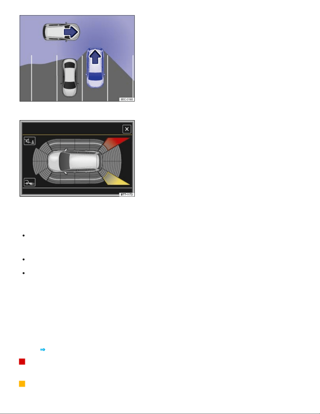
Fig.141Rear Traffic Alert: Monitored area around the vehicle that is backing out of a parking space.
Fig.142Rear Traffic Alert display (may vary depending on vehicle equipment).
Switching the Rear Traffic Alert on and off
You can turn Rear Traffic Alert on or off in the Vehicle settings menu in the Infotainment system
⇒Infotainment system operation and displays .
OR: In the Assist systems menu in the instrument cluster display ⇒Instrument cluster menus .
OR: Press the driver assistance systems button on the multi-function steering wheel to open the
Assist systems menu ⇒Driver Assistance systems button .
Function
The Rear Traffic Alert system uses the radar sensors in the rear bumper to monitor the traffic crossing
behind your vehicle when you are backing out of a parking space or maneuvering, for example, in
traffic situations with poor visibility.
Key to ⇒Fig.142 :
Stop backing up! The red area indicates that the system has detected traffic behind the
vehicle.
The yellow area indicates that the system has possibly detected traffic behind the vehicle.

A warning sounds if the system detects approaching traffic behind your vehicle when backing up
⇒Fig.142 (red area).
Vehicles without Park Distance Control (PDC): There is a warning tone and a text message in the
instrument cluster display.
Vehicles with Park Distance Control (PDC): There is a continuous warning tone from the PDC. If
PDC is switched off, a warning for the driver may not be possible, and therefore the Rear Traffic
Alert is also switched off.
If there is a system malfunction in the scanned area, a yellow indicator light appears.
Automatic braking
If Rear Traffic Alert detects an approaching vehicle and the driver does not press the brake pedal, the
system can intervene with automatic braking.
Rear Traffic Alert assists the driver with harsh automatic braking that could help prevent or reduce
damage that can result from a collision. Automatic braking occurs while backing up at speeds be‐
tween 1–7mph (1–12km/h). Once the system detects that your vehicle is not moving, it keeps the
vehicle from moving for up to 2seconds.
After automatic braking, about 10seconds must pass before the system can brake automatically
again.
The driver can interrupt the automatic braking and take control of the vehicle by pressing firmly on the
accelerator or brake pedal.
Automatic deactivation of Rear Traffic Alert
The radar sensors for Rear Traffic Alert deactivates automatically if the system detects an obstruction
over a radar sensor. This could occur if the radar sensor area is covered by ice or snow, for example.
The Rear Traffic Alert deactivates automatically and cannot be reactivated when a trailer is electrically
connected to the trailer hitch. A text message appears in the instrument cluster when a trailer is elec‐
trically connected and the driver starts to drive. Once the trailer has been disconnected, Rear Traffic
Alert is automatically reactivated.
WARNING
The Rear Traffic Alert technology cannot overcome the laws of physics and limits of the system.
Careless or unintentional use of Rear Traffic Alert may result in accidents and serious injuries.

The Rear Traffic Alert is not a substitute for careful and attentive driving.
Never use the system when visibility is limited or in complex traffic situations, for example, on
heavily traveled roads or when there are multiple lanes.
Always watch for people, especially small children, bicycles, animals, and objects, because
the Rear Traffic Alert may not always be able to detect them. Rear Traffic Alert cannot detect
people, animals, and things that are moving slowly or not at all.
The Rear Traffic Alert does not always brake the vehicle to a complete stop.
The harsh automatic braking will be uncomfortable for many people, and if you or your pas‐
sengers have special conditions or sensitivities, particularly in the neck, you may want to
switch off Rear Traffic Alert.
NOTE
The radar sensors in the rear bumper can be damaged or become misaligned in low-speed
impacts and parking maneuvers. The system can switch itself off or may be impaired as a
result.
Always keep the rear bumper clean and free of snow and ice so that the radar sensors can
work properly. Do not cover the radar sensor area.
The rear bumper may only be painted with vehicle paint that is approved by Volkswagen.
Other paints may make the Rear Traffic Alert system work improperly or cause it to
malfunction.
A Declaration of Compliance with the United States FCC and Industry Canada regulations is on
⇒Declaration of Compliance, Telecommunications and Electronic Systems .
You must switch off Rear Traffic Alert manually when towing a trailer if the system does not deac‐
tivate automatically.
Area View
Introduction to the subject
In this chapter you will find information on the following subjects:

⇒Requirements
⇒Switching Area View on and off
⇒Display and camera views
⇒Tips and troubleshooting
There are cameras in the radiator grille, the outside mirrors, and the trunk lid to assist the driver while
parking, maneuvering, or driving off-road. The camera images are displayed in the Infotainment
system.
The functions and displays of the Rear View Camera system may vary.
Objects or another vehicle may seem closer or farther away on the screen than they really are, for ex‐
ample, when driving onto a slope or when approaching protruding objects.
WARNING
Using the cameras to estimate the distance to people and things around the vehicle can result in
collisions and severe personal injury.
The camera lenses can enlarge and distort the field of vision and can cause objects on the
screen to appear altered and imprecise.
Due to the screen resolution or in low-light conditions, the cameras may not pick up thin posts,
chain-link fences and similar fences, and other objects, or it may not show them clearly.
The cameras have blind spots in which they cannot show people and objects.
Always be careful and look around you when maneuvering. The Area View system cannot
show people, animals, and objects in certain situations. Watch out for small children and ani‐
mals in particular.
Always keep the camera lenses clean and free of snow and ice; do not cover the lenses.
WARNING
Area View technology cannot overcome the laws of physics and the limits of the system.
Careless or unintentional use of Area View may result in accidents and severe injuries.
Always adjust your speed and driving style to road, traffic, weather, and visibility conditions.

Never pay so much attention to the images on the screen that you fail to notice what is going
on around you.
Always watch for people, especially small children, animals, and objects, because the cam‐
eras may not always be able to show them.
The system may not be able to clearly show everything behind the vehicle.
NOTE
The Area View cameras show only two-dimensional images on the screen. Due to the lack of
depth of field, it may be difficult or impossible to identify protruding objects or depressions in
the road, for example.
Things like thin rods, fences, posts, and trees may not be shown by the camera and could
damage the vehicle.
NOTE
Smaller objects up to about 20 inches (50 cm) around the vehicle will not be shown by the cam‐
eras and could cause vehicle damage.
Volkswagen recommends practicing using the Area View system in a safe place with no traffic or
in a parking lot in order to familiarize yourself with the system and the way it works.
Requirements
Read and follow the introductory information and safety information first⇒ Introduction to the
subject
The following requirements for parking while using Area View must be met:
The doors and trunk lid must be closed.
There must be a clear and complete view of the area around the vehicle.
The parking or maneuvering area must be level.
The vehicle speed must not be more than about 10 mph (15 km/h).
The rear of the vehicle must not be heavily loaded.
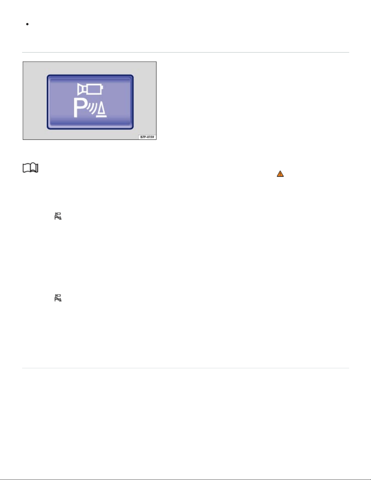
The driver must be familiar with the system.
Switching Area View on and off
Fig.143In the lower center console: Button to switch on Area View.
Read and follow the introductory information and safety information first⇒ Introduction to the
subject
Switching Area View on
Press the button ⇒Fig.143 . The display will not switch on at speeds above about 10mph
(15km/h).
OR: Shift into reverse (R). Move your hand toward the screen and tap the function key MENU in the
top left hand corner of the screen to access the full Area View functionality.
Switching Area View off
Press the button ⇒Fig.143 again.
OR: Move your hand toward the screen and press the x function key.
OR: Drive forward faster than about 10mph (15km/h).
Display and camera views
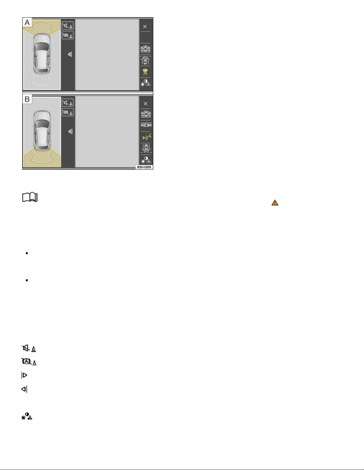
x
Fig.144Display of Area View: Front camera, Rear camera.
Read and follow the introductory information and safety information first⇒ Introduction to the
subject
The functions and displays of the Area View system may vary depending on equipment.
Left screen: Mini bird's-eye view. Tap one of the four areas around the vehicle or the vehicle itself
to change the view in the right screen.
Right screen: The individual camera images are displayed corresponding to the area selected in
the left screen.
The following function keys appear when you move your hand toward the screen or tap the MENU
function key.
Screen display
Switch the PDC sound on or off.
Switch maneuver braking on and off.
Show the mini bird's-eye view display.
Hide the mini bird's-eye view display.
Close the current display.
Adjust the display brightness, contrast, and color.

The available menu options and possible camera views (referred to as modes) for the corresponding
camera are shown on the right-hand side of the screen. The view (mode) that is currently active is
marked.
Modes and camera views
Shows cross-traffic in front of the vehicle.
Shows the area in front of the vehicle. Orientation lines are displayed to help assist with for‐
ward perpendicular parking.
Shows the area behind the vehicle. Orientation lines are displayed to help assist with reverse
perpendicular parking. See ⇒Perpendicular parking .
Shows the area directly in front of the vehicle in a bird's-eye view.
Shows both areas next to the vehicle simultaneously.
Shows the area on the driver side of the vehicle.
Shows the area on the front passenger side of the vehicle.
Shows the area directly behind the vehicle. Colored orientation boxes and lines are displayed
to help assist with parallel parking. See ⇒Parallel parking .
Shows the area behindt he vehicle including the vehicle bumper.
Shows cross-traffic behind the vehicle ⇒ Cross-traffic .
Bird's eye views (if equipped)
Bird's-eye view of the vehicle and surrounding area. Depending on equipment, the Park
Distance Control vehicle path display may also be shown.
Bird's-eye view of the vehicle and surrounding area.
Vehicle and surrounding area are shown at an angle from above.
Vehicle and surrounding area are shown from the side.
The orientation lines are displayed independent of the area around the vehicle. There is no auto‐
matic detection of obstacles. The driver is responsible for judging if the vehicle fits into the park‐
ing spot.
Area View hides all orientation lines and assistance areas when the factory-installed trailer hitch
is electrically connected to a trailer.
Tips and troubleshooting

Read and follow the introductory information and safety information first⇒ Introduction to the
subject
If there is no sensor visibility, an error message appears, or the system switches itself off
Clean the cameras or remove stickers or accessories from the cameras ⇒Exterior care and
cleaning .
Check for any visible damage.
The system does not respond as expected
The cameras are dirty ⇒Exterior care and cleaning . The cameras may not work properly if
blocked by dirt and snow or residue from abrasive cleaning agents or coatings.
The system requirements are not met ⇒Requirements .
The cameras have been damaged or misaligned in low speed impacts or parking maneuvers.
The system function is impaired by an aftermarket component such as a bicycle rack.
Paint work or structural modifications have been made in the camera areas.
Possible solutions
Switch the system off temporarily.
Check whether any of the causes described in this section apply.
After checking all the possible causes and making the necessary adjustments, switch the system
back on.
If the system still does not respond as expected, have it checked by an authorized Volkswagen
dealer or an authorized Volkswagen Service Facility.
NOTE
The cameras must be kept clean and free of ice and snow, and must not be covered up by stick‐
ers or other objects, as this will prevent the system from working properly.
Never use abrasive cleaning agents to clean the camera lenses.
Never remove snow or ice on the camera lenses with warm or hot water. This can damage the
camera lenses.
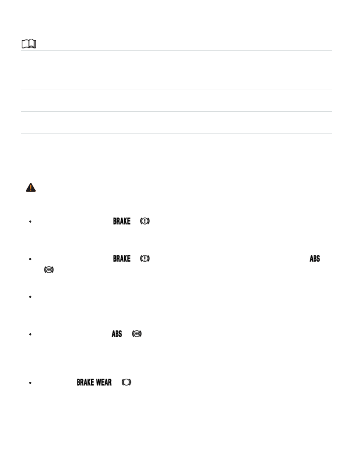
Braking assistance systems
Introduction to the subject
In this chapter you will find information on the following subjects:
⇒Braking assistance systems
⇒Switching Anti-Slip Regulation (ASR) and ESC Sport mode on and off
⇒Tips and troubleshooting
The braking assistance systems are the Anti-Lock Brake System (ABS), Brake Assist System
(BAS), Electronic Differential Lock (EDL), Anti-Slip Regulation (ASR), and Electronic Stability Control
(ESC).
WARNING
Driving with bad brakes can cause a collision and serious personal injury.
If the brake warning light or does not go out, or lights up when driving, either the
brake fluid level in the reservoir is too low or there is a fault in the brake system. Stop the vehi‐
cle as soon as you can do so safely and get expert assistance ⇒Brake fluid .
If the brake warning light or lights up at the same time as the ABS warning light
or , the ABS may not be working properly. This could cause the rear wheels to lock up rela‐
tively quickly during braking. Rear wheel brake lock-up can cause loss of vehicle control.
If you believe the vehicle is safe to drive, drive slowly and very carefully to the nearest autho‐
rized Volkswagen dealer, authorized Volkswagen Service Facility, or other qualified workshop
and have the brake system inspected. Avoid sudden hard braking and steering.
If the ABS indicator light or does not go out, or if it lights up while driving, the ABS sys‐
tem is not working properly. The vehicle can then be stopped only with the standard brakes
(without ABS). You will not have the protection ABS provides. Contact your authorized
Volkswagen dealer or an authorized Volkswagen Service Facility as soon as possible.
If the symbol or lights up in the instrument cluster display, whether alone or to‐
gether with a text message, immediately contact an authorized Volkswagen dealer or autho‐
rized Volkswagen Service Facility to have the brake pads checked and, if necessary, replaced.
Braking assistance systems

Read and follow the introductory information and safety information first⇒ Introduction to the
subject
The ESC, ABS, BAS, ASR, and EDL braking assistance systems work only when the engine is run‐
ning. These systems can significantly improve active driving safety.
The driver is responsible for driving safely ⇒ .
Electronic Stability Control (ESC)
ESC helps to improve road holding and vehicle dynamics to help reduce the probability of skidding
and loss of vehicle control. It works only when the engine is running. ESC detects certain difficult driv‐
ing situations, including when the vehicle is beginning to spin (yaw) out of control. ESC then helps
you to get the vehicle back under control by selectively braking the wheels and/or reducing engine
power and by providing steering assistance to help hold the vehicle on the driver's intended course.
ESC has limitations. It is important to remember that ESC cannot overcome the laws of physics. It will
not always be able to help out under all conditions you may come up against. For example, ESC may
not always be able to help you master situations where there is a sudden change in the coefficient of
friction of the road surface. When there is a section of dry road that is suddenly covered with water,
slush or snow, ESC cannot perform the same way it would on a dry surface. If the vehicle hy‐
droplanes (rides on a cushion of water instead of the road surface), ESC will not be able to help you
steer the vehicle because contact with the pavement has been interrupted and the vehicle cannot be
braked or steered. During fast cornering, particularly on winding roads, ESC cannot always deal as
effectively with difficult driving situations as it can at lower speeds. When towing a trailer, ESC is not
able to help you regain control as it would if you were not towing a trailer.
Always adjust your speed and driving style to visibility, road, traffic, and weather conditions. ESC can‐
not override the vehicle's physical limits, increase the available traction, or keep a vehicle on the road
if road departure is a result of driver inattention. Instead, ESC improves the possibility of keeping the
vehicle under control and on the road during extreme maneuvers by using the driver's steering inputs
to help keep the vehicle going in the intended direction. If you are traveling at a speed that causes
you to run off the road before ESC can provide any assistance, you may not experience the benefits
of ESC.
ESC includes and/or works together with the ABS, BAS, ASR, EDL, and XDL systems (see below).
ESC is switched on all the time.

In certain situations when you need less traction or additional traction cannot be achieved, you can
switch off Anti-Slip Regulation (ASR) and ESC Sport mode (if equipped) in the Infotainment system
⇒Switching Anti-Slip Regulation (ASR) and ESC Sport mode on and off .
Be sure to switch ASR on again when you no longer need less traction.
Anti-Slip Regulation (ASR)
ASR reduces engine power directed to spinning wheels and adjusts power to the road conditions.
Even under poor road conditions, ASR can make it easier to get moving, accelerate, and climb hills.
ASR can be switched on and off manually ⇒Switching Anti-Slip Regulation (ASR) and ESC Sport
mode on and off .
Anti-Lock Brake System (ABS)
ABS helps to keep the wheels from locking up and helps to maintain the driver's ability to steer and
control the vehicle. This means the vehicle is less likely to skid, even during hard braking:
Push the brake pedal down hard and hold it there. Don't take your foot off the pedal or reduce the
force on the pedal!
Do not pump the brake pedal or let up on it!
Steer the vehicle while pushing down hard on the brake pedal.
ABS stops working if you release or let up on the brake.
When ABS is doing its job, you will notice a slight vibration through the brake pedal and hear a
noise. ABS cannot shorten the stopping distance under all conditions. The stopping distance may
even be longer, for instance, when driving on gravel or on newly fallen snow covering an icy or slip‐
pery surface.
When driving forward on loose surfaces, a special off-road ABS is automatically switched on. In this
mode, the front wheels could lock briefly. This shortens the braking distance in off-road situations as
the wheels dig into loose surfaces. This occurs only when driving straight ahead. When the front
wheels are turned, the normal ABS is switched on.
Brake Assist (BAS)
The Brake Assist System can help to reduce stopping distances. If you press the brake pedal very
quickly, BAS detects an emergency situation. It then very quickly builds up full brake system pres‐
sure, maximizing braking power and reducing the stopping distance. This way, ABS can be switched

on more quickly and efficiently.
Do not reduce pressure on the brake pedal! BAS switches off automatically as soon as you release
or let up on the brake.
Electronic Differential Lock (EDL and XDL)
EDL is applied during regular straight-line acceleration. EDL gently brakes a drive wheel that has lost
traction (spinning) and redirects the drive force to other drive wheels. In extreme cases, EDL automat‐
ically switches off to keep the brake from overheating. As soon as the brake has cooled down, EDL
automatically switches on again.
XDL is an extension of the Electronic Differential Lock system. XDL detects slippage of the inside
front wheel during fast cornering. XDL applies enough brake pressure to this wheel in order to stop
the slippage. This improves traction, which helps the vehicle stay on track.
Automatic Post-Collision Braking System
In an accident, the Automatic Post-Collision Braking System can help the driver to reduce the risk of
skidding and the danger of secondary collisions through automatic braking.
The Automatic Post-Collision Braking System only works if the airbag control unit registers the corre‐
sponding triggering threshold during the accident, and the accident occurs at a speed greater than
6mph (10km/h).
The ESC brakes the vehicle automatically, provided that the hydraulic braking system, the ESC, and
the electrical system are undamaged and stay functional.
The following actions override automatic braking in the event of an accident:
When the driver depresses the accelerator.
When the brake pressure transmitted through the depressed brake pedal is greater than the brake
pressure provided by the system.
WARNING
Driving fast on icy, slippery, or wet roads can lead to a loss of control and result in serious per‐
sonal injury for you and your passengers.
Always adjust your speed and driving style to road, traffic, weather, and visibility conditions.
Never let the additional safety that ESC, ABS, BAS, ASR, and EDL can provide tempt you into

taking extra risks.
Braking assistance systems cannot overcome the laws of physics and always prevent loss of
vehicle control. Slippery and wet roads are still dangerous even with ESC and the other
systems!
Driving too fast on wet roads can cause the wheels to lose contact with the road and hy‐
droplane. A vehicle that has lost road contact cannot be braked, steered, or controlled.
These systems cannot reduce the risk of accident, for example if you drive too fast for condi‐
tions or if you do not keep your distance from the vehicle in front of you.
Although these systems are very effective and can help you control the vehicle in many difficult
situations, always remember that your vehicle handling control is limited by tire traction.
When accelerating on a slippery surface, for example on ice and snow, depress the accelera‐
tor carefully. Even with these systems, the wheels may start to spin, leading to a loss of vehi‐
cle control.
WARNING
The effectiveness of ESC can be significantly reduced if other components and systems that af‐
fect vehicle dynamics, including but not limited to brakes, tires, and other systems mentioned
above, are not properly maintained or functioning.
Always remember that vehicle alterations or modifications can affect the functioning of the
ABS, BAS, ASR, EDL, and ESC systems.
Changing the vehicle suspension or using an unapproved tire/wheel combination can change
the way the ABS, BAS, ASR, EDL, and ESC systems work and reduce their effectiveness.
The effectiveness of ESC is also determined by the tires installed ⇒Tires and wheels .
WARNING
Driving without braking assistance systems can greatly lengthen the distance necessary to com‐
pletely stop the vehicle, which can lead to a loss of control and result in serious personal injury
for you and your passengers.
Never let the vehicle coast when the engine is switched off.
When the braking assistance systems are not working or when the vehicle is being towed, the
brake must be depressed harder because the braking distance is greater.

If ABS is not working, ESC, ASR, and EDL will also not work.
Switching Anti-Slip Regulation (ASR) and ESC Sport mode on and off
Read and follow the introductory information and safety information first⇒ Introduction to the
subject
Your vehicle may be equipped with ESC sport mode. ASR is switched off and the brake intervention
functions of ESC are limited when ESC Sport is switched on.
Switch off ASR only in situations where there is not enough traction, such as the following:
When driving in deep snow or on loose surfaces.
When rocking the vehicle back and forth when you are stuck.
Afterward, activate ASR again or deactivate ESR sport mode
Switching ASR or ESC sport mode off and on
You can switch ASR or ESC Sport off and on Vehicle settings menu in the Infotainment system
⇒Infotainment system operation and displays .
When ASR is switched off or ESC sport mode is switched on, a driver information message appears
in the instrument cluster display and the indicator light in the instrument cluster lights up ⇒Tips and
troubleshooting .
Depending on vehicle equipment, additional text messages may appear in the instrument cluster
display to provide further information or to ask you to perform certain tasks ⇒Using the instru‐
ment cluster menus .
Tips and troubleshooting
Read and follow the introductory information and safety information first⇒ Introduction to the
subject
When the ignition is switched on, several warning and indicator lights come on briefly for a function
check. They go out after a few seconds.

OR ABS failure or malfunction
The yellow indicator light comes on.
See an authorized Volkswagen dealer or an authorized Volkswagen Service Facility.
The vehicle brakes will work without ABS.
OR ABS is operating to help prevent the wheels from locking up
The yellow indicator light flashes.
ASR or ESC is operating
The yellow indicator light flashes.
ESC switched off by the system
The yellow indicator light comes on.
Switch the ignition off and on again.
If necessary, drive a short distance at a speed of 10–12mph (15–20km/h).
If the indicator light stays on, see an authorized Volkswagen dealer or an authorized Volkswagen
Service Facility.
ASR manually deactivated or ESC Sport mode manually activated
The yellow indicator light comes on.
If the braking assistance systems make noises
You may hear noises when these systems are active. This is normal and no cause for concern.
If there is an unexpected reduction in engine power
All 4wheels must be equipped with identical tires in order for ESC and ASR to work properly.
Differences in the tread circumference of the tires can cause the system to reduce the engine power
when it is not expected.
WARNING
Failure to heed warning lights and instrument cluster text messages can result in a collision and
serious personal injury.
Never ignore warning lights or text WARNINGS.
Always stop the vehicle as soon as it is safe to do so.
Whenever stalled or stopped for repair, move the vehicle a safe distance off the road, stop the
engine, turn on the emergency flashers, and use other warning devices to warn approaching
traffic.
Never park the vehicle in areas where the hot catalytic converter and exhaust system could
come into contact with dry grass, brush, spilled fuel, oil, or other material that can catch fire.
A broken-down vehicle presents a high accident risk for itself and others. Switch on emer‐
gency flashers and set up a warning triangle to warn oncoming traffic.
WARNING
If the brake warning light or lights up at the same time as the ABS warning light
or , the ABS may not be working properly. This could cause the rear wheels to lock up rela‐
tively quickly during braking. Rear wheel brake lock-up can cause loss of vehicle control.
If the ABS indicator light or does not go out, or if it lights up while driving, the ABS sys‐
tem is not working properly. The vehicle can then be stopped only with the standard brakes
(without ABS). You will not have the protection ABS provides. Contact your authorized
Volkswagen dealer or an authorized Volkswagen Service Facility as soon as possible.
Storage and equipment
Storage areas
Introduction to the subject
In this chapter you will find information on the following subjects:
⇒Storage compartment on the driver side
⇒Glove compartment
⇒Storage compartment in the front center console
⇒Storage compartment between the front seats
⇒Eyeglass storage compartment in the overhead console

⇒Other storage compartments
Store only lightweight or small objects in storage compartments.
WARNING
Loose objects can be thrown around the inside of the vehicle when the vehicle is moving, espe‐
cially during sudden maneuvers and hard braking. This can cause serious personal injuries and
even make the driver lose control of the vehicle.
Never let animals ride in the vehicle's open storage compartments, on top of the instrument
panel, or on the luggage compartment cover behind the rear seat backrests.
Never put hard, heavy or sharp objects in these places or in articles of clothing or bags in the
passenger compartment.
Always keep storage compartments closed while driving.
WARNING
Objects in the driver footwell can prevent the pedals from moving freely. This can cause loss of
vehicle control and increase the risk of serious personal injuries.
Always make sure that nothing can interfere with the pedals.
Always fasten floor mats securely to the floor.
Never put floor mats or other floor coverings on top of already installed floor mats.
Always make sure that nothing can fall into the driver footwell while the vehicle is moving.
WARNING
Some kinds of cigarette lighters can be lit unintentionally, or crushed causing a fire that can result
in serious burns and vehicle damage.
Always make sure that there are no lighters in the seat tracks or near other moving parts be‐
fore adjusting the seats.
Before closing a storage compartment, always make sure that no cigarette lighter can be acti‐
vated, crushed, or otherwise damaged.
Never leave a cigarette lighter in a storage compartment, on the instrument panel, or in other
places in the vehicle. Heat buildup in the passenger and luggage compartment of a parked ve‐
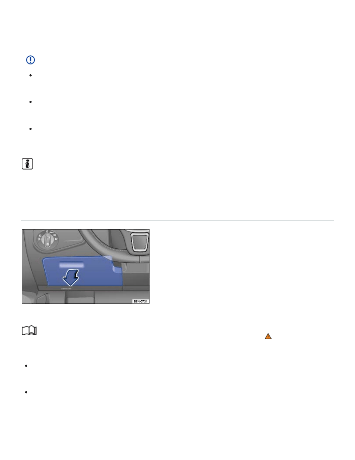
hicle can result in temperatures in the vehicle that are much higher than the outside tempera‐
tures, particularly in summer. High temperatures could cause the cigarette lighter to catch fire.
NOTE
The defroster heating wires or antenna in the rear window can be damaged by hard or sharp
things on the shelf below the rear window.
Do not keep any food, medicine, or other items sensitive to heat or cold in the vehicle. They
can be damaged or made unusable by heat or cold.
Things that are made of transparent materials (such as eyeglasses, magnifying glasses, or
transparent suction cups on the windows) can magnify sunlight and damage the vehicle.
The ventilation slots in the luggage compartment must not be blocked so that stale air can es‐
cape from the vehicle.
Storage compartment on the driver side
Fig.145On the driver side: Storage compartment.
Read and follow the introductory information and safety information first⇒ Introduction to the
subject
To open: Push the release lever up and then pull the handle ⇒Fig.145 in the direction of the
arrow.
To close: Push the lid up until it latches.
Glove compartment
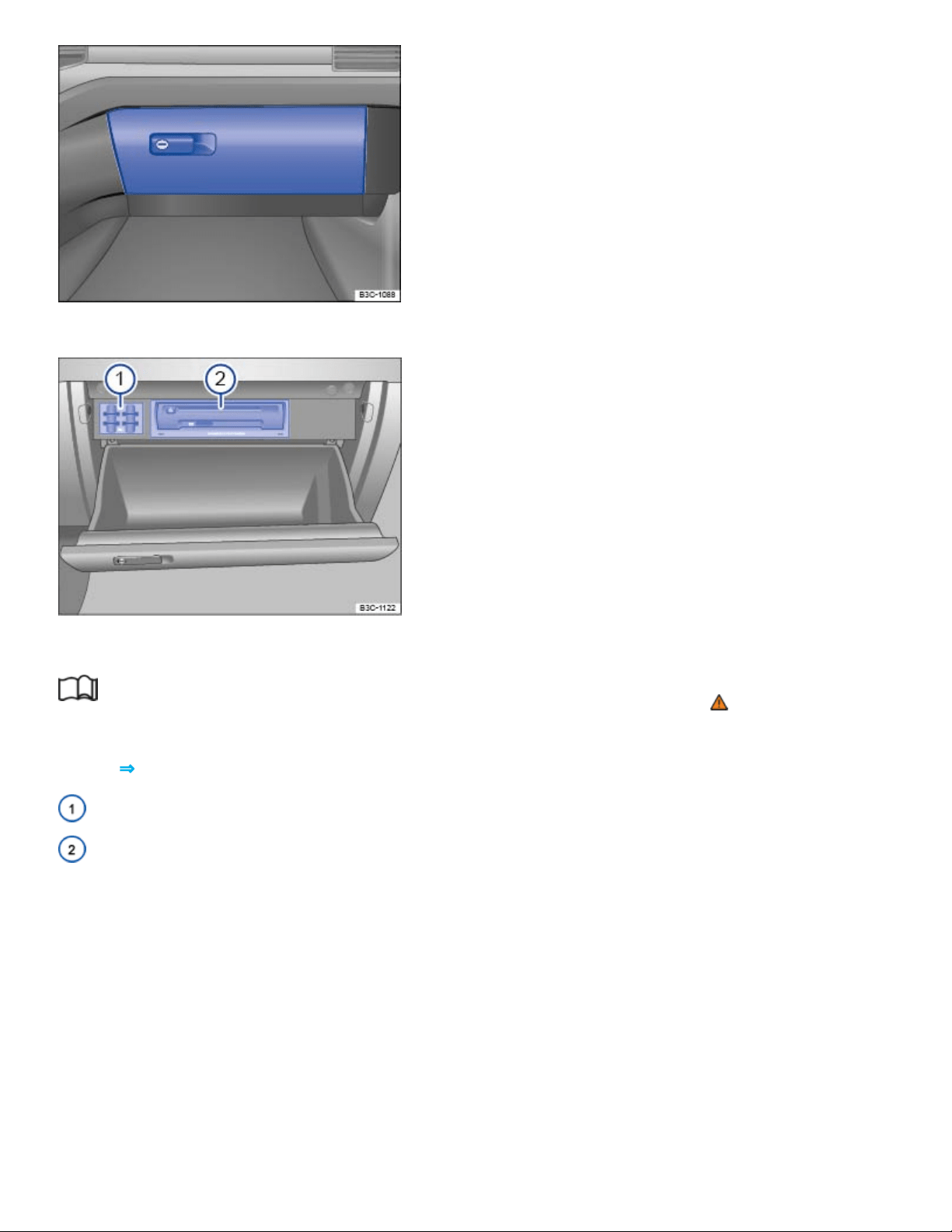
Fig.146On the passenger side: Glove compartment.
Fig.147Inside the glove compartment.
Read and follow the introductory information and safety information first⇒ Introduction to the
subject
Key to ⇒Fig.147 :
SD card holders
Infotainment system accessories and card reader (if equipped) ,ChapterInfotainment System
Opening and closing the glove compartment
To open, pull the handle ⇒Fig.146 .
To close, push the lid up.
Owner's Manual
The Owner's Manual can be stored in the glove compartment.
Storage net
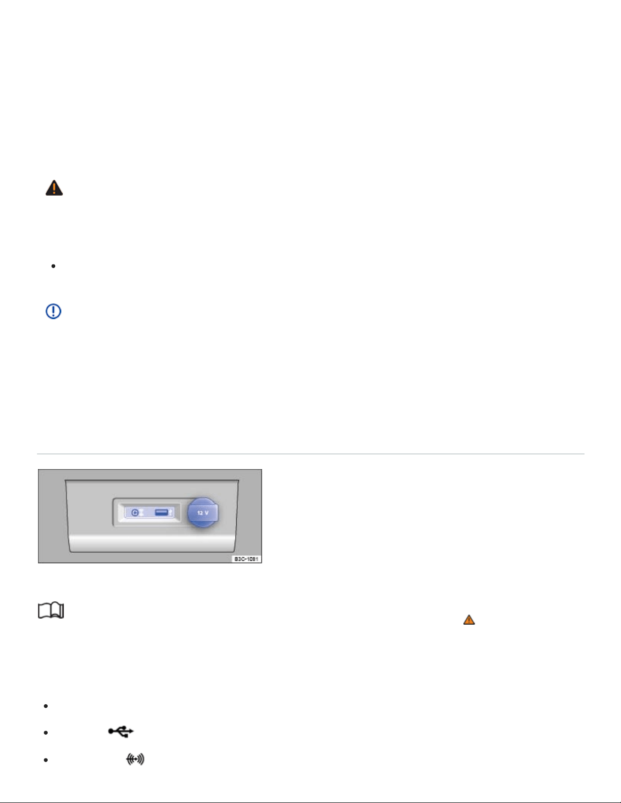
Depending on equipment, there may be a storage net on the side of the center console.
Infotainment system accessories
Vehicles equipped with an Infotainment system may have a CD player, SD card readers, or other
Infotainment System accessories ⇒Fig.147② in the glove compartment. See ,ChapterInfotainment
System for further information.
WARNING
An open glove compartment door can increase the risk of serious injury during sudden braking or
driving maneuvers or in a crash.
Always keep the glove compartment closed while the vehicle is moving.
NOTE
In some vehicle models, design considerations have made it necessary to have openings in the
glove compartment behind the Owner's Manual slot, for example. Small items may fall through
these openings and get behind the instrument panel. This can cause unusual noises and damage
the vehicle. Never put any small objects in the glove compartment for this reason.
Storage compartment in the front center console
Fig.148In the front center console.
Read and follow the introductory information and safety information first⇒ Introduction to the
subject
The storage compartment in the front center console ⇒Fig.7⑤ may have the following:
12 Volt socket
USB port ⇒BookletInfotainment System,
AUX-IN jack ⇒BookletInfotainment System,
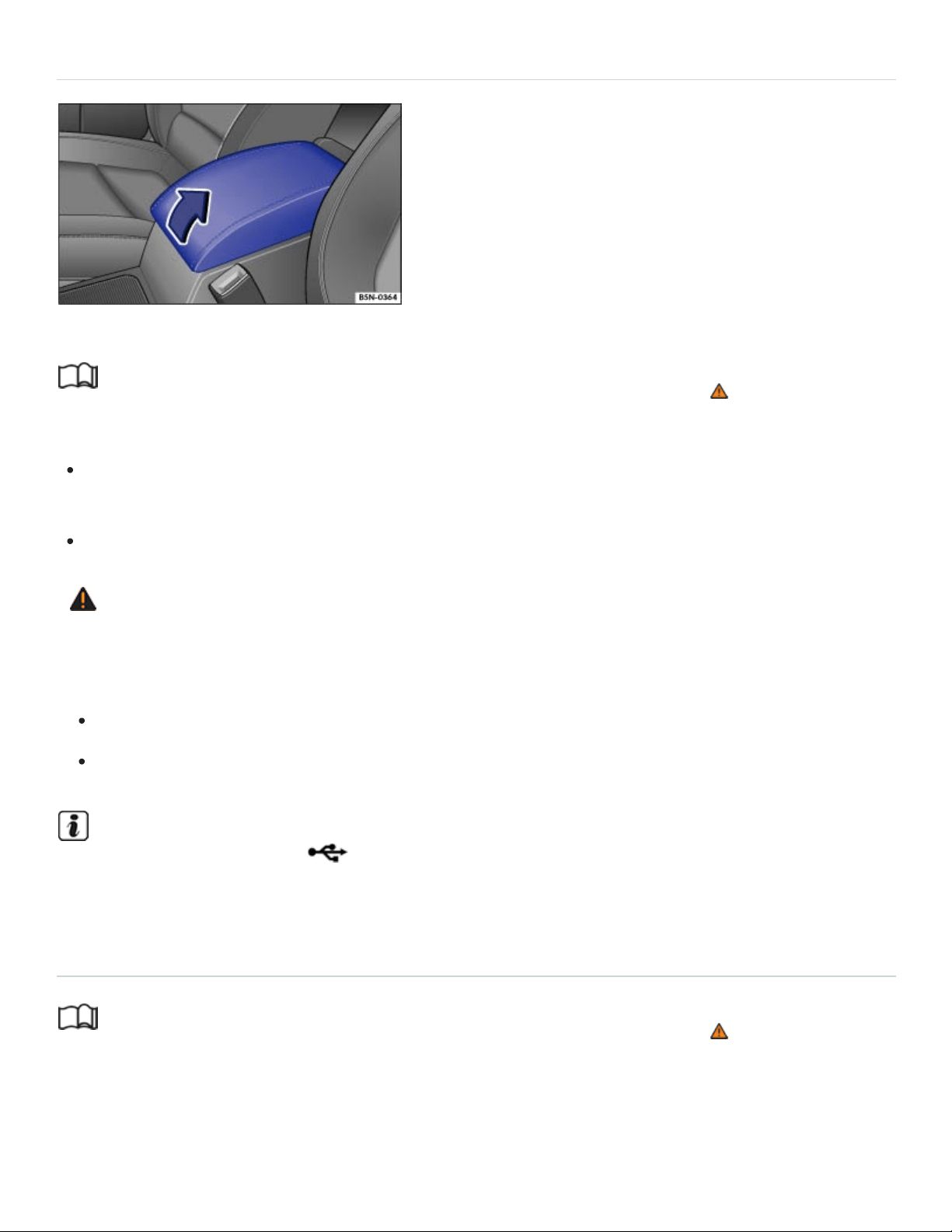
Storage compartment between the front seats
Fig.149In the front center armrest: Storage compartment.
Read and follow the introductory information and safety information first⇒ Introduction to the
subject
To open: Push the release button and lift the center armrest up as far as it will go in the direction
of the arrow ⇒Fig.149 .
To close: Push the center armrest all the way down until it latches into place.
WARNING
When completely open or improperly adjusted, the center armrest can restrict the driver's arm
movement and cause crashes and serious personal injury.
Always keep storage compartments closed while driving.
Never let a passenger, especially a child, ride on the center armrest.
There may be a USB port which can be used for charging in the front center armrest stor‐
age compartment. ⇒BookletInfotainment-System,.
Eyeglass storage compartment in the overhead console
Read and follow the introductory information and safety information first⇒ Introduction to the
subject
Your vehicle may have a storage compartment that can be used for storing eyeglasses or other light
objects.

To open: Briefly press and release the button on the storage compartment cover.
To close: Push the lid up until it latches.
Other storage compartments
Read and follow the introductory information and safety information first⇒ Introduction to the
subject
Additional storage
In the vehicle doors ⇒ .
In the center console.
Pockets in the backrests of the front seats (if equipped).
Coat hooks on the overhead grab handles in the rear.
Next to the third row seats.
In the dash panel ⇒ .
WARNING
Clothes or other items on the luggage compartment cover behind the rear seat backrest may limit
visibility and cause accidents and severe personal injuries.
Always hang clothes so that they do not limit visibility.
Always use the built-in coat hooks only for lightweight clothing. Never leave any heavy or
sharp-edged items in the pockets that may interfere with airbag deployment and can cause
personal injury in a collision.
WARNING
Objects placed in the storage compartment on the dash panel may fly about the passenger com‐
partment during braking or other maneuvers or in a collision, which may cause serious injuries.
Never store items in the storage compartment on the dash panel while driving.
NOTE

Large or heavy items may fall out of the door storage compartments when the door is opened
or closed.
Open drinks placed in the bottle holders in the doors may spill when you open or close the
doors.
NOTE
The maximum load for each coat hook is 5lbs. (2.5kg).
Cup holders
Introduction to the subject
In this chapter you will find information on the following subjects:
⇒Cup holders in the front center console
⇒Cup holders in the rear center armrest
Bottle holders
There is a place for bottles in the open storage bins on the driver, front passenger, and rear doors.
The bottle volume must not exceed 49 oz (1.5l) (front doors) and 16.9 oz (0.5l) (rear doors) ⇒ .
WARNING
Improper use of beverage holders can cause injuries.
Never put hot drinks in the beverage holders. During normal or sudden maneuvers, sudden
braking or in a collision, hot liquid can be spilled and cause burns!
Make certain that bottles or other items cannot fall into the driver's footwell while the vehicle is
moving and interfere with the movement of the pedals.
Never put heavy cups, food or other heavy items in the cup holders. Heavy items can fly
through the passenger compartment in a crash and cause serious injury.
Use the bottle holders only for standard beverage bottles holding no more than 49 oz (1.5l)
(front doors) and 16.9 oz (0.5l) (rear doors).

WARNING
Hot or freezing temperatures in the passenger compartment can cause closed bottles to explode
or break.
Never leave closed bottles in a very hot or cold vehicle.
NOTE
Never put open drinks in the cup holder when the vehicle is moving. The drinks can spill and
damage the vehicle, including the electrical system.
Cup holders in the front center console
Fig.150In the front center console: Cup holders.
Read and follow the introductory information and safety information first⇒ Introduction to the
subject
There are 2 cup holders in the front center console ⇒Fig.150 .
Cup holders in the rear center armrest
Fig.151In the second row center armrest: Cup holders.

Read and follow the introductory information and safety information first⇒ Introduction to the
subject
Depending on equipment, there may be 2 cup holders in the second row center armrest ⇒Fig.151 .
Fold the center armrest down to use these cup holders.
There are also cup holders next to the third row seats.
WARNING
Always keep the armrest folded up when the vehicle is moving to reduce the risk of injury.
Never let anybody, especially children, ride on the rear center armrest or in the center position
on the rear seat when the armrest is folded down. An improper seating position can increase
the risk of serious injury in a crash.
The insert is suitable for bottle volumes up to 16.9 oz. (0.5 liter).
Use the insert only in the cup holder in the rear center armrest. The insert cannot be installed in
the cup holder in the front center console. Attempting to do so can scratch the surface.
Power outlets
Introduction to the subject
In this chapter you will find information on the following subjects:
⇒Electrical sockets in the vehicle
Electrical devices can be connected to the vehicle electrical sockets.
The connected devices must be in good working order.
WARNING
Improper use of electrical sockets and electrical devices may start a fire and cause severe per‐
sonal injury.

Never leave children unattended in the vehicle. Sockets and connected devices can be used
when the ignition is switched on.
If the connected device gets warm, immediately switch it off and disconnect the power supply.
NOTE
To help prevent damage to the electrical system, never connect any accessories such as a so‐
lar panel or vehicle battery charger to a 12Volt socket.
Only use accessories which have been tested for electromagnetic compatibility with a motor
vehicle.
To help prevent damage from voltage fluctuations, switch off all electrical consumers con‐
nected to the 12Volt socket before switching the ignition on or off or starting the engine.
Never connect devices to a 12Volt socket that draw more than the maximum wattage the
socket can supply. Drawing too much power can damage the vehicle electrical system.
Please turn off the engine when you stop for any length of time.
The vehicle battery will drain if you use electrical equipment when the engine is not running.
Unshielded devices may interfere with radio reception or the vehicle's electrical system.
Operating electrical devices near the windshield-integrated antenna may interfere with AM radio
reception.
Electrical sockets in the vehicle
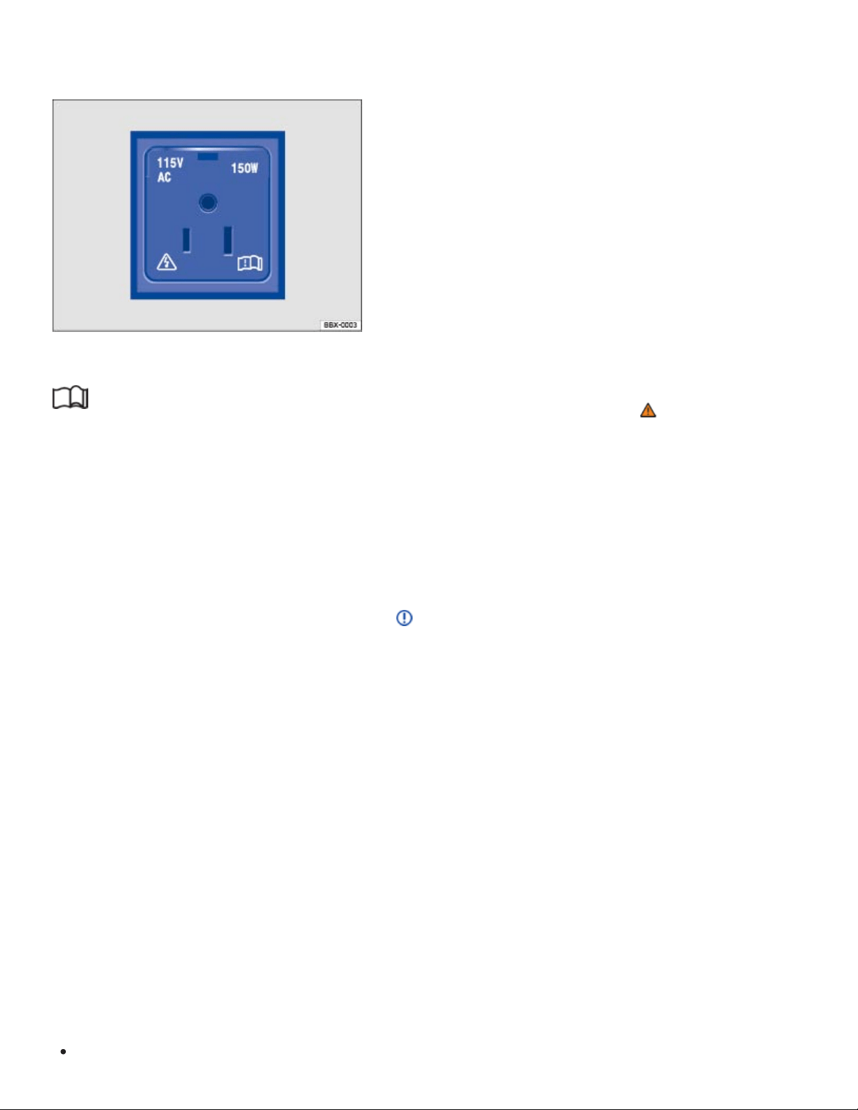
12Volts
115 Volts
Fig.152In the lower center console, in the rear center console, or on the left side of the luggage
compartment: 12 Volt socket with cover.
Fig.153Rear center console: Open cover for access to the 115 Volt outlet (if equipped).
Read and follow the introductory information and safety information first⇒ Introduction to the
subject
Maximum power draw
120watts
150 watts (300 watts peak consumption)
If 2or more electrical devices are connected at the same time, the total power draw of all connected
devices must never be more than 190watts ⇒ .
The maximum power draw at any one socket must never be exceeded. Electrical devices should
have information on them that says how much power they draw.
12Volt socket
The 12Volt socket works only when the ignition is switched on.
If the ignition is on but the engine is not running, the vehicle battery will be drained by any device that
is plugged in and turned on. For this reason, never use the electrical sockets unless the engine is
running.
To help prevent damage from voltage fluctuations, switch off all electrical devices connected to a
12Volt socket before switching the ignition on or off or starting the engine.
The vehicle may have 12Volt sockets at the following places:
In the lower center console ⇒Fig.148 .

Green continuous light:
Green flashing light:
Red flashing light:
In the rear center console.
On the left side of the luggage compartment.
115 Volt socket
The socket automatically switches on when the engine is switched on and a plug is inserted. If there
is enough electricity available, the socket can still be used after the engine has been switched off ⇒
.
Connecting an electrical device: Open the cover and insert the plug as far as it goes into the outlet in
order to unlock the integrated childproof lock. There is electricity in the outlet only after the childproof
lock is unlocked.
LED display on the outlet
The child-proof lock is unlocked. The outlet is operational.
The ignition is switched off, but there is enough electricity available to power
the socket for up to 10 more minutes. If the plug is removed during this time, the socket is
switched off and cannot be used again until the ignition is switched on again.
Malfunction, such as cutoff due to current overload or overheating.
Overheating cutoff
The inverter in the 115 Volt outlet shuts off automatically above a certain temperature. The shutoff
prevents overheating in case of excessive power consumption of connected devices or at high ambi‐
ent air temperatures. The inverter may be used again after a cool-down period. To use the 115 Volt
outlet after the cool-down period, remove the plug from the outlet and reinsert it. This prevents previ‐
ously plugged in devices from switching on unnoticed.
DANGER!
Improper use of the 115 Volt outlet can cause electrical shock, burns, and severe personal injury.
Never spill liquids on the socket.
Never plug an adapter or an extension cord into the 115 Volt outlet. Otherwise, the integrated
child-proof lock is switched off and the outlet is live.
Never stick anything that conducts electricity, such as a knitting needle, into the contacts of the
115 Volt outlet.

NOTE
Follow the manufacturer's instructions for connected devices!
Never exceed the maximum power consumption, or the entire vehicle electrical system may
be damaged.
12Volt socket:
Only use equipment that has been tested for electromagnetic compatibility and
complies with applicable guidelines.
Never feed current into the socket, with a solar panel, for example.
115 Volt outlet:
Do not connect devices or plugs which are too heavy, such as a grid power supply
adapter or cord, directly onto the outlet.
Do not connect lamps containing fluorescent tubes.
Only connect devices to the outlet with voltage consistent with the voltage of the outlet.
For devices with a high starting current, the integrated over-current shutoff will prevent
them from being switched on. In this case, disconnect the power supply from the device
and reconnect after about 10seconds.
Unshielded devices may interfere with radio reception or the vehicle's electrical system.
Media and audio components
USB ports
Depending on equipment, the USB ports in the vehicles may be marked with the following symbols:
USB port with charging capabilities
USB port with charging and data transfer capabilities
USB ports may be in the following places in the vehicle:
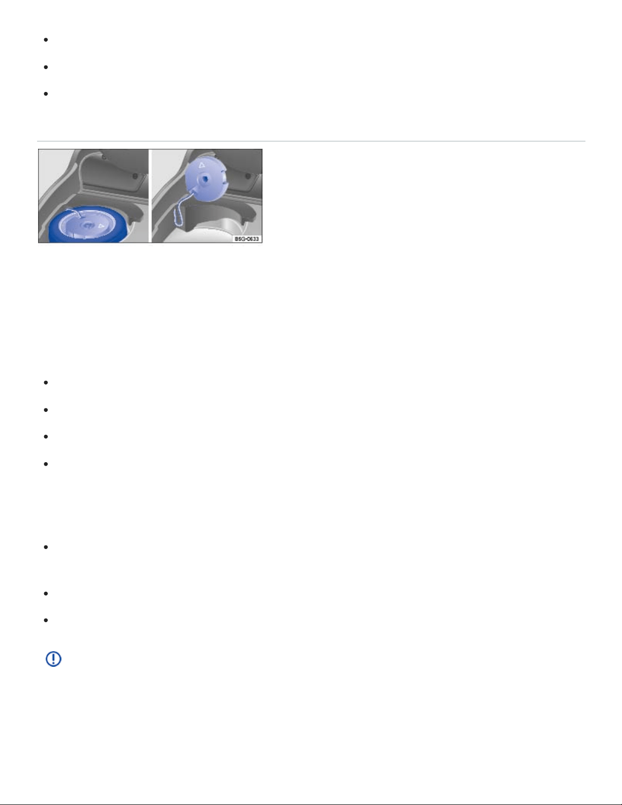
In the front center console storage compartment.
In the storage compartment between the front seats.
In the rear center console.
Subwoofer
Fig.154Under the luggage compartment floor: Subwoofer (if equipped)
The subwoofer (if equipped) is under the luggage compartment floor and must be removed to access
the spare wheel.
Removing the subwoofer
Raise and secure the luggage compartment floor ⇒Luggage compartment floor .
Unscrew the handwheel counterclockwise.
Carefully lift up the subwoofer.
Lean the subwoofer against the side of the luggage compartment. Make sure that the subwoofer
does not fall over ⇒Fig.154 .
Reinstalling the subwoofer
Place the subwoofer carefully back into the recess. The arrow symbol FRONT on the subwoofer
must point toward the front of the vehicle.
Screw the handwheel clockwise as far as it will go.
Carefully lower the luggage compartment floor back into place.
NOTE
The subwoofer can be damaged if the subwoofer plug is disconnected or the connecting cable is
trapped or kinked.
Data transfer

Cybersecurity
Your vehicle contains many components that can send and receive information. They are connected
to different networks to make navigation, communication, and online services, such as Car-Net,
possible.
Onboard Diagnostic port
Control units with integrated eSIM card
Volkswagen Car-Net control unit
Mobile phone interface
Media control
App-Connect
WiFi hotspot
Bluetooth connection
USB port
SD card slot
SIM card slot
These are key components equipped with cybersecurity measures that help prevent unauthorized
and unlawful access to vehicle systems. However, no vehicle or system is absolutely immune from
illegal or unauthorized access and misuse, particularly as cybersecurity risks evolve over time.
Therefore, you may be contacted by Volkswagen or an authorized Volkswagen dealer or authorized
Volkswagen Service Facility regarding the need to update software to help prevent unauthorized and
unlawful access to vehicle systems. It is important that you as the vehicle owner or lessee keep your
contact information up-to-date so that you can be notified.
Frequently change passwords using combinations of letters, numbers, and symbols that are hard
to guess.
Have the vehicle serviced, repaired, and maintained only by a qualified workshop. Volkswagen
recommends using an authorized Volkswagen dealer or authorized Volkswagen Service Facility
for this purpose.
Never connect any devices that do not come from known and trusted sources to the Onboard
Diagnostic II port on your vehicle. This port is required by law and is used by authorized techni‐

cians to get information about the performance of your vehicle’s emissions controls. Attaching
other devices can cause malicious software to be directly introduced into the vehicle and its
systems.
Only connect media (USB flash and other drives, electronic devices, SD and other memory cards,
etc.) from known and trusted sources to your vehicle to help prevent malicious software from be‐
ing introduced into your vehicle.
Always make sure that only apps from known and trusted sources are installed on smartphones
and other devices that are connected to your vehicle or that are to be installed into vehicle
systems.
WARNING
The introduction of malicious software into the vehicle and its systems can impair safety-related
vehicle functions and cause loss of vehicle control, a crash, and serious personal injury or death,
as well as potential data loss. To help minimize the potential risk of security breaches:
Never connect – or allow others to connect – electronic devices or media such as USB flash
drives to the vehicle unless you are sure that they come from known and trusted sources.
If you believe that your vehicle or its systems may be infected by malicious software, see an
authorized Volkswagen dealer or authorized Volkswagen Service Facility right away.
VW Car-Net Security & Service: Connecting you and your vehicle
Applicable only in the United States
Introduction to the subject
In this chapter you will find information on the following subjects:
⇒VW Car-Net® Security & Service
⇒Application software (“apps”)
⇒3-button module
VW Car-Net Security & Service is provided by Verizon Telematics, Inc. (VzT). Automatic Crash
Notification (ACN) for new vehicles may be enabled for up to 6 months without activating a trial or
paid subscription. ACN for Certified Pre- Owned vehicles is available for a 3 month trial which can be
enabled by contacting a VW Car-Net Security & Service Customer Specialist. Manual Emergency
®
®

Call service and all other VW Car-Net Security & Service features require a trial or paid subscription.
VW Car-Net Security & Service requires vehicle cellular connectivity and availability of vehicle GPS
signal. VW Car-Net Security & Service may collect location information. See applicable Terms of
Service and Privacy Policy available at www.vw.com/carnet for details.
Data Collection and Privacy
Vehicle location information is transmitted to Volkswagen and our VW Car-Net Security & Service
provider, Verizon Telematics, Inc. (VzT) anytime you press a VW Car-Net in-car button, when an ACN
event occurs, or periodically in connection with the operation of VW Car-Net Security & Service.
Unless VW Car-Net Security & Service equipment is disabled in the vehicle, it is possible for
Volkswagen and VzT to determine the car’s location if required to do so by law, court order, sub‐
poena, or other legal requirement. For more information, please contact the VW Car-Net Response
Center at 1-877-820-2290.
Calls may be monitored or recorded.
Volkswagen collects, processes, transmits, uses and shares information about you and your vehicle
in accordance with the VW Car-Net Security & Service Terms of Service and Privacy Policy. See the
VW Car-Net Security & Service Terms of Service and Privacy Policy at (http://www.vw.com/carnet) for
more details.
WARNING
Application software and VW Car-Net Security & Service features that are unsuitable or improp‐
erly used can cause accidents, serious personal injury and vehicle damage.
VW Car-Net Security & Service features can be used only where adequate cellular and GPS
signals are available
Volkswagen recommends using only services and application software that are provided by
Volkswagen or Verizon Telematics, Inc. (VzT) specifically for your vehicle.
Protect the mobile device and its application software from misuse.
Never modify application software and VW Car-Net Security & Service features.
Always read and heed the operating instructions for the mobile device.
WARNING
®
®

Driver distraction causes accidents, collisions and serious personal injury! Using application soft‐
ware and VW Car-Net Security & Service features while driving can distract the driver from
traffic.
Always drive attentively and responsibly.
Applicable only in the United States
VW Car-Net Security & Service
Read and follow the introductory information and safety information first⇒ Introduction to the
subject
Your vehicle has equipment to enable VW Car-Net Security & Service, a suite of connected vehicle
services that makes driving and owning a Volkswagen vehicle more convenient. VW Car-Net Security
& Service allows you to seamlessly connect your car and your life by offering the following services:
Safe & Secure – Automatic Crash Notification, Roadside Assistance, Manual Emergency Call,
and Stolen Vehicle Location offers support and assistance when you need it most.
Family Guardian – Create Speed, Boundary, Curfew, or Valet alerts for peace of mind when your
teen driver is at the wheel.
Remote Vehicle Access – Check your vehicle status, lock your doors, honk and flash, and view
your last parked location through a compatible smartphone using the VW Car-Net Security &
Service mobile app (text and data rates may apply).
Diagnostics & Maintenance – Manage your vehicle health with diagnostic checks and service
scheduling.
You can access VW Car-Net Security & Service via your VW Car-Net iPhone or Android app (text
and data rates apply) and the VW Car-Net Security & Service website (http://www.vw.com/carnet). If
you have a question or would like to subscribe, please either press the ⇒Fig.155① button in your
vehicle or contact the VW Car-Net Security & Service Response Center at 1-877-820-2290. For more
information or to log on to your VW Car-Net Security & Service account, visit
http://www.vw.com/carnet.
Note: Please review the VW Car-Net Security & Service Terms of Service and Privacy Policy at
http://www.vw.com/carnet.
Subscription required
®
®
®
® ® ®

Automatic Crash Notification (ACN) may be engaged for up to 6 months, starting from the date of new
vehicle sale, without activating a trial or paid subscription.
The Manual Emergency Call service and all other VW Car-Net Security & Service features require a
trial or paid subscription. To begin your trial or paid subscription, authentication and activation are re‐
quired. For more information, please visit the website (http://www.vw.com/carnet), press the
⇒Fig.155① button in the 3-button module in your vehicle, or contact the VW Car-Net Security &
Service Response Center at 1-877-820-2290.
The LED light in the 3-button module will be green during the trial period and whenever you have an
active subscription ⇒3-button module .
Once a trial or paid VW Car-Net Security & Service subscription has been activated, please ad‐
vise all who use the vehicle that different kinds of data can be sent and received automatically
by the vehicle, including speed, location and more.
WARNING
Vehicle health reports do not replace the information provided by the vehicle warning and indica‐
tor lights. Failure to heed warning lights and instrument cluster text messages can result in a colli‐
sion and serious personal injury.
Always consult vehicle literature for maintenance guidelines.
Never ignore warning lights or text WARNINGS.
Always stop the vehicle as soon as it is safe to do so.
Park the vehicle at a safe distance from moving traffic and where no part of the hot catalytic
converter and exhaust system can come into contact with flammable materials under the vehi‐
cle, such as dry grass, brush, spilled fuel, etc.
A broken down vehicle presents a high accident risk for itself and others. Switch on emer‐
gency flashers and set up a warning triangle to warn oncoming traffic.
Before opening the engine hood, always switch off the engine and let the engine cool down.
Always be very careful when working in the engine compartment, which is a potentially dan‐
gerous area in any motor vehicle and can cause serious personal injury.
NOTE
Failure to heed warning lights or text WARNINGS can result in vehicle damage.
®

Volkswagen collects, processes, transmits, uses and shares information about you and your vehi‐
cle in accordance with the VW Car-Net Security & Service Terms of Service and Privacy Policy.
See the VW Car-Net Security & Service Terms of Service and Privacy Policy at
http://www.vw.com/carnet for more details.
VW Car-Net Security & Service features use a system based on a wireless communication net‐
work. If all technical and other conditions are met and VW Car-Net Security & Service still does
not work properly, please try using the service again later.
The VW Car-Net Security & Service website (http:// www.vw.com/carnet) contains the most up-
to-date information and instructions about VW Car-Net Security & Service features.
Please regularly visit the website to learn about changes to services and new features.
VW Car-Net Security & Service features can be modified, discontinued, deactivated, reactivated
or expanded without any further notice.
Applicable only in the United States
Application software (“apps”)
Read and follow the introductory information and safety information first⇒ Introduction to the
subject
Many mobile devices are equipped to load application software (apps) into the device. Apps can
make it possible to display additional information on the factory-installed Radio or Navigation system
or activate, control or deactivate specific vehicle features.
Application software, its usage and the wireless connection required to use application software may
be billable services. Apps may be provided by third parties. Therefore you should refer to the terms of
use and privacy statements associated with the apps for information about how the apps collect, use
and share information about you, your vehicle or your mobile device.
The application software provided may be designed to be used for a variety of purposes and be spe‐
cific to your vehicle and country ⇒ . The content, range of software provided and application soft‐
ware provider can vary. Some application software is also subject to the availability of services pro‐
®
®
®
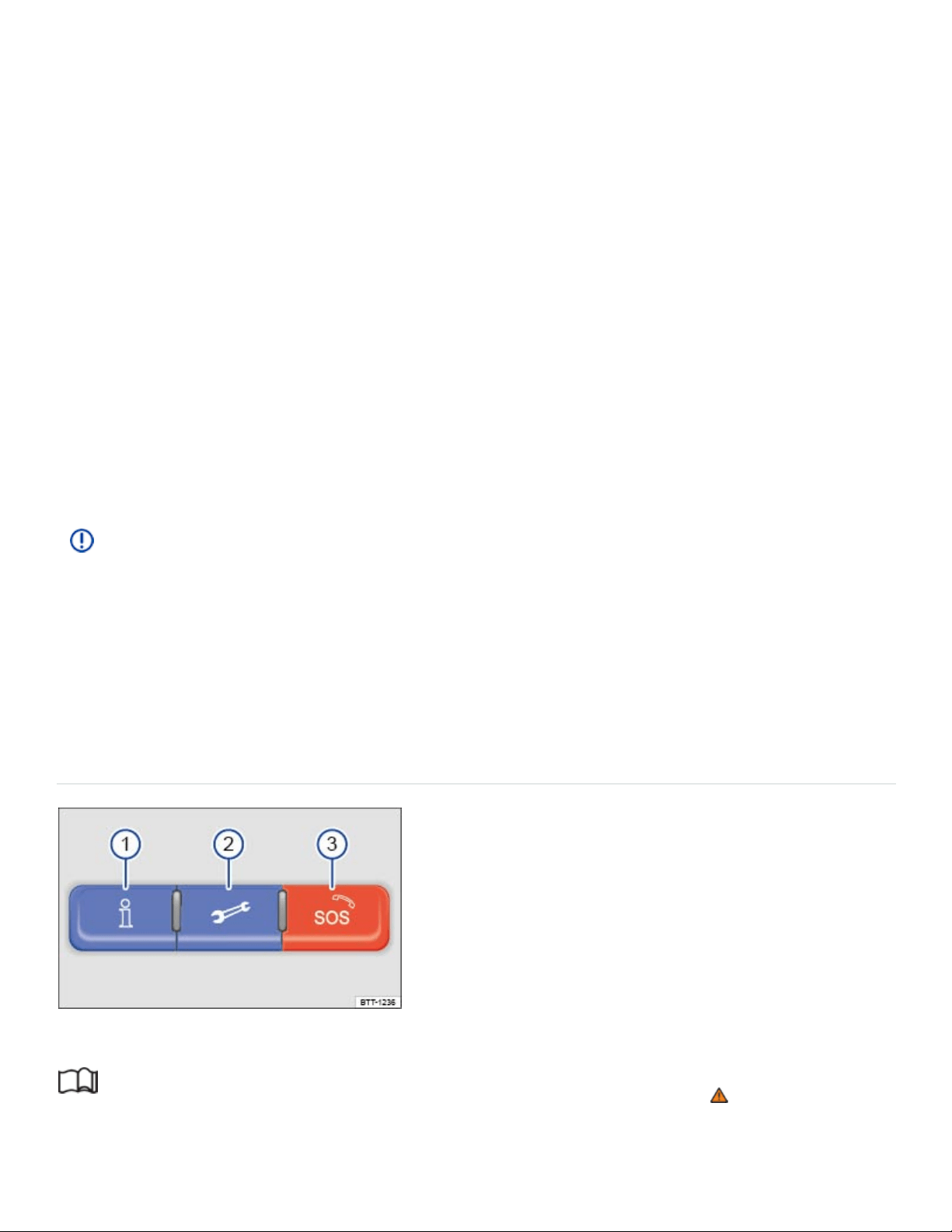
vided by third parties. In order for some application software to work, wireless service reception must
be strong enough to handle the data exchange involved (text and data rates apply).
Application software descriptions may be provided by the service provider.
Due to the multitude of mobile devices and fast pace of software development, the application soft‐
ware provided may not run on all mobile devices and their operating systems. This may even apply
for the same model of a mobile device. For example, application software may run on version 2 of the
device's operating system but not on version 3.
Application software can be modified, discontinued, deactivated, reactivated or expanded without any
further notice.
In order for some application software to work, the wireless or cable connection between the factory-
installed Radio or Navigation system and a compatible, functioning mobile device must be strong
enough and uninterrupted.
NOTE
Volkswagen is not responsible for vehicle damage caused by inferior-quality or malicious applica‐
tion software, poorly programmed application software, insufficient wireless service reception,
data loss during transmission or misuse of mobile devices.
Applicable only in the USA
3-button module
Fig.155In the roof console: 3-button module to connect to VW Car-Net Security & Service operators.
Read and follow the introductory information and safety information first⇒ Introduction to the
subject

The buttons in the 3-button module provide access to several VW Car-Net Security & Service fea‐
tures and pressing a button will initiate a connection to the VW Car-Net Security & Service Response
Center. Calls may be monitored or recorded. In general, the VW Car-Net Customer Specialist will end
the call.
Key to ⇒Fig.155 :
Connects to Customer Specialist at the VW Car-Net Security & Service Response Center.
Connects to the Volkswagen Roadside Provider for assistance in the event of a breakdown.
Activates an emergency call.
To begin a call: Press and hold the relevant button for longer than 2 seconds.
To end the call: Press the button again.
LED light in the 3-button module
The LED light in the 3-button module will be green during the trial period and whenever you have an
active subscription. The LED light will go off if the trial period is over and the customer has not sub‐
scribed to the VW Car-Net Security & Service. The LED light will be red only during a VW Car-Net
hardware malfunction or fault.
WARNING
Application software and VW Car-Net Security & Service features that are unsuitable or improp‐
erly used can cause accidents, serious personal injury and vehicle damage.
VW Car-Net Security & Service can be used only where adequate cellular and GPS signals
are available
Volkswagen recommends using only services and application software that are provided by
Volkswagen or Verizon Telematics, Inc. (VzT) specifically for your vehicle.
Protect the mobile device and its application software from misuse.
Never modify application software and VW Car-Net Security & Service features.
Always read and heed the operating instructions for the mobile device.
WARNING
Driver distraction causes accidents, collisions and serious personal injury! Using application soft‐
ware and VW Car-Net Security & Service features while driving can distract the driver from
®
®
®
®
®

traffic.
Always drive attentively and responsibly.
NOTE
The system does not support simultaneous VW Car-Net Security & Service and mobile phone
calls via the mobile phone package.
When a VW Car-Net Security & Service feature is accessed through the 3-button module call
buttons, any calls on a mobile device connected to the vehicle’s mobile phone package will be
automatically disconnected.
Initiating or accepting a call on a mobile device connected to the vehicle's mobile phone pack‐
age could end any connection to the VW Car-Net Security & Service Response Center made
through the 3-button module.
Calls on a mobile device connected to the vehicle's mobile phone package cannot be ac‐
cepted or initiated during an automated emergency connection to the VW Car-Net Security &
Service Response Center; for example, because an airbag has deployed.
Transporting
Stowing luggage
Luggage and heavy items may be stored in the luggage compartment, in a trailer ⇒Trailer towing , or
on a roof rack ⇒Roof rack .
Always stow all luggage securely in the vehicle
Distribute the load in the vehicle as evenly as possible.
Put heavy objects as far forward as possible in the luggage compartment and securely latch the
rear seat backrest in the upright position.
Never exceed the Gross Axle Weight Rating or the Gross Vehicle Weight Rating ⇒Weights and
axle weights .
Secure luggage in the luggage compartment using suitable straps and the tie downs ⇒Tie-
downs .
Securely stow small objects as well.
If necessary, fold the rear seats forward and latch securely.
®

Adjust the headlight range, if necessary ⇒Lights .
Check the pressure in all 4tires when the tires are still cold. Never reduce air pressure in warm
tires to match cold tire inflation pressure. Heed the information on the tire pressure label ⇒Tires
and wheels .
Pay especially close attention to your vehicle's Tire Pressure Monitoring System when driving with
a heavy load ⇒Tire Pressure Monitoring System (TPMS) .
WARNING
Unsecured or incorrectly stowed items can fly through the vehicle, causing serious personal in‐
jury during hard braking or sharp steering or in an accident. Loose items can also be struck and
thrown through the passenger compartment by the front airbags if they inflate. To help reduce the
risk of serious personal injury:
Always stow all objects securely in the vehicle. Always put luggage and heavy items in the lug‐
gage compartment.
Always secure objects in the passenger compartment properly with suitable straps so that they
cannot move into the deployment area of a side or front airbag during braking, in a sudden
maneuver, or in a collision.
Always keep storage compartments closed while driving.
Never stow hard, heavy, or sharp objects in the vehicle's open storage compartments, on the
luggage compartment cover, or on the top of the instrument panel.
Always remove hard, heavy, or sharp objects from clothing and bags in the vehicle interior and
stow them securely in the luggage compartment.
Passengers must never ride in an incorrect seating position because objects are being trans‐
ported in the vehicle.
Never let anybody sit in a seat that is blocked by objects being carried in the vehicle.
Never let anyone ride in the luggage compartment.
WARNING
Transporting heavy objects causes the handling characteristics of the vehicle to change and in‐
creases braking distances. Heavy loads which are not properly stowed or secured in the vehicle
can lead to a loss of vehicle control and cause serious personal injury.

Transporting heavy items causes the handling characteristics of the vehicle to change by shift‐
ing the vehicle's center of gravity.
Always distribute luggage evenly and as low as possible within the vehicle. The vehicle capac‐
ity weight figures apply when the load is distributed evenly in the vehicle (passengers and
luggage).
Always stow luggage and heavy items in the luggage compartment as far forward of the rear
axle as possible and secure them with appropriate straps to the tie-downs provided.
Secure the load properly to keep it from shifting.
Never exceed the vehicle's Gross Vehicle Weight Rating or Gross Axle Weight Ratings, which
are printed on the Safety Compliance Certification Label located on the door jamb of the driver
door. Exceeding the permissible weight can cause the vehicle to skid and behave differently.
Always adapt your speed and driving style to accommodate your payload and its weight distri‐
bution within your vehicle.
Be especially cautious and gentle when stepping on the accelerator pedal and avoid sudden
braking and other maneuvers.
Brake earlier than you would if you were not driving a loaded vehicle.
NOTE
The defroster heating wires or antenna in the rear window can be damaged by objects that rub
against them.
The ventilation slots in the luggage compartment must not be blocked so that stale air can es‐
cape from the vehicle.
Luggage compartment floor
Luggage compartment floor – features
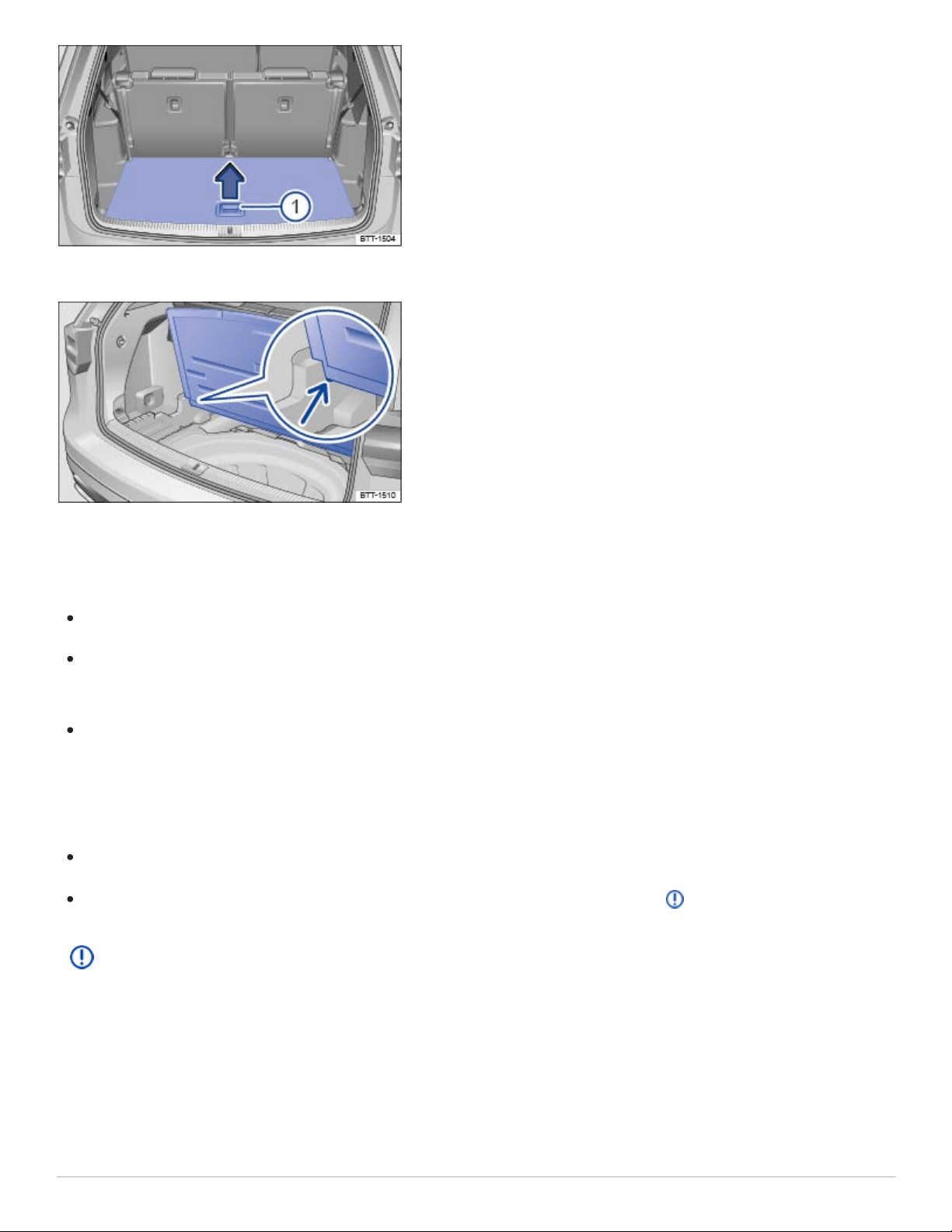
Fig.156In the luggage compartment: Opening the luggage compartment floor.
Fig.157In the luggage compartment: Holding the luggage compartment floor in place.
Opening the luggage compartment floor
If necessary, remove the luggage net .
Grasp the handle in the luggage compartment floor ⇒Fig.156① and lift the floor in the direction
of the arrow.
To keep the luggage compartment floor raised, place it in the brackets on the sides of the luggage
compartment ⇒Fig.157 (arrow).
Closing the luggage compartment floor
Remove the raised luggage compartment floor out of the side brackets.
Guide the luggage compartment floor gently downward into position ⇒ .
NOTE
Do not let the luggage compartment floor fall freely when closing it. Always guide it down into
place. The trim or the luggage compartment floor could be damaged.
Luggage compartment – features
Tie-downs
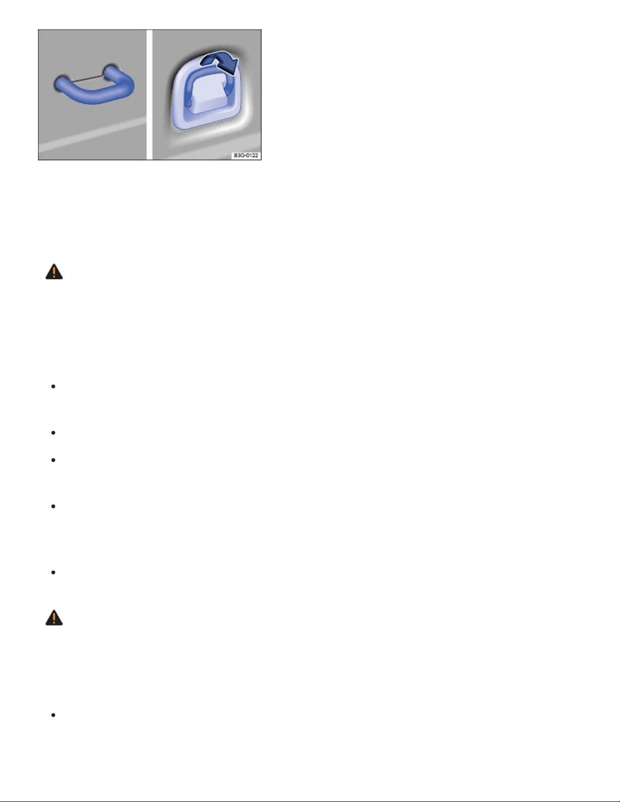
Fig.158In the luggage compartment: Tie-downs.
There are tie-downs in the luggage compartment, which you can use to secure luggage or other items
⇒Fig.158 .
WARNING
Unsuitable, worn, or damaged tie-down straps (elastic or non-elastic) can snap or come loose
during braking or other maneuvers or in a collision. Objects secured with these straps can then
come loose and fly through the passenger compartment, causing severe personal injuries or
death.
To help prevent baggage or other items from coming loose and flying around, always use suit‐
able undamaged tie-down straps.
Securely fasten the tie-down straps to the tie-downs.
Loose or improperly secured objects in the luggage compartment can slide about suddenly
and change the vehicle's handling.
Secure even small and light objects. Loose objects in the luggage or passenger compartment
can fly about during sudden braking maneuvers or in the event of an accident and injure
occupants.
Never attach a child restraint to the tie-downs.
WARNING
Elastic straps have to be stretched when being attached to the tie-downs in the luggage compart‐
ment. Hooks on these straps can cause serious personal injury if not handled properly and at‐
tached securely.
Always protect eyes and face from injury from the hooks when attaching them to the tie-downs
in the luggage compartment.
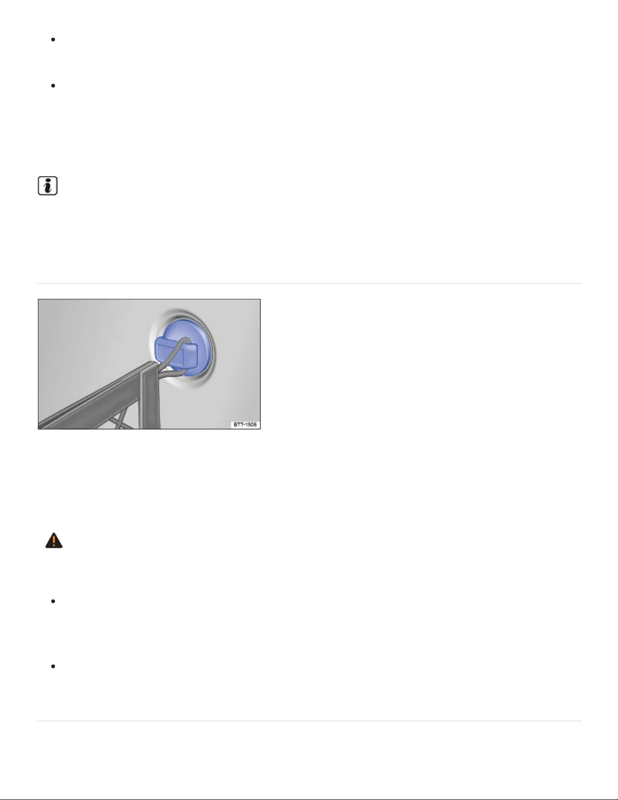
Always hold the hooks on elastic straps firmly when attaching to the vehicle and do not let
them snap back and hit you.
First attach the hooks on the straps to the tie-downs at the rear seat backrest in the luggage
compartment and then to the tie-downs near the loading edge of the luggage compartment.
This way, if one of the hooks on the elastic straps snaps back, it will move away from you, de‐
creasing the risk of personal injury.
For suitable straps and luggage stowage systems, please see an authorized Volkswagen dealer
or authorized Volkswagen Service Facility.
Luggage net hooks
Fig.159In the luggage compartment: Luggage net hooks
The luggage net hooks are on the sides on the luggage compartment ⇒Fig.159 and can be used to
install a luggage net.
WARNING
Only use the luggage net hooks to install the luggage net.
The improper use of the luggage net hooks can cause the luggage net hooks to break during
braking or other maneuvers or in a collision. This could let objects fly through the passenger
compartment during sudden braking or in a crash causing serious personal injury.
Never attach a child restraint to the luggage net hooks.
Shopping bag hook
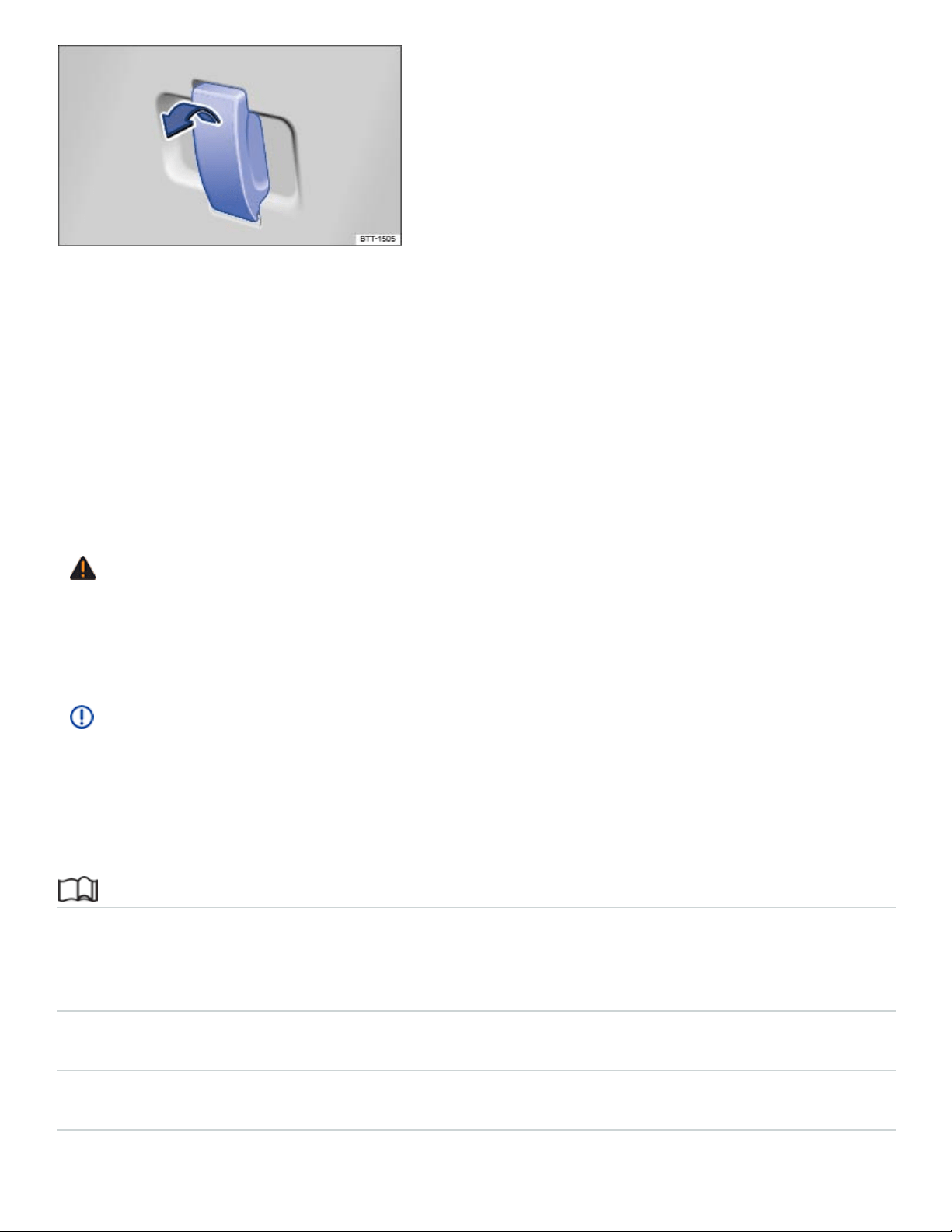
Fig.160In the luggage compartment: Shopping bag hook.
The foldable shopping bag hook in the luggage compartment can hold light shopping bags
⇒Fig.160 .
Folding the shopping bag hook down and back up
To fold down: pull the hook in the direction of the arrow.
To fold back up: push the hook in the opposite direction of the arrow.
WARNING
Never use the shopping bag hook as tie-downs. The hooks could break during sudden braking or
in a collision.
NOTE
The maximum load for the shopping bag hook is 5lbs. (2.5kg).
Roof rack
Introduction to the subject
In this chapter you will find information on the following subjects:
⇒Attaching the roof rack base carrier and roof rack
⇒Securing a load on the roof rack
⇒Tips and troubleshooting
The roof rack can be used to transport bulky loads on the roof of the vehicle.
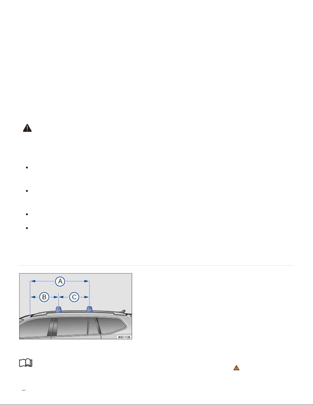
Special considerations for the roof rack
The roof of your vehicle has been designed to optimize aerodynamics and does not have traditional
rain gutters that are used to attach many kinds of roof racks.
Since the rain gutters are molded into the roof to provide efficient aerodynamics, only Volkswagen-
approved base carrier mountings and roof racks can be used.
The weight of the roof rack and the cargo being carried on it reduce the remaining load your vehicle
can carry. Always follow the steps for determining the correct load limit ⇒Determining the correct
load limit .
WARNING
Transporting heavy or bulky loads on the roof rack will change the way the vehicle handles by
raising the vehicle's center of gravity and increasing the wind drag.
Always secure the load properly with suitable and undamaged straps so that the load will not
shift.
Cargo that is large, heavy, bulky, long or flat will have a negative effect on the vehicle's aero‐
dynamics, center of gravity and overall handling.
Always avoid sudden maneuvers and hard braking.
Always adapt your speed and driving to the heavier load and the weight distribution in the ve‐
hicle. Take road, weather, traffic, and visibility conditions into account as well.
Attaching the roof rack base carrier and roof rack
Fig.161On the vehicle roof: measurements for attaching the roof rack.
Read and follow the introductory information and safety information first⇒ Introduction to the
subject

54.02 inches (1.37 m)
24.37 inches (0.62 m)
29.65 inches (0.75 m)
The base carrier is the basis of a complete roof rack system. For safety reasons, additional attach‐
ments are necessary for transporting luggage, bicycles, surfboards, skis, and small boats. Suitable
accessories can be purchased from your authorized Volkswagen dealer or authorized Volkswagen
Service Facility.
Mounting the roof rack
Only roof racks which have been approved by Volkswagen may be attached to the roof rails.
Always carefully follow the installation instructions from the base carrier or roof rack manufacturer.
The provided dimensions ⇒Fig.161 may be used as a guideline for installing the base carrier or
roof rack.
If you are uncertain about mounting the roof rack, contact your authorized Volkswagen dealer or
authorized Volkswagen Service Facility.
WARNING
Installing or using a base carrier or roof rack improperly can cause the entire system to fly off the
vehicle, causing accidents and injuries.
Always follow the installation instructions provided by the manufacturer.
Use the base carrier and roof rack only if they are undamaged and properly installed.
Secure the roof rack base carrier only at the measurements shown in the illustration.
Always install the base carrier and roof rack properly.
Make sure that all bolts and fasteners are properly installed and properly tightened before ev‐
ery trip; and retighten them as needed after driving a short distance. During a long trip, check
all bolts and fasteners at each stop.
Always properly install special fixtures for items such as bicycles, skis, surfboards, etc.
Do not modify or repair the base carrier or roof rack.
Securing a load on the roof rack

Read and follow the introductory information and safety information first⇒ Introduction to the
subject
It is not possible to secure a load properly unless the roof rack system has been properly installed ⇒
.
Maximum permissible roof load
The maximum permissible roof load is 200lbs. (90 kg).
The maximum permissible roof load is the combined weight of the roof rack and the items being car‐
ried on the roof ⇒ .
Be sure you know the weight of the roof rack and the items you want to transport on the roof. Weigh
them if necessary. Never carry a total of more than the maximum permissible roof load.
When using a roof rack with a lower load limit, do not load the rack to the maximum weight mentioned
above. In this case, you may only load the roof rack to the weight limit specified in the system's instal‐
lation instructions.
Distributing the load
Distribute the load evenly and secure it properly ⇒ .
Checking the mountings
After the base carrier and roof rack have been installed, check all bolts and fasteners after driving a
short time and at regular intervals thereafter.
WARNING
If the maximum permissible roof load is exceeded, accidents and substantial vehicle damage
may occur.
Never exceed the specified roof load, the maximum Gross Axle Weight Rating, or the Gross
Vehicle Weight Rating.
Do not exceed the loading capacity of the roof rack, even if the permissible roof load is not
fully utilized.
Always make sure that loads are evenly distributed and that heavier items are, as far as possi‐
ble, toward the front.

WARNING
Loose or improperly secured items can fall off the roof rack and cause accidents and injuries.
To help prevent baggage or other items from coming loose and flying around, always use suit‐
able, undamaged tie-down ropes and ratchet straps.
Secure the load properly.
NOTE
When opening the trunk lid, make sure that it will not hit anything secured to the roof rack.
Tips and troubleshooting
Read and follow the introductory information and safety information first⇒ Introduction to the
subject
When to remove the roof rack
When it is no longer needed.
Before driving through an automatic car wash.
When the vehicle would otherwise be too high for minimum clearance to enter, for example, a
garage.
NOTE
Always remove the roof rack before driving through an automatic car wash.
Your vehicle is higher when the roof rack is installed, especially when it is loaded. Compare
the vehicle height with existing clearance heights, such as underpasses and garage doors.
Always make sure that the roof rack system and anything being carried on it does not interfere
with the roof antenna, the power sunroof, or the trunk lid.
Make sure that the trunk lid does not touch items on the roof rack when opened.
If a roof rack is installed, fuel consumption increases due to increased air resistance.
Trailer towing

Introduction to the subject
In this chapter you will find information on the following subjects:
⇒Technical requirements
⇒Hitching up and connecting a trailer
⇒Loading the trailer
⇒Driving with a trailer
⇒Ball mount
⇒Retrofitting a trailer hitch
⇒Maximum permissible trailer weight
Obey country-specific requirements about trailer towing and trailer hitches.
Your Volkswagen was mainly designed for carrying passengers. If you plan to tow a trailer, please re‐
member your vehicle will be performing a job for which it was not primarily intended. The additional
load will affect durability, handling, fuel economy, and performance, and may require the vehicle to be
serviced more often.
Trailer towing not only places more stress on the vehicle, it calls for more concentration from the
driver. Always follow the operating and driving instructions given, and use common sense.
If you are unsure if your vehicle has a factory installed or aftermarket installed towing package, al‐
ways ask your Volkswagen dealer or authorized Volkswagen Service Facility for more information be‐
fore towing a trailer.
Under winter conditions, install winter tires on the vehicle and the trailer.
Tongue weight
The maximum permissible trailer tongue weight exerted on the ball mount must not exceed 500lbs
(227kg).
Special considerations for the Start-stop system

Vehicles with a retrofitted trailer hitch: If the trailer hitch was not retrofitted by an authorized
Volkswagen dealer or an authorized Volkswagen Service Facility, then the start-stop system must be
manually switched off by pressing the button when towing a trailer. The start-stop system must stay
deactivated as long as the trailer is being towed ⇒ .
WARNING
Riding in a trailer is dangerous and may be illegal.
WARNING
Improper use of the trailer hitch can cause accidents and injuries. An improperly installed, incor‐
rect, or damaged trailer hitch can cause the trailer to separate from the towing vehicle and cause
serious personal injuries.
Only use an undamaged, properly mounted trailer hitch.
Never repair or modify the trailer hitch.
To reduce the risk of injury in rear-end collisions, and the risk to pedestrians and cyclists when
the vehicle is parked, always remove the ball mount when you are not towing a trailer.
Never install a weight distributing or load equalizing trailer hitch on your vehicle. The vehicle
was not designed for these kinds of trailer hitches. The trailer hitch attachment can fail, caus‐
ing the trailer to tear loose from the vehicle.
WARNING
Improper trailer towing can cause loss of vehicle control and serious personal injury.
Driving with a trailer and carrying heavy or large things can change the way the vehicle han‐
dles, increase the distance it needs to stop safely, and cause accidents.
Always secure the load properly with suitable and undamaged straps so that the load will not
shift.
Always adapt your speed and driving to the heavier load and the weight distribution in the ve‐
hicle. Take road, weather, traffic, and visibility conditions into account as well.
Reduce your speed even more than you otherwise would when going downhill and under unfa‐
vorable load, weather, or wind conditions.
Trailers with a high center of gravity tip more easily than trailers with a low center of gravity.

Always avoid sudden maneuvers and hard braking.
Be especially careful when passing other vehicles.
Reduce speed immediately if the trailer shows the slightest sign of swaying.
Never try to stop the swaying by accelerating.
Always obey speed limits. In some areas, the speed limits for vehicles towing trailers are lower
than for vehicles without trailers. Never drive faster than 50mph (80km/h; under exceptional
circumstances, 60mph - 100km/h) when towing a trailer. This applies even if the local speed
limit is higher.
WARNING
The stop-stop system must always be switched off manually when towing a trailer using a trailer
hitch that was not retrofitted by an authorized Volkswagen dealer or an authorized Volkswagen
Service Facility. Otherwise the brakes could malfunction, causing accidents and severe injuries.
If you are driving a new vehicle or a vehicle with a new or rebuilt engine, do not tow a trailer dur‐
ing the break-in period, about 600miles (1000km) ⇒Break-in period .
If you tow a trailer, your vehicle may need maintenance more often because of the extra load it
has to move.
When you are not towing, remove the trailer hitch ball. This helps keep the trailer hitch from caus‐
ing damage to your vehicle and to others if your vehicle is hit from behind.
Vehicles with a trailer hitch cannot use the towing eye. Instead, the trailer hitch should be used to
tow other vehicles. You may want to carry the ball mount in the vehicle after it has been removed.
Be sure to stow it securely.
Technical requirements
Read and follow the introductory information and safety information first⇒ Introduction to the
subject

Use only a weight-carrying trailer hitch designed and approved for the gross weight of the trailer you
want to tow. The trailer hitch must be suitable for your vehicle and trailer and must be securely bolted
to the appropriate place on the vehicle chassis. Use only a trailer hitch with a removable ball mount.
Always check with the trailer hitch manufacturer to make sure that you are using the correct trailer
hitch and carefully follow the hitch manufacturer's instructions. Never install a weight-distributing or
load-equalizing trailer hitch on your vehicle. The vehicle is not designed for this kind of trailer hitch ⇒
.
Do not use a bumper-mounted trailer hitch
Never install a trailer hitch on the bumper or on the bumper attachments. The trailer hitch must not in‐
terfere with the impact-absorbing bumper system. Do not make any changes to the vehicle exhaust
and brake systems. From time to time, check that all trailer hitch mounting bolts are securely fas‐
tened. When you are not towing, remove the trailer hitch. This helps keep the trailer hitch from caus‐
ing damage if your vehicle is hit from behind.
Engine cooling system
Towing a trailer makes the engine and its cooling system work harder. It is important that the engine
cooling system is up to the job. Make sure that the cooling system has enough coolant.
Trailer brakes
If your trailer has its own brakes, make sure it meets all applicable regulations. The trailer brake sys‐
tem must never be directly connected to the vehicle's brake system.
Outside mirrors
If you cannot see the traffic behind you using the regular outside mirrors, you must install extended
mirrors. Extended mirrors may also be required by law in some countries/states/provinces. Always
adjust the outside mirrors before driving. It's vital that you always have a clear view to the rear of the
vehicle.
Safety chains
Always use safety chains between your vehicle and the trailer ⇒Hitching up and connecting a trailer .
Retrofitting a trailer hitch
Only install a trailer hitch that are approved by Volkswagen for your vehicle and model. Always read
and carefully follow the trailer hitch manufacturer's instructions.

Brake lights total:
Turn signals per side:
Side marker lights total:
Taillights total:
Trailer taillights
Trailer lights must meet all applicable regulations ⇒Hitching up and connecting a trailer .
Never connect the trailer lights directly to the electrical system of your vehicle. Do not exceed the
maximum power ratings listed below:
108watts
54watts
100watts
54watts
WARNING
An improperly installed or incorrect trailer hitch can cause a trailer to separate from the tow ve‐
hicle and cause serious personal injuries.
If you don't have to tow a trailer any more, remove the entire trailer hitch. Always seal all bolt
holes to prevent water and deadly exhaust fumes from getting into the vehicle.
NOTE
If the trailer lights are not connected properly, the vehicle's electronics can be damaged.
If the trailer uses too much electricity, the vehicle's electronics may be damaged.
Never connect the electrical system for the trailer directly to the electrical connections for the
rear lights or to any other unsuitable power sources. Use only a suitable connector to provide
power to the trailer.
If you tow a trailer frequently, Volkswagen recommends having the vehicle serviced between the
regular maintenance and inspection intervals because of the extra load it has to pull.
Hitching up and connecting a trailer
Read and follow the introductory information and safety information first⇒ Introduction to the
subject
Safety chains

Always make sure that the safety chains are properly attached to the towing vehicle. Leave enough
slack in the chains so that you can go around corners without stretching the chains. The safety chains
must not drag on the ground.
The trailer is connected to the anti-theft alarm (if equipped):
When the vehicle has a factory-installed anti-theft alarm and a factory-installed trailer hitch.
When the trailer is electrically connected to the towing vehicle via the trailer socket.
When the vehicle and trailer electric systems are working properly, fault-free and undamaged.
When the vehicle is locked with the remote control vehicle key and the anti-theft alarm is active.
When the vehicle is locked, the alarm will be triggered as soon as the electrical connection to the
trailer is interrupted.
Always switch off the anti-theft alarm when a trailer is being hitched or unhitched. The tilt sensor could
otherwise trigger the alarm unnecessarily.
WARNING
Improper connections to the vehicle electrical system can cause malfunctions that affect the en‐
tire vehicle electrical system, which can lead to accidents and serious personal injury.
Have any work on the electrical system done by an authorized Volkswagen dealer or autho‐
rized Volkswagen Service Facility.
Never connect the electrical system for the trailer directly to the electrical connections for the
rear lights or to any other unsuitable power sources. Use only a suitable connector to provide
power to the trailer.
NOTE
Never attach a trailer to the vehicle or leave it attached to the vehicle when the trailer is sup‐
ported by a trailer jack or blocks. Various things (such as a change in trailer or vehicle load or a
flat tire) can lower or raise the vehicle. This subjects the trailer hitch and the trailer to strong
forces that can damage the vehicle or the trailer.
Any problems with the vehicle's electrical system when attached to a trailer should be checked by
an authorized Volkswagen dealer or authorized Volkswagen Service Facility.

If the engine is switched off and accessories in the trailer are on and use electricity from the vehi‐
cle, the vehicle battery will be drained as long as the electrical systems of the vehicle and the
trailer are connected.
If the 12 Volt vehicle battery is low, the electrical connection to the trailer will be interrupted
automatically.
Loading the trailer
Read and follow the introductory information and safety information first⇒ Introduction to the
subject
Maximum permissible trailer weight and tongue weight
Maximum permissible trailer weight is the load that the vehicle can tow ⇒ .
The tongue load or tongue weight is the load pressing down on the trailer hitch ball mount.
The maximum permissible trailer weight and tongue weight for your vehicle are listed on ⇒Maximum
permissible trailer weight in this Manual.
The trailer load and tongue weight on the type identification plate for the trailer hitch are only test val‐
ues. The vehicle-specific figures are often lower than these values. In some countries, but generally
not in the United States, the vehicle-specific figures are listed in the official vehicle documents.
Specifications in official vehicle documents always take precedence.
To help ensure optimum handling and driving safety, Volkswagen recommends always using the max‐
imum permissible tongue weight. If the tongue weight is too low, the vehicle and trailer will not han‐
dle as well.
Tongue weight increases the load on the rear axle and, in turn, reduces the remaining load your vehi‐
cle can carry ⇒Determining the correct load limit .
Combined towing weight
Combined towing weight is the weight of the loaded towing vehicle plus the weight of the loaded
trailer.

In some cases towing a trailer will lead to a reduced payload due to the limits of the combined towing
weight.
On vehicles with a factory-installed towing package and front wheel drive the combined towing
weight must not exceed 9920 lbs (4501 kg), and with 4-wheel drive the combined towing weight must
not exceed 10150 lbs (4606 kg).
On vehicles without a factory-installed towing package (aftermarket towing package) and front wheel
drive the combined towing weight must not exceed 7730 lbs (3507 kg), and with 4-wheel drive the
combined towing weight must not exceed 7990 lbs (3627 kg).
This vehicle has not been designed to tow a Class IV trailer and must never be retrofitted to tow a
Class IV trailer. Always make sure that your vehicle has been designed to tow the trailer you want to
use and that it is legal to tow the trailer where you will be driving.
Loading the trailer
The weight distribution in the vehicle and trailer must be balanced. Use the maximum permissible
tongue weight and make sure that the load in the trailer is evenly distributed and that it is not front-
heavy or tail-heavy:
Distribute the load in the trailer so that heavy objects are directly above the axle or as close as
possible to the axle.
Secure loads properly on the trailer.
Tire pressure
Always follow the trailer manufacturer's tire pressure recommendations for the trailer tires.
When towing, inflate the towing vehicle's tires to the maximum permissible pressure listed on the tire
pressure label ⇒Tire inflation pressure .
WARNING
Exceeding the gross weight ratings for axle, tongue, vehicle, trailer or combined weight can
cause accidents and serious personal injury.
Never exceed the specified values.
Never let the actual weights at the front and rear axles exceed the Gross Axle Weight Rating.
Never let the combined front and rear weights exceed the Gross Vehicle Weight Rating.

WARNING
Trailer loads that are not properly secured can shift when the vehicle is moving or braking and
suddenly change the way the vehicle handles, causing accidents and severe injuries.
Always load the trailer properly.
Always secure the load properly with suitable, undamaged straps that can be tightened so that
the load cannot shift.
Driving with a trailer
Read and follow the introductory information and safety information first⇒ Introduction to the
subject
Headlight settings
Towing a trailer can raise the front end of the vehicle enough for the low beams to blind other road
users. If necessary, have the headlights adjusted by an authorized Volkswagen dealer or authorized
Volkswagen Service Facility.
Special towing considerations
If the trailer has an overrun brake, apply the brakes gently at first and then firmly. This helps to
prevent sudden brake shock and helps prevent trailer wheels from locking up.
Due to the combined towing weight including the higher gross vehicle weight, the stopping dis‐
tance is longer.
When driving in Tiptronic mode or downhill, especially on hills that are long or steep, shift into a
lower gear so that the engine helps to brake the vehicle. Otherwise, the brake system could over‐
heat and might fail.
The vehicle's center of gravity and, in turn, the vehicle's handling, will change because of the
trailer load and the increased combined towing weight of the vehicle and trailer.
Weight distribution is especially bad if the towing vehicle is empty and the trailer is loaded. If you
absolutely must drive with this combination, drive with extra care and at a reduced speed.
Starting off with a trailer on hills
Depending on how steep the hill is and the combined towing weight, a parked vehicle with trailer can
roll backwards when you first start moving.

When starting off with a trailer on a hill:
Depress and hold the brake pedal.
Pull and hold the switch to use the electronic parking brake to help prevent the vehicle and
trailer from rolling backward ⇒Electronic parking brake .
Shift into Drive (D)⇒Automatic transmission .
Release the brake pedal.
Drive ahead slowly at first.
Do not release the switch until the engine starts to move the vehicle forward.
Drive ahead slowly.
WARNING
Improper trailer towing can cause loss of vehicle control and serious personal injury.
Driving with a trailer and carrying heavy or bulky items changes the way the vehicle handles
and increases the distance it needs to stop safely.
Always watch what is happening up ahead and around you. Brake earlier than you would if
you were not towing a trailer.
Always adapt your speed and driving to the heavier load and the weight distribution in the ve‐
hicle. Take road, weather, traffic, and visibility conditions into account as well.
Reduce your speed even more than you otherwise would when going downhill and under unfa‐
vorable load, weather, or wind conditions.
Drive especially carefully and accelerate gently. Always avoid sudden maneuvers and hard
braking.
Be especially careful when passing other vehicles.
Reduce speed immediately if the trailer shows even the slightest sign of swaying.
Never try to stop the swaying by accelerating.
Always obey speed limits. In some areas speed limits for vehicles towing trailers are lower
than for vehicles without trailers.
Ball mount

Fig.162Dimensions of the ball mount support.
Read and follow the introductory information and safety information first⇒ Introduction to the
subject
If you must tow a trailer, you must have the necessary electrical wiring and socket together with a
suitable trailer hitch installed. Because towing a trailer places a great deal of stress on the vehicle, the
attachment of a trailer to the vehicle and the dimensions of the receiver and ball mount are very im‐
portant so that the extra forces the vehicle has to withstand can be properly handled.
The receiver used requires both a ball mount and a ball that meet special requirements regarding ge‐
ometry and size. This applies to both the drop height of the ball ⇒Fig.162
Ⓐ
, and the pin-to-ball dis‐
tance ⇒Fig.162
Ⓑ
.
These dimensions are important because they help determine the way that the forces that arise dur‐
ing towing are applied to the receiver and its attachments to the vehicle. If you buy a ball mount and
ball, make sure that they meet the following specifications.
Ball mount dimensions
The drop height
Ⓐ
from the top of the ball platform to the top of the shank must be at most 2
inches (50.8 mm).
The pin-to-ball distance
Ⓑ
from the center of the ball to the center of the hole for the securing pin
on the ball mount must be no more than 8 / inches (209.55 mm).
The ball diameter must be no more than 2 inches (50.8 mm).
A ball mount and ball combination that does not meet these specifications can damage your vehicle
and may even fail in use ⇒ .
Never install a weight distributing or load equalizing trailer hitch on your vehicle. The vehicle is not de‐
signed for this kind of trailer hitch ⇒ .
1
4

WARNING
An improperly installed or unsuitable trailer hitch can cause the trailer to separate from the towing
vehicle and result in a major accident with serious personal injuries.
Have any trailer hitch retrofit or other work on a trailer hitch done by a qualified workshop.
CAUTION
The ball mount sticks out behind the rear bumper and can cause injury to pedestrians and
cyclists.
To reduce the risk of injury in rear-end collisions, and the risk to pedestrians and cyclists when
the vehicle is parked, always remove the ball carrier when you are not towing a trailer.
NOTE
Never use a ball larger than 2 inches (50.8mm) on your vehicle. The vehicle was not designed
to tow heavier trailers with a receiver larger than the specified ball. The increased loads can
damage the attachment points for the trailer hitch.
Never use an adapter to increase the size of the trailer hitch receiver from 2inches (50.8mm)
to more to tow a trailer that is heavier than the maximum permissible trailer weight that your
vehicle can tow.
You can use an adapter if required for the proper installation of a bicycle rack or other similar
carrier as long as the maximum weight limits are observed. When using bicycle racks or simi‐
lar carriers, make sure that the rear lights are not blocked.
Only use trailer hitches that are approved by the hitch manufacturer for your vehicle and
model.
Retrofitting a trailer hitch
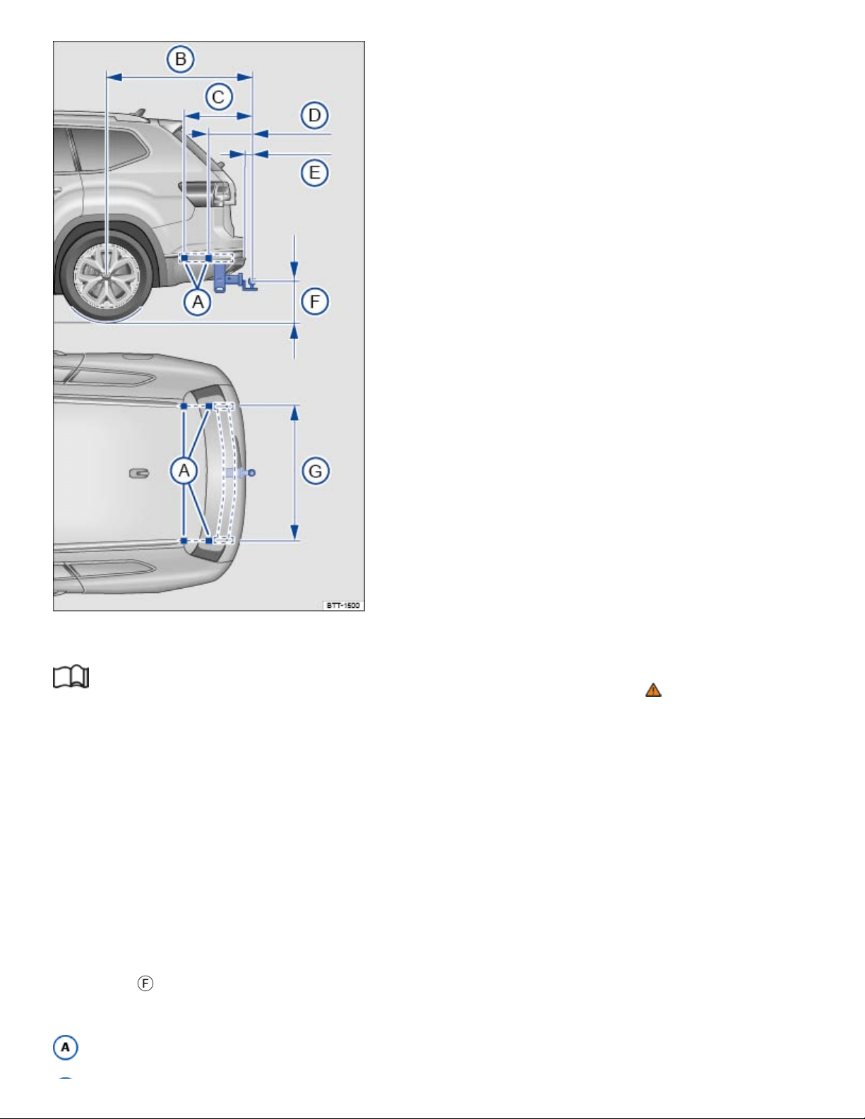
Fig.163Dimensions and attachment points for retrofitting a trailer hitch.
Read and follow the introductory information and safety information first⇒ Introduction to the
subject
Volkswagen recommends having the trailer hitch retrofit performed by a qualified workshop because
cooling system modifications or the installation of heat shields may be necessary. Volkswagen recom‐
mends that you see an authorized Volkswagen dealer or an authorized Volkswagen Service Facility
before having a trailer hitch installed on your vehicle.
Distance dimensions
When retrofitting a trailer hitch, the specified distance dimensions must be strictly adhered to
⇒Fig.163 . Under no circumstances may the distance from the center of the hitch ball to the surface
of the road
Ⓕ
be less than the specified minimum. This minimum height must be present even when
the vehicle is fully loaded and subject to the maximum tongue weight.
Attachment points

51 / inches (1314mm)
24 / inches (620mm)
15 / inches (400mm)
from 2 / inches to 6 / inches (75 - 154mm)
from 13 / inches to 16 / inches (350 - 420mm)
46 / inches (1188mm)
WARNING
Improper or incorrect connections to the vehicle electrical system can cause malfunctions that af‐
fect the entire vehicle electrical system and cause accidents and serious personal injury.
Never connect the electrical system of the trailer directly to the electrical connections of the
rear lights or other unsuitable power sources. Use only a suitable connector to provide power
to the trailer.
Have any trailer hitch retrofit or other work on a trailer hitch done by a qualified workshop.
WARNING
An improperly installed or unsuitable trailer hitch can cause the trailer to separate from the towing
vehicle and result in a major accident with serious personal injuries.
Only use trailer hitches that are approved by Volkswagen for your vehicle and model.
Maximum permissible trailer weight
Read and follow the introductory information and safety information first⇒ Introduction to the
subject
Vehicles with a factory-installed towing package
Maximum permissible trailer weights lbs. kg
Trailer with brake 5000 2268
47
64
13
32
3
4
61
64
1
16
51
64
1
2
49
64
a)b)

Maximum permissible trailer weights lbs. kg
Trailer without brake 1650 748
Tongue weight 500 227
Vehicles with an aftermarket installed towing package
Maximum permissible trailer weights lbs. kg
Trailer with brake 2000 907
Trailer without brake 1650 748
Tongue weight 500 227
The Gross Vehicle Weight Rating and the Gross Axle Weight Rating must not be exceeded, even with
a trailer. These ratings are listed on the safety compliance label on the driver door jamb ⇒Important
vehicle labels .
On vehicles with a factory installed towing package and front wheel drive the combined towing weight
must not exceed 9920 lbs (4501 kg), and with 4-wheel drive the combined towing weight must not
exceed 10150 lbs (4606 kg).
On vehicles without a factory installed towing package (aftermarket towing package) and front wheel
drive the combined towing weight must not exceed 7730 lbs (3507 kg), and with 4-wheel drive the
combined towing weight must not exceed 7990 lbs (3627 kg).
When a trailer is towed, the weight of the ball mount and the tongue weight of the trailer are added to
the vehicle weight ⇒Determining the correct load limit .
The trailer weight ratings given above are valid only up to altitudes of 3000ft (1000m) above sea
level. The maximum permissible combined towing weight must be reduced by about 10% for every
3000ft (1000m), or portion thereof, of additional altitude.
WARNING
a)b)
c)d)
e)

Exceeding the gross trailer weight rating and tongue weight can cause accidents and serious per‐
sonal injury.
Never let the actual weights at the front and rear axles exceed the Gross Axle Weight Rating
(GAWR). Never let the combined front and rear weights exceed the Gross Vehicle Weight
Rating (GVWR).
NOTE
Exceeding the gross weight ratings can cause extensive vehicle damage that is not covered by
any Volkswagen Limited Warranty.
If you are unsure if your vehicle has a factory installed or aftermarket installed towing package,
always ask your Volkswagen dealer or authorized Volkswagen Service Facility for more informa‐
tion before towing a trailer.
For vehicles with front wheel drive: The combined towing weight must not exceed 9920 lbs (4501
kg).
For vehicles with 4-wheel drive: The combined towing weight must not exceed 10150 lbs (4606 kg).
For vehicles with front wheel drive: The combined towing weight must not exceed 7730 lbs (3507
kg)
For vehicles with 4-wheel drive: The combined towing weight must not exceed 7990 lbs (3627 kg).
Vehicles without a factory installed towing package have not been designed to tow a trailer, due to
different technical specs, like the layout of the cooling system Therefore the maximum permissible
trailer weight for a trailer with brakes is limited to 2000 lbs (907 kg).
Fuel and emission control system
Tips on handling fuel
WARNING
Improper refueling or handling of fuel is dangerous and can cause fire, explosion, and severe
burns.
a)
b)
c)
d)
e)

During refueling, the engine and the ignition must be switched off for safety reasons.
Never use a mobile telephone, CB radio, or other radio equipment while refueling. The electro‐
magnetic radiation can cause sparks that can ignite fuel vapors and cause a fire.
Never get back into your vehicle while refueling. If in exceptional circumstances you must get
back in your vehicle while refueling, make certain that you close the door and touch metal to
discharge static electricity before touching the filler nozzle again. This helps avoid the buildup
of static electricity, which can cause sparks that can ignite fuel vapors released during
refueling.
Always make sure that the fuel filler cap is screwed on all the way. This helps keep fuel from
spilling out or evaporating.
Fuel is highly flammable and explosive; it can cause severe burns and other severe injuries.
Failure to shut the engine off while refueling and/or to insert the pump nozzle all the way into
the fuel filler neck can cause fuel to overflow and to spray out. Fuel spray and overflowing fuel
are dangerous because they can cause fire and serious personal injury.
Never smoke or have an open flame (or sparks, cigarettes, or other smoldering objects) any‐
where in or near your vehicle when refueling or filling a portable fuel container.
Follow all safety instructions and procedures that apply at the service station where you refuel.
Never spill fuel in the vehicle or the luggage compartment.
WARNING
Even if empty, portable fuel containers can leak and cause a fire and serious personal injuries,
especially in a crash.
For your safety, we strongly recommend that you do not travel with a portable fuel container in
your vehicle.
If, under exceptional circumstances, you must transport a portable fuel container, please ob‐
serve the following:
Never fill a portable fuel container while it is anywhere in or on the vehicle (for example,
in the luggage compartment or on top of the trunk lid). Static electricity can build up while
filling and can ignite fuel vapors, causing a fire.
Always place a portable fuel container on the ground before filling. Never spill fuel inside
the vehicle or luggage compartment. Fuel vapors are highly flammable.

Always keep the filler nozzle completely inside the portable container before and during
filling.
If filling a portable container made of metal, the filler nozzle must always be in contact
with the container. This will help prevent static electricity from discharging and causing a
fire.
Always observe local and state or provincial laws about the use, storage, and transporta‐
tion of portable fuel containers.
Make certain that the portable fuel container meets industry standards, such as
ANSI/ASTMF852-86.
NOTE
Remove fuel spills from the vehicle immediately to help prevent damage to the paint, tires, and
wheel housings.
Refueling with diesel fuel when your vehicle has a gasoline engine can cause very serious and
expensive engine and fuel system damage that is not covered by any Volkswagen Limited
Warranty.
If you put any amount of incorrect fuel in the fuel tank, do not start the engine under any cir‐
cumstances. Immediately contact the nearest authorized Volkswagen dealer or authorized
Volkswagen Service Facility for assistance. These fuels contain substances that can severely
damage the fuel system and the engine if the engine is started.
Fuels can pollute the environment. Spilled fuel must be collected and disposed of properly, follow‐
ing all applicable environmental regulations.
There is no emergency release for the fuel filler flap. Contact an authorized Volkswagen dealer or
an authorized Volkswagen Service Facility for assistance.
Refueling
Introduction to the subject
In this chapter you will find information on the following subjects:
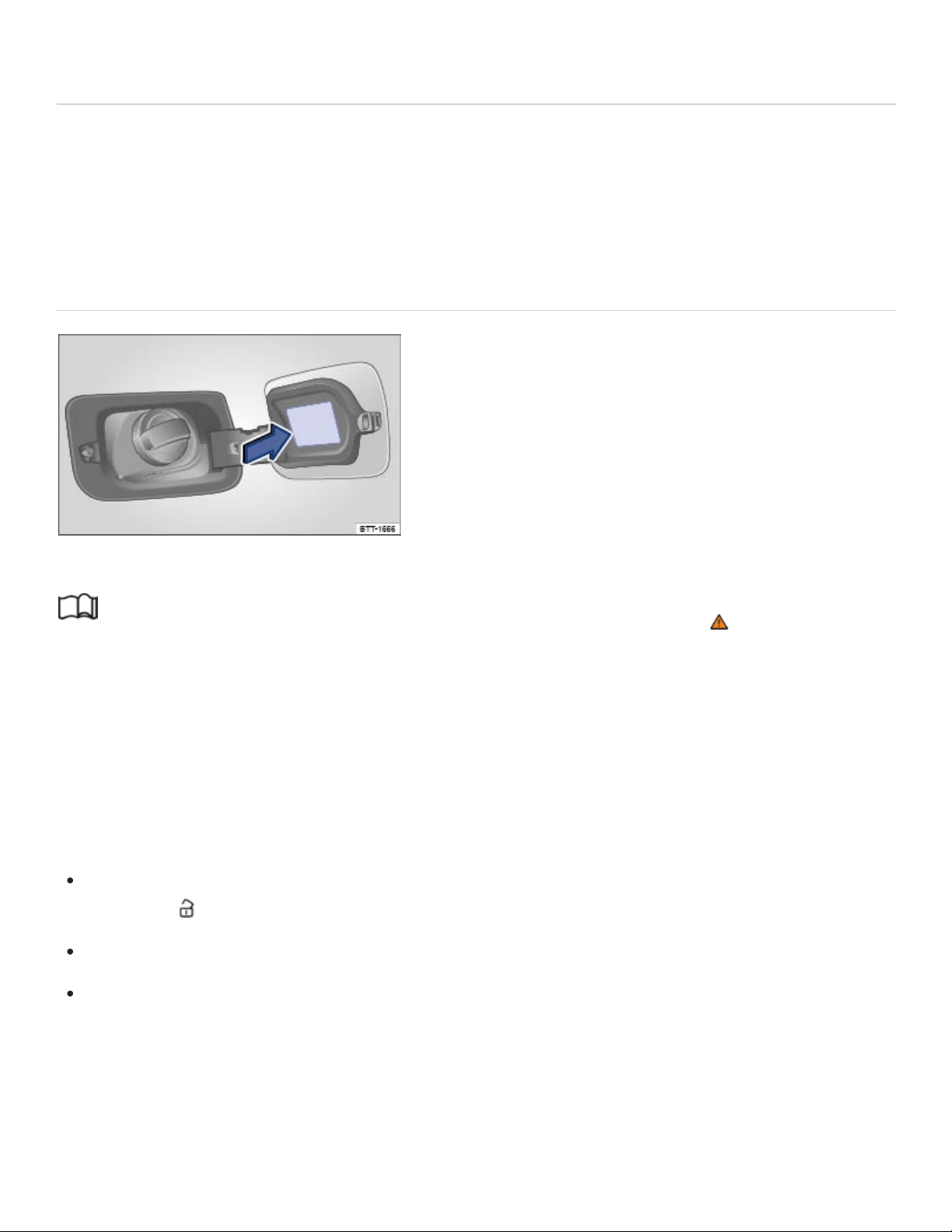
⇒Refueling
The fuel filler flap is on the on the rear passenger side of the vehicle.
The correct fuel grade for your vehicle is listed on a sticker on the inside of the fuel filler flap.
To check your vehicle's fuel capacity, see ⇒Fuel capacities .
Refueling
Fig.164Rear passenger side of vehicle: Fuel cap and open fuel filler flap.
Read and follow the introductory information and safety information first⇒ Introduction to the
subject
Before refueling, always switch off the engine, the ignition, and all mobile phones, and leave them
switched off until refueling is complete.
Opening the fuel filler cap
The fuel filler flap is on the rear passenger side of the vehicle.
Unlock the vehicle from the outside with the vehicle key or press the central locking button in the
driver door to unlock the vehicle from the inside ⇒Doors and power locking system .
Press on the back part of the fuel filler flap and fold open.
Unscrew the fuel cap counterclockwise and remove. Use the slot on the fuel filler flap hinge to
hold the cap while refueling.
Refueling
The correct fuel grade for your vehicle ⇒Fuel types is listed on a sticker on the inside of the fuel filler
flap ⇒Fig.164 (arrow).

The fuel tank is full when the automatic filler nozzle pump switches off the first time ⇒ .
Do not try to add fuel after the pump stops! Topping off the tank in this way may fill the expansion
space that the tank needs and cause fuel to overflow, for example, if it gets warmer outside.
Closing the fuel filler cap
Screw the fuel cap clockwise onto the fuel filler neck until you hear it click into place.
Close the fuel filler flap until you hear it latch shut. The fuel filler flap must be flush with the vehicle
body.
WARNING
Spilled fuel can cause fires, explosions, burns, and other severe injuries.
Always stop refueling once the pump nozzle switches off so that the tank does not overflow.
NOTE
Remove fuel spills from all vehicle surfaces immediately to help prevent damage to the paint,
tires, and wheel housings.
Fuel spills may pollute the environment.
Fuel types
Introduction to the subject
In this chapter you will find information on the following subjects:
⇒Gasoline
⇒Gasoline additives
The correct fuel grade for your engine is shown on a sticker on the inside of the fuel filler flap
⇒Refueling .
Bad or poor quality fuel reduces operating performance, efficiency and service life of the engine. If
you notice any symptoms like rough engine idle or performance, or bucking, or if an indicator light
comes on ⇒Indicator lights and fuel gauge , immediately reduce the vehicle speed, accelerate slowly,

and keep the engine speed in the middle of the rpm range. Avoid high rpm and rapid acceleration. If
these symptoms should appear right after refueling, switch off the engine. In both cases contact an
authorized Volkswagen dealer or an authorized Volkswagen Service Facility to have the engine
checked.
WARNING
Improper refueling or handling of fuel can cause fire, explosion, and severe burns.
Fuel is highly explosive and flammable and can cause severe burns and other injuries.
Heed applicable safety warnings and obey local fuel handling regulations.
Always make sure the fuel cap is screwed on all the way. This keeps fuel from spilling out and
from evaporating.
Failure to shut the engine off while refueling and/or to insert the pump nozzle fully into the
vehicle's filler neck could cause fuel overflow and fuel spray. Fuel spray and overflowing fuel
are dangerous because they can cause fire or serious injury.
For safety reasons, the engine must be turned off when refueling.
Never get back into your vehicle while refueling. If in exceptional circumstances you must get
back in your vehicle while refueling, make certain that you close the door and touch metal to
discharge static electricity before touching the filler nozzle again. Static electricity can cause
sparks that can ignite fuel vapors released during refueling.
Gasoline
Read and follow the introductory information and safety information first⇒ Introduction to the
subject
Octane rating
Octane rating indicates a gasoline's ability to resist engine-damaging “knock” caused by pre-ignition.
Using gasoline that does not meet minimum octane requirements can affect engine performance,
while the use of poor quality gasoline or gasoline with octane levels below 87 can also cause engine
damage. If Regular gasoline is recommended for your engine, you may be able to enhance engine
performance by using Premium gasoline.
The minimum required gasoline octane rating for your engine is listed on a label inside of the fuel filler
flap. This rating may be specified according to AKI (CLC) or RON (ROZ) standards. For this vehicle
the use of premium fuel with 91 AKI is recommended to achieve rated horsepower and torque.

Regardless of whether unleaded Regular or Premium grade gasoline is specified for your vehicle,
Volkswagen recommends using TOP TIER Detergent Gasoline with a minimum octane rating of
87AKI (91RON) for Regular gasoline, and 91AKI (95RON) for Premium gasoline. For more infor‐
mation on TOP TIER Detergent Gasoline, please go to the official website, http://www.toptiergas.com.
The gasoline grades most commonly sold in the United States and Canada have the following octane
ratings, which can usually be found on the filler pump:
Regular grade: 87to 90AKI
Premium grade: 91to 96AKI
Unleaded gasoline
Unleaded gasoline is available throughout the USA and Canada. Volkswagen recommends that you
do not take your vehicle to places where unleaded gasoline may not be available.
Gasoline containing alcohol or MTBE
You may use unleaded gasoline blended with alcohol or MTBE (methyl tertiary butyl ether), commonly
referred to as oxygenated fuels, if the blended mixture meets the following criteria:
Blends of gasoline and methanol (wood alcohol or methyl alcohol):
Anti-Knock Index (AKI) must be 87or higher.
Blend must contain no more than 3% methanol.
Blend must contain more than 2% co-solvents.
Blends of gasoline and ethanol (grain alcohol or ethyl alcohol):
Anti-Knock Index (AKI) must be 87or higher.
Blend must contain no more than 15% ethanol.
Blends of gasoline and MTBE:
Anti-Knock Index (AKI) must be 87or higher.
Blend must contain no more than 15% MTBE.
Seasonally adjusted gasoline

Many fuels are blended especially for winter or summer conditions. When seasons change,
Volkswagen suggests that you buy fuel at busy stations where the seasonal adjustment is more likely
to be made earlier.
WARNING
Starting fluids can explode and cause a run-away vehicle condition.
Never use starting assist fluids.
NOTE
Never use fuel with an octane rating lower than 87AKI/91RON. Using lower octane fuel may
cause expensive engine damage.
Never use leaded gasoline! Leaded gasoline will severely damage your vehicle's catalytic
converter.
Methanol-blended fuels that do not meet the criteria listed above may cause corrosion and
may damage plastic and rubber parts in the fuel system.
Never use fuels that contain lead or other metals (check listing on the fuel pump). Even lead
replacement gasoline (LRP fuels) contain metallic additives in high concentrations. They can
damage the engine.
Do not use fuels that fail to meet the criteria above, or with contents that cannot be identified.
If you cannot tell whether a particular fuel blend meets the criteria above, ask your service sta‐
tion or its fuel supplier. If you notice a loss of fuel economy or drivability and performance
problems using one of these fuel blends, we recommend that you switch to unblended fuel.
Using fuels that are different from those specified above can damage your vehicle's engine
and fuel system and cause performance problems.
Damage to the engine and fuel system and performance problems caused by using fuels that
are different from those specified above or by using starting assist fluids are not the responsi‐
bility of Volkswagen and are not covered under the Emission warranties or any other
Volkswagen Limited Warranty.
Even a single tank full of leaded fuel can do major damage to the catalytic converter and degrade
its effectiveness in reducing polluting emissions.

If you notice a loss of fuel economy or drivability and performance problems using one of these
fuel blends, we recommend that you switch to unblended fuel. Never use fuel line antifreeze of‐
fered for gasoline engines.
Gasoline additives
Read and follow the introductory information and safety information first⇒ Introduction to the
subject
Additives are used to improve the quality of the gasoline.
Fuel quality impacts the operating performance, efficiency and service life of the engine. Therefore,
use high quality gasoline that is already blended by the fuel supplier with suitable gasoline additives
that do not contain metal. The additives provide corrosion protection, clean the fuel system, and help
prevent deposits on the engine.
Volkswagen recommends TOP TIER Detergent Gasoline. For more information on TOP TIER
Detergent Gasoline, please go to the official Web site http://www.toptiergas.com.
If quality gasoline with additives that do not contain metal is not available or engine malfunctions oc‐
cur, you should add the required additives while refueling ⇒ .
Not all gasoline additives are effective. Using the wrong additives can cause significant and expen‐
sive damage to the engine and the catalytic converter. Never use additives that contain metal. Please
note that metal can be included in some aftermarket gasoline additives that are available to be added
to gasoline during or after refueling to help improve knock resistance or increase the octane rating.
Volkswagen recommends using only additives approved by Volkswagen. Appropriate additives as
well as instructions on how to use them are available from your authorized Volkswagen dealer or au‐
thorized Volkswagen Service Facility. Do not add any other gasoline additives.
NOTE
You can damage the engine by using incorrect additives.
Using incorrect gasoline additives can cause extensive engine damage as well as damage to
the catalytic converter.
If you must fuel your vehicle with gasoline whose octane rating is too low, only drive with the
engine speed in the middle of the rpm range and with low engine load. Avoid high rpm and

heavy engine load. Otherwise, the engine could be damaged. Refuel your vehicle with gaso‐
line with the required octane rating as soon as possible.
Do not use fuel that is labeled at the pump as containing metal. Lead replacement fuel con‐
tains high concentrations of metallic additives. Expensive engine and catalytic converter dam‐
age could result.
Fueling your vehicle just one time with leaded fuel or fuel that contains other metallic additives
can affect the performance of the catalytic converter and cause extensive damage to it.
Engine control and emission control system
Introduction to the subject
In this chapter you will find information on the following subjects:
⇒Catalytic converter
⇒Tips and troubleshooting
WARNING
The vehicle exhaust system and the catalytic converter get very hot. This can cause a fire and
serious personal injury.
Never park where parts of the hot exhaust system and catalytic converter could ignite
flammable materials, such as brush, leaves, dry grass, spilled fuel, etc.
Never apply additional undercoating or rustproofing on or near the exhaust manifold, exhaust
pipes, catalytic converter, or heat shields.
WARNING
California Proposition 65Warning
Engine exhaust, some of its constituents, and certain vehicle components contain or emit
chemicals known to the State of California to cause cancer and birth defects and reproductive
harm. In addition, certain fluids contained in vehicles and certain products of component wear
contain or emit chemicals known to the State of California to cause cancer and birth defects
and reproductive harm.

Catalytic converter
Read and follow the introductory information and safety information first⇒ Introduction to the
subject
The catalytic converter provides exhaust gas after-treatment to help reduce pollutants in the exhaust
gas. To help ensure long service life of the exhaust system and gasoline engine catalytic converter:
Only use unleaded fuel ⇒Fuel types .
Never completely empty the fuel tank.
Do not exceed the correct oil level ⇒Engine oil .
Do not tow the vehicle to start it, but use a jump-start instead ⇒Jump-starting .
Tips and troubleshooting
Read and follow the introductory information and safety information first⇒ Introduction to the
subject
When the ignition is switched on, several warning and indicator lights come on briefly for a function
check. They go out after a few seconds.
Exhaust system malfunction
Ease off the accelerator.
Carefully drive to the nearest authorized Volkswagen dealer or authorized Volkswagen Service
Facility to have engine checked.
Engine control/monitoring system misfire
Ease off the accelerator.
Carefully drive to the nearest authorized Volkswagen dealer or authorized Volkswagen Service
Facility to have engine checked.
If the engine misfires or loses power
Reduce speed immediately.
Drive to nearest qualified workshop at medium engine speeds and low engine loads.
If these symptoms occur directly after refuelling, switch off the engine immediately to avoid any
subsequent damage.
Have the vehicle checked by an authorized Volkswagen dealer or authorized Volkswagen Service
Facility.
WARNING
Failure to heed warning lights and instrument cluster text messages can result in a collision and
serious personal injury.
Never ignore warning lights or text WARNINGS.
Always stop the vehicle as soon as it is safe to do so.
NOTE
Failure to heed warning lights or text WARNINGS can result in vehicle damage.
As long as the indicator lights or are on, expect engine malfunctions, increased fuel con‐
sumption, and loss of engine efficiency.
Do it yourself
Vehicle tool kit
Introduction to the subject
In this chapter you will find information on the following subjects:
⇒Storage
⇒Contents
When securing the vehicle after a breakdown, always obey all applicable legal requirements.
WARNING
Loose tools and other items in the vehicle tool kit and a loose compact spare wheel may be
thrown through the passenger compartment if you brake suddenly or steer sharply or are in‐
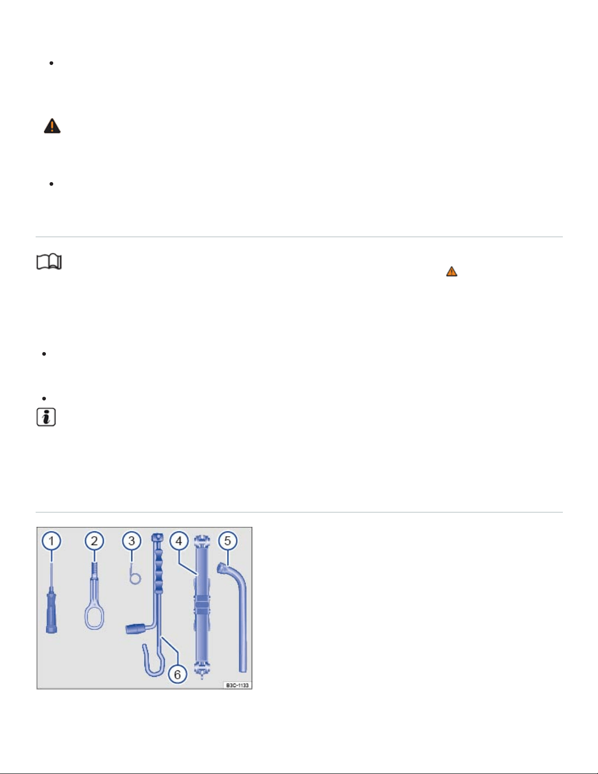
volved in an accident. This can cause severe injuries.
Always make sure the vehicle tool kit and compact spare wheel are securely stowed in the lug‐
gage compartment.
WARNING
Improper or damaged vehicle tools can lead to accidents and injury.
Never work with tools that are damaged or not right for the job.
Storage
Read and follow the introductory information and safety information first⇒ Introduction to the
subject
The vehicle tool kit may be in one of several places in the luggage compartment.
In a bag in a side storage compartment on the left or right side of the luggage compartment.
Rotate the quick-release fasteners 90° to open the storage compartment.
In a foam container under the luggage compartment floor.
Completely retract the jack after use. Otherwise it will not fit in its compartment and cannot be
stowed safely.
Contents
Fig.165Contents of the vehicle tool kit.
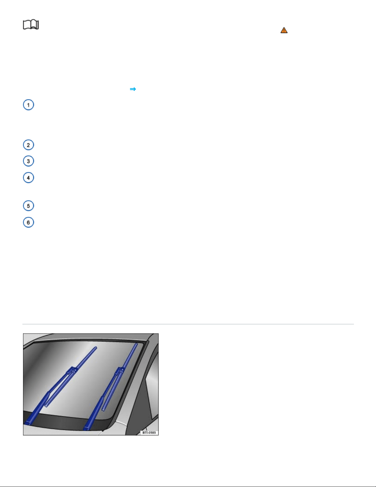
Read and follow the introductory information and safety information first⇒ Introduction to the
subject
The contents of the vehicle tool kit depend on the vehicle's equipment. The following describes the
maximum contents.
Contents of the vehicle tool kit⇒Fig.165
Screwdriver with a hexagonal socket in the handle for removing or inserting previously loosened
wheel bolts. The screwdriver blade is reversible. The handle for the screwdriver may be stored in the
end of the lug wrench handle.
Screw-in towing eye.
Hubcap puller clip for removing hubcaps, full wheel covers, or wheel bolt caps.
Jack. Before putting the jack back in the tool kit, be sure to completely crank the jack down to its
original position.
Lug wrench.
Crank.
Maintaining the vehicle jack
The vehicle jack requires no regular maintenance. If necessary, apply multi-purpose grease to the
joints of the vehicle jack.
Windshield wiper blades
Windshield wiper service position
Fig.166Windshield wiper in service position.
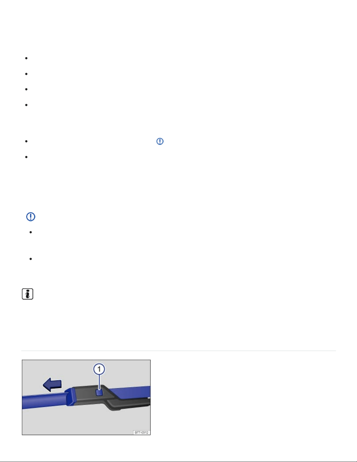
In the service position, the wiper arms can be lifted away from the windshield ⇒Fig.166 . Move the
wipers to the service position as follows:
The engine hood must be closed ⇒In the engine compartment .
Switch the ignition off, turn it on briefly, and then off again.
Press the windshield wiper lever down briefly when the ignition is off.
Wipers move into service position.
Lifting the wiper blades and tilting them away from the windshield
Put the wiper arms in service position ⇒ .
Do not handle the wiper blades, handle the wiper arms only at the attachment above the wiper
blades.
Carefully fold the wiper arms back onto the windshield before driving! Switch the ignition on and press
the windshield wiper lever down briefly. The wiper arms move back to their original position.
NOTE
To help prevent damage to the engine hood and the windshield wiper arms, lift the wiper arms
away from the windshield only when they are in the service position.
Always carefully fold the windshield wiper arms down against the windshield before driving the
vehicle.
The windshield wiper arms can be moved to the service position only when the vehicle is not
moving.
Cleaning and changing the windshield wiper blades
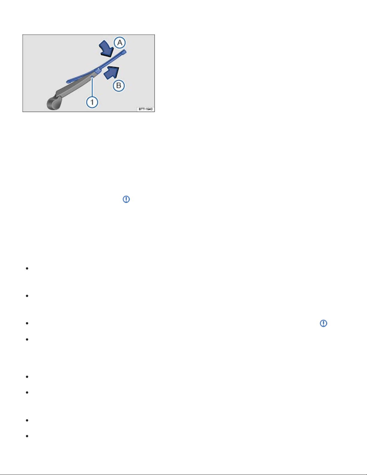
Fig.167Changing the windshield wiper blades.
Fig.168Changing the rear window wiper blades.
Factory-installed wiper blades have a graphite coating. The graphite coating helps the wiper blades
glide smoothly over the windshield. If this coating is worn or damaged, the wipers may grab or
squeak.
Check all wiper blades regularly. Wiper blades that grab and squeak must be replaced if worn or
damaged and cleaned if dirty ⇒ .
Replace worn or damaged wiper blades immediately. Replacement blades may be purchased from
any authorized Volkswagen dealer or authorized Volkswagen Service Facility.
Cleaning the wiper blades
Move the front wiper arms to the service position and lift them away from the windshield
⇒Windshield wiper service position .
Do not handle the wiper blades; handle the wiper arms only at the attachment above the wiper
blades.
If the blades are very dirty, carefully clean the wiper blades with a damp sponge or cloth ⇒ .
Carefully fold the wiper arm back down onto the windshield.
Changing the front windshield wiper blades
Move the front wiper arms to the service position ⇒Windshield wiper service position .
Lift the wiper arms away from the windshield. Do not handle the wiper blades; handle the wiper
arms only at the attachment above the wiper blades.
Press and hold the release button ⇒Fig.167① .
While lifting the wiper blade in the direction of the wiper arm, pull off the wiper blade in the direc‐
tion of the arrow. This may require moderate force.

Install a new wiper blade of same length and type onto the wiper arm by pushing in the opposite
direction of the arrow until it latches.
Carefully fold the wiper arm back down onto the windshield.
Changing the rear window wiper blade
Lift the wiper arm away from the rear window.
Do not handle the wiper blades, handle the wiper arms only at the attachment above the wiper
blades.
Press and hold the release button ⇒Fig.168① .
While lifting the wiper blade in the direction of the wiper arm ⇒Fig.168 (arrow
Ⓐ
), pull off the
wiper blade in the direction of the arrow
Ⓑ
. This may require moderate force.
Install a new wiper blade of the same length and type onto the wiper arm by pushing in the op‐
posite direction of the arrow⇒Fig.168
Ⓑ
until it latches.
Carefully fold the wiper arm back down onto the window.
WARNING
Worn or dirty wiper blades reduce visibility and increase the risk of accidents and severe injuries.
Always change wiper blades if they are damaged or worn, and if they cannot clean the win‐
dows sufficiently.
NOTE
Damaged or dirty wiper blades can scratch the windshield and the rear window.
Solvents, abrasive sponges and sharp-edged objects will damage the graphite coating on the
wiper blades.
Do not clean the windows with gasoline, nail polish remover, paint thinner or similar fluids.
To help prevent damage to the engine hood and the windshield wiper arms, lift the wiper arms
away from the windshield only when they are in the service position.
Automatic car washes and vehicle care products can leave a wax residue on all glass surfaces,
which can cause the windshield wipers to grab and squeak. Remove these wax residues with a
special cleaner or cleaning clothes.

Replacing light bulbs
Introduction to the subject
In this chapter you will find information on the following subjects:
⇒Tips and troubleshooting
Changing a light bulb requires a certain amount of skill. Therefore, Volkswagen recommends having
the light bulb changed by an authorized Volkswagen dealer or an authorized Volkswagen Service
Facility. Special training and knowledge are generally required when other vehicle parts must be dis‐
assembled to replace a bulb.
You should always keep a box in the vehicle with all the replacement bulbs required for traffic safety.
Replacement bulbs are available from your authorized Volkswagen dealer or authorized Volkswagen
Service Facility. The laws of some countries explicitly require you to have replacement bulbs in the
vehicle.
Driving with outside lights that do not work may be against the law.
Additional light bulb specifications
Some factory-installed light bulbs in the headlights or the rear lights may have different specifications
than conventional light bulbs. Specifications are on the glass bulb or on the metal base.
LED vehicle lights
Owners cannot replace LED lights themselves. If some LEDs fail, this may be an indication that more
elements are on the point of failure. If this happens, have the lights checked and replaced if neces‐
sary at a qualified workshop.
Headlights
Daytime running lights
Turn signals
License plate light
WARNING

Crashes and other accidents can happen when you cannot see the road ahead and when you
cannot be seen by other motorists.
WARNING
Improper replacement of burned out headlights and other light bulbs can cause serious personal
injury.
Stop! Always read and heed the WARNINGS before doing any work in the engine compart‐
ment ⇒In the engine compartment . The engine compartment of any motor vehicle is a poten‐
tially dangerous area, and work in this area can lead to serious personal injury.
HID – High Intensity Discharge (Xenon) headlights get power from a high voltage source that
can cause severe personal injury and even death if handled improperly.
H7bulbs and HID – High Intensity Discharge (Xenon) headlights are under high pressure and
can explode if handled improperly.
Always let a burned out light bulb cool down before replacing it.
Never replace a light bulb unless you are familiar with all of the necessary procedures. In par‐
ticular, never remove a headlight unless you know exactly how to carry out the job and have
the correct tools and light bulbs.
If you are uncertain about what to do, have the work performed by an authorized Volkswagen
dealer, an authorized Volkswagen Service Facility, or another qualified workshop. Serious per‐
sonal injury may result from improperly performed work.
We strongly recommend that you always have HID – High Intensity Discharge (Xenon) head‐
lights and H7bulbs replaced by a qualified technician.
Do not touch the glass of light bulbs with your bare hands. Fingerprints left on the bulb evapo‐
rate due to the heat when the bulb is switched on and cause the reflector to cloud.
There are sharp edges on and around the headlight housing in the engine compartment and
the rear light housing. Wear hand protection if you replace bulbs.
NOTE
After replacing a headlight bulb or other light bulb, always make sure that the rubber covers or
plastic caps have been properly and securely reinstalled to help prevent water from getting into
the electrical connections and the headlight housing and damaging the electrical system.

Individual LEDs cannot be replaced. Contact your authorized Volkswagen dealer or authorized
Volkswagen Service Facility for assistance.
Tips and troubleshooting
Read and follow the introductory information and safety information first⇒ Introduction to the
subject
When the ignition is switched on, several warning and indicator lights come on briefly for a function
check. They go out after a few seconds.
An exterior light is not working properly
If the indicator light comes on, at least one of the exterior vehicle lights is not working.
See an authorized Volkswagen dealer, an authorized Volkswagen Service Facility, or other quali‐
fied workshop to replace the light that isn't working.
A trailer turn signal or the entire trailer lighting system is not working.
Replace the burnt out light bulb or check the trailer lighting system.
WARNING
Failure to heed warning lights and instrument cluster text messages can result in a collision and
serious personal injury.
Never ignore warning lights or text WARNINGS.
Always stop the vehicle as soon as it is safe to do so.
Failure of a single LED within a taillight is not indicated. However, the indicator light will light
up if all LEDs fail.
Replacing fuses
Introduction to the subject

In this chapter you will find information on the following subjects:
⇒Fuses in the instrument panel
⇒Fuses in the engine compartment
⇒Replacing blown fuses
Due to ongoing development of the vehicle, configuration-dependent allocation of fuses and the com‐
bined fuse protection of multiple loads with one fuse, an up-to-date overview of the fuse location per
load is not possible at the time of printing. Detailed information regarding fuse box layout is available
from authorized Volkswagen dealers and authorized Volkswagen Service Facilities.
In general, one fuse can protect several loads. One load can also be protected by several fuses.
Find out why the fuse blew and correct the problem before replacing a blown fuse. If a newly replaced
fuse blows again after a short time, the electrical system should be checked by an authorized
Volkswagen dealer or an authorized Volkswagen Service Facility.
WARNING
High voltage systems in the engine compartment can cause electrical shocks, severe burns, and
even death!
Never touch ignition cables. Never touch other components of the high voltage electronic igni‐
tion system.
Avoid short circuits in the electrical system.
WARNING
Using the wrong fuse, using a blown fuse that has been repaired, and using metal objects in
place of fuses to complete the electrical connection in the circuit can cause fires and serious per‐
sonal injury.
Never replace a fuse with one that has a higher amp rating. Replace a blown fuse only with a
fuse of the same amperage (same color and same imprint) and same overall size.
Never repair fuses.
Never replace fuses with a metal strip, a paper clip, or a similar object.

NOTE
To help prevent damage to the electrical system, switch off all lights and accessories, switch
off the ignition, and remove the key from the ignition switch (if applicable) before replacing a
fuse.
If a fuse is replaced with a fuse with higher amperage, this can also cause damage at different
locations in the electrical system.
Open fuse boxes must be protected from dirt and moisture. Dirt and moisture in fuse boxes
can cause damage to the electrical system.
NOTE
To help prevent vehicle damage, be careful when removing fuse box covers and be sure to re‐
install them properly.
Open fuse boxes must be protected from dirt and moisture. Dirt and moisture in fuse boxes
can cause damage to the electrical system.
The vehicle contains other fuses in addition to those mentioned in this section. Have these fuses
replaced by an authorized Volkswagen dealer or an authorized Volkswagen Service Facility.
Fuses in the instrument panel
Fig.169On the driver side in the instrument panel: Removing the storage compartment to access the
fuses.
Read and follow the introductory information and safety information first⇒ Introduction to the
subject

Accessing fuses in the instrument panel
Open the storage compartment next to the steering wheel and remove any contents.
With one hand, press the rubber release ① tab up at the top of the storage compartment to re‐
lease the fuse box cover. The cover should open easily.
With the other hand, pull the cover straight out.
To install, fit the cover on the hinges at the bottom of the opening. Guide the cover into the instru‐
ment panel by pushing in the direction opposite of the arrow until it latches into place ⇒Fig.169 .
Fuses in the engine compartment
Fig.170In the engine compartment: Fuse box cover ① with tweezers ②.
Read and follow the introductory information and safety information first⇒ Introduction to the
subject
Opening the fuse box in the engine compartment
Open the engine hood ⇒In the engine compartment .
Press the release tabs in the direction of the arrows ⇒Fig.170 to unlock the fuse box cover ①.
Remove the cover upward.
To install push the cover onto the fuse box. The locking tabs must latch with an audible click.
In some vehicles, there are plastic tweezers for removing fuses on the inside of the fuse box cover
⇒Fig.170② .
Replacing blown fuses
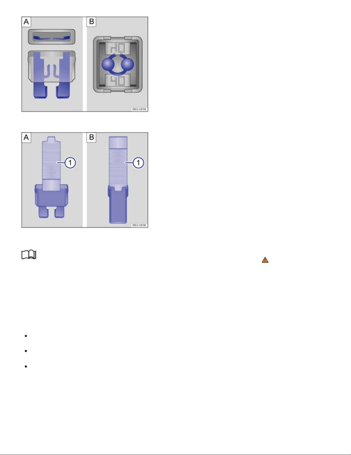
Color
Black
Purple
Fig.171Blown fuse: :Blade fuse. :JCASE® fuse.
Fig.172Removing or installing a blade fuse with the plastic tweezers: :Blade fuse. :JCASE® fuse.
Read and follow the introductory information and safety information first⇒ Introduction to the
subject
Replace a blown fuse only with a fuse of the same amperage (same color and same imprint) and
same overall size.
Fuse types
Regular blade fuse (ATO ).
Mini blade fuse (MINI ).
Cartridge fuse (JCASE ).
Fuse color coding (ATO/MINI)
Amp rating
1amp
3amps
®
®
®

Orange
Brown
Red
Blue
Yellow
White or clear
Green
Light green
Blue
Pink
Green
Red
Yellow
5amps
7.5amps
10amps
15amps
20amps
25amps
30amps
40amps
Fuse color coding (JCASE)
20amps
30amps
40amps
50amps
60amps
Preparations
Switch off the headlights, the ignition, and all electrical consumers.
Open the appropriate fuse box ⇒Fuses in the instrument panel , ⇒Fuses in the engine compart‐
ment .
Identifying a blown fuse
For blade fuses (ATO , MINI ): Remove the fuse and shine a flashlight on it. This makes it easier
to tell if the fuse has blown. A blown blade fuse has metal strips that have burned through, which
you can see through the transparent housing from above and from the side ⇒Fig.171 .
For cartridge fuses (JCASE ): Shine a flashlight on the fuse. This makes it easier to tell if the fuse
has blown. A blown cartridge fuse has metal strips that have burned through, which you can see
through the transparent housing from above ⇒Fig.171 .
Replacing a fuse
In some vehicles, there are plastic tweezers for removing blade fuses on the inside of the fuse box
cover in the engine compartment.
® ®
®

Open the fuse box cover in the engine compartment ⇒Fuses in the instrument panel and remove
the plastic tweezers.
Depending on the type of fuse, slide the tweezers ⇒Fig.172 ① or ⇒Fig.172 ① onto the
fuse from the side.
Pull out the fuse.
If the fuse is blown, replace the fuse with a new fuse of the same amperage (same color and
same imprint) and same size ⇒ .
Clip the plastic tweezers back into the holder inside the fuse box cover.
Replace the fuse box cover.
NOTE
If a fuse is replaced with a fuse with higher amperage, damage can occur at various places in the
electrical system.
Jump-starting
Introduction to the subject
In this chapter you will find information on the following subjects:
⇒Jump-start terminal
⇒Using jumper cables
If your engine does not start because the vehicle battery is dead, your vehicle's battery can be con‐
nected to the battery of another vehicle to start your engine (jump-starting). Check the battery acid
level indicator on the vehicle battery before jump-starting ⇒Vehicle battery .
You must use jumper cables that meet recognized industrial standards (check information provided by
the jumper cable manufacturer). For vehicles with gasoline engines, the cross-section of the jumper
cable wire must be at least 0.038in. (25mm ), or about 3ga. (AWG).
Location of the vehicle battery
The 12Volt vehicle battery is in the engine compartment.
WARNING
2 2

Working on the batteries or the electrical system in your vehicle can cause serious acid burns,
fires, or electrical shock.
Always keep children away from battery acid and vehicle batteries in general.
Sulfuric battery acid is very corrosive and can cause blindness and damage to unprotected
skin. Never let battery acid or lead particles contact your eyes, skin, and clothing.
Never lean over a vehicle battery. Always wear protective gloves and eye protection. To re‐
duce your risk of injury, never tilt the batteries; acid could spill out through the vents and burn
you.
A highly explosive mixture of gases is given off when the battery is being charged.
Always avoid fires, sparks, open flame, and smoking. Never create sparks or electrostatic
charges when handling cables and electrical equipment. Never short-circuit the battery termi‐
nals. High-energy sparks can cause serious personal injury.
If you get battery acid in your eyes or on your skin, immediately rinse with cold water for sev‐
eral minutes and get medical attention immediately. If you swallow any battery acid, get medi‐
cal attention immediately.
WARNING
Improper use of jumper cables when jump-starting a vehicle with a dead battery can cause the
battery to explode, leading to serious personal injury. To help reduce the risk of battery explosion:
All work on the batteries or the electrical system in your vehicle can cause serious acid burns,
fires, or electrical shocks. Always read and heed the following WARNINGS and safety precau‐
tions before working on the batteries or the electrical system ⇒Vehicle battery .
Always make sure that the battery providing starting assistance (the booster battery) has the
same voltage as the dead battery (12V) and about the same amperage capacity (see battery
label).
Never jump-start a vehicle with a thawed or frozen vehicle battery. The battery can explode. A
dead battery can freeze at temperatures around +32°F (0°C).
A battery that is frozen or was frozen, but has since thawed, must be replaced.
When the vehicle battery is jump-started, it gives off hydrogen gas, which is highly explosive!
Always keep fire, sparks, open flame, and smoking materials far away from vehicle batteries.
Never use a mobile telephone while connecting or disconnecting jumper cables.

Jump-start batteries only in well-ventilated areas. Batteries give off highly explosive hydrogen
gas during jump-starting.
Always route the jumper cables so that they cannot get caught in any moving parts in the en‐
gine compartment.
Never short out the battery terminals by connecting the positive(+) and negative(-) terminals
with each other.
Never connect the negative cable from the other vehicle directly to the negative terminal of the
dead battery, as this may cause the hydrogen gas given off by the dead battery to explode.
Never attach the negative cable from the vehicle providing starting assistance to any part of
the fuel system or to the brake hoses or brake lines.
Never allow the non-insulated parts of the battery clamps to touch.
Never allow the jumper cable attached to the positive battery terminal to contact metal parts of
the vehicle.
Always follow the instructions of the jumper cable manufacturer.
NOTE
To help prevent extensive damage to the vehicle electrical system, read and heed the following:
Connecting jumper cables improperly can cause a short circuit and do expensive damage to
the vehicle's electrical system.
Do not let the vehicles touch each other while the jumper cables are connected. If they do,
electrical current may flow between the vehicles when the positive(+) terminals are con‐
nected, causing electrical system damage.
Jump-start terminal
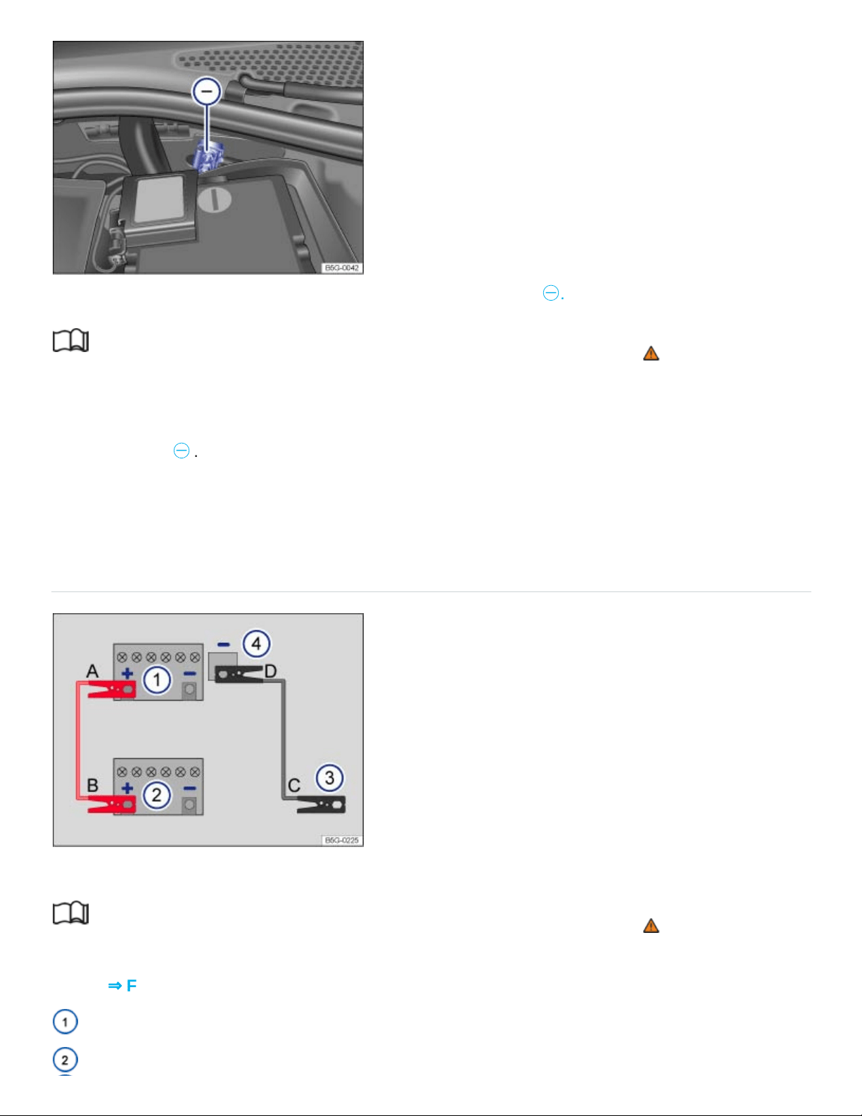
Fig.173In the engine compartment: Negative jump-start terminal
㊀
.
Read and follow the introductory information and safety information first⇒ Introduction to the
subject
The jump-start terminal for connecting the black (negative) jump-start cable is in the engine compart‐
ment ⇒Fig.173
㊀
.
Your vehicle can only be jump-started or be used to jump-start another vehicle via this jump-start
terminal.
Using jumper cables
Fig.174Diagram for attaching the jumper cables: Dead battery ① and booster battery ②.
Read and follow the introductory information and safety information first⇒ Introduction to the
subject
Key to ⇒Fig.174 :
Battery of the vehicle receiving starting assistance.
Battery of the vehicle providing starting assistance.

Negative jump-start terminal on vehicle providing starting assistance.
Negative jump-start terminal on vehicle receiving starting assistance.
The dead battery must be properly connected to the vehicle's electrical system.
Make certain that the vehicles are not touching each other. Otherwise, electric current could flow as
soon as the positive battery terminals (+) are connected. Use longer jumper cables if necessary.
The clamps on the jumper cables must have good contact to bare metal on the battery terminals.
If the engine does not start, stop the process after 10seconds and repeat after about 1minute. If the
engine still does not start, get professional assistance.
The procedure for attaching and for removing the jumper cables is described below. Perform each of
the following steps only in the order described, which follow the letters shown in the illustration
⇒Fig.174 A–B–C–D.
Checklist
Switch off the ignition in both vehicles Starting and stopping the engine.
Open the battery cover, if necessary Vehicle battery.
Attach one end of the red jumper cable A to the positive battery terminal ⊕ on the dead bat‐
tery: ① .
Attach the other end of the red jumper cable B to the positive battery terminal ⊕ on the good
battery (booster battery): ②.
Attach one end of the black jumper cable C to the negative jump-start terminal of the vehicle
providing assistance: ③, or if that is not available, to a bare metal part of the vehicle providing as‐
sistance. This part should be connected directly to the engine block.
Attach the other end of the black jumper cable D to the negative jump-start terminal of the ve‐
hicle receiving assistance ④ ,or if that is not available, to a bare metal part of the vehicle receiving
assistance. This part should be connected directly to the engine block. Attach the clamp to a point
that is as far away as possible from the dead battery①
Route the jumper cables so that they cannot get caught in any moving parts in the engine
compartment of either vehicle.
Starting the engine

Start the engine of the vehicle with the good battery that is providing help and let it run at idle
speed.
Turn on the ignition of the vehicle with the dead battery. If the engine starts, wait 2to 3minutes
until it runs smoothly before removing the jumper cables as described below ⇒ . If the engine
does not start within about 10seconds, turn off the ignition and wait at least 1minute; then try
again. If the engine still does not start, get professional assistance.
Before removing the jumper cables
Switch off the headlights (if they are on).
In the vehicle with the dead battery, switch on the heater fan and the rear window defroster. This
helps to minimize voltage spikes when the cables are disconnected.
Checklist
With the engine running, remove the jumper cables in reverse order to the way they were
connected.
Disconnect the black (-) cable from the vehicle with the dead battery.
Disconnect the black (-) cable from the other vehicle (vehicle with the good battery).
Disconnect the red (+) cable from the other vehicle (vehicle with the good battery).
Disconnect the red (+) cable from the vehicle with the dead battery.
Close the battery cover.
WARNING
Improper use of jumper cables when jump-starting a vehicle with a dead battery can cause the
battery to explode, leading to serious personal injury. To help reduce the risk of battery explosion:
All work on the batteries or the electrical system in your vehicle can cause serious acid burns,
fires, or electrical shocks. Always read and heed the following WARNINGS and safety precau‐
tions before working on the batteries or the electrical system ⇒Vehicle battery .
Always wear proper eye protection. Never lean over the vehicle battery.
Attach the jumper cables in the correct order: first the positive cable, then the negative cable.
Never connect the negative cable from the vehicle providing starting assistance to parts of the
fuel system or to the brake hoses or brake lines.
Never allow the non-insulated parts of the battery clamps to touch.

Never allow the jumper cable attached to the positive battery terminal to contact metal parts of
the vehicle.
Check the battery acid level indicator window on the vehicle battery. Use a flashlight, never a
match, cigarette lighter, or other open flame. If you cannot see the color of the window clearly,
or if it is light yellow or colorless, do not jump-start the vehicle. Get expert assistance.
Avoid electrostatic discharge in the vicinity of the vehicle battery. Sparks may cause the hydro‐
gen gas escaping from the vehicle battery to ignite.
Never jump-start a vehicle with a battery that is damaged or frozen or that was frozen and has
thawed. The battery can explode. Replace the battery instead.
Always follow the instructions of the jumper cable manufacturer.
Always make sure that the battery providing starting assistance has the same voltage as the
dead battery (12V) and about the same capacity (see battery label).
Batteries give off explosive hydrogen gas. Always keep fire, sparks, open flame and smoking
materials away from batteries.
Never connect the negative cable from the other vehicle directly to the negative battery termi‐
nal on the dead battery. The hydrogen gas from the battery is explosive.
Never short out the battery terminals by connecting the positive (+) and negative (-) terminals
with each other.
Towing
Introduction to the subject
In this chapter you will find information on the following subjects:
⇒Towing on a commercial tow truck
⇒Tips on towing
⇒Installing the rear towing eye
⇒Driving tips while towing
Observe legal requirements when towing.

Your vehicle may be equipped with a trailer package.
For technical reasons:
A vehicle with a dead battery must never be towed. Jump-start the vehicle instead.
It is not possible to tow-start or push-start your vehicle⇒ . Jump-start the vehicle
instead.
Vehicles with Keyless Access may only be towed with the ignition on.
Towing the vehicle when the engine is turned off and the ignition is turned on drains the vehicle bat‐
tery. Depending on the charge level of the vehicle battery, it is possible that even after just a few min‐
utes, electrical devices such as the emergency flashers may not have the power necessary to func‐
tion. The steering wheel might lock in vehicles with Keyless Access ⇒ .
WARNING
Never tow a vehicle without any electrical power.
Never remove the key from the ignition switch or turn off the ignition with the starter button
while the vehicle is moving or rolling to a stop. The electronic steering column could suddenly
lock, you would not be able to steer, and you could lose control of the vehicle, crash, and seri‐
ously injure yourself and others.
If the vehicle loses power while it is being towed, stop towing the vehicle immediately and con‐
tact your authorized Volkswagen dealer or authorized Volkswagen Service Facility for
assistance.
WARNING
Towing a vehicle changes the way it handles and brakes. To help reduce the risk of an accident
and serious personal injury, note the following:
The driver of the vehicle that is being towed:
Since the brake booster also does not work when the engine is stopped, you will need to
press harder on the brake pedal to slow down or stop. Always be alert so as not to rear-
end the towing vehicle.
Will have to use considerably more force to turn the steering wheel because the power
steering is not working.

The driver of the vehicle that is doing the towing:
Must accelerate gradually and gently and avoid jerking movements.
Must not brake hard or steer sharply.
Must brake earlier and more gently than in normal driving.
NOTE
Be careful not to damage the paint when installing and removing the towing eye and the cover
for the threaded hole behind the bumper.
NOTE
Never tow-start or push-start your vehicle; if you do, unburned fuel can get into the catalytic con‐
verter and damage it. Jump-start the vehicle instead.
Towing on a commercial tow truck
Read and follow the introductory information and safety information first⇒ Introduction to the
subject
To help avoid damaging the vehicle, have it towed only by a professional towing company. Read and
heed the following information:
General information
Never let the vehicle be towed at speeds above 30mph (50km/h).
Never let the vehicle be towed for more than 30miles (50km).
Towing automatic transmission vehicles
Release the parking brake.
Shift the transmission into Neutral(N).
Tow the vehicle only with its front wheels off the ground ⇒ .
Special towing instructions for vehicles with all-wheel drive (4MOTION)

To help prevent unnecessary damage, vehicles with all-wheel drive (4MOTION) must be trans‐
ported on a flatbed truck.
To load the vehicle on the flatbed, use the towing eye found in the vehicle tool kit ⇒Vehicle tool
kit , ⇒Installing the rear towing eye .
When not to tow your vehicle
If there is little or no oil in the transmission because of damage to your vehicle, it must be moved with
the drive wheels off the ground. The vehicle can only be towed if its ignition is switched on and its
electrical system is operating.
In the following situations, the vehicle cannot be towed at all and must be transported on a flatbed
truck or trailer:
If the front and rear wheels cannot turn.
If the vehicle battery is dead (because the electronic parking brake and the electronic steering col‐
umn lock cannot be released, if engaged).
If you have to tow an automatic transmission vehicle more than 30miles (50km).
If the steering or the wheel clearance might be impaired, for example, after an accident.
WARNING
It is not safe for children or other persons to ride in a vehicle that is being towed.
Never let children or anyone else stay in the vehicle while it is being towed.
NOTE
The drive axle rotates while the vehicle is being towed with its rear wheels off the ground. This
can damage the automatic transmission.
Never tow automatic transmission vehicle with the rear wheels off the ground.
Tips on towing
Read and follow the introductory information and safety information first⇒ Introduction to the
subject
Towing eye, tow rope or tow bar

A towing eye is included in your vehicle's tool kit. This can be inserted in a threaded hole in the rear
bumper, so you can tow other vehicles. Vehicles with a trailer hitch preparation do not have a
threaded hole in the rear bumper for the towing eye, even if there is a cover for one. Towing a vehicle
with a tow bar is safer and easier on both vehicles than using a tow rope. A tow rope should be used
only if a tow bar is not available.
The tow rope should be flexible enough to help protect both vehicles from damage. Use a synthetic
fiber rope or similar rope.
Attach the tow rope or tow bar only to the towing eye included in the vehicle tool kit for this purpose,
or to a trailer hitch.
For vehicles with a factory-installed trailer hitch: Only use a towing bar designed for installing on a
trailer hitch ⇒Trailer towing .
Towing automatic transmission vehicles
Check whether your vehicle can be towed at all; see below ⇒When not to tow your vehicle .
If yes, note the following for the towed vehicle:
Put the transmission in Neutral(N).
Do not tow faster than 30mph (50km/h).
Do not tow more than 30miles (50km).
When a commercial tow truck is being used, the vehicle must only be towed with the front wheels
lifted off the ground.
Follow the special instructions for towing vehicles with all-wheel drive (4MOTION).
Towing vehicles with all-wheel drive (4MOTION)
Vehicles with all-wheel drive (4MOTION) must be transported on a flatbed truck or trailer. Otherwise
the powertrain may be damaged.
When not to tow your vehicle
In the following situations, the vehicle cannot be towed and must be transported on a flatbed truck
or trailer:
If transmission fluid has leaked out of the transmission.
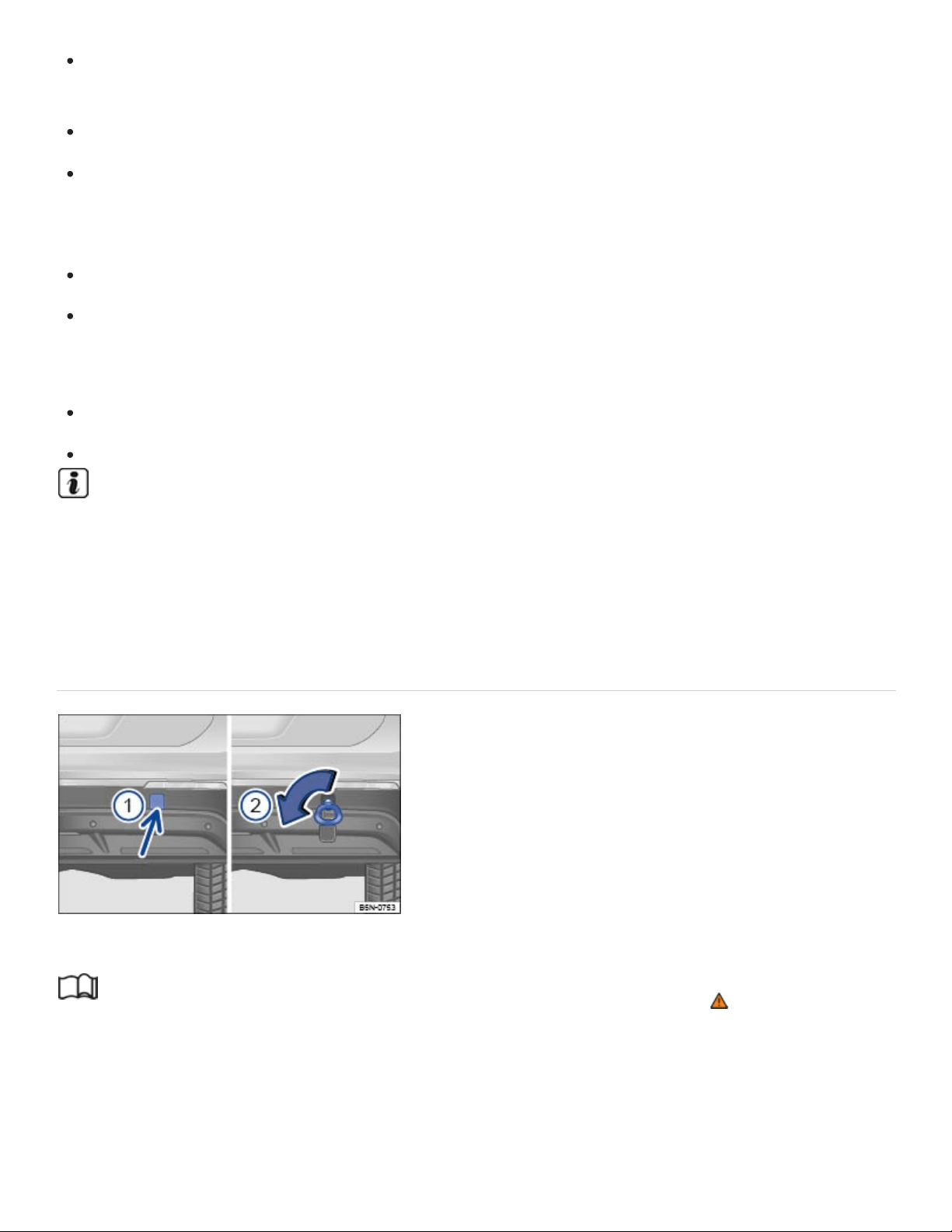
If there is little or no oil in the transmission because of damage to your vehicle, it must be moved
with the drive wheels off the ground.
If the front and rear wheels cannot turn.
If the vehicle battery is dead (because the electronic steering column lock engages and cannot be
released). If the electronic parking brake was engaged when the battery died, it cannot be
released.
If you have to tow an automatic transmission vehicle more than 30miles (50km).
If the steering or the wheel clearance might be impaired, for example, after an accident.
Towing other vehicles
Obey all legal requirements.
Read and heed all towing information in the owner's manual for the other vehicle.
A vehicle can be towed only if the electronic parking brake and the electronic steering column
lock are released. In case of a power loss or malfunctions of the electrical system, the engine
may have to be jump-started ⇒Jump-starting in order to release the electronic parking brake
and the electronic steering column lock.
Installing the rear towing eye
Fig.175In the right rear bumper: Installing the towing eye.
Read and follow the introductory information and safety information first⇒ Introduction to the
subject
Depending on equipment, there is a threaded hole for the towing eye in the right rear bumper behind
a cover ⇒Fig.175① .

For vehicles with a factory-installed trailer hitch: There is no threaded hole behind the cover. Use the
trailer hitch for towing.
Always keep the towing eye in the vehicle and stow it securely.
Read and follow the notes about towing ⇒Tips on towing .
Installing the rear towing eye
Take the towing eye and the lug wrench out of the vehicle tool kit in the luggage compartment
⇒Vehicle tool kit .
Push on the cover at the bottom (arrow) so that it pops out ⇒Fig.175① .
Remove the cover and let it hang from the bumper.
Screw the towing eye counterclockwise into the threaded hole as far as it will go ⇒Fig.175② ⇒
. Use the lug wrench to turn and tighten the towing eye.
When towing is complete, unscrew the towing eye clockwise to remove it.
Position the lower lip of the cover in the opening in the bumper and carefully push the upper lip
over the edge of the opening until the cover locks in place.
NOTE
Always make sure the towing eye is screwed all the way into the threaded hole so that it is se‐
cure. If not, it could be pulled out while your vehicle is being towed.
Vehicles with a factory-installed trailer hitch may use only tow bars that are specially designed
for fitting on the ball mount. If you use an unsuitable tow bar, the ball mount and the vehicle
could be damaged. You should use a tow rope instead.
Driving tips while towing
Read and follow the introductory information and safety information first⇒ Introduction to the
subject
Towing requires some experience, especially when using a tow rope. Both drivers must be familiar
with the techniques required for towing. Inexperienced drivers should not try to tow a vehicle or to
drive a vehicle that is being towed.

Do not pull too hard with the towing vehicle, and avoid jerking the tow rope. When towing on an un‐
paved road, there is always a risk of overloading and damaging the attachment points.
If your vehicle is being towed, it can still signal turns even if the emergency flashers are switched on,
as long as the ignition is switched on. Use the turn signal in the normal way. The emergency flashers
go off as long as the turn signal is blinking. As soon as the turn signal lever returns to its neutral posi‐
tion, the emergency flashers are automatically switched on again.
As the driver of the vehicle being towed:
If your vehicle is the one being towed, the ignition must be switched on to keep the steering wheel
from locking. Also make sure that the turn signals, horn, windshield wipers, and windshield wash‐
ers work properly.
Since power steering does not work when the engine is switched off, more effort is needed to
steer the vehicle.
Since the brake booster also does not work when the engine is stopped, you will need to press
harder on the brake pedal to slow down or stop. Do not hit the towing vehicle.
Read and heed the information and WARNINGS in the towing vehicle's owner's manual.
As the driver of the towing vehicle:
Drive especially carefully and accelerate gently. Avoid sudden driving maneuvers.
Brake earlier and more gently than usual and with light pedal pressure.
Read and heed the information and WARNINGS in the owner's manual of the vehicle being
towed.
Checking and refilling
In the engine compartment
Introduction to the subject
In this chapter you will find information on the following subjects:
⇒Preparing to work in the engine compartment
⇒Opening or closing the engine compartment

⇒Display
Always position the vehicle on a firm and level surface before doing any work in the engine
compartment.
The engine compartment of a vehicle is a hazardous area. Never do any work on the engine or in the
engine compartment unless you:
know exactly how to carry out the job,
have the correct technical information and the proper tools and supplies, and
are familiar with the necessary safety precautions ⇒ .
If you are uncertain in any way, have the work done by an authorized Volkswagen dealer or an autho‐
rized Volkswagen Service Facility. Serious personal injury may result from improperly performed
work.
WARNING
Unintended vehicle movement during maintenance work can cause serious personal injuries.
Never work under the vehicle unless you have safely secured the vehicle from moving. If you
must work under the vehicle with the wheels on the ground, always make sure that the vehicle
is on level ground, that all 4wheels are chocked to keep them from moving, and that the key is
not in the ignition.
If you must work under a vehicle raised on a floor jack, always make sure that the vehicle is
safely supported on safety stands intended for that purpose that are strong enough to support
the weight of the vehicle. The jack supplied with the vehicle is not strong enough for this pur‐
pose and can collapse causing serious personal injury.
Start-stop must be deactivated.
WARNING
The engine compartment of any motor vehicle is a potentially dangerous area and can cause se‐
rious personal injury.
Always use extreme caution when doing any work in the engine compartment. Always follow
commonly accepted safety practices and use common sense. Never risk personal injury.

Never perform any work in the engine compartment unless you know exactly how to carry out
the job and have the correct technical information and the correct tools.
If you are uncertain about what to do, have the work performed by an authorized Volkswagen
dealer, an authorized Volkswagen Service Facility, or another qualified workshop. Serious per‐
sonal injury may result from improperly performed work.
Never open or close the engine hood if steam or coolant is escaping. Hot steam or coolant can
cause serious burns. Always wait until you no longer see or hear steam or coolant escaping
from the engine.
Always let the engine cool down completely before carefully opening the hood.
Hot parts of the engine and the exhaust system will burn skin on contact.
When the engine has cooled down and you are ready to open the hood:
Firmly apply the parking brake and shift the transmission into Park (P).
Take the vehicle key out of the ignition.
On vehicles with Keyless Access, make sure that the remote control vehicle key is out of
range of the vehicle and that the vehicle cannot be started by depressing the starter but‐
ton ⇒Starter button .
Always keep children and others away from the engine compartment and never leave
them unsupervised.
The engine coolant system is under pressure when the engine is hot. Never unscrew the
coolant expansion tank cap when the engine is hot. Hot coolant can spray out and cause se‐
vere burns and other serious injuries.
Turn the cap slowly and very carefully in a counterclockwise direction while applying light
downward pressure on the top of the cap.
Always protect your face, hands, and arms from hot escaping coolant or steam by cover‐
ing the cap with a large, thick rag.
Never spill fluids on the engine or exhaust system when refilling. Spilling fluids onto hot parts
of the engine or exhaust system can cause a fire.
WARNING

High voltage systems in the engine compartment can cause electrical shocks or even electrocu‐
tion, severe burns, other serious injuries, and even death!
Never short-circuit the electrical system. Be especially careful when using jumper cables. The
vehicle's battery could explode!
To reduce the risk of electrical shock and personal injury while the engine is running or being
started:
Never touch ignition cables. Never touch other components of the high voltage electronic
ignition system.
Read and heed the important information and warnings on cleaning the engine compartment
⇒Engine compartment and plenum chamber .
WARNING
Moving parts in the engine compartment can cause serious personal injury on contact.
Never reach into the area around or touch the radiator fan. Contact with the blades can cause
serious personal injury. Always remember that the radiator fan is temperature-controlled and
can come on suddenly even when the engine has been switched off for a while and the key
has been removed from the ignition.
If you have to perform a check or repair when the engine is running, there are more risks from
the rotating parts, such as the drive belts, alternator, radiator fan, etc., and from the high-volt‐
age ignition system. Always use extreme care.
Always make sure that jewelry, loose clothing and long hair do not get caught in rotating
engine parts. Before starting any work remove your jewelry, take off your necktie, tie
back and cover your hair, and do not wear clothing that can hang down and get caught in
moving engine parts.
Always use extreme caution if the accelerator pedal has to be depressed to perform a
check. The vehicle will start to move even if the parking brake is on.
Never leave any objects in the engine compartment, for example cleaning rags and tools.
Objects left behind can cause malfunctions, engine damage, and even fires.
WARNING

Additional materials in the engine compartment such as blankets can interfere with the operation
of the engine and can cause fires, which can lead to serious injuries.
Never cover the engine with blankets or other materials.
WARNING
Operating fluids and some materials in the engine compartment can catch fire easily, causing
burns and other serious personal injuries!
Never smoke near the engine compartment.
Never work next to open flames or sparks.
Never pour or spill operating fluids or other flammable liquids on the engine. These fluids can
ignite on hot engine parts and cause injuries.
Before working on the vehicle's 12 Volt electrical system:
Always disconnect the 12Volt vehicle battery. Note that if the vehicle is locked when the
12 Volt vehicle battery is disconnected, the anti-theft alarm system will sound ⇒Anti-theft
alarm system .
Never work near a furnace, water heater, or other open flames.
Always have a functional, approved fire extinguisher nearby.
NOTE
When changing or topping off fluids, make sure that you pour the fluids into the correct reservoirs.
Adding the wrong type of operating fluids will cause serious malfunctions and engine damage.
Fluid leaks and spills are harmful to the environment. Regularly check the ground underneath
your vehicle for this reason. If you find spots of oil or other fluids, have your vehicle checked by
your authorized Volkswagen dealer or authorized Volkswagen Service Facility. Dispose of leaked
operating fluids properly.
Preparing to work in the engine compartment
Read and follow the introductory information and safety information first⇒ Introduction to the
subject

Checklist
Before any work in the engine compartment, carry out the following steps in the order in
which they are listed ⇒ :
Park the vehicle in a safe place on a firm, level surface.
Hold the brake pedal down until the engine is switched off.
Shift the transmission into Park (P) Automatic transmission.
Set the parking brake to help prevent the vehicle from moving Electronic parking brake.
Stop the engine and remove the key from the ignition switch or turn off the ignition with the
starter button and remove the key from the vehicle Starting and stopping the engine.
Let the engine cool down sufficiently.
Keep children and others away from the vehicle.
Make sure the vehicle cannot move unexpectedly.
WARNING
Disregarding the safety-related checklist may result in serious injuries.
Always review and follow the checklist. Follow accepted safety practices and use common
sense.
Opening or closing the engine compartment
Fig.176In the footwell on the driver side: Inside engine hood release lever.
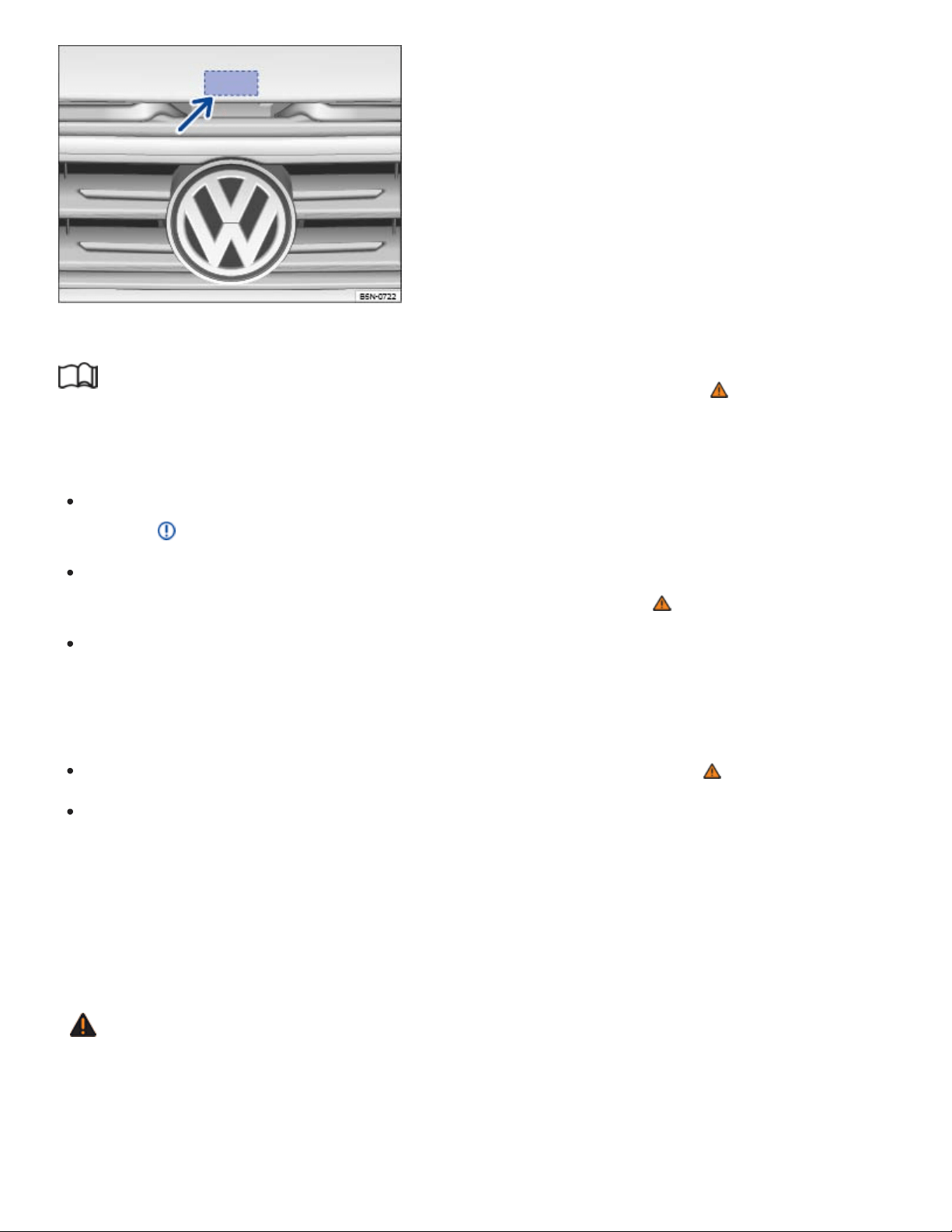
Fig.177Above the radiator grille: Outside engine hood release.
Read and follow the introductory information and safety information first⇒ Introduction to the
subject
Opening the engine hood
Before you open the hood, make sure that the windshield wiper arms are resting on the wind‐
shield ⇒ .
Open the driver door and pull the inside hood release lever in the direction of the arrow
⇒Fig.176 . The engine hood is released from its latch by a spring ⇒ .
Push the outside hood release lever ⇒Fig.177 (arrow) and lift the hood all the way up. A gas-
pressure strut will hold the hood up.
Closing the engine hood
Pull the hood down to overcome the resistance of the gas-pressure strut ⇒ .
Lower the engine hood by hand until it is about 8in. (20cm) above its latch and then let it drop
into place to latch it. Do not push down on it afterwards!
If the hood does not close completely, open it again and close it properly.
When the hood is properly closed, you can see that it fits flush with the other body parts. The display
in the instrument cluster no longer indicates that the engine hood is open ⇒Displays .
WARNING
If the hood is not closed properly, it could fly up and block your view while you are driving. This
can lead to a crash and serious personal injuries.
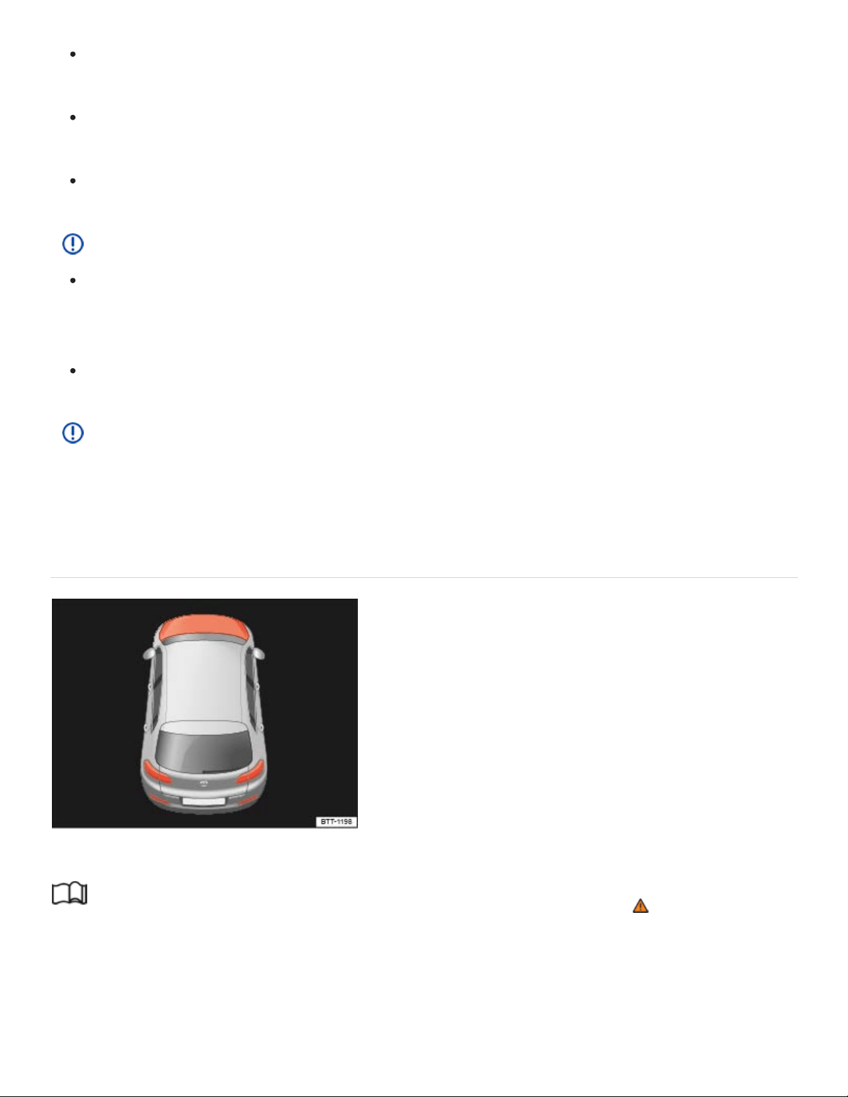
After closing the engine hood, check that the hood release lever is properly latched into the
hood latch. The engine hood must be flush with the surrounding auto body parts.
If you ever notice that the hood latch is not properly secured when the vehicle is moving, stop
at once and close it.
Never let anyone get in the way of the hood when closing it.
NOTE
Make sure the windshield wipers are switched off and the windshield wiper arms are resting on
the windshield before you open the hood. Otherwise, the windshield wipers and the hood may
be damaged.
Always put the windshield wiper arms down against the windshield before driving the vehicle.
NOTE
Before opening or closing the engine hood, make sure there is enough room to do so, for exam‐
ple when the vehicle is in a garage.
Display
Fig.178In the instrument cluster display: Engine hood open or not properly closed.
Read and follow the introductory information and safety information first⇒ Introduction to the
subject
When the ignition is switched on, several warning and indicator lights come on briefly for a function
check. They go out after a few seconds.

If the engine hood is not closed properly, the vehicle icon appears in the instrument cluster display in‐
dicating the engine hood is open ⇒Fig.178 . Stop! Open and close the engine hood again.
The icon may still be displayed even after the ignition is switched off. The instrument cluster display
goes out a short time after the vehicle has been locked.
WARNING
Failure to heed warning lights and instrument cluster text messages can result in a collision and
serious personal injury.
Never ignore warning lights or text WARNINGS.
Always stop the vehicle as soon as it is safe to do so.
Operating fluids and equipment
Operating fluids and parts that wear out with use (such as timing belts, tires, engine coolants, en‐
gine oils, spark plugs, and vehicle batteries) are constantly being improved. For this reason, it is im‐
portant to have operating fluids changed and wearing parts replaced by an authorized Volkswagen
dealer or authorized Volkswagen Service Facility. Authorized Volkswagen dealers and authorized
Volkswagen Service Facilities are always up-to-date regarding new developments and changes.
WARNING
Improper use of operating fluids and equipment can cause accidents, serious personal injuries,
burns and/or poisoning.
Always store vehicle care products in a safe place in original containers that are securely
closed.
To reduce the risk of poisoning, never use empty food or beverage containers that might mis‐
lead someone into drinking from them.
Always keep vehicle care products out of the reach of children.
Always read and heed all the instructions and all WARNINGS on the package before using ve‐
hicle care products.
When using products that give off harmful fumes, always work outdoors or in a well ventilated
area.
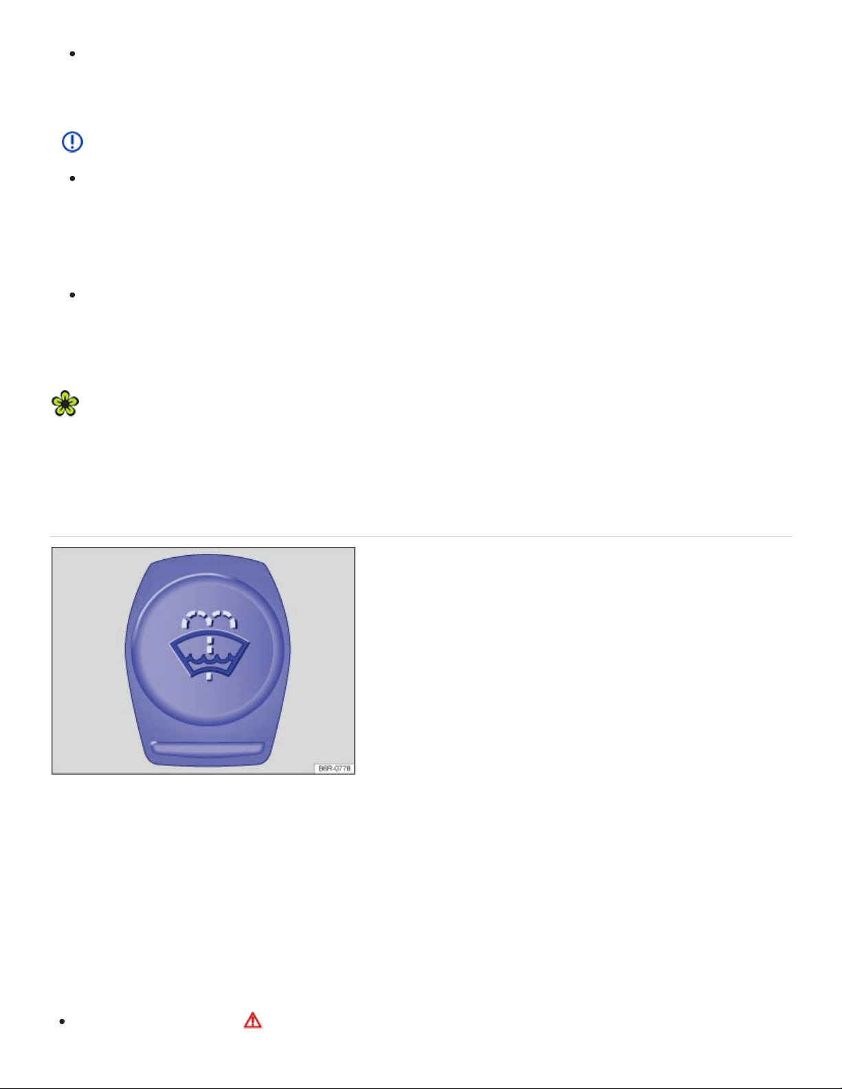
Never use fuel, turpentine, engine oil, nail polish remover or other volatile fluids for vehicle
care. They are poisonous and highly flammable. They could cause fires and explosions!
NOTE
Only refill with suitable operating fluids. When changing or topping off fluids, make sure that
you pour the fluids into the correct reservoirs. Adding incorrect fluids will cause serious mal‐
functions and engine damage! Under no circumstances should you mix up operating fluids.
Otherwise serious malfunctions and engine damage can occur!
Accessories and other things installed in front of the cooling air intakes impair the efficiency of
the engine coolant. The engine can overheat under high outside temperatures or under high
engine loads!
Leaking operating fluids can pollute the environment. Collect leaking operating fluids in suitable
containers and dispose of them properly in accordance with applicable environmental laws and
regulations.
Windshield washer fluid
Fig.179In the engine compartment: Cap of the windshield washer fluid reservoir
Check the windshield washer fluid level regularly and refill as necessary.
There is a filter screen in the filler neck of the windshield washer fluid reservoir. The screen helps to
keep large particles and debris from getting into and clogging the windshield washer nozzles when
adding windshield washer fluid. Take the screen out only to clean it. If the screen is damaged or miss‐
ing, have it replaced immediately, otherwise the system may become clogged and not work properly.
Open the engine hood ⇒Preparing to work in the engine compartment .

The windshield washer fluid reservoir can be identified by the symbol on its cap ⇒Fig.179 .
Check if there is still enough windshield washer fluid in the reservoir.
Refill with clear water (not distilled water) and an appropriate windshield washer fluid that is rec‐
ommended by Volkswagen ⇒ . Follow the directions on the container.
In cold weather, always use a special windshield washer antifreeze solution that will help keep the
water from freezing ⇒ .
Recommended cleaners
For the warmer months, Windscreen Clear Summer- G052184A1 - or equivalent. Mixing ratio
1:100 (1part concentrate to 100parts water) in the windshield washer reservoir.
All-season Windscreen Clear- G052164A2 - or equivalent. Mixing ratio in winter to 0°F (-18°C)
about 1:2 (1part concentrate to 2parts water), otherwise, mixing ratio 1:4in the windshield
washer reservoir.
Filling capacity
The windshield washer fluid reservoir holds about 3.2–7.9quarts (3–7.5liters).
WARNING
Never mix antifreeze or similar additives into the windshield washer reservoir. This could produce
an oily film on the windshield, which would considerably reduce visibility.
Use clear water (not distilled water) with a cleaning solution recommended by Volkswagen.
If necessary, blend with a suitable windshield washer fluid antifreeze agent.
NOTE
Never mix cleaning solutions recommended by Volkswagen with other cleaning agents. If you
do, this could cause sediments or other by-products that can clog the windshield washer
nozzles.
When refilling, do not confuse one type of operating liquid with another! Otherwise serious
malfunctions and engine damage can occur!
Engine oil
Introduction to the subject

In this chapter you will find information on the following subjects:
⇒Engine oil specifications
⇒Changing engine oil
⇒Engine oil consumption
⇒Checking the engine oil level and adding oil
⇒Warning and indicator lights
WARNING
Improper handling of engine oil can cause severe burns and other serious injuries.
Always wear eye protection.
Engine oil is poisonous and must be stored out of the reach of children.
Store engine oil only in the closed original container. This also applies to used oil until
disposal.
To reduce the risk of poisoning, never drain the oil into empty food or beverage containers that
might mislead someone into drinking from them.
Continuous contact with used engine oil is harmful to your skin. Always protect your skin by
washing thoroughly with soap and water.
Engine oil becomes extremely hot when the engine is running and can cause severe burns.
Always let the engine cool down to the touch.
Like all other operating fluids, engine oil can pollute the environment. Collect leaked or spilled op‐
erating fluids and dispose of them properly in accordance with applicable environmental laws and
regulations.
Engine oil specifications
Read and follow the introductory information and safety information first⇒ Introduction to the
subject

The engine oil used must conform to exact specifications.
Using the proper engine oil is important for the functionality and service life of the engine. Your engine
was factory-filled with a high-quality multi-grade oil which can usually be used throughout the entire
year.
Engine oils are constantly being improved. Authorized Volkswagen dealers and authorized
Volkswagen Service Facilities are always up-to-date regarding new developments and changes.
Volkswagen therefore recommends that you have the engine oil changed by an authorized
Volkswagen dealer or an authorized Volkswagen Service Facility.
Engine oil quality is based not only on requirements for engines and exhaust treatment systems, but
also on fuel quality. Engine oil comes into contact with fuel and fuel residue in all internal combustion
engines, causing engine oil to age and its lubricating qualities to deteriorate.
Your engine was factory-filled with an all-season engine oil that meets strict Volkswagen oil quality
standards and has a viscosity grade of SAE0W-30. You can use this oil for normal driving in all
temperatures.
Always use an approved oil that expressly complies with the Volkswagen oil quality standard that ap‐
plies to your vehicle's engine.
Approved engine oil
Engines
Engine oil
specification
Gasoline engines VW50200
At the time this Manual was printed, the engine oils available in the U.S. that meet these Volkswagen
standards are “synthetic” oils. This does not mean, however, that any “synthetic” engine oil will meet
Volkswagen standards. Always use an approved oil that expressly complies with the Volkswagen oil
quality standard that applies to your vehicle's engine.
If VW 502 00 is not available, you may also use an engine oil that meets the specification VW 504 00.
General recommendations:

If engine oil that meets the applicable Volkswagen oil quality standard with viscosity grade SAE0W-
30 is not available in your area, be sure to use a viscosity grade suitable for the climate, season, and
operating conditions that exist where the vehicle is used. Make sure the oil meets the quality standard
listed in . If none is available that meets this engine oil specification, see the information in ⇒ .
Engine oil capacities
Engines Engine oil capacity (with filter)
280hp (206kW), 3.6L gasoline engines About 5.8quarts (5.5liters)
238 hp (175 kW), 2.0 L gasoline engines About 4.9 quarts (4.7 liters)
NOTE
If you need to add oil and there is none available that meets the Volkswagen oil quality standard
your engine requires, you may add a total of no more than 1/2quart (0.5liter) of an engine oil
that meets ACEAA3/B4 or API SN (API SM) specifications and has a viscosity grade of SAE 0W-
30.
OR: if there is no oil available that has a viscosity grade of SAE0W-30, you may add a total of
no more than 1/2quart (0.5liter) of an engine oil that meets the oil quality standard VW50200
or VW50400 and has a viscosity grade of SAE5W-40 or SAE5W-30.
Using oil with a viscosity grade other than SAE0W-30 may cause vehicle emissions and
fuel consumption to increase slightly. Only use other oils in case of emergency!
Use only an engine oil that expressly complies with the Volkswagen oil quality standard speci‐
fied for your vehicle's engine. Using any other oil can cause serious engine damage that will
not be covered by any Volkswagen Limited Warranty.
Do not mix any lubricants or other additives into the engine oil. Doing so can cause engine
damage! Damage caused by these kinds of additives are not covered by any Volkswagen
Limited Warranty.
Changing engine oil
Read and follow the introductory information and safety information first⇒ Introduction to the
subject

The engine oil must be changed according to the intervals specified in your ⇒BookletWarranty and
Maintenance,.
Changing oil at regular intervals is very important because the lubricating properties of oil decrease
gradually during normal vehicle use. If you are not sure when to have the oil changed, ask your au‐
thorized Volkswagen dealer or authorized Volkswagen Service Facility.
Sometimes, engine oil should be changed more often than specified for normal use. Change oil more
frequently if you often drive short distances, in dusty areas or in stop-and-go traffic, or if you use your
vehicle where temperatures stay below freezing for long periods.
Volkswagen recommends that you have your oil and oil filter changed by an authorized Volkswagen
dealer or an authorized Volkswagen Service Facility ⇒ . They have the required expertise and spe‐
cial tools and will dispose of the old oil properly.
Detergent additives in the oil will make fresh oil look dark after the engine has been running a short
time. This is normal and no reason to change engine oil more often.
WARNING
If you must change the engine oil yourself, be sure to take the following precautions:
Always wear eye protection.
To reduce the risk of burns from hot engine oil, let the engine cool down completely before
beginning.
When removing the oil drain plug with your fingers, stay as far away as possible. Always keep
your forearm parallel to the ground to help prevent hot oil from running down your arm.
Drain the oil into a container designed for this purpose, one large enough to hold at least the
total amount of oil in your engine.
To reduce the risk of poisoning, never drain the oil into empty food or beverage containers that
might mislead someone into drinking from them.
Always use an oil that has been specifically approved for your vehicle ⇒Engine oil specifica‐
tions
Engine oil is poisonous and must be stored out of the reach of children.
Continuous contact with used engine oil is harmful to your skin. Always protect your skin by
washing thoroughly with soap and water.

Before changing the oil, first make sure you know where you can properly dispose of the old oil.
Dispose of the old oil in an environmentally-responsible manner. Never dump the old oil on gar‐
den soil, in wooded areas, in the street, into streams, rivers, or bodies of water, or down sewage
drains.
Engine oil consumption
Read and follow the introductory information and safety information first⇒ Introduction to the
subject
To provide effective lubrication and cooling for internal engine parts, all internal combustion engines
use some oil. Oil consumption varies from engine to engine and may change over the life of the en‐
gine. Engines tend to use more oil during the break-in period than they do afterward, when oil con‐
sumption has stabilized.
Under normal conditions, the rate of oil consumption depends on oil quality as well as viscosity, en‐
gine speed (rpm), outside temperature, road conditions, the amount of oil dilution caused by con‐
densed water or fuel residue, and oxidation of the oil. Oil consumption may increase with engine wear
over time, until replacement of worn engine parts may become necessary.
Volkswagen recommends that you to check the engine oil level at regular intervals, preferably every
time you fill the fuel tank, and always before a long trip. Your vehicle may consume engine oil de‐
pending on several variables. A maximum of 1quart per 1200miles (1liter per 2000km) would be
considered normal. New vehicles may consume more oil over the first 3000miles (5000km).
The oil pressure warning light is not an indicator of low engine oil level. If the warning light
stays on or flashes while driving (above 1500rpm), a chime will sound. It indicates that the oil
pressure is too low. Stop the engine in a safe place immediately, check the engine oil level and
add oil if necessary. If the engine oil level is normal, but the light continues to flash, do not
keep driving or let the engine idle, as damage may occur.
If you believe your engine uses too much oil, we recommend that you consult your authorized
Volkswagen dealer or authorized Volkswagen Service Facility so that the cause of your concern can
be properly diagnosed. Please keep in mind that accurate measurement of oil consumption requires
great care and may take some time. Your authorized Volkswagen dealer and authorized Volkswagen
Service Facility have instructions for how to measure oil consumption accurately.
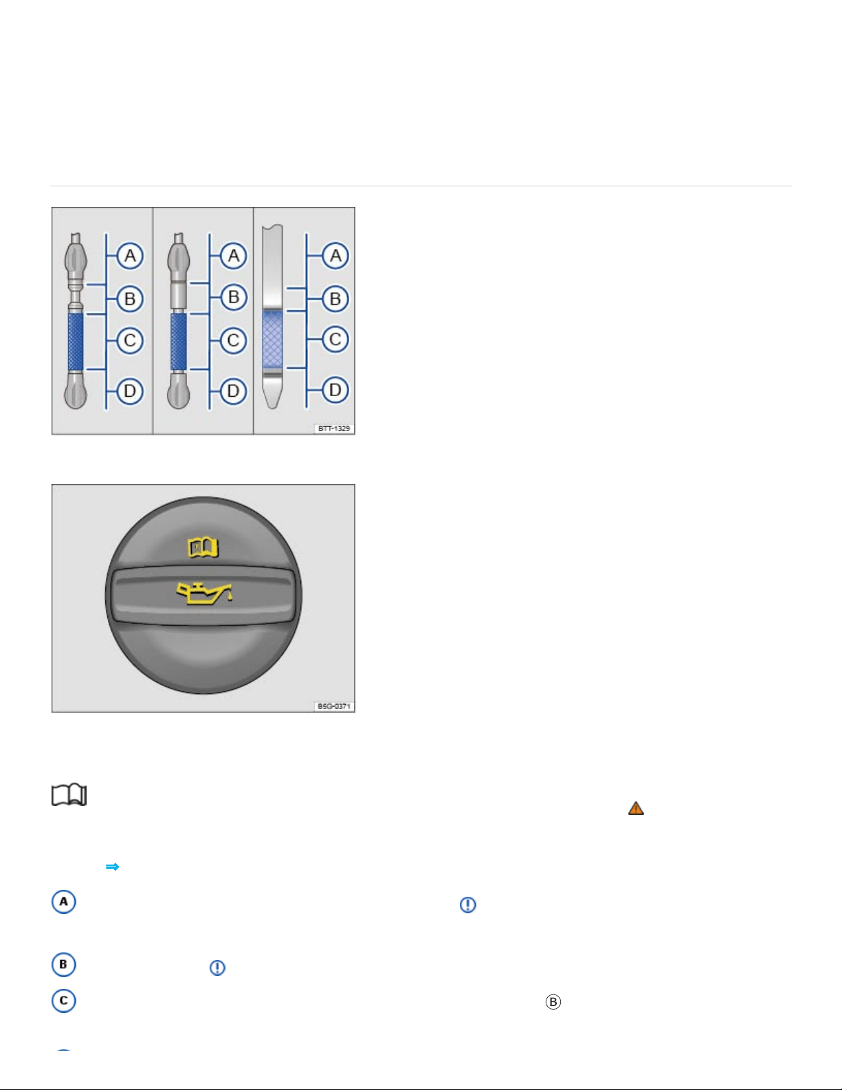
Depending on the way the vehicle is driven and the operating conditions, oil consumption can be
up to 1quart per 1200miles (1liter per 2000km). Consumption may be higher for new vehicles
during the first 3000miles (5000km).
Checking the engine oil level and adding oil
Fig.180Engine oil dipstick with oil level marks.
Fig.181In the engine compartment: Engine oil filler cap (cap design may vary depending on vehicle
equipment).
Read and follow the introductory information and safety information first⇒ Introduction to the
subject
Key to ⇒Fig.180 :
Engine oil level too high. Do not start the engine⇒ . Contact an authorized Volkswagen
dealer or an authorized Volkswagen Service Facility for assistance.
Do not refill oil ⇒ .
You may add oil, as long as the oil level does not go above the
Ⓑ
range.

Engine oil level too low. You must add oil (about 1quart / 1.0liter). After adding oil, make sure
that the oil level is about in the middle of the
Ⓒ
range.
Checklist
Perform the steps in the order listed ⇒ :
With the engine at operating temperature, park the vehicle on a level surface to help prevent
an incorrect oil level reading.
Switch off the engine and wait a few minutes for the engine oil to flow back into the oil pan.
Open the engine hood Preparing to work in the engine compartment.
Find the oil filler opening and the dipstick. You can identify these by the symbol on the engine
oil filler cap and the colored handle on the dipstick. If you are not sure where the cap and the dip‐
stick are located, see your authorized Volkswagen dealer or authorized Volkswagen Service Facility
for assistance.
Remove the dipstick from the guide tube and wipe the dipstick off using a clean cloth.
Reinsert the dipstick into the guide tube and push it all the way in. If there is an alignment tab
on the top of the engine oil dipstick, make sure it lines up with the notch in the guide tube, and that
the dipstick goes all the way in.
Remove the dipstick again and read the oil level on the dipstick as described below:
Ⓐ
: Engine
oil level too high. Do not start the engine . Contact an authorized Volkswagen dealer or an autho‐
rized Volkswagen Service Facility for assistance.
Ⓑ
: Do not add any oil . Continue with step 15.
Ⓒ
: Oil may be added, depending on the oil level. Continue with step 8 or step 15.
Ⓓ
: You must
add oil (about 1quart / 1.0liter). Continue with step 8.
After reading the oil level, reinsert the dipstick back into the guide tube and push it all the way
in.
Remove the cap on the engine oil filler opening .
Only add engine oil that Volkswagen has approved for that engine Engine oil specifications.
Add the oil gradually in small quantities (no more than 1pint / 0.5liter).
To help prevent overfilling, you must wait about 1minute each time you add oil so that the oil
can flow into the oil pan up to the marking on the dipstick.
Read the oil level on the dipstick again before adding another small amount, if necessary.
Never add too much oil .

After adding oil, the level must at least be in the center of the
Ⓒ
range and can enter range
Ⓑ
,
but should never enter range
Ⓐ
.
After adding oil, securely install the cap on the engine oil filler opening. Otherwise, oil could
leak out while the engine is running.
Insert the oil dipstick back in the guide tube and push it all the way in.
Close the hood .
WARNING
Engine oil can ignite when it touches hot engine parts. This can cause fires, burns, and other se‐
vere injuries.
Never spill oil on the engine. Oil spilled on a cold engine can also cause a fire when the engine
warms up.
Always make certain that you screw the cap of the engine oil filler opening back on tightly after
adding oil and that the dipstick has been pushed all the way back into the in the guide tube.
This helps prevent engine oil from leaking onto the hot engine when the engine is running.
NOTE
Do not start the engine if the engine oil level is in range ⇒Fig.180
Ⓐ
. Contact an authorized
Volkswagen dealer or an authorized Volkswagen Service Facility. Otherwise the catalytic con‐
verter and engine can be damaged!
When changing or topping off fluids, make sure that you pour the fluids into the correct reser‐
voirs. Adding the wrong type of operating fluids will cause serious malfunctions and engine
damage.
The engine oil level should never be in range ⇒Fig.180
Ⓐ
. Otherwise oil can be drawn in by the
crankcase ventilation system and enter the atmosphere via the exhaust system.
Warning and indicator lights
Read and follow the introductory information and safety information first⇒ Introduction to the
subject

When the ignition is switched on, several warning and indicator lights come on briefly for a function
check. They go out after a few seconds.
Depending on equipment, the engine oil temperature may be displayed in the Volkswagen
Information System Driving data menu ⇒Volkswagen Information System .
Engine oil pressure too low
The red indicator light flashes.
Stop!
Switch off the engine.
Check the engine oil level ⇒Checking the engine oil level and adding oil .
If the warning light flashes although the oil level is normal, do not continue driving or let the engine
idle. Otherwise, the engine could be damaged.
Contact an authorized Volkswagen dealer or an authorized Volkswagen Service Facility.
Engine oil level too low
The yellow indicator light comes on.
Stop!
Switch off the engine.
Check the engine oil level ⇒Checking the engine oil level and adding oil .
If necessary, contact an authorized Volkswagen dealer or an authorized Volkswagen Service
Facility for assistance.
Engine oil system malfunction
The yellow indicator light flashes.
Have the engine oil sensor checked by an authorized Volkswagen dealer or an authorized
Volkswagen Service Facility.
WARNING
Failure to heed warning lights and instrument cluster text messages can result in a collision and
serious personal injury.

Never ignore warning lights or text WARNINGS.
Always stop the vehicle as soon as it is safe to do so.
Engine coolant
Introduction to the subject
In this chapter you will find information on the following subjects:
⇒Warning light and engine coolant temperature gauge
⇒Engine coolant specifications
⇒Checking engine coolant level and topping off
Never do any work on the coolant system unless you
know exactly how to carry out the job,
have the correct technical information and the proper tools, supplies, and operating fluids, and
are familiar with the necessary safety precautions ⇒ !
If you are uncertain in any way, have the work done by an authorized Volkswagen dealer or an autho‐
rized Volkswagen Service Facility.
Serious personal injury may result from improperly performed work.
WARNING
Engine coolant is poisonous!
Always keep the coolant in its original container stored in a safe place.
To reduce the risk of poisoning, never store engine coolant in empty food or beverage contain‐
ers or in any other containers that might mislead someone into drinking from them.
Always keep engine coolant out of reach of children.
Always make sure there is enough of the correct coolant additive to provide proper antifreeze
protection at the coldest temperatures that can be expected where the vehicle will be used.
At extremely cold temperatures, the coolant could freeze, causing the vehicle to break down.
The heater would also not work, and vehicle occupants could be without protection at sub‐

freezing temperatures.
Coolant and coolant additives can pollute the environment. Collect leaking operating fluids and
dispose of them properly in accordance with applicable environmental laws and regulations.
Warning light and engine coolant temperature gauge
Read and follow the introductory information and safety information first⇒ Introduction to the
subject
For more information, please see ⇒Warning light and engine coolant temperature gauge
Engine coolant specifications
Read and follow the introductory information and safety information first⇒ Introduction to the
subject
The engine cooling system is filled at the factory with a mixture of specially conditioned water and at
least 40percent of Volkswagen engine coolant additive G13 (TL-VW774J).
To protect the engine, the mixture must always contain at least 40% coolant additive even in warm
weather or climates where antifreeze protection is not needed.
If more antifreeze protection is needed for climate conditions, the percentage of coolant additive can
be increased. However, the coolant additive percentage must never be more than 60%; otherwise,
antifreeze protection is reduced and the ability of the mixture to cool the engine is also reduced.
The engine coolant additive is pink. The mixture of engine coolant additive and water provides an‐
tifreeze protection down to -13°F (-25°C). It also helps to protect the light alloy parts in the engine
cooling system against corrosion. In addition, the mixture helps prevent calcium deposits and in‐
creases the boiling point of the engine coolant.
When adding engine coolant, use a mixture of distilled water and at least 40% coolant additive -
G13 - or - G12plus-plus - (TL-VW 774 G) for optimum corrosion protection ⇒ .
Do not mix - G13 - with - G12plus - or - G11 -. Mixing these coolant additives together significantly
reduces corrosion protection ⇒ and can lead to engine damage that is not covered by any
Volkswagen Limited Warranty.
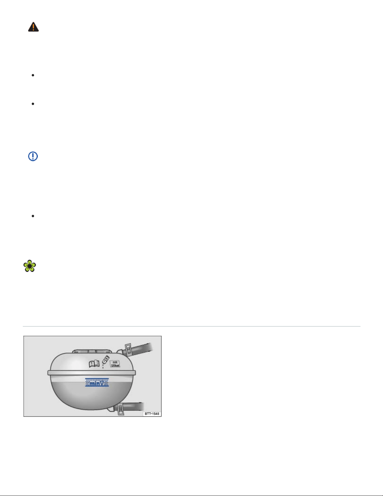
WARNING
Too little antifreeze protection in the engine cooling system can cause engine failure and severe
injuries.
Always make sure there is enough of the correct coolant additive to provide proper antifreeze
protection at the coldest temperatures that can be expected where the vehicle will be used.
At extremely cold temperatures, the coolant could freeze, causing the vehicle to break down.
The heater would also not work, and vehicle occupants could be without protection at sub‐
freezing temperatures.
NOTE
Never mix original Volkswagen engine coolant additives with other additives not approved by
Volkswagen. Mixing Volkswagen coolant additives with coolant additives made by other manufac‐
turers can seriously damage the engine and the engine cooling system.
If the fluid in the engine coolant reservoir is any color but pink, then - G13 - was mixed with
a different engine coolant. If this is the case, the engine coolant must be replaced immediately.
Otherwise serious malfunctions or engine damage can occur!
Engine coolant and engine coolant additives can pollute the environment. Collect leaking operat‐
ing fluids and dispose of them properly in accordance with applicable environmental laws and
regulations.
Checking engine coolant level and topping off
Fig.182Coolant expansion tank in the engine compartment.
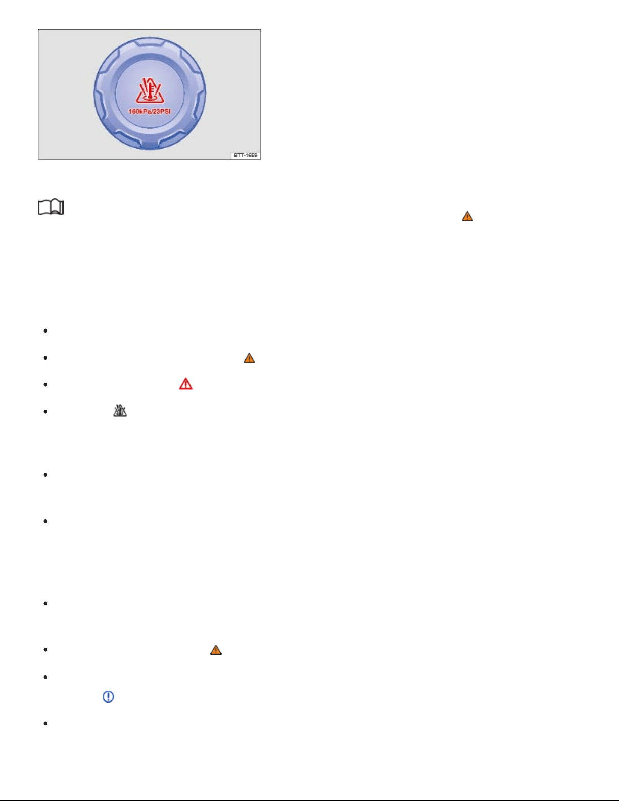
Fig.183Coolant expansion tank cap in the engine compartment.
Read and follow the introductory information and safety information first⇒ Introduction to the
subject
If the coolant level drops too low, the engine coolant level/temperature warning light comes on.
Preparations
Park the vehicle on level ground.
Always let the engine cool down ⇒ .
Open the engine hood ⇒Preparing to work in the engine compartment .
There is a symbol on the cap of the engine coolant expansion tank ⇒Fig.183 .
Checking engine coolant level
When the engine is cold, check the engine coolant level relative to the marking on the side of the
expansion tank ⇒Fig.182 .
If the coolant level in the tank is below the minimum mark (min), add coolant. When the engine is
warm, the engine coolant level may be slightly above the upper edge of the marked range.
Adding engine coolant
Always protect face, hands, and arms from hot escaping coolant or steam by covering the cap
with a large, thick rag.
Carefully unscrew the cap ⇒ .
Add only new engine coolant according to Volkswagen specifications (⇒Engine coolant specifica‐
tions ) ⇒ .
Only refill coolant if there is coolant in the expansion tank. If there is no coolant visible in the ex‐
pansion tank, the engine could be damaged. If you cannot see any coolant in the expansion tank,
do not drive the vehicle. Seek professional assistance.

If you can see coolant in the expansion tank, refill coolant until the level stays stable.
The engine coolant level must be inside the marks on the side of the expansion tank ⇒Fig.182 .
Do not fill above the top edge of the filling range!⇒
Screw the lid tightly.
Even in an emergency, do not use any other kind of coolant additive if engine coolant that meets
Volkswagen specifications (⇒Engine coolant specifications ) is not available! Instead, add dis‐
tilled water only⇒ . As soon as possible, have the correct coolant ratio restored using engine
coolant that meets Volkswagen specifications ⇒Engine coolant specifications .
WARNING
Hot steam and hot engine coolant can cause serious burns.
Never open the hood if you see steam or coolant escaping from the engine compartment.
Always wait until you no longer see or hear steam or coolant escaping from the engine.
Always let the engine cool down completely before carefully opening the hood. Hot compo‐
nents will burn skin on contact.
When the engine has cooled down and you are ready to open the hood:
Firmly apply the parking brake and shift the transmission into Park (P).
Take the vehicle key out of the ignition.
On vehicles with Keyless Access, make sure that the remote control vehicle key is out of
range of the vehicle and that the vehicle cannot be started by depressing the starter but‐
ton ⇒Starting and stopping the engine .
Always keep children and others away from the engine compartment and never leave
them unsupervised.
The engine coolant system is under pressure when the engine is hot. Never unscrew the
coolant expansion tank cap when the engine is hot. Hot coolant can spray out and cause se‐
vere burns and other serious injuries.
Turn the cap slowly and very carefully in a counterclockwise direction while applying light
downward pressure on the top of the cap.
Always protect your face, hands, and arms from hot escaping coolant or steam by cover‐
ing the cap with a large, thick rag.
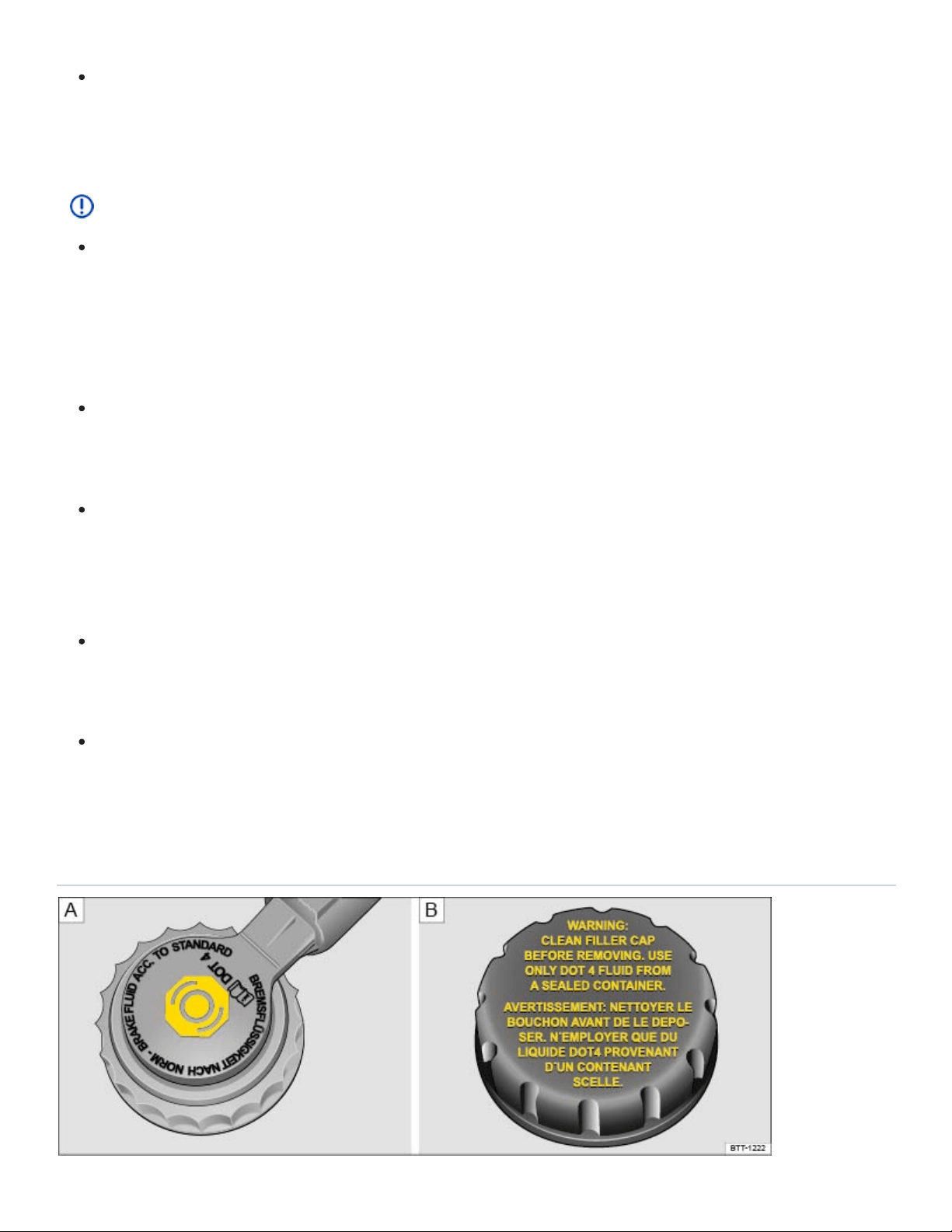
Never spill fluids on the engine or exhaust system when refilling. Spilling fluids onto hot parts
of the engine or exhaust system can cause a fire. Under some conditions, the ethylene glycol
in engine coolant can catch fire.
NOTE
Use distilled water only when adding coolant! All other types of water contain chemical com‐
pounds that can cause extensive corrosion damage to the engine. This can even lead to en‐
gine failure. If you have added non-distilled water, take the vehicle immediately to an autho‐
rized Volkswagen dealer or an authorized Volkswagen Service Facility to have the coolant sys‐
tem drained, flushed, and refilled completely with the proper coolant.
Refill engine coolant only up to the top edge of the marked fill range ⇒Fig.182 . Excess en‐
gine coolant may be forced out of the engine cooling system when it gets hot and cause
damage.
In the case of significant engine coolant loss, refill engine coolant only when the engine is
completely cooled down. Significant engine coolant loss is a sign of leaks in the cooling sys‐
tem. Have the engine cooling system checked immediately by an authorized Volkswagen
dealer or an authorized Volkswagen Service Facility. Otherwise the engine may be damaged!
Do not refill engine coolant if there is no coolant in the expansion tank. Air could enter the
cooling system. Do not drive the vehicle! Seek expert assistance. Failure to do so can result in
engine damage.
When changing or topping off operating fluids, make sure that you pour the fluids into the cor‐
rect reservoirs. Serious malfunctions and engine damage can result if you pour operating flu‐
ids into the wrong reservoir.
Brake fluid

Fig.184In the engine compartment: Brake fluid reservoir cap (cap design may vary depending on ve‐
hicle equipment).
Brake fluid absorbs water from the air over time. Too much water in the brake fluid will damage the
brake system. Water also lowers the boiling point of the brake fluid. Too much water in the brake fluid
can cause vapor lock during heavy brake use or hard braking. Vapor lock reduces braking perfor‐
mance, increases stopping distances and can even cause total brake failure. Your safety and the
safety of others depends on brakes that are working properly at all times ⇒ .
Brake fluid specifications
Volkswagen has developed a special brake fluid that is optimized for the brake system in your
Volkswagen. Volkswagen recommends that you use brake fluid that expressly conforms to quality
standard VW Standard 50114 for optimum performance of the brake system. Check the information
on the container for the brake fluid you want to use to make sure it meets the requirements for your
vehicle.
Brake fluid that complies with VW Standard 50114 can be purchased from your authorized
Volkswagen dealer or authorized Volkswagen Service Facility.
If this special brake fluid is not available you may – under these circumstances – use another high
quality brake fluid that complies with U.S. Federal Motor Vehicle Safety Standard (FMVSS)
116DOT4 Class 6 ⇒ .
Please note, however, that not all brake fluids that comply with U.S. Federal Motor Vehicle Safety
Standard (FMVSS) 116DOT4 Class 6 have the same chemical composition. Some of these brake
fluids can contain chemicals that could, over time, degrade or damage internal parts of the vehicle’s
brake system.
Volkswagen therefore recommends that you use brake fluid that expressly complies with VW
Standard 50114 for optimum brake system performance over the long term.
Brake fluid level
The fluid level in the transparent brake fluid reservoir must always be between the MIN and MAX
marking ⇒ .
On some vehicles, engine components may partially block the view of the brake fluid reservoir and
make it impossible to see the brake fluid level. If you cannot clearly see the brake fluid level in the
brake fluid reservoir, please see an authorized Volkswagen dealer or authorized Volkswagen Service
Facility.

The brake fluid level drops slightly when the vehicle is being used as the brake pads wear and the
brakes are automatically adjusted.
Brake fluid level
The red indicator light comes on.
The brake fluid level is too low.
Do not continue driving!
Check the brake fluid level.
If the brake fluid level is too low:
See your authorized Volkswagen dealer for assistance.
Have the brake system checked.
Changing brake fluid
Brake fluid must be changed according to the service schedule in your ⇒BookletWarranty and
Maintenance,. Have the brake fluid checked by an authorized Volkswagen dealer or an authorized
Volkswagen Service Facility. Refill only with new brake fluid that meets the standards listed above.
WARNING
Brake failure and reduced brake performance can be caused by not having enough brake fluid in
the reservoir or by old or incorrect brake fluid.
Have the brake system and brake fluid level checked regularly.
Have the brake fluid changed according to the service schedule in your ⇒BookletWarranty and
Maintenance,.
Hard braking with old brake fluid may cause vapor lock. Vapor lock reduces braking perfor‐
mance, increases stopping distances and can even cause total brake failure.
Only use brake fluid that expressly conforms to VW Standard 50114.
If a brake fluid that conforms to VW Standard 501 14 is not available, only use a high-quality
brake fluid that conforms to U.S. Standard FMVSS116DOT4 Class 6 requirements.
Brake fluid in an opened container can quickly become unusable. Refill your brake fluid reser‐
voir only with new brake fluid from an unopened container.

WARNING
Brake fluid is poisonous.
To reduce the risk of poisoning, never use food, beverage or other non-original containers to
store brake fluid. Someone might be misled by the original label on the container, or by the
shape of the container, and drink the brake fluid. This could occur even if you relabel the con‐
tainer as brake fluid.
Only store brake fluid in the closed, original container and keep it out of the reach of children.
NOTE
Brake fluid will damage vehicle paint, plastic parts, and tires. Wipe any brake fluid off vehicle
paint and other vehicle parts immediately.
Brake fluid can pollute the environment. Brake fluid that has leaked out must be collected and
disposed of properly, following all applicable environmental regulations.
Vehicle battery
Introduction to the subject
In this chapter you will find information on the following subjects:
⇒Checking the vehicle battery electrolyte level
⇒Charging, replacing, disconnecting, and connecting the vehicle battery
⇒Warning light
The standard 12Volt vehicle battery is part of the vehicle electrical system.
Never do any work on the vehicle electrical system unless you
know exactly how to carry out the job,
have the correct technical information and the proper tools, and
are familiar with the necessary safety precautions ⇒ !

If you are uncertain in any way, have the work done by an authorized Volkswagen dealer or autho‐
rized Volkswagen Service Facility. Serious personal injury may result from improperly performed
work.
Location of the vehicle battery
The 12Volt vehicle battery is in the engine compartment.
Explanation of the warnings on the vehicle battery
Always wear eye protection!
Battery acid is highly corrosive. Always wear protective gloves and eye protection!
Fire, sparks, open flame, and smoking are prohibited!
When a battery is charged, it produces hydrogen gas which is highly explosive!
Always keep children away from battery acid and vehicle batteries!
Always read and follow the information and WARNINGS in this Owner's Manual!
WARNING
Working on the batteries or the electrical system in your vehicle can cause serious acid burns,
fires, explosions, or electrical shocks. Always read and heed the following WARNINGS and
safety precautions before working on the batteries or the electrical system.
Before working on the electrical system, always switch off the ignition and all electrical con‐
sumers and disconnect the negative (-) cable from the standard 12Volt battery.
Always keep children away from battery acid and vehicle batteries in general.
When you change a light bulb, always switch off the light first.
Always wear eye protection. Never let battery acid or lead particles come into contact with
your eyes, skin, or clothing.
Sulfuric battery acid is very corrosive. It can burn unprotected skin and cause blindness.
Always wear protective gloves and eye protection. To reduce your risk of injury, never tilt the
batteries, as this could spill acid through the vents and burn you.
If you get battery acid in your eyes or on your skin, immediately rinse with cold water for sev‐
eral minutes and then get immediate medical attention. If you swallow any battery acid, get
medical attention immediately.
When disconnecting the batteries from the vehicle electrical system, always disconnect the
negative cable (-) first and then the positive cable (+).

Always switch off all electrical consumers before reconnecting 12Volt batteries. Reconnect the
plus cable (+) first and then the negative cable (-). Never reverse the polarity of the connec‐
tions. This could cause a fire.
A highly explosive mixture of gases is given off when the battery is being charged.
Do not smoke and avoid fires, sparks, and open flames when working. Never create sparks or
electrostatic charges when handling cables and electrical equipment. Never short circuit the
battery terminals. High-energy sparks can cause serious personal injury.
Never use or attempt to charge a damaged or frozen battery, or a battery that was frozen but
has thawed. Charging a frozen or thawed battery could cause explosions and chemical burns!
Replace damaged or frozen vehicle batteries immediately. A dead battery can freeze at tem‐
peratures around +32°F (0°C).
If the battery has a vent line or tube, make sure that it is properly connected to the battery.
WARNING
California Proposition65 Warning
Battery posts, terminals, and related accessories contain lead and lead components, chemi‐
cals known to the State of California to cause cancer and reproductive harm. Wash your hands
after handling.
NOTE
Do not expose the vehicle battery to direct sunlight for an extended period of time as ultraviolet
rays may damage the battery housing.
If the vehicle is left standing in the cold for a long time, protect the vehicle battery from freez‐
ing. A battery will be permanently damaged by freezing.
Emergency starting and starting the engine with a very weak vehicle battery or after the vehicle
battery has been replaced may change or delete system settings (including time, date, driver per‐
sonalization, and programming). Check the settings and correct as necessary once the vehicle
battery has built up a sufficient charge.
Checking the vehicle battery electrolyte level

Light yellow or colorless
Black
Fig.185In the engine compartment: Open the sleeve covering of the vehicle battery.
Read and follow the introductory information and safety information first⇒ Introduction to the
subject
Check the electrolyte level of the battery regularly if the vehicle has high mileage (km), in places with
a warm climate, and if the vehicle has an old battery. Otherwise the vehicle battery does not require
maintenance.
Preparations
Prepare the vehicle for work in the engine compartment ⇒Preparing to work in the engine com‐
partment .
Open the engine hood ⇒ .
Opening and closing the battery cover
To open, fold the cover to the side in the direction of the arrow ⇒Fig.185 .
To close, fold the cover against the direction of the arrow.
Checking the vehicle battery acid level
If the lighting conditions are poor, use a flashlight so that you can clearly see the battery acid level
indicator and tell what color it is. Never use an open flame or an unprotected light source.
The round battery window (acid level indicator) on the top of the battery changes color, depending
on the battery's electrolyte level.
Battery electrolyte level is too low. The vehicle battery may need to be re‐
placed. Have it checked by an authorized Volkswagen dealer or an authorized Volkswagen
Service Facility.
Battery electrolyte level is satisfactory.

WARNING
Working on the batteries can cause serious acid burns, explosion, or electrical shock.
Always wear eye protection and protective gloves.
Sulfuric battery acid is very corrosive. It can burn unprotected skin and cause blindness.
Always wear protective gloves and eye protection.
Never tilt the vehicle battery. Acid could spill out of the battery vents and burn you.
Never open a vehicle battery.
If you get battery acid in your eyes or on your skin, immediately rinse with cold water for sev‐
eral minutes and then get immediate medical attention.
If you swallow any battery acid, get medical attention immediately.
Charging, replacing, disconnecting, and connecting the vehicle battery
Read and follow the introductory information and safety information first⇒ Introduction to the
subject
Charging the vehicle battery
Vehicle batteries should be charged by an authorized Volkswagen dealer or an authorized
Volkswagen Service Facility because the factory-installed battery requires a charger with overload
protection ⇒ .
Replacing the vehicle battery
The battery in your vehicle is specially developed for its location, with special dimensions and safety
features. Before buying a new battery, ask an authorized Volkswagen dealer or authorized
Volkswagen Service Facility what batteries are suitable with regard to electro-magnetic compatibility,
dimensions, required maintenance, performance, and safety specifications.
Only use maintenance-free vehicle batteries meeting standards TL82506 and VW75073. These
standards must date from October 2014 or later.
In vehicles with a special vehicle battery, for example vehicles with a start-stop system, always re‐
place the vehicle battery with a battery with the same specifications.
Have the battery replaced by an authorized Volkswagen dealer or an authorized Volkswagen Service
Facility.

Disconnecting the vehicle battery
If the battery must be disconnected from the vehicle's electrical system, note the following:
Switch off all electrical systems and devices and the ignition.
Unlock the vehicle before disconnecting the battery; otherwise the alarm system will go off.
First disconnect the negative cable (-) and then the positive cable (+) ⇒ .
Connecting the vehicle battery
Prior to reconnecting the battery, switch off all electrical systems and devices and the ignition.
Connect the positive cable (+) first and then the negative cable (-) ⇒ .
After the battery is connected and the ignition is switched on, different indicator lights may light up.
They should go out after you drive a short distance at 10–12mph (15–20km/h). If the indicator lights
do not go out, contact an authorized Volkswagen dealer or an authorized Volkswagen Service Facility
and have the vehicle checked.
If the battery was disconnected for a long time, the next scheduled service may not be correctly cal‐
culated and displayed ⇒Instrument cluster . The maximum permissible service and maintenance in‐
tervals are shown in the ⇒BookletWarranty and Maintenance,.
Vehicles with Keyless Access: If the ignition will not start after reconnecting the vehicle battery, lock
the vehicle from the outside and unlock it again ⇒Doors and power locking system . Then try to start
the ignition again. If the ignition cannot be switched on, contact an authorized Volkswagen dealer, an
authorized Volkswagen Service Facility, or another qualified workshop for assistance.
Automatic electrical load deactivation
If the vehicle battery drain is high, the intelligent onboard electrical system management automatically
takes steps to help prevent battery drain.
The idle speed is increased so that the alternator provides more power.
The power to devices that consume a lot of electricity is cut back or switched off completely.
When the engine is started, the power supply to the 12Volt sockets is temporarily interrupted.
The onboard electrical system management cannot always keep the battery from being drained. For
example, the battery will drain if the engine is not running, but the ignition is switched on or the park‐
ing lights are left on for a long time when parked.

What drains the vehicle battery?
Long periods when the engine is not running, especially when the ignition is on.
Using electrical systems or devices when the engine is switched off.
Leaving the vehicle unlocked for several days when not in use.
The selector lever is left for a long period of time in any position other than Park (P) when the igni‐
tion is switched off.
WARNING
Failure to use the proper battery with proper mounting and connections may cause short circuits,
fires, and serious personal injuries.
Always use only maintenance-free or cycle-free, leak-proof batteries with the same specifica‐
tions and dimensions as the original equipment battery. Specifications are listed on the battery
housing.
WARNING
When the vehicle battery is charged, it produces highly explosive hydrogen gas.
Charge vehicle batteries only in well-ventilated areas.
Never charge a frozen or thawed battery. A dead battery can freeze at temperatures around
+32°F (0°C).
You must replace the vehicle battery if it was frozen.
Incorrectly connected cables can cause a short-circuit. First connect the positive cable (+) and
then the negative cable (-).
NOTE
Never disconnect the vehicle battery or connect 2vehicle batteries to each other when the ig‐
nition is switched on or the engine is running. Doing this may damage the electrical system or
electronic components.
Never use a vehicle battery that does not meet the specifications for the vehicle battery for
your vehicle. Using the wrong battery can damage the electrical system or electronic compo‐
nents and cause electrical malfunctions.

Never connect power generating equipment, such as a solar panel or battery charger, to the
12Volt socket in order to charge the vehicle battery. This can damage the vehicle's electrical
system.
Dispose of the vehicle battery according to regulations. Vehicle batteries contain poisonous sub‐
stances such as sulfuric acid and lead.
Battery acid can pollute the environment. Catch leaking operating fluids and dispose of them
properly.
Warning light
Read and follow the introductory information and safety information first⇒ Introduction to the
subject
When the ignition is switched on, several warning and indicator lights come on briefly for a function
check. They go out after a few seconds.
Alternator malfunction
The red warning light comes on.
Switch off unnecessary electrical loads. The vehicle battery will not be charged by the alternator
as you drive.
See an authorized Volkswagen dealer or an authorized Volkswagen Service Facility. Have the
electrical system checked.
WARNING
Failure to heed warning lights and instrument cluster text messages can result in a collision and
serious personal injury.
Never ignore warning lights or text WARNINGS.
Always stop the vehicle as soon as it is safe to do so.
Tires and wheels
Tire Pressure Monitoring System (TPMS)

Introduction to the subject
In this chapter you will find information on the following subjects:
⇒Indicator light (telltale)
⇒Recalibrating the Tire Pressure Monitoring System (TPMS)
Your vehicle's Tire Pressure Monitoring System (TPMS) uses the Anti-lock Brake System (ABS) sen‐
sors to indirectly check the tire pressure of all 4tires while you are driving. The sensors monitor the
tread circumference (rolling circumference) and vibration characteristics of the individual tires. TPMS
warns if there is a significant loss of pressure in one or more tires while the vehicle is moving.
Pressure loss is signaled by the indicator light (described below) as well as by acoustic warnings
and text warnings in the instrument cluster display if your vehicle has this display Infotainment system
or the Multi-Function Display (MFD).
The original benchmark pressure is the recommended maximum load cold tire inflation pressure for
the tires that come with your vehicle. This pressure is listed on the tire pressure label on the driver
door jamb ⇒Tire inflation pressure . After adjusting the tire pressures in all 4tires, you must confirm
and store the new cold inflation pressures through the Infotainment system, which changes the
benchmark pressure to match the current pressure of the tires on your vehicle ⇒Recalibrating the
Tire Pressure Monitoring System (TPMS) .
Recalibrating the TPMS to reset the benchmark cold tire inflation pressure is explained on
⇒Recalibrating the Tire Pressure Monitoring System (TPMS) .
WARNING
Incorrect tire pressures and/or underinflation can cause sudden tire failure, loss of control, colli‐
sion, serious personal injury or even death.
When the warning symbol appears in the instrument cluster, stop and inspect the tires.
Incorrect tire pressure and/or underinflation can cause increased tire wear and can affect the
handling of the vehicle and stopping ability.
Incorrect tire pressures and/or underinflation can also lead to sudden tire failure, including a
blowout and sudden deflation, causing loss of vehicle control.
The driver is responsible for the correct tire pressures for all tires on the vehicle. The recom‐
mended tire pressure values are listed on a sticker inside the driver door ⇒Tire inflation pres‐
sure .

The TPMS can only work correctly when all tires on the vehicle are filled to the correct cold tire
inflation pressure.
Using incorrect tire pressure values can cause accidents or other damage. Always inflate the
tires to the correct specified cold tire pressure values for the tires installed on the vehicle.
Always maintain correct cold tire inflation pressure so that TPMS can do its job.
Always inflate tires to the recommended and correct tire pressure before driving off.
Driving with underinflated tires causes them to flex (bend) more, letting them get too hot, re‐
sulting in tread separation, sudden tire failure, and loss of control.
Excessive speed and/overloading can cause heat buildup, sudden tire failure and loss of
control.
If the tire pressure is too low or too high, the tires will wear prematurely and the vehicle will not
handle well.
If the tire is not flat and you do not have to change a wheel immediately, drive carefully and at
reduced speed to the nearest service station to check the tire pressure and add air as
required.
When replacing tires or wheel rims on vehicles equipped with TPMS always read and heed the
information and all WARNINGS regarding ⇒Tires and wheels .
The Tire Pressure Monitoring System must be recalibrated whenever you remove and remount
or change any wheel or tire on the vehicle, even if the reinstalled or replacement wheels and
tires are identical to those that were removed and even if the tire pressure does not change
⇒Tire inflation pressure .
WARNING
Improper recalibration can cause the TPMS to give false warnings or to give no warning despite
dangerously low tire pressure ⇒Recalibrating the Tire Pressure Monitoring System (TPMS) .
Underinflation increases fuel consumption and tire wear.
Do not rely solely on the Tire Pressure Monitoring System. Check your tires regularly to make
sure they are properly inflated and have no signs of damage, such as punctures, cuts, cracks,
and blisters. Remove any objects that become embedded in the tire tread but have not pene‐
trated into the body of tire itself.

When you take delivery of the vehicle, the Tire Pressure Monitoring System is calibrated for the
factory-recommended cold tire inflation pressure for the tires on your vehicle, as shown on the la‐
bel inside the driver door ⇒Tire inflation pressure .
The system must be recalibrated through the Infotainment system whenever you remove and re‐
mount or change any wheel or tire on the vehicle, even if the reinstalled or replacement wheels
and tires are identical to those that were removed and even if the tire pressure does not change
⇒Recalibrating the Tire Pressure Monitoring System (TPMS) .
If you have to adjust the tire pressure on a warm tire, fill the tire with 2.0- 4.35psi (20- 30kPa)
more than the pressure specified on the tire pressure label inside the driver door ⇒Tire inflation
pressure .
At the next opportunity, check and adjust the tire pressure on all 4 tires when they are cold. Cold
tires are tires that have not been driven more than a couple of miles (kilometers) at low speed
within the last 3 hours. Then be sure to recalibrate the TPMS.
If the TPMS determines that the air pressure in at least one tire is too low, carefully check the
pressure in all 4tires with an accurate tire pressure gauge. Low tire pressure usually cannot be
determined by looking at the tire. This is especially true of low-profile tires.
If you have work done on your wheels or tires, inform the workshop that the vehicle is equipped
with a Tire Pressure Monitoring System (TPMS).
New tires may expand slightly the first time they are driven at high speeds, which can trigger a
tire pressure warning. Remember that tire pressure can only be properly measured when the tire
is cold ⇒Tire inflation pressure .
Only replace old tires with tires that have been approved by Volkswagen for your vehicle type.
Indicator light (telltale)
Read and follow the introductory information and safety information first⇒ Introduction to the
subject
Lights up
Possible cause or meaning ⇒
Proper response

Lights up
Possible cause or meaning ⇒
Proper response
Lights up and a chime may also sound.
The inflation pressure of one or more tires
is significantly lower than the benchmark
pressure set by the driver or a tire has
structural damage. Depending on vehicle
equipment, a message may also appear
in the instrument cluster display.
Stop safely as soon as possible!
Reduce speed immediately! Avoid fast corner‐
ing and hard braking!
Check the condition and inflation pressure of
all tires. Have damaged tires replaced.
Flashes
Possible cause or meaning ⇒
Proper response

Flashes
Possible cause or meaning ⇒
Proper response
Flashes for about a minute and then stays
on:
System malfunction.
Check and, if necessary, adjust the tire infla‐
tion pressure in all fourtires. If the tire pres‐
sure is correct, switch the ignition off and back
on. If the indicator light flashes again and then
stays on or does not go out after checking
and adjusting the air pressure in all fourtires
and recalibrating, take the vehicle to an au‐
thorized Volkswagen dealer or an authorized
Volkswagen Service Facility. Have the system
checked.
When the ignition is switched on, several warning and indicator lights come on briefly for a function
check. They go out after a few seconds.
WARNING
Incorrect tire pressures and/or underinflation can cause sudden tire failure, loss of control, colli‐
sion, serious personal injury, or even death.
When the warning symbol appears in the instrument cluster, stop the vehicle as soon as it
is safe to do so and inspect all tires.
Incorrect tire pressure and/or underinflation can cause increased tire wear and can affect the
handling of the vehicle and its stopping ability.
Incorrect tire pressure and/or underinflation can also lead to sudden tire failure, including a
blowout and sudden deflation, causing loss of vehicle control.
The driver is responsible for the correct tire pressures for all tires on the vehicle. The recom‐
mended tire pressure values are listed on a sticker inside the driver door ⇒Tire inflation pres‐

sure .
The TPMS can only work correctly when all tires on the vehicle are filled to the correct cold tire
inflation pressure. Always maintain the correct cold tire inflation pressure so that TPMS can do
its job.
Using incorrect tire pressure values can cause accidents or other damage. Check the pressure
in all 4tires when the tires are still cold. Never reduce air pressure in warm tires to match cold
tire inflation pressure.
Always inflate the tires to the correct specified cold tire pressure values for the tires installed
on the vehicle; see the tire inflation pressure label on the driver door jamb ⇒Tires and
wheels .
Always inflate tires to the recommended and correct tire pressure before driving off.
Driving with underinflated tires causes them to flex (bend) more, letting them get too hot, which
can result in tread separation, sudden tire failure, and loss of control.
Excessive speed and/or overloading can cause heat buildup, sudden tire failure, and loss of
control.
If the tire pressure is too low or too high, the tires will wear prematurely and the vehicle will not
handle well.
If the tire is not flat and you do not have to change the tire or wheel immediately, drive at re‐
duced speed to the nearest service station to check the tire pressure and add air as required.
When replacing tires or wheel rims on vehicles equipped with TPMS, always read and heed
the information and all WARNINGS in the section ⇒Tires and wheels .
The Tire Pressure Monitoring System must be recalibrated whenever you remove and remount
or change any wheel or tire on the vehicle, even if the reinstalled or replacement wheels and
tires are identical to those that were removed and even if the tire pressure does not change
⇒Recalibrating the Tire Pressure Monitoring System (TPMS) .
WARNING
Improper recalibration can cause the TPMS to give false warnings or to give no warning despite
dangerously low tire pressure ⇒Recalibrating the Tire Pressure Monitoring System (TPMS) .
WARNING

Failure to heed warning lights and instrument cluster text messages can result in a collision and
serious personal injury.
Never ignore warning lights or text WARNINGS.
Always stop the vehicle as soon as it is safe to do so.
NOTE
Failure to heed warning lights or text WARNINGS can result in vehicle damage.
If the ignition is switched on, an acoustic warning sounds when low tire pressure is detected. An
acoustic warning also sounds if a system malfunction is detected.
Driving for a longer period of time on rough roads or with a dynamic and sporty style can make
the TPMS system temporarily unavailable. The indicator light will come on, signaling a malfunc‐
tion, but will go out again once the road condition or driving style changes.
Recalibrating the Tire Pressure Monitoring System (TPMS)
Read and follow the introductory information and safety information first⇒ Introduction to the
subject
Your vehicle's Tire Pressure Monitoring System (TPMS) indirectly checks the tire pressure of all
4tires while you are driving by using the Anti-lock Brake System (ABS) sensors to monitor the tread
circumference (rolling circumference) and vibration characteristics of the individual tires.
The tread circumference of a tire can change:
If a tire's inflation pressure is too low.
If the tire's tread is damaged or the tire is structurally damaged.
If one side of the vehicle is more heavily loaded than the other.
If there is more weight on one axle than the other (such as when towing a trailer).
If a compact spare wheel has been mounted.
If a wheel was replaced on each axle.

If a tire was changed.
If the tire pressure was changed, or wheels were rotated or replaced.
If there are snow chains on the tires. Using snow chains can cause the system to give false warn‐
ings because snow chains increase tire circumference.
The Tire Pressure Monitoring System (TPMS) may not react at first or may not react at all when
you are driving in a sporty manner, or on snow-covered or unpaved roads, when you are driving with
snow chains, or in certain other situations. A change in the tread circumference of a tire is signaled by
the Tire Pressure Monitoring System indicator in the instrument cluster (telltale).
The tire pressure recommended for the tires originally installed on the vehicle is on a sticker on the
driver door jamb ⇒Tires and wheels .
Each tire, including the spare (if provided), should be checked monthly when cold and inflated to the
inflation pressure recommended by the vehicle manufacturer on the vehicle placard or tire inflation
pressure label. (If your vehicle has tires of a different size than the size indicated on the vehicle plac‐
ard or tire inflation pressure label, you should determine the proper tire inflation pressure for those
tires.)
As an added safety feature, your vehicle has been equipped with a Tire Pressure Monitoring System
(TPMS) that illuminates a low tire pressure telltale when one or more of your tires is significantly un‐
derinflated. Accordingly, when the low tire pressure telltale illuminates, you should stop and check
your tires as soon as possible, and inflate them to the proper pressure. Driving on a significantly un‐
derinflated tire causes the tire to overheat and can lead to tire failure. Underinflation also reduces fuel
efficiency and tire tread life, and may affect the vehicle's handling and stopping ability.
Please note that the TPMS is not a substitute for proper tire maintenance, and it is the driver's re‐
sponsibility to maintain correct tire pressure, even if underinflation has not reached the level to trigger
illumination of the TPMS low tire pressure telltale.
Your vehicle has also been equipped with a TPMS malfunction indicator to indicate when the system
is not operating properly. The TPMS malfunction indicator is combined with the low tire pressure tell‐
tale. When the system detects a malfunction, the telltale will flash for approximately one minute and
then remain continuously illuminated. This sequence will continue upon subsequent vehicle start-ups
as long as the malfunction exists.
When the malfunction indicator is illuminated, the system may not be able to detect or signal low tire
pressure as intended. TPMS malfunctions may occur for a variety of reasons, including the installa‐
tion of replacement or alternate tires or wheels on the vehicle that prevent the TPMS from functioning

properly. Always check the TPMS malfunction telltale after replacing one or more tires or wheels on
your vehicle to ensure that the replacement or alternate tires and wheels allow the TPMS to continue
to function properly.
Resetting and recalibrating the benchmark tire pressure
Resetting the tire pressures in the Infotainment system resets the benchmark tire pressure used by
the TPMS to the current tire pressure in the tires based on the circumference of the tires.
Switch on the ignition.
Press the Infotainment button ⇒Infotainment system operation and displays .
Tap the Vehicle and function keys to open the Vehicle settings menu.
Tap the Tires function key.
Tap the SET function key in the Tire Pressure Monitoring System menu.
If all 4 wheels are set to the correct values, touch the Confirm function key to store the tire
pressures.
Touching the Cancel button will prevent the current tire pressures from being stored and the sys‐
tem will not be recalibrated.
The recalibration must be performed each time the tire pressure in one or more tires has been ad‐
justed or after one or more tires has been changed, exchanged, or repaired. The new tire pressures
are stored in the system only after at least 20minutes of normal driving.
If you have reset the benchmark tire pressure when your tires do not have the correct tire pressure,
this will prevent the TPMS from working properly. It may then give false warnings or may not give any
warning even if the tire pressure is too low.
For this reason, it is vital to make certain that all 4tires are inflated to the correct pressure
when they are cold before calibrating the system. Cold tires are tires that have not been driven
more than a couple of miles (kilometers) at low speed within the last 3hours.
During normal vehicle operation, the system calibrates itself to the tires installed and the changed tire
pressures. The calibrated values are stored and monitored after a long journey at various speeds.
If the wheels are loaded more heavily than normal, for example, if the vehicle is carrying heavy load,
the tire pressure must be raised to the recommended full-load tire pressure before recalibaration
⇒Tires and wheels .

Recalibrate the system to reset the benchmark TPMS pressure in the following situations:
After installing tires on your vehicle that have recommended cold tire inflation pressures that are
different from the tires that were taken off.
After any tire on your vehicle is removed and then remounted, even if the same tire and wheel rim
that were taken off are reinstalled (for instance, after repair).
After any tire on your vehicle is changed and replaced by another tire, even if the replacement tire
is the same type and is inflated to the same pressure as the tire it replaced.
After adjusting the tire pressure of any tire on the vehicle to its correct cold tire inflation pressure,
either by putting air in one or more tires or by letting air out. Do this even though air was only
added (or let out) to bring the tire to the inflation pressure it should have had all along.
After rotating the front and rear wheels ⇒Tires and wheels .
After mounting the compact spare wheel.
WARNING
Incorrect recalibration can cause the TPMS to give false warnings or to give no warning despite
dangerously low tire pressure. Make certain the tire inflation pressure of all tires is correct before
recalibrating the system.
WARNING
Incorrect tire pressure can cause sudden tire failure, loss of vehicle control and serious personal
injury.
Always check and correct air pressure in all 4tires, particularly after changing, exchanging, or
repairing tires.
After that, always make sure that all 4tires are inflated to the correct tire pressure for the tires
installed on the vehicle. Then recalibrate the system so that it can properly monitor the pres‐
sure in the tire.
See the tire pressure label ⇒Tire inflation pressure and the Owner's Literature for recom‐
mended cold tire inflation pressure and other important information.
When replacing tires or wheel rims, always read and heed all of the information and
WARNINGS ⇒Tires and wheels .
The Tire Pressure Monitoring System must be recalibrated whenever you remove and remount
or change any wheel or tire on the vehicle, even if the reinstalled or replacement wheels and

tires are identical to those that were removed and even if the tire pressure does not change.
The Tire Pressure Monitoring System stops working if there is an ESC/ABS malfunction
⇒Braking assistance systems .
After a low tire pressure warning, the vehicle must stand and must not be driven for at least
1minute before the new benchmark tire pressures can be stored.
Important information on tires and wheels
Introduction to the subject
In this chapter you will find information on the following subjects:
⇒Tire and wheel handling
⇒Wheel rims and bolts
⇒New and replacement tires
⇒Tire inflation pressure
⇒Tire inflation pressure in cold tires
⇒Tread depth and tread wear indicators
⇒Tire wear and damage
⇒Compact spare wheel
⇒Tire labeling
⇒Winter tires
⇒Snow chains
⇒Glossary of tire and loading terminology

⇒Tires and vehicle load limits
⇒Determining the correct load limit
⇒UTQG classification
Volkswagen recommends that all work on tires and wheels be done by an authorized Volkswagen
dealer or authorized Volkswagen Service Facility. They are familiar with the technical requirements
and recommended procedures, have the necessary special tools and spare parts, and can properly
dispose of old tires.
WARNING
New tires or tires that are old, worn or damaged cannot provide maximum control and braking
performance.
Improper care and handling of tires and wheels can reduce driving safety and cause accidents
and severe injuries.
Install only radial tires of the same make, the same dimensions (tread circumference), and
similar tread profile on all 4wheels.
New tires tend to be slippery and must be broken in. Always drive with special care for the first
350miles (560km) to help reduce the risk of losing control, a collision, and serious personal
injuries.
Check tire inflation pressure regularly when the tires are cold and always maintain the pre‐
scribed tire pressure. Low tire pressure can cause tires to get too hot, resulting in tread sepa‐
ration, sudden loss of pressure, and blowouts. Tires with excessively low pressure flex (bend)
more, which can cause the tire to overheat and fail suddenly without warning.
Check tires regularly for wear and damage.
Never drive with worn or damaged tires (for example, tires with punctures, cuts, cracks, blis‐
ters, or bumps). Driving with worn or damaged tires can lead to loss of vehicle control, sudden
tire failure including blowouts and sudden deflation, crashes, and serious personal injuries.
Have worn or damaged tires replaced immediately.
Never exceed the maximum speed rating or the maximum load rating of the tires on your
vehicle.

The effectiveness of the driver assistance systems and the braking support systems depends
on the tire traction.
If you notice unusual vibration or if the vehicle pulls to one side when driving, always stop as
soon as it is safe to do so and check the wheels and tires for damage.
To reduce the risk of losing control, crashes, and serious personal injuries, never loosen the
bolts on wheels with bolted rim rings.
Never mount used tires on your vehicle if you are not sure of their past use. Old, used tires
and wheels may have damage that cannot be seen that can lead to sudden tire failure and
loss of vehicle control.
Tires age even if they are not being used and can fail suddenly, especially at high speeds,
causing loss of vehicle control, accidents, and severe personal injuries. Tires that are more
than 6years old can be used only in an emergency and even then only with special care and
at low speed.
WARNING
Improperly tightened or missing wheel bolts can come loose while driving, causing loss of vehicle
control, collisions, and serious personal injuries.
Never drive with missing or loose wheel bolts.
Only use wheel bolts that are designed for your vehicle and for the wheel being installed.
Always tighten the wheel bolts to the correct tightening torque. If you do not have a torque
wrench, tighten the wheel bolts with a lug wrench and have the torque checked as soon as
possible by an authorized Volkswagen dealer or authorized Volkswagen Service Facility.
For technical reasons it is usually not possible to use wheel rims from other vehicles. Even wheel
rims from the same model may not fit properly. Check with an authorized Volkswagen dealer or
authorized Volkswagen Service Facility if necessary.
Tire and wheel handling
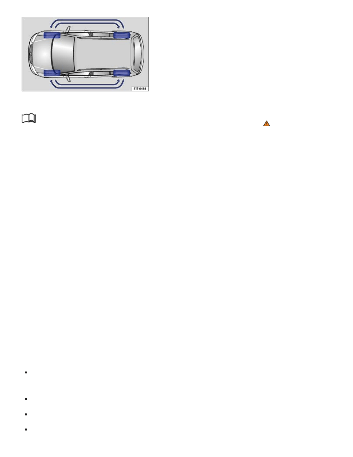
Fig.186Tire rotation diagram.
Read and follow the introductory information and safety information first⇒ Introduction to the
subject
Tires may be the least appreciated and most abused parts of a motor vehicle. Tires are very impor‐
tant, since their small patches of rubber are the only contact between your vehicle and the road.
Maintaining correct tire pressure, making sure that your vehicle and its tires do not have to carry more
weight than they can safely handle, and regularly inspecting tires for damage (such as cuts, slashes,
irregular wear, and overall condition) are the most important things that you can do to help avoid sud‐
den tire failure, including tread separation and blowout.
The tires and wheels are essential parts of the vehicle's design. The tires and wheels approved by
Volkswagen are specially matched to the characteristics of the vehicle for good road holding and safe
handling when in good condition and properly inflated.
Rotating tires
To help ensure even wear on all tires, regular tire rotation according to the diagram ⇒Fig.186 is rec‐
ommended. In this way all tires can have about the same service life.
Volkswagen recommends that you have your tires rotated by an authorized Volkswagen dealer or au‐
thorized Volkswagen Service Facility.
Avoiding tire damage
If you must drive over a curb or other obstacle, drive very slowly and as much as possible at a
right angle to the curb with the tire tread of both front wheels contacting the curb at the same time.
Regularly check tires for damage, such as punctures, cuts, tears and blisters.
Never exceed the load and permissible maximum speed rating of the tires ⇒Tire labeling .
Replace worn or damaged tires immediately ⇒Tire wear and damage .

Always keep aggressive chemicals including grease, oil, gasoline and brake fluid off the tires, in‐
cluding the compact spare wheel ⇒ .
Replace missing valve caps immediately.
Remove embedded material in the tread profile that has not yet penetrated the inside of the
tire⇒Tire wear and damage .
Heed all warning messages from the Tire Pressure Monitoring System (TPMS) ⇒Tire Pressure
Monitoring System (TPMS) .
Damage to tires and wheels is often not readily visible. If you notice unusual vibration or the vehi‐
cle pulls to one side, this may indicate that one of the tires is damaged. The tires must be checked
immediately for hidden damage by an authorized Volkswagen dealer or an authorized
Volkswagen Service Facility. See also ⇒Tire wear and damage .
Unidirectional tires
Unidirectional tires are designed to rotate only in one direction. Unidirectional tires have arrows on the
sidewalls that show the direction of rotation ⇒Tire labeling . Unidirectional tires must always be
mounted according to the specified direction of rotation in order to deliver their best grip, braking per‐
formance, low road noise, and good wear as well as good hydroplaning resistance.
If you have to mount a tire opposite to its proper direction of rotation, you must drive more carefully,
since the tire is no longer being used as designed. This is particularly important on wet roads. You
must replace or remount the tire as soon as possible in order to restore the correct direction of
rotation.
Tires more than 6 years old
Tires age even if they are not being used. Physical and chemical processes reduce tire strength and
performance and cause them to harden and become brittle. Old tires can fail suddenly and without
warning.
Volkswagen recommends replacing tires that are 6 years and older. This also applies to tires that look
new (including the tire on the compact spare wheel) or that seem to still be usable with tread depth
that has not yet reached the legal minimum depth ⇒ .
The age of each tire can be determined with the manufacturing date that is part of the U.S. DOT tire
identification number (TIN)⇒Tire labeling .
Tire storage

Mark tires before removing them to help make sure that the previous location (left, right, front, rear)
and rolling direction can be maintained when remounting them. Store tires in a cool, dry and prefer‐
ably dark place. Do not store tires mounted on wheels standing up.
Tires not mounted on wheels should be covered to help protect them from dirt and stored vertically
(sitting on the tread).
Lower profile tires (low aspect ratio tires)
Lower profile tires have a wider tread surface, larger rim diameter, and lower sidewalls than conven‐
tional wheel/tire combinations ⇒ . Lower profile tires can improve the vehicle’s handling and preci‐
sion. They may, however, result in a less comfortable ride, for example, on uneven road surfaces.
WARNING
Aggressive fluids and materials can cause visible and invisible tire damage that can cause tire
blowouts.
Always keep chemicals, oils, grease, fuels, braking fluids and other aggressive substances
away from tires.
WARNING
Tires age even if they are not being used and can fail suddenly, especially at high speeds, caus‐
ing loss of vehicle control, accidents, and severe personal injuries.
Tires that are more than 6 years old can be used only in an emergency and even then only
with special care and at low speed.
NOTE
Tires and rims, especially lower profile tires and their rims, can be severely damaged and even
destroyed by driving through potholes or over curbs and other obstacles.
Always dispose of old tires in accordance with legal requirements.
Wheel rims and bolts

Read and follow the introductory information and safety information first⇒ Introduction to the
subject
The design of the wheel bolts is matched to the factory-installed wheels. If different wheels are in‐
stalled, wheel bolts with the right length and bolt head shape must be used. This helps to ensure that
wheels can be mounted securely and that the brakes will work correctly ⇒Changing a wheel .
In most cases, you cannot use wheel rims or bolts from a different vehicle. Even wheel rims from the
same model may not fit properly.
Tires and wheel rims approved by Volkswagen have been matched precisely to your vehicle model
and contribute considerably to good handling and safe vehicle performance.
The wheel bolt tightening torque must be checked regularly with an accurate torque wrench.
Two-piece wheel bolts
The correct wheel bolts must be used for all vehicle types. these bolts must always be tightened with
the correct tightening torque ⇒Tightening torque . The designated wheel bolts for your vehicle are
two-piece wheel bolts with a rotating shoulder.
Tightening torque
Wheel bolts must always be installed with the correct tightening torque ⇒Changing a wheel . The re‐
quired tightening torque for your vehicle's wheel bolts is 88 ft-lbs (120 Nm). After changing a wheel,
the bolt torque must be checked as soon as possible with an accurate torque wrench. See an autho‐
rized Volkswagen dealer or an authorized Volkswagen Service Facility.
Wheel rims with bolted rim rings
Wheel rims with bolted rim rings have several parts. The parts are bolted together with special screws
in a special process. This helps to ensure that they will work properly, prevent leaks, run true and
safely. Damaged wheel rims must be replaced, and you must never take them apart or try to repair
them yourself. Have an authorized Volkswagen dealer or an authorized Volkswagen Service Facility
repair them for you ⇒ .
Wheel rims with bolted decorative covers
Light-alloy wheels may have interchangeable decorative covers attached to the rim with self-locking
screws. If you want to replace damaged wheel covers, contact your authorized Volkswagen dealer or
an authorized Volkswagen Service Facility ⇒ .

WARNING
Using improper or damaged wheel rims can affect driving safety, cause accidents and severe
personal injury.
Use only wheel rims approved for the vehicle.
Regularly check wheel rims for damage and replace them if necessary.
WARNING
Improper loosening and tightening of the bolts on wheel rims with bolted rim rings can cause ac‐
cidents and severe personal injury.
Never loosen bolted connections on wheel rims with bolted rim rings.
Have all work on wheel rims with bolted rim rings performed by an authorized Volkswagen
dealer or authorized Volkswagen Service Facility.
New and replacement tires
Read and follow the introductory information and safety information first⇒ Introduction to the
subject
New tires
Drive a vehicle with new tires especially carefully for the first 350miles (560km) because the tires
must first be broken in. Tires that are not broken in have reduced traction and braking perfor‐
mance ⇒ .
Install only radial tires of the same make, the same dimensions (tread circumference), and similar
tread profile on all 4wheels.
The tread depth of new tires can differ between tire models and manufacturers because of differ‐
ent design features and tread design.
Replacing tires
Tires should be replaced in pairs and not individually (both front tires or both rear tires at the same
time) ⇒ .
Replace tires only with tires that have the same specifications, including width and diameter, load
and top speed rating as the tires approved by Volkswagen for your vehicle and model.

Never use tires that are larger or wider than the dimensions of the tires approved by Volkswagen
for your vehicle and model. Larger tires could scrape and rub on the vehicle body or other parts of
the vehicle.
Tire Pressure Monitoring System (TPMS) considerations: The Tire Pressure Monitoring System
(TPMS) must be recalibrated whenever you remove and remount or change any wheel or tire on the
vehicle, even if the reinstalled or replacement wheels and tires are identical to those that were re‐
moved and even if the tire pressure does not change ⇒Tire Pressure Monitoring System (TPMS) .
WARNING
New tires tend to be slippery and must be broken in.
Always drive with special care for the first 350miles (560km) to help reduce the risk of losing
control, a collision, and serious personal injuries.
WARNING
Tires must have the required clearance. Tires that do not have enough clearance can rub against
parts of the vehicle body, suspension, and brake system, causing brake system failure, tread de‐
lamination, and sudden blowouts.
Always make sure that new tires are not larger than the tires approved for your vehicle and
that the new tires do not rub against parts of the vehicle.
NOTE
When switching to different tires, make certain the valves are not damaged.
Never drive without valve stem caps. The valves could be damaged.
If the sensor on the Tire Pressure Monitoring System (TPMS) must be replaced, the valve
must be replaced at the same time.
Always dispose of old tires in accordance with legal requirements.
If the replacement wheel is different from the tires that you have mounted on your vehicle — for
example, winter tires, wider, low-profile tires, or a compact spare — only use the replacement
wheel for a short time and drive cautiously.
Replace it with a tire matching the others on your vehicle as soon as possible.

Although tire size specifications can be the same, the actual dimensions may differ from those
nominal values for different tire makes, or the tire contours may be significantly different.
Tire inflation pressure
Fig.187On the driver door jamb: Location of the tire inflation pressure label.
Read and follow the introductory information and safety information first⇒ Introduction to the
subject
The correct tire inflation pressure for the factory-installed tires is listed on a label. The factory-installed
tires may be summer, winter, or all-season tires. The label ⇒Fig.187 is on the driver door jamb.
Under- or over-inflation significantly shortens the service life of your tires and affects the handling of
the vehicle ⇒ . The correct tire pressure is very important, particularly when the vehicle is driven at
higher speeds. Incorrect tire pressure causes increased wear and even sudden tire failure and
blowouts.
The specified tire inflation pressure applies to a cold tire. When tires are warm, the pressure will be
higher than when the tires are cold.
Do not reduce the tire pressure on warm tires to match the required cold tire inflation pressure. The
tire inflation pressure would then be too low and could cause sudden tire failure and blowout.
Checking tire inflation pressure
Tire pressure should be checked at least once a month and always before long trips.
Always check the tire pressure only on cold tires when the vehicle has not been driven more than
a couple of miles (kilometers) at low speed within the last 3hours.

Check tire inflation pressure regularly and on cold tires. Check all the tires, including the compact
spare, if any. In colder climates tire pressure should be checked more often, but only when the
tires are cold. Always use an accurate tire pressure gauge.
After adjusting the tire inflation pressures, make sure to screw the valve caps back on; replace
missing valve caps immediately. Please read and heed the information about the Tire Pressure
Monitoring System (TPMS), if necessary ⇒Tire Pressure Monitoring System (TPMS) .
Remember that the vehicle manufacturer, not the tire manufacturer, determines the correct tire
pressure for the tires on your vehicle. Never exceed the maximum inflation pressure listed on the
tire sidewall for any reason.
Inflate a spare wheel to the pressure specified for the vehicle's road wheels on the tire pressure la‐
bel; inflate a compact spare wheel to the pressure specified for the compact spare on the tire pres‐
sure label or on a separate label for the compact spare, if there is one.
WARNING
Incorrect tire pressure can cause a sudden tire failure or blowout, loss of control, collision, seri‐
ous personal injury, and even death.
Always inflate tires to the recommended and correct cold tire pressure before driving off.
Low tire pressure can cause tires to get too hot, resulting in tread separation, sudden loss of
pressure, and blowouts. Tires with excessively low pressure flex (bend) more, which can
cause the tire to overheat and fail suddenly without warning.
Excessive speed and/or overloading can cause heat buildup, sudden tire failure including a
blowout and sudden deflation and loss of control.
If the tire pressure is too low or too high, the tires will wear prematurely and the vehicle will not
handle well.
Regularly check tire inflation pressure, at least once a month, and also especially before a
long trip.
Check the pressure in all 4tires when the tires are still cold. Never reduce air pressure in
warm tires to match cold tire inflation pressure.
NOTE
Make sure not to jam the tire pressure gauge into the valve stem. Otherwise, you can damage
the tire valves.

Driving without valve caps, with the wrong valve caps, or with valve caps that are not properly
screwed on can damage the tire valves. To help prevent damage, always use valve stem caps
like those originally installed at the factory. The caps must be screwed on tightly. Do not use
metal valve caps or comfort valve stem caps.
Underinflation increases fuel consumption.
When the TPMS warns that the pressure in at least one tire is too low, check the tire pressure in
all 4tires with an accurate tire pressure gauge. Low tire pressure usually cannot be spotted by
looking at the tire. This is especially true for low-profile tires. When checking the tire pressures,
refer to ⇒Tire Pressure Monitoring System (TPMS) .
Tire inflation pressure in cold tires
Read and follow the introductory information and safety information first⇒ Introduction to the
subject
Engine Tire dimensions
Tire pressure
PSI / kPa
2.0 l / 238 hp (175 kW)
245/60 R 18 30 / 210
255/50 R 20 30 / 210
265/45 R 21 32 / 220
3.6l / 280hp (206kW) 245/60 R 18 35 / 240
255/50 R 20 35 / 240
265/45 R 21 35 / 240
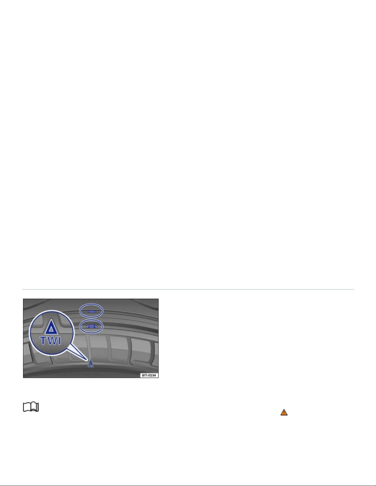
Engine Tire dimensions
Tire pressure
PSI / kPa
245/65 R17 35 / 240
Compact spare wheel T165/80 R 17 60 / 420
The Tire Pressure Monitoring System (TPMS) is configured at the factory with the correct tire inflation
pressure applicable for the vehicle model, engine and factory-installed tires. The tire inflation pressure
is listed on the tire inflation pressure label on the driver door jamb ⇒Fig.187 . The tire inflation pres‐
sures for the road tires are listed on this label. The inflation pressure for the compact spare is as
specified on the tire pressure label or on a separate label for the compact spare, if there is one. In the
event of a discrepancy between the above figures and the tire pressures listed on the tire inflation
pressure label, the pressures listed on the label are the ones you should use. The listed pressure ap‐
plies to all road tires. If different tires are installed, the Tire Pressure Monitoring System (TPMS) can‐
not properly monitor tire inflation pressures unless the TPMS is reset to the new tire pressures ⇒Tire
Pressure Monitoring System (TPMS) . Authorized Volkswagen dealers and authorized Volkswagen
Service Facilities have the necessary special tools and must reset the TPMS for the new tires on your
vehicle.
Tread depth and tread wear indicators
Fig.188Tread pattern: Wear indicator.
Read and follow the introductory information and safety information first⇒ Introduction to the
subject
Tread depth

Most driving situations require as much tread depth as possible and similar tread depth for the tires
on the front and rear wheels. This is especially true when driving in winter weather, at low tempera‐
tures and under wet conditions ⇒ .
In most countries the legally permissible minimum tread depth is 1/16in. (1.6mm), as measured in
tread grooves next to the wear indicators. Please be sure to obey country-specific legal requirements.
Winter tires are no longer suitable for winter operation once the tread pattern is worn down to a
depth of 3/16in. (4.8mm).
The tread depth of new tires can differ between tire models and manufacturers because of the differ‐
ent design features and tread patterns.
Make sure to use snow chains when required and to install them only on the approved tire and rim
combinations ⇒Snow chains .
Tread wear indicator (TWI) in the tire
The 1/16in. (1.6mm) high wear indicators are molded into the bottom of the tread grooves of the
original tires running across the treads ⇒Fig.188 . Several wear indicators are evenly spaced around
the tire. Markings on the sides of the tires (for example TWI or symbols) show the position of the wear
indicators.
Wear indicators show when the tires are worn down. The tires must be replaced no later than when
the tread pattern is worn down to the wear indicators.
WARNING
Worn tires are dangerous and can cause loss of vehicle control including serious personal
injuries.
Never drive a vehicle when the tread on any tire is worn down to the wear indicators, replace
them sooner.
Worn tires do not grip the road properly, especially on wet roads, increasing your risk of hy‐
droplaning and loss of control.
Worn tires reduce the ability of your vehicle to handle well in normal and difficult driving situa‐
tions and increase braking distances and the risk of skidding.
Tire wear and damage

Read and follow the introductory information and safety information first⇒ Introduction to the
subject
Wheel rim and tire damage is often difficult to see. Unusual vibrations or pulling to one-side can be
an indication of tire damage ⇒ .
If you suspect tire damage, immediately reduce speed!
Check tires and wheel rims for damage.
If a tire is damaged, do not drive any farther. Change the damaged wheel ⇒Changing a wheel or
get expert assistance.
If no external damage is visible, slowly and carefully drive to the nearest authorized Volkswagen
dealer, authorized Volkswagen Service Facility, or other qualified workshop and have the vehicle
checked.
Objects embedded in the tire
If embedded objects have penetrated to the inside of the tire, do not remove them! If objects are
stuck in the tread grooves of the tire, they can be removed.
If necessary, change the damaged wheel ⇒Changing a wheel . If necessary, get professional as‐
sistance to change the wheel.
Check tire pressure and adjust if necessary.
Tire wear
Tire wear depends on several factors, including:
Driving style.
Unbalanced wheels.
Wheel alignment.
Driving style: Fast cornering, hard acceleration and braking increase tire wear. If you experience in‐
creased tire wear under normal driving conditions, have the vehicle suspension checked by an autho‐
rized Volkswagen dealer or an authorized Volkswagen Service Facility.
Unbalanced wheels: The wheels on a new vehicle are balanced. When driving, however, various con‐
ditions can cause a wheel to become unbalanced. Unbalanced wheels can cause wear to the steer‐
ing and suspension systems. Have all wheels rebalanced. A wheel must always be rebalanced if a
new tire has been mounted.
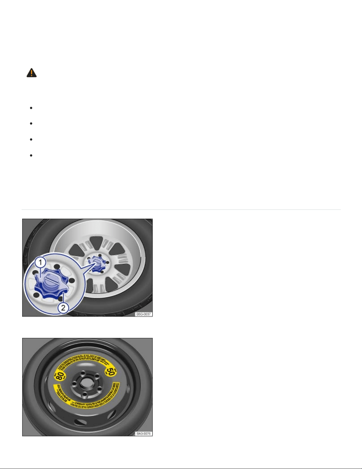
Wheel alignment: Incorrect wheel alignment causes excessive and uneven tire wear, impairing vehi‐
cle safety. If you notice excessive or uneven tire wear, have the wheel alignment checked by an au‐
thorized Volkswagen dealer or an authorized Volkswagen Service Facility.
WARNING
Unusual vibrations or pulling to one side can indicate tire damage.
Reduce speed immediately and stop when it is safe to do so.
Check tires and wheel rims for damage.
Never drive with a damaged tire or rim. Get expert assistance instead.
If no external damage is visible, slowly and carefully drive to the nearest authorized
Volkswagen dealer, authorized Volkswagen Service Facility, or other qualified workshop and
have the vehicle checked.
Compact spare wheel
Fig.189In the luggage compartment: Handwheel holding the compact spare wheel in place.
Fig.190In the luggage compartment: Compact spare wheel.

Read and follow the introductory information and safety information first⇒ Introduction to the
subject
Removing the compact spare wheel
Open the trunk lid and remove the entire luggage compartment floor from the vehicle ⇒Luggage
compartment floor – features .
If applicable: Remove the subwoofer ⇒Subwoofer .
Remove the covering over the spare wheel, being careful to remove the subwoofer wire from the
covering as well.
If applicable: Pull the securing clip ⇒Fig.189① out and up.
Completely unscrew the threaded retainer in the center of the compact spare wheel ⇒Fig.189②
counterclockwise and remove the compact spare wheel.
Stowing the replaced wheel
Open the trunk lid, lift up the entire luggage compartment floor, and slide it in the brackets on the
sides of the luggage compartment to keep it raised ⇒Luggage compartment floor – features .
If the wheel you took off the vehicle fits in the spare wheel well, position it so that the center hole
of the rim is aligned with the threaded pin in the center of the well.
Turn the handwheel ② clockwise until the wheel is securely in place.
Insert the securing clip ① (if equipped) in the stud slot so that the handwheel can no longer be
turned.
If necessary, return the vehicle tool kit to its location in the luggage compartment.
Reinstall the luggage compartment floor.
Close the trunk lid.
If the replaced wheel does not fit in the spare wheel well, stow it securely in the luggage compartment
on top of the floor covering.
Differences between the road tires and the compact spare
The compact spare is different in design from the road tires and must be used only in the event of a
flat tire, only for a brief time, and only when driving with extra caution ⇒ .
Replace it with a tire matching the others on your vehicle as soon as possible.

Please heed the following:
Do not drive faster than 50mph (80km/h)!
Avoid full-throttle acceleration, hard braking, and fast cornering!
Do not use snow chains on the compact spare wheel ⇒Snow chains .
After installing the compact spare wheel, check the tire pressure as soon as possible ⇒Tire infla‐
tion pressure .
Check the tire inflation pressure of the compact spare whenever you check the tire pressure of the
road wheels, at least once a month. Inflate a compact spare wheel to the cold tire pressure specified
for the compact spare on the tire pressure label or on a separate label for the compact spare, if there
is one.
WARNING
Improper use of a compact spare wheel can cause loss of vehicle control, a crash or other acci‐
dent, and serious personal injury.
Never use a compact spare wheel if it is damaged or worn down to the wear indicators.
In some vehicles, the compact spare wheel is smaller than the original tire. A smaller compact
spare wheel is identified with a sticker and the words 50mph or 80km/h. This is the maximum
permissible speed when driving with this tire.
Never drive faster than 50mph (80km/h) with a compact spare wheel. Avoid full-throttle accel‐
eration, heavy braking, and fast cornering!
Never drive more than 125miles (200km) if a compact spare wheel is installed.
Replace the compact spare with a normal wheel and tire as soon as possible. Compact spare
wheels are designed for brief use only.
Regularly check the U.S. DOT Tire Identification Number (TIN) to determine the age of the
compact spare wheel ⇒Tire labeling . Tires age even if they are not being used and can fail
suddenly, especially at higher speeds.
Tires that are more than 6years old can only be used in an emergency and then with special
care and at lower speeds.
The compact spare wheel must always be secured with the wheel bolts provided by the
factory.
Never drive using more than one compact spare wheel.

After installing the compact spare wheel, the tire pressure must be checked as soon as possi‐
ble ⇒Tire inflation pressure .
Snow chains cannot be used on the compact spare wheel. If you must use snow chains and
have a compact spare wheel mounted, move the compact spare wheel to the rear axle if a
front tire has to be replaced. The tire taken off the rear axle can then be used to replace the
flat front tire. Be sure you do not change the tire's direction of rotation. Install the snow chains
on the full-sized road tire.
NOTE
When the spare wheel or compact spare is being used, the TPMS indicator light can start flash‐
ing after about 10minutes ⇒Tire Pressure Monitoring System (TPMS) .
If possible, attach the compact spare wheel or the wheel you took off the vehicle securely in the
luggage compartment.
Tire labeling
Fig.191International tire labeling.

Read and follow the introductory information and safety information first⇒ Introduction to the
subject
Knowing about tire specifications makes it easier to choose the correct replacement tires. Radial tires
have specifications marked on the sidewall.
Tire labeling (example) Meaning
Brand, Logo Manufacturer
Tire name Individual tire designation of the manufacturer.
P255/55R18
Dimensions:
P Tire application: Passenger car
255 Nominal sidewall-to-sidewall width of tire in millimeters.
55 Ratio of height to width (aspect ratio)
R Tire belt design letter code for radial.
18 Rim diameter (in inches)
109H
Load rating code ⇒Load rating code and speed rating code
⇒Speed rating code letter .
XL Indicates reinforced tire (heavy-duty)
M+S or M/S Indicates Mud and Snow capability (also M/S) ⇒Winter tires .

Tire labeling (example) Meaning
RADIAL TUBELESS Tubeless radial tire.
E4...
Labeling according to international regulations (E) including
number of the approving country. The multi-digit approval num‐
ber is listed next.
DOTBTRATY51709
Tire identification number (TIN) – In some cases the manufac‐
turing date is only on one side of the tire:
DOT
The tire complies with the requirements of the United
States Department of Transportation, responsible for
issuing safety standards.
BT Identification letter of the manufacturing site.
RA Manufacturer information regarding tire dimensions.
TY5 Tire characteristics provided by the manufacturer.
1709 Manufacturing date: 17th week in 2009.
TWI
Marks the position of the treadwear indicator ⇒Tread depth
and tread wear indicators .
a)

Tire labeling (example) Meaning
Made in Germany Country of manufacture.
MAXLOAD 615KG
(1356LBS)
United States maximum load rating per wheel.
MAXINFLATION 350KPA
(51PSI)
United States maximum permissible inflation pressure.
ROTATION Rotation direction (unidirectional tires)
SIDEWALL 1PLY RAYON
Tire ply composition and materials used:
1layer of rayon.
TREAD 4PLIES
1RAYON + 2STEEL +
1NYLON
Tire tread composition and materials used:
In this example there are 4layers under the tread: 1layer of
rayon, 2layers of steel belt and 1layer of nylon.
Consumer information regarding comparison to specified base tires (standardized test pro‐
cedure)⇒ ⇒UTQG classification :

91
92
93
95
97
Tire labeling (example) Meaning
TREADWEAR220
Relative service life expectancy of the tire referenced to a U.S.-
specific standard test.
TRACTIONA Traction rating under wet conditions (AA, A, B or C).
TEMPERATUREA
Temperature stability of the tire at increased test bench speeds
(A, B or C).
Additional numbers found on the tire could either be tire manufacturer internal labels or
country-specific labels (such as for Brazil and China).
Unidirectional tires
Unidirectional tires are designed to rotate only in one direction. Unidirectional tires have arrows on the
sidewalls that show the direction of rotation. Make sure you mount the tire so that it rotates in the
proper direction. The tire's performance with regard to hydroplaning, traction, noise, and wear is
worse if it is not mounted in the proper direction of rotation.
If you have to mount a tire opposite to its proper direction of rotation, you must drive more carefully,
since the tire is no longer being used as designed. This is particularly important on wet roads. You
must replace or remount the tire as soon as possible in order to restore the correct direction of
rotation.
Load rating code
The load index indicates the maximum permissible load per individual tire in pounds (kilograms).
1356lbs (615kg)
1388lbs (630kg)
1433lbs (650kg)
1521lbs (690kg)
1609lbs (730kg)

98
99
100
101
102
103
104
110
P
Q
R
S
T
U
H
V
W
Y
Z
1653lbs (750kg)
1709lbs (775kg)
1763lbs (800kg)
1819lbs (825kg)
1874lbs (850kg)
1929lbs (875kg)
1984lbs (900kg)
2337lbs (1060kg)
Speed rating code letter
The speed rating code letter indicates the maximum permissible road speed of the tires.
up to93mph (150km/h)
up to99mph (160km/h)
up to106mph (170km/h)
up to112mph (180km/h)
up to118mph (190km/h)
up to124mph (200km/h)
up to130mph (210km/h)
up to149mph (240km/h)
up to168mph (270km/h)
up to186mph (300km/h)
over149mph (240km/h)
Some tire manufacturers label tires with a maximum permissible road speed above 149mph
(240km/h) with the letter combination ZR.
WARNING
Using incorrect or unmatched tires and/or wheels or improper tire and wheel combinations can
lead to loss of control, collision and serious personal injury.
Always use tires, wheels and wheel bolts that meet the specifications of the original factory-
installed tires or other combinations that have been specifically approved by the vehicle
manufacturer.

All 4wheels must be fitted with radial tires of the same type, the same size (tread circumfer‐
ence), and the same tread pattern. Driving with different tires reduces vehicle handling and
can lead to a loss of control.
Never drive faster than the maximum speed for which the tires installed on your vehicle are
rated because tires that are driven faster than their rated speed can fail suddenly.
Overloading tires can cause heat build-up, sudden tire failure, including a blowout and sudden
deflation and loss of control.
Temperature grades apply to tires that are properly inflated and not over- or underinflated.
TIN represents the serial number of the tire.
Winter tires
Read and follow the introductory information and safety information first⇒ Introduction to the
subject
Winter tires improve the handling characteristics of your vehicle significantly when driving under win‐
try road conditions. Summer tires have less traction on snow and ice because of their design (width,
rubber composition, tread design). Volkswagen strongly recommends that you always have winter
tires or all-season tires installed on all 4wheels on your vehicle, especially when winter road condi‐
tions are expected. Winter tires also improve the vehicle's braking performance and help reduce stop‐
ping distances during winter weather. Volkswagen recommends installing winter tires once tempera‐
tures are below +45°F (+7°C).
Winter tires are no longer suitable for winter driving once the tread pattern is worn down to a depth
of 3/16in (4.8mm). In addition, winter tire performance decreases with age – independent of the
tread profile depth.
When using winter tires:
Obey state and country-specific legal requirements.
Install winter tires on all 4wheels.
Use winter tires only under wintry road conditions.
Only use winter tires with dimensions approved for the vehicle.
Use only winter tires of the same tire belt design, the same dimensions (tread circumference), and
the same tread design.
a)

Follow speed restrictions according to the winter tire's speed rating code letter ⇒ .
Speed restrictions
Winter tires are certified up to a top speed identified by speed rating code letters on the sidewall
⇒Tire labeling .
In appropriately equipped vehicles, the speed warning can be set and changed in the Vehicle set‐
tings menu in the Infotainment system.
Top speed rating and tire inflation pressure for V winter tires depend on the engine installed in your
vehicle. Be sure to ask your authorized Volkswagen dealer or authorized Volkswagen Service Facility
about the maximum permissible speed and the required tire inflation pressure for the winter tires that
you plan to use.
All-wheel drive (4MOTION)
Vehicles with all-wheel drive and standard road wheels have good forward motion and traction even
under wintry road conditions. However, Volkswagen recommends installing winter tires or all season
tires on all 4wheels to improve handling as well as braking performance.
If you use snow chains, please read and heed information and directions ⇒Snow chains .
WARNING
Driving faster than the maximum speed for which the winter tires on your vehicle were designed
can cause sudden tire failure including a blowout and sudden deflation, loss of control, crashes
and serious personal injuries.
Winter tires have a maximum speed rating that may be lower than your vehicle's maximum
speed.
Never drive faster than the maximum speed for which the winter tires installed on your vehicle
are rated because tires that are driven faster than their rated speed can fail suddenly.
Never exceed the maximum load rating for the winter tires installed on your vehicle.
Install summer tires promptly in the spring. Summer tires offer better handling characteristics for
temperatures above +45°F (+7°C). They are quieter, do not wear as quickly, and reduce fuel
consumption.

The Tire Pressure Monitoring System must be recalibrated whenever you remove and remount or
change any wheel or tire on the vehicle, even if the reinstalled or replacement wheels and tires
are identical to those that were removed and even if the tire pressure does not change ⇒Tire
Pressure Monitoring System (TPMS) .
If necessary, ask your authorized Volkswagen dealer or authorized Volkswagen Service Facility
about permissible winter tire dimensions.
Snow chains
Read and follow the introductory information and safety information first⇒ Introduction to the
subject
Obey local regulations as well as the applicable speed limits when driving with snow chains.
Snow chains improve forward motion, traction and braking characteristics under wintry conditions.
Snow chains may be used only on the front wheels and only on the following tire and wheel combi‐
nations that have been approved by Volkswagen. This applies even to all-wheel drive vehicles
(4MOTION).
Tire size Rim
245/65 R17 7,5 J x 17 ET 31
Please contact your authorized Volkswagen dealer or authorized Volkswagen Service Facility about
appropriate wheel, tire and snow chain dimensions.
If possible, use only chains with low profile links that are not thicker than 19/32in. (13.5mm) includ‐
ing the tensioner.
Remove center hubcaps and decorative rim rings before installing snow chains ⇒ . However, for
safety reasons, caps must be installed on the wheel bolts. These are available from authorized
Volkswagen dealers and authorized Volkswagen Service Facilities.
Compact spare wheel

For technical reasons, snow chains cannot be used on the compact spare wheel ⇒Compact spare
wheel .
If you must use snow chains and have a compact spare wheel mounted, move the compact spare
wheel to the rear axle if a front tire has to be replaced. The tire taken off the rear axle can then be
used to replace the flat front tire. Be sure to install the unidirectional tires so that they will run in the
proper direction. Volkswagen recommends installing the snow chains before mounting the wheel to
the vehicle.
WARNING
Using the wrong snow chains or installing snow chains improperly can cause accidents and se‐
vere personal injuries.
Always use the proper snow chains.
Follow the installation instructions provided by the snow chain manufacturer.
Never exceed the permissible speed limit when driving with snow chains.
NOTE
Remove snow chains when roads are free of snow. Otherwise, the chains can damage the
tires, impair vehicle handling and can be quickly worn down.
Snow chains can scratch or damage wheel rims if they have direct contact with the rims.
Volkswagen recommends using coated snow chains.
Glossary of tire and loading terminology
Read and follow the introductory information and safety information first⇒ Introduction to the
subject
Accessory weight
The combined weight (in excess of those standard items which may be replaced) of automatic trans‐
mission, electro-mechanical power steering, power brakes, power windows, power seats, radio, and
heater, to the extent that these items are available as factory-installed equipment (whether installed or
not).
Aspect ratio

The ratio of sidewall height to tire width, expressed as a percentage. A number of 50 (0.5:1 or 50%)
means that the cross-sectional height is 50% of the tread width. A shorter sidewall can improve steer‐
ing response and provide better overall handling, for example, on dry pavement.
Bead
The part of a tire made of steel wires, wrapped or reinforced by ply cords, with the shape and struc‐
ture to ensure proper fit to the wheel rim.
Bead separation
A breakdown of the bond between components in the bead.
Carcass
The tire structure, except tread and sidewall rubber which, when inflated, bears the load.
Chunking
The breaking away of pieces of the tread or sidewall.
Cord
The strands of material forming the plies in the tire.
Cord separation
The parting of cords from adjacent rubber compounds.
Cracking
Any parting within the tread, sidewall, or inner liner of the tire extending to cord material.
Cold tire inflation pressure
The tire pressure recommended by the vehicle manufacturer for a tire of a specified size that has not
been driven for more than a couple of miles (kilometers) at low speeds in the 3hour period before the
tire pressure is measured or adjusted.
Curb weight
The weight of a motor vehicle with standard equipment including the maximum capacity of fuel, oil,
and coolant, air conditioner, and additional weight of optional equipment.
Extra load tire

A tire designed to operate at higher loads and at higher inflation pressures than the corresponding
standard tire.
Gross Axle Weight Rating (GAWR)
The load-carrying capacity of a single axle system, measured where the tire contacts the ground.
Gross Vehicle Weight Rating (GVWR)
The maximum loaded weight of the vehicle.
Groove
The space between 2adjacent tread ribs.
Load rating (code)
The maximum load that a tire is rated to carry for a given inflation pressure. You may not find this in‐
formation on all tires because it is not required by law.
Maximum load rating
The load rating for a tire at the maximum permissible inflation pressure for that tire.
Maximum loaded vehicle weight
The total of:
Curb weight.
Accessory weight.
Vehicle capacity weight.
Production options weight.
Maximum (permissible) inflation pressure
The maximum cold inflation pressure to which a tire may be inflated. Also called maximum inflation
pressure.
Normal occupant weight
Means 150lbs (68kilograms) times the number of occupants seated in the vehicle up to the total
seating capacity of your vehicle.

Occupant distribution
The placement of passengers in a vehicle.
Outer diameter
The diameter of a new, properly inflated tire.
Overall width
Total width measured at the exterior sidewalls of an inflated tire, including the additional width of la‐
beling, decorations, or protective bands or ribs.
Passenger car tire
A tire intended for use on passenger cars, multipurpose passenger vehicles, and trucks, that have a
gross vehicle weight rating (GVWR) of 10,000pounds or less.
Ply
A layer of rubber-coated parallel cords.
Ply separation
A parting of rubber compound between adjacent plies.
Pneumatic tire
A mechanical device made of rubber, chemicals, fabric, and steel or other materials, that, when
mounted on an automotive wheel, provides the traction and contains the gas or fluid that sustains the
load.
Production options weight
The combined weight of installed regular production options weighing over 5lbs (2.3kg) more than
the standard items they replace, and not previously considered as curb weight or accessory weight.
These include, for example, heavy-duty brakes, ride levelers, roof rack, heavy-duty battery, and spe‐
cial trim.
Radial ply tires
A pneumatic tire in which the ply cords that extend to the beads are laid at substantially 90degrees to
the centerline of the tread.
Recommended inflation pressure

The tire pressure recommended by the vehicle manufacturer for a tire of a specified size that has not
been driven for more than a couple of miles (kilometers) at low speeds in the 3hour period before the
tire pressure is measured or adjusted.
Reinforced tire
A tire designed to operate at higher loads and at higher inflation pressures than the corresponding
standard tire.
Rim
The outer edge of a wheel upon which the tire beads are seated.
Rim diameter
The nominal diameter of the wheel's tire bead seating surface. If you change your wheel size, to
wheels of a different diameter, you will have to purchase new tires to match the new wheels.
Rim size
Designation means rim diameter and width.
Rim type designation
The industry or manufacturer's designation for a rim by style or code.
Rim width
The nominal distance between wheel rim flanges.
Section width
The linear distance between the exteriors of the sidewalls of an inflated tire, excluding elevations due
to labeling decoration, or protective bands.
Sidewall
The portion of a tire between the bead and the tread.
Sidewall separation
The parting of the rubber compound from the cord material in the sidewall.
Speed rating (letter code)

A standardized letter code indicating the maximum speed at which a tire is designed to be driven for
extended periods of time. The ratings range from 93mph (150km/h) P to 186mph (300km/h) Y.
The speed rating letter code, where applicable, is molded on the tire sidewall ⇒Tire labeling . You
may not find this information on all tires because it is not required by law.
Tire Pressure Monitoring System
A system that detects when at least one of a vehicle's tires is underinflated and illuminates a low tire-
pressure warning light.
Tread
The portion of a tire that normally touches the road.
Tread rib
A tread section running circumferentially around a tire.
Tread separation
Tire failure caused by the tread pulling away from the tire carcass.
Tread wear indicators (TWI)
Raised areas within the main tread grooves that show, visually, when tires are worn and near the end
of their useful life ⇒Tread depth and tread wear indicators .
Uniform Tire Quality Grading (UTQG)
A tire information system developed by the U.S. National Highway Traffic Safety Administration
(NHTSA) that is designed to help buyers compare tires. UTQG is not a safety rating, nor is it a guar‐
antee that a tire will last for a certain number of miles or perform a certain way. It gives tire buyers
more information to compare with factors such as price, brand loyalty and dealer recommendations.
Under UTQG, tires are graded by the tire manufacturers in 3areas: tread wear, traction and tempera‐
ture resistance. UTQG information is molded into the tire sidewalls.
U.S. DOT Tire Identification Number (TIN)
A tire's serial number. It begins with the letters DOT (Department of Transportation) and indicates that
the tire meets all federal standards. The next 2numbers or letters indicate the plant where the tire
was manufactured. The last 4numbers represent the week and year of manufacture.

For example, the numbers 1709mean that the tire was produced in the 17th week of 2009. Any other
numbers are marketing codes used by the tire manufacturer. This information is used to help identify
affected consumers if a tire defect requires a recall.
Vehicle capacity weight
The total rated cargo, luggage and passenger load. Passenger load is 150lbs (68kilograms) times
the vehicle's total seating capacity (as listed on the label inside the driver door).
Vehicle maximum load on the tire
The load on an individual tire that is determined by taking each axle's share of the maximum loaded
vehicle weight (GAWR) and dividing by2.
Vehicle normal load on the tire
The load on an individual tire that is determined by taking each axle's share of the curb weight, acces‐
sory weight, and normal occupant weight (distributed according to the table below) and dividing by2.
Wheel size designation
Wheel rim diameter and width.
Occupant loading and distribution for vehicle normal load for various designated seating capacities
Designated seating capacity,
number of occupants
Vehicle normal load, number
of occupants
Occupant distribution in a nor‐
mally loaded vehicle
2, 3, or 4 2 2in front
5, 6, or 7 3 2in front, 1in back
Tires and vehicle load limits
Read and follow the introductory information and safety information first⇒ Introduction to the
subject
There are limits to the load any vehicle or any tire can carry. A vehicle that is overloaded will not han‐
dle well and is more difficult to stop. Overloading can damage important parts of the vehicle.
Overloading can also lead to blowout, sudden loss of pressure or other tire failure that can cause loss

of control.
Your safety and the safety of your passengers depends on making sure that load limits are not ex‐
ceeded. Vehicle load includes everybody and everything in and on the vehicle. These load limits are
technically referred to as the vehicle's Gross Vehicle Weight Rating (GVWR).
The GVWR includes the weight of the basic vehicle, all factory-installed and other accessories, a full
tank of fuel, oil, coolant and other fluids plus maximum load. The maximum load includes the number
of passengers that the vehicle is intended to carry (seating capacity) with an assumed weight of
150lbs (68kg) for each passenger at a designated seating position and the total weight of any lug‐
gage in the vehicle. If you tow a trailer, the weight of the trailer hitch and the tongue weight of the
loaded trailer must be included as part of the vehicle weight. At altitudes above 3000ft (1000m),
combined towing weight (vehicle plus trailer) must be reduced by 10% for every 3000ft (1000m).
The Gross Axle Weight Rating (GAWR) is the maximum load that can be carried at each of the
vehicle's 2axles (by the front or rear tires). GVWR and GAWR are listed on the safety compliance la‐
bel on the driver door jamb. Your vehicle has either 6total seating positions (2in the front, 2 in the
middle, and 2in back) or 7 total seating positions (2in the front, 3 in the middle, and 2in back). Each
seating position has a safety belt. Because there is an upper limit to your vehicle's total weight
(GVWR), the weight of whatever is being carried (including the weight of a trailer hitch and the tongue
weight of the loaded trailer) is also limited. More passengers, or passengers who are heavier than the
assumed 150lbs (68kg), mean that less weight can be carried as luggage or other cargo. The tire
pressure label on your Volkswagen also lists the maximum combined weight of all of the occupants
and luggage or other cargo that the vehicle can carry.
WARNING
Overloading a vehicle can cause loss of vehicle control, a crash or other accident, serious per‐
sonal injury, and even death.
Carrying more weight than your vehicle was designed to carry will prevent the vehicle from
handling properly and increase the risk of the loss of vehicle control.
The brakes on a vehicle that has been overloaded may not be able to stop the vehicle in a
safe distance.
Tires on a vehicle that has been overloaded can fail suddenly, including a blowout and sudden
deflation, causing loss of control and a crash.
Always make sure that the total load being transported - including the weight of a trailer hitch
and the tongue weight of a loaded trailer - does not make the vehicle heavier than the

vehicle's Gross Vehicle Weight Rating.
Determining the correct load limit
Read and follow the introductory information and safety information first⇒ Introduction to the
subject
Never overload tires. The following example illustrates how to determine the combined weight of all
vehicle occupants and luggage or other vehicle payloads. Never overload the vehicle!
Steps for Determining Correct Load Limit:
1.
Locate the statement THE COMBINED WEIGHT OF OCCUPANTS AND CARGO SHOULD
NEVER EXCEED XXX KG OR XXX LBS on your vehicle's placard (tire inflation pressure
label) ⇒Tire inflation pressure .
2.
Determine the combined weight of the driver and passengers that will be riding in your
vehicle.
3. Subtract the combined weight of the driver and passengers from XXX kg or XXX lbs.
4.
The resulting figure equals the available amount of cargo and luggage load capacity.
For example, if the XXX amount equals 1400lbs. and there will be five 150lb. passengers
in your vehicle, the amount of available cargo and luggage load capacity is 650lbs.(1400-
750 (5x 150)= 650lbs.)

Steps for Determining Correct Load Limit:
5.
Determine the combined weight of luggage and cargo being loaded on the vehicle. That
weight may not safely exceed the available cargo and luggage load capacity calculated in
Step4.
6.
If your vehicle is capable of towing a trailer: The load from your trailer will be transferred to
your vehicle. Consult this manual to determine how this reduces the available cargo and
luggage load capacity of your vehicle.
Check the tire sidewall to determine the load index specified for the tire.
UTQG classification
Read and follow the introductory information and safety information first⇒ Introduction to the
subject
Uniform Tire Quality Grading (UTQG): Quality grades can be found where applicable on the tire side‐
wall between the tread shoulder and maximum section width. Example:
Treadwear(number)
Traction:AA, A, B or C
Temperature:A, B or C
For example: Treadwear200, TractionAA, TemperatureA.
All passenger car tires must conform to Federal Safety Requirements in addition to these grades.
Treadwear
The treadwear grade is a comparative rating based on the wear rate of the tire when tested under
controlled conditions on a specified government test course.

For example, a tire graded 150 (Treadwear-value 150) would wear one-and-one-half (11/2) times as
well on the government course as a tire graded 100.
The relative performance of tires depends upon the actual conditions of their use, however, and may
depart significantly from the norm due to variations in driving habits, service practices and differences
in road characteristics and climate.
Traction
The traction grades, from highest to lowest, are AA, A, B, and C. Those grades represent the tire's
ability to stop on wet pavement as measured under controlled conditions on specified government
test surfaces of asphalt and concrete. A tire marked C may have poor traction performance ⇒ .
Temperature
The temperature grades are A (the highest), B, and C representing the tire's resistance to the genera‐
tion of heat, and its ability to dissipate heat when tested under controlled conditions on a specified in‐
door laboratory test wheel.
Sustained high temperature can cause the material of the tire to degenerate and reduce tire life, and
excessive temperature can lead to sudden tire failure.
The grade C corresponds to a level of performance which all passenger car tires must meet under the
Federal Motor Vehicle Safety Standard No.109. Grades B and A represent higher levels of perfor‐
mance on the laboratory test wheel than the minimum required by law ⇒ .
WARNING
The traction grade assigned to this tire is based on straight-ahead braking traction tests, and
does not include acceleration, cornering, hydroplaning or peak traction characteristics.
WARNING
The temperature grade for this tire is established for a tire that is properly inflated and not over‐
loaded. Excessive speed, underinflation or excessive loading, either separately or in combination,
can cause heat buildup and possible tire failure.
Wheel trim
Hubcaps
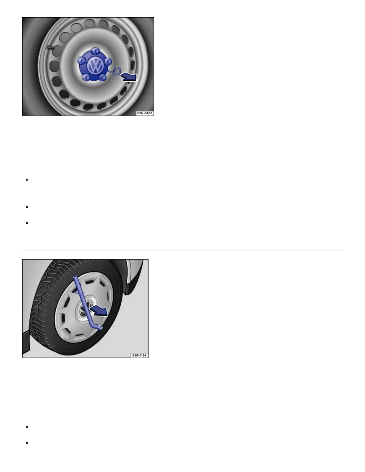
Fig.192Pulling the hubcap off.
The hubcaps are designed to protect the wheel bolts and should be installed again after the wheel
change.
To remove Take the wire clip out of vehicle tool kit and hook it into one of the holes in the hubcap
⇒Fig.192 .
Pull the hubcap off in the direction of the arrow.
To install Press the hubcap against the rim until it latches.
Wheel covers
Fig.193Pulling the wheel cover off.
The wheel cover protects the wheel bolts and must be installed again after changing the wheel.
Pulling off the wheel cover
Take the lug wrench and wire clip out of the vehicle tool kit ⇒Vehicle tool kit .
Place the wire clip hook in one of the openings of the wheel cover.
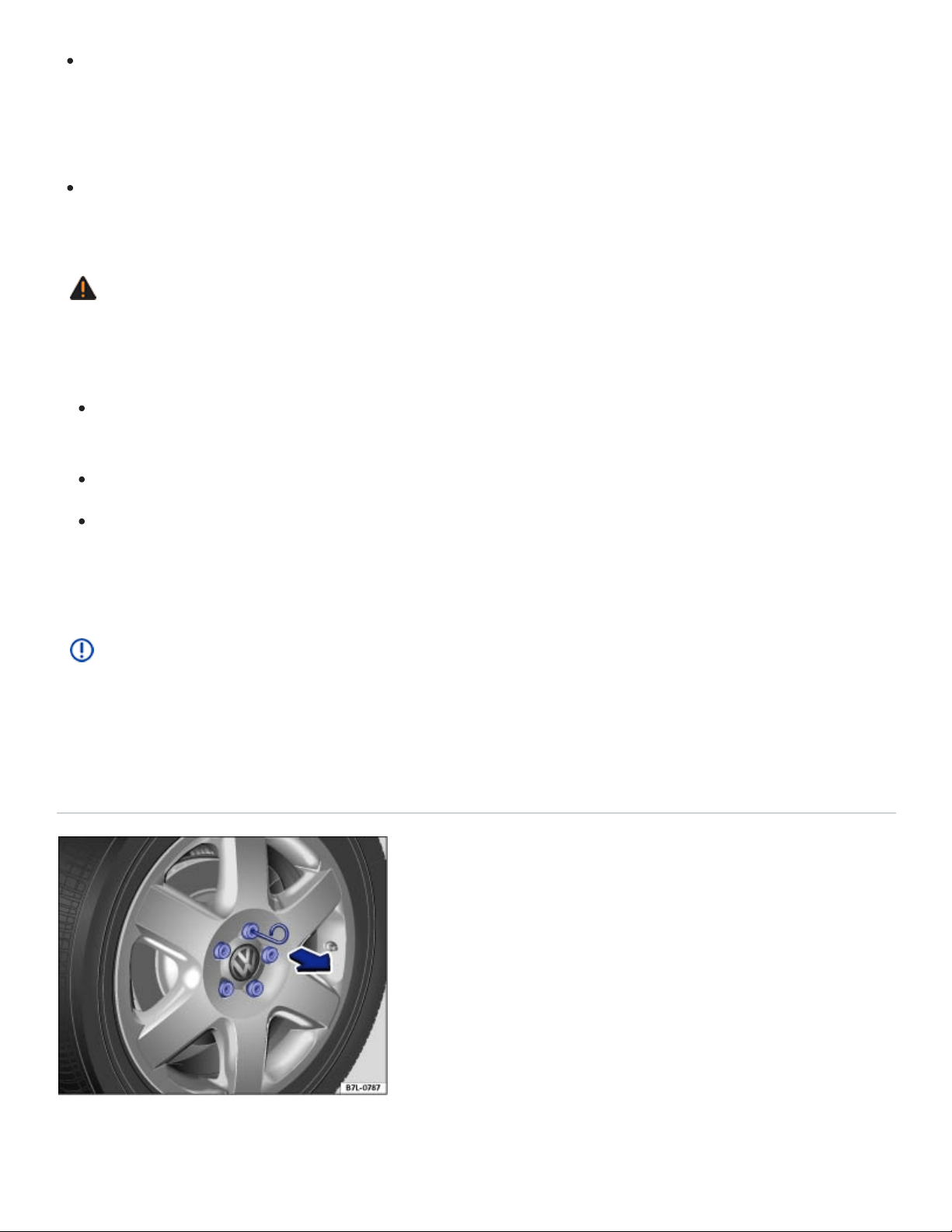
Slide the lug wrench through the clip ⇒Fig.193 and pull the wheel cover off in the direction of the
arrow.
Installing the wheel cover
Align the valve cutout with the valve and press the wheel cover onto the wheel rim.
Make sure that the wheel cover is latched onto the rim along the entire circumference.
WARNING
Unsuitable wheel covers and improper installation of wheel covers can cause accidents and se‐
vere injuries.
Improperly installed wheel covers can come loose while driving and endanger other motorists
and cyclists.
Do not use damaged wheel covers.
Always make sure that the flow of air for brake system cooling is not blocked or reduced be‐
fore installing wheel covers. This applies to both factory-installed wheel covers and aftermar‐
ket wheel covers. Insufficient air supply may significantly increase stopping distance.
NOTE
To help prevent damage to the vehicle, be careful when removing wheel covers and be sure to
install them properly.
Wheel bolt caps
Fig.194Pulling cover caps off wheel bolts.

Take the wire clip out of the vehicle tool kit ⇒Vehicle tool kit .
Insert the wire clip through the opening of the cover cap ⇒Fig.194 and pull off in the direction of
the arrow.
The caps are designed to protect the wheel bolts and should be installed again after the wheel
change.
Changing a wheel
Introduction to the subject
In this chapter you will find information on the following subjects:
⇒Preparations for changing a wheel
⇒Wheel bolts
⇒Lifting the vehicle with the vehicle jack
⇒Changing a wheel
⇒After changing a wheel
Change a wheel by yourself only if the vehicle is parked in a safe location, you are familiar with safety
procedures and the technical steps, and you have proper tools available. Otherwise, get expert
assistance.
The vehicle jack can only be safely used to change the wheel on a vehicle that has only one flat or
damaged tire. If the vehicle does not have the support it needs from 3fully inflated tires, the vehicle
can fall off the jack. If more than 1tire on the vehicle is flat or damaged, do not lift the vehicle with the
vehicle jack. Instead, get expert assistance.
WARNING
Changing a wheel, especially on the side of the road, can be dangerous. To help reduce the risk
of serious personal injury:
Always stop the vehicle as soon as it is safe to do so. Move the vehicle a safe distance off the
road where it is safe to change the wheel.

Always make sure that all passengers, especially children, are in a safe place outside the vehi‐
cle and away from the vehicle and traffic (such as behind a guard rail).
Turn on the emergency flashers and set up another warning device about 25yards
(25meters) behind the vehicle to warn approaching traffic.
Change a wheel by yourself only if you are familiar with the necessary steps. Otherwise, get
expert assistance.
Always make sure that the ground is level and firm. If necessary, place the jack on a large and
sturdy board or on a similar ground support.
Always use proper and undamaged tools when changing a wheel.
Never loosen the screws on rims with threaded rim rings.
After changing a wheel, check the wheel bolt tightening torque checked with an accurate
torque wrench.
Always use a jack that has been approved by the manufacturer for your vehicle. Never use
other jacks, even if they have been approved for use on other Volkswagen models.
WARNING
Sudden vehicle movement when changing a tire can cause the vehicle to slip off the jack and
cause serious personal injury. Only placing the transmission in Park (P) will not prevent the vehi‐
cle from moving suddenly when one wheel is off the ground. Before raising the vehicle:
Always shift the transmission to Park (P), firmly apply the parking brake, stop the engine, and
remove the key from the vehicle.
Always block the wheel diagonally opposite the wheel being changed with chocks or other
similar things.
Preparations for changing a wheel
Read and follow the introductory information and safety information first⇒ Introduction to the
subject
Checklist
Getting ready to change a wheel. Follow these steps in the order listed here ⇒ :

If you have a flat tire, move as far away from traffic as possible. Park the vehicle on a flat and
level surface where no part of the hot catalytic converter and exhaust system can come into contact
with flammable materials under the vehicle, such as dry grass, brush, spilled fuel, etc.
Switch on the emergency flashers to warn oncoming traffic In an emergency. Observe all legal
requirements.
Shift the transmission into Park (P) Automatic transmission.
Set the parking brake to help prevent the vehicle from moving Electronic parking brake.
Stop the engine and remove the key from the ignition switch or turn off the ignition with the
starter button and remove the key from the vehicle Starting and stopping the engine.
Have all passengers exit and go to a safe place, such as behind a guard rail.
Block the diagonally opposite wheel with chocks or other suitable things.
If towing a trailer: Unhitch the trailer from the vehicle and park the trailer properly.
If the luggage compartment is loaded: Remove the luggage.
Raise and secure the luggage compartment floor.
If applicable: Remove the subwoofer Subwoofer.
Unscrew the fastening screw with washer counterclockwise and remove.
Take the spare or compact spare wheel and the vehicle tool kit out of the luggage
compartment.
Take off the wheel covers Wheel trim.
WARNING
Disregarding the safety-related checklist may lead to accidents and serious personal injuries.
Always review and follow the checklist. Follow accepted safety practices and use common
sense.
Wheel bolts
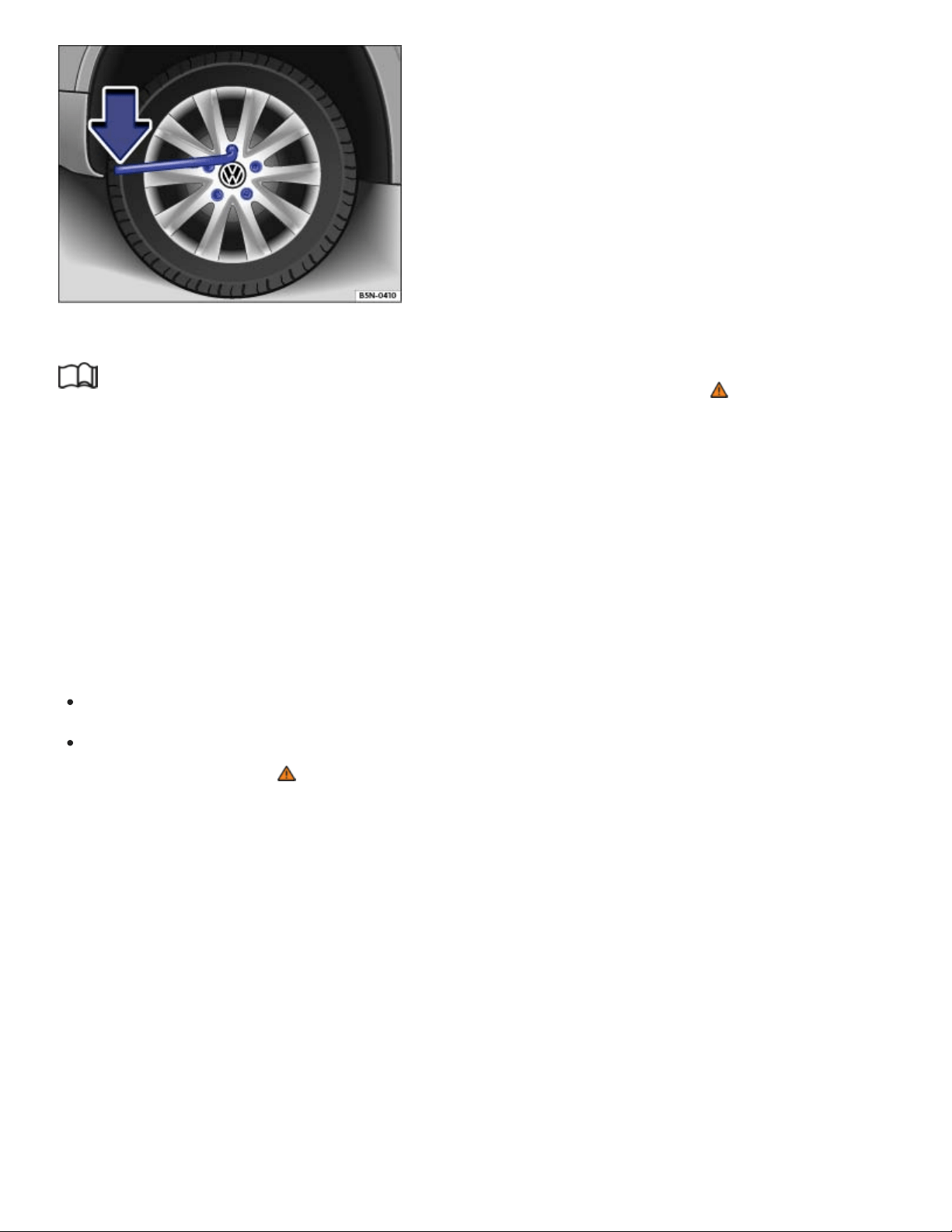
Fig.195Changing a wheel: Loosening the wheel bolts.
Read and follow the introductory information and safety information first⇒ Introduction to the
subject
Loosen the wheel bolts only with the lug wrench that was produced by Volkswagen for your vehicle.
Loosen the wheel bolts only about 1turn before lifting the vehicle with the jack.
If a wheel bolt does not come loose, carefully push the end of the lug wrench with your foot. Make
sure you are standing firmly on the ground and hold on to the vehicle for support.
Loosening the wheel bolts
Push the lug wrench over the wheel bolt all the way ⇒Fig.195 .
Holding the lug wrench at the end, loosen the wheel bolt by turning it counterclockwise about1
complete turn (360°) ⇒ .
Important information regarding wheel bolts
The design of rims and wheel bolts is matched to the factory-installed wheels.
The designated wheel bolts for your vehicle are two-piece wheel bolts with a rotating shoulder.
Regular one-piece wheel bolts must not be used on your vehicle. If you are unsure about the correct
wheel bolts to be used on your vehicle, please contact an authorized Volkswagen dealer or an autho‐
rized Volkswagen Service Facility.
If different wheels are installed, wheel bolts with the right length and bolt head shape must be used.
The attachment of the wheels and function of the brake system depend on this.
It may not be possible to use wheel bolts from different vehicles of the same model.

Wheel bolt tightening torque
Correctly tightened bolts for steel and alloy wheel rims should have a torque of 88ft-lbs (120Nm).
After changing a wheel, have the wheel bolt tightening torque checked right away with an accurate
torque wrench.
Before you check the tightening torque, replace corroded and difficult-to-turn wheel bolts and clean
the threads in the wheel hub.
Never grease or oil the wheel bolts and the threads in the wheel hubs. The bolts can come loose
while driving if greased or oiled, even if tightened to the required torque.
WARNING
Improperly tightened wheel bolts can come loose while driving and cause you to lose control over
the vehicle, resulting in accidents and serious injuries.
Only use two-piece wheel bolts that belong to your vehicle and to the wheel being installed.
Never use different wheel bolts.
Wheel bolts and wheel hub threads must always be clean, easy-to-turn and free of oil and
grease.
Only use the lug wrench produced by Volkswagen for your vehicle to loosen the wheel bolts.
Loosen the wheel bolts only about 1turn before lifting the vehicle with the jack.
Never grease or oil the wheel bolts and the threads in the wheel hubs. The bolts can come
loose while driving if greased or oiled, even if tightened to the required torque.
Never loosen bolted connections on wheel rims with bolted rim rings.
If the wheel bolts are not tightened to the proper torque, the wheel can come off the vehicle
when it is moving. Extremely high torque can damage the wheel bolts and/or their threads.
Regularly check the torque with a torque wrench.
Lifting the vehicle with the vehicle jack
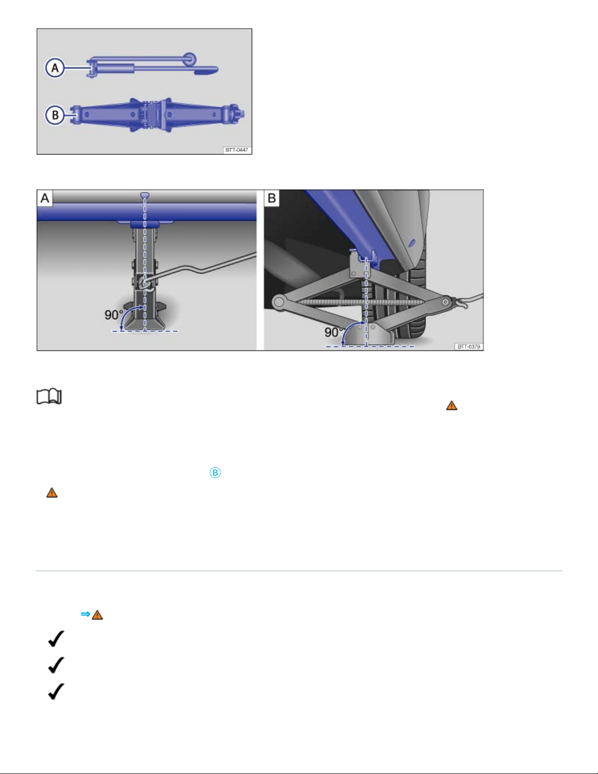
Fig.196Components of the vehicle jack.
Fig.197Jack in position at the left rear lift point.
Read and follow the introductory information and safety information first⇒ Introduction to the
subject
The jack must be positioned at one of the 4lift points behind the markings on the vehicle body (2on
each side as shown in ⇒Fig.197
Ⓑ
). You must use the lift point closest to the wheel being changed
⇒ .
The vehicle may only be lifted by a jack positioned at one of the 4jack lift points.
Checklist
For your own safety and that of your passengers, carry out the following steps in the order
listed ⇒ :
Find a level spot on firm ground for lifting the vehicle.
Straighten the steering wheel so that the front wheels point straight forward.
Shift the transmission into Park (P)) Automatic transmission selector lever.

Apply the electronic parking brake to help prevent the vehicle from moving Electronic parking
brake.
Stop the engine and remove the key from the ignition switch or turn off the ignition with the
starter button and remove the key from the vehicle Starting and stopping the engine.
If towing a trailer: Unhitch the trailer from the vehicle and park the trailer properly.
Block the diagonally opposite wheel with chocks or other suitable things.
Loosen the wheel bolts of the wheel to be changed Changing a wheel.
Find the jack lift point on the vehicle frame that is closest to the wheel to be changed Side
view.
Insert the crank
Ⓐ
into the opening on the vehicle jack
Ⓑ
.
Crank up the jack so that it still just fits underneath the lift point.
Position the jack so that its base is directly underneath the lift point , making sure that the en‐
tire base of the jack rests securely on the ground.
Align the jack and wind up the jack claw at the same time, until the claw cradles the vertical rib
underneath the vehicle .
Continue cranking up the jack until the wheel is just a little off the ground.
WARNING
Improper use of your vehicle jack can cause the vehicle to fall off the jack leading to serious per‐
sonal injury. To help reduce the risk of serious personal injury:
Use only jacks approved by Volkswagen for the vehicle. Other jacks might slip, even those ap‐
proved for other Volkswagen models, but not for your vehicle.
Always set up the jack on firm and level ground. The vehicle may slip off the jack if the jack is
resting on soft or sloping ground. If necessary, place a sturdy board under the jack.
On a hard, slippery surface (such as a tiled floor), use an anti-skid rubber mat or something
similar to help prevent the jack from slipping.
Position the jack only at the described vehicle lift points. Before you raise your vehicle, always
make sure the jack claw properly grips the vertical rib under the sill so that the jack does not
slip off when you are raising the vehicle ⇒Fig.197 .
Never have any part of your body (such as your arm or leg) under the vehicle when it is sup‐
ported by the jack. Never let other persons have any part of their body under the vehicle,

either!
If you must work under a vehicle raised on a floor jack, always make sure that the vehicle is
safely supported on safety stands intended for that purpose that are strong enough to support
the weight of the vehicle.
Never lift the vehicle when it is tilted or inclined to one side or the engine is running.
Never lift the vehicle when more than 1tire is flat or damaged.
Do not start the engine while the vehicle is supported by a jack. Engine vibrations may cause
the vehicle to slip off the jack.
WARNING
Disregarding the safety-related checklist may lead to accidents and serious personal injuries.
Always review and follow the checklist. Follow accepted safety practices and use common
sense.
Changing a wheel
Fig.198Changing a wheel: Remove previously loosened wheel bolts using the screwdriver handle.
Read and follow the introductory information and safety information first⇒ Introduction to the
subject
Removing the wheel
Review the checklist ⇒Preparations for changing a wheel .
Loosen the wheel bolts ⇒Wheel bolts .
Lift the vehicle ⇒Lifting the vehicle with the vehicle jack .

Completely unscrew and remove the previously loosened wheel bolts using the hexagonal socket
in the screwdriver handle ⇒Fig.198 . Place the wheel bolts on a clean surface.
Remove the wheel.
Mounting a compact spare wheel
If the tire is a unidirectional tire, be sure to install it in the proper rolling direction ⇒Tire labeling .
Place the compact spare wheel on the axle.
Screw in the wheel bolts clockwise and tighten them slightly using the hexagonal socket in the
screwdriver handle.
Lower the vehicle with the jack.
Use the lug wrench to firmly tighten all wheel bolts (turn clockwise) ⇒ . Do not tighten them in
sequence! Tighten any wheel bolt to begin, then tighten the wheel bolt diagonally opposite the first
bolt, and so forth.
Install the wheel bolt caps, center wheel hubcap, or wheel cover, if any ⇒Wheel trim .
WARNING
Wheel bolts that are tightened or installed improperly can come loose, causing loss of vehicle
control, a crash, and serious personal injury.
Always keep wheel bolts and threads in the wheel hub clean and free of oil and grease. The
wheel bolts must turn easily and must be tightened with the right torque.
Use the hexagonal socket in the screwdriver handle only to turn the wheel bolts when they are
loose, never to loosen them or tighten them firmly.
WARNING
Improper use of a compact spare wheel can cause loss of vehicle control, a crash or other acci‐
dent, and serious personal injury.
Never use a compact spare wheel if it is damaged or worn down to the wear indicators.
Never drive faster than 50mph (80km/h) with a compact spare wheel. Avoid full-throttle accel‐
eration, heavy braking, and fast cornering!
Never drive more than 125miles (200km) if a compact spare wheel is installed.

Replace the compact spare with a normal wheel and tire as soon as possible. Compact spare
tires are designed for brief use only.
After changing a wheel
Read and follow the introductory information and safety information first⇒ Introduction to the
subject
Clean the tools in the vehicle tool kit if necessary and stow them in the foam insert in the luggage
compartment ⇒Vehicle tool kit .
Securely store the compact spare wheel or the wheel you took off the vehicle in the luggage
compartment.
Have the wheel bolt tightening torque immediately checked with a torque wrench ⇒Wheel bolts .
Have the damaged wheel replaced as soon as possible.
The Tire Pressure Monitoring System must be recalibrated after each tire change ⇒Recalibrating
the Tire Pressure Monitoring System (TPMS) .
Vehicle Maintenance
Vehicle care
Tips on vehicle care
Regular and expert care helps to preserve the value of your vehicle. Such expert care may also be
one of the requirements of your New Vehicle Limited Warranty if corrosion repair or repainting is
necessary.
The longer stains, dirt, and other deposits stay on the surfaces of vehicle components and upholstery,
the more difficult it may be to clean them. High temperatures (including strong sunlight) increase the
corrosive effects. If stains, dirt and deposits are left untreated for a long time, they may become im‐
possible to remove.
Vehicle care products are available from your authorized Volkswagen dealer or authorized
Volkswagen Service Facility.

WARNING
Improper care and cleaning of vehicle components can impact the safety features of the vehicle
and cause severe injuries.
Always clean and maintain vehicle components according to manufacturer's instructions.
Only use approved or recommended cleaners.
Never use vehicle care products containing solvents. Solvents can damage plastics, the airbag
housing, and other vehicle materials.
Protect arms and hands from sharp vehicle parts, for example, while cleaning the underbody
of the vehicle.
WARNING
Dirty or fogged up windows reduce visibility and increase the risk of accidents and severe
injuries.
Do no drive until you have clear visibility through all windows.
Remove ice, snow, and condensation from all inside and outside window surfaces.
Do not treat the windshield with water-repellent window coating agents. In unfavorable condi‐
tions, they can reduce visibility.
WARNING
Vehicle care products can be dangerous. Improper use can cause accidents, burns, poisoning, or
other serious personal injuries.
Always store vehicle care products only in original containers that are securely closed.
Always read and heed all the instructions and all WARNINGS on the package.
To reduce the risk of poisoning, never use empty food or beverage containers that might mis‐
lead someone into drinking from them.
Always keep vehicle care products out of the reach of children.
Always use such products outdoors or in well-ventilated areas, because harmful vapors may
be released when these products are used.
Never use fuel, turpentine, engine oil, nail polish remover or other volatile fluids for vehicle
care. They are poisonous and highly flammable.

CAUTION
Sharp edges under the vehicle can cut exposed skin.
Always protect your hands and arms from cuts on sharp metal edges when cleaning the un‐
derbody, the inside of the wheel housings, etc.
NOTE
Stains, dirt, and other deposits with aggressive and solvent-based ingredients can cause ir‐
reparable damage to the vehicle equipment, even if left for only a short time.
Do not let stains, dirt, and other deposits dry.
Have stubborn stains removed by your authorized Volkswagen dealer or authorized
Volkswagen Service Facility.
NOTE
Vehicle care products containing solvents can damage plastics and other vehicle materials.
When buying vehicle care products, try to choose those that are not harmful to the environment.
Never throw out vehicle care products with ordinary household waste. Always read and heed all
the instructions and all WARNINGS on the package.
Washing the vehicle
The vehicle underbody should be washed regularly and thoroughly.
Automatic car wash
Pay close attention to the information provided by the car wash operator, especially if you have
installed additional accessories on the vehicle, such as a spoiler, a roof rack, or an antenna ⇒ .
Volkswagen recommends using brushless car wash facilities.
Switch off the windshield wipers and the rain sensor.
Fold in the outside mirrors.

Washing with a power washer
Always follow the instructions for the power washer. This especially applies to the pressure and
spraying distance⇒ .
Use water only up to a maximum temperature of +140°F (+60°C).
Do not clean windows that are iced over or covered in snow with a power washer.
Move the jet of water smoothly so that the nozzle is at least 20inches (50cm) away from the
vehicle.
Do not point the water jet at the same location for too long. Instead, leave stubborn dirt to soak.
If possible, do not direct the water jet at seals, decorative trim, tires, rubber hoses, insulation ma‐
terials, door locks or any other sensitive components.
Sensors, camera lenses, and decorative and protective films should be sprayed directly only for
brief periods of time ⇒ .
Never use concentrated jet nozzles or so-called dirt blasters⇒ .
Never use a power washer to clean the engine compartment ⇒Engine compartment and plenum
chamber .
Washing by hand
Washing by hand is a gentle way to clean your vehicle. However, there are also some things to note
for this ⇒ .
First soften the dirt with plenty of water and then rinse off as much dirt as possible.
Clean the vehicle with a soft sponge, washing mitt, or brush using only light pressure. Start on the
roof and work down.
Rinse the sponge, glove, or brush thoroughly and often.
Clean the wheels and under the door sills last. Use a different sponge or wash mitt.
Use a cleaning shampoo for very stubborn dirt only.
Waxing
A good coat of wax helps to protect the vehicle paint. When water no longer forms small drops and
runs off when the paint is clean, apply a new coat of good hard wax to protect the vehicle again.

Even if a wax solution is used regularly at the car wash, Volkswagen recommends applying a coat of
hard wax at least twice a year to protect the paint.
Polishing
Polish your vehicle if the paint has lost its shine and the gloss cannot be brought back with wax.
The vehicle must be waxed after polishing if the polish used does not contain wax compounds to seal
the paint.
WARNING
After the vehicle has been washed, the wet brakes or, in winter, brake discs or pads coated with
ice, react slower and need longer stopping distances.
Always dry the brakes and clean off any ice coatings with a few careful applications of the
brake. Make sure not to endanger other motorists or cyclists or disobey legal requirements.
WARNING
Improper use of power washers can cause serious invisible permanent damage leading to tire
failure and loss of vehicle control. This can cause accidents and severe personal injury.
Keep sufficient distance between water jet and tires. Never wash tires with a nozzle that
sprays the water out in a direct stream regardless of the distance to the tire and even for a
very short time.
Never use dirt blasters to clean tires. Even spraying from a relatively long distance for a very
short time can do visible or invisible damage to tires.
NOTE
Serious vehicle damage may occur if the vehicle is not washed correctly.
The water temperature must not be more than +140°F (+60°C).
Do not wash the vehicle in direct sunlight.
Do not use insect sponges, abrasive kitchen sponges or similar things to clean the vehicle.
These can damage the paint finish.
Never clean headlights with a dry cloth or sponge. Always use a wet cloth or sponge. For best
results use soapy water.

When washing or rinsing the vehicle in cold weather, do not let water get into the lock cylinders
or point the hose at gaps around the doors, hood, or trunk lid. The water could freeze on the
locks and seals and make it difficult to open the vehicle!
When outside temperatures are low, wipe the rubber seals and their contact surfaces dry to
help prevent freezing.
In order for any sensors on the outside of the vehicle to work correctly, they must be kept
clean and clear of snow and ice.
When using a power washer or steam cleaner, only spray the sensors directly for a short pe‐
riod of time and always keep the nozzle at least 4inches (10cm) from the sensor.
Do not clean icy or snow-covered windows with a power washer.
NOTE
To help prevent vehicle damage in a car wash:
Compare the vehicle track width with the dimensions of the guide rails in the car wash to help
prevent damage to wheel rims and tires!
Switch off the rain sensor before driving the vehicle through a car wash ⇒Rain sensor .
Make sure there is enough clearance for the height and width of the vehicle.
To help prevent paint damage to the engine hood, place wiper blades against the windshield
after they have dried. Do not let them snap back into place.
Fold the outside mirrors toward the vehicle body. For vehicles equipped with electrically folding
outside mirrors, do not fold the mirrors manually!
Lock the trunk lid to help prevent unintentional opening in the car wash.
Wash the vehicle only at specifically designated wash locations to help prevent water contami‐
nated with oil, grease and fuel from entering the storm drain sewer system. In some areas it is
against the law to wash motor vehicles anywhere than other than at specified designated car
washing locations.
Exterior care and cleaning

Fig.199Between the engine compartment and the windshield: plenum chamber.
Fig.200In the trunk lid: Location of the rear view camera (depending on equipment). Under the
Volkswagen emblem or above the rear license plate.
Windows and outside mirrors
Use a commercially available alcohol-based window cleaner or a silicone remover to remove rubber,
oil, grease and silicone deposits from the windows and outside mirrors ⇒ .
Dry windows and mirrors with a clean chamois or a lint-free cloth. Do not use a chamois that has
been used to wipe painted surfaces because it will have absorbed an oily residue that will smear the
glass surfaces.
Remove snow from all windows and outside mirrors with an appropriate brush. When using an ice
scraper, always scrape in one direction by pushing the scraper away from you. Dirt can scratch the
glass when pulling the scraper backward. The best way to remove ice is with a deicer spray.
Removing wax residue
Automatic car washes and vehicle care products can leave a wax residue on all glass surfaces.
These wax residues can only be removed with special cleaners or cleaning cloths. Wax residue left
on the windshield can cause the windshield wipers to grab and squeak instead of gliding smoothly.
We recommend that after every car wash you remove any wax residue left on the windshield with a
window cleaning cloth/chamois.

Windshield wiper squeak and grab can be reduced by filling the windshield washer fluid tank with a
wiper fluid containing wax-removing agents. Make sure to maintain the proper mixing ratio when refill‐
ing the washer fluid tank. Grease-removing cleaning agents cannot remove wax residue ⇒ .
Windshield cleaners, special cleaners, and cleaning cloths are available from your authorized
Volkswagen dealer and authorized Volkswagen Service Facility.
Wiper blades
⇒Windshield wiper blades .
Paint
Always treat surfaces carefully in order to prevent damage to the paint coat. Use a clean, soft cloth
and a mild soap solution or cleaning clay to remove any light dirt immediately, e.g. deposits, insect
residue, or cosmetics.
Repair minor paint damage with a touch-up pen. Refer to the vehicle identification label for the paint
code.
Overflowing fuel or service fluids: clean immediately.
Flash rust deposits: moisten deposits with a soap solution. Then remove any deposits with clean‐
ing clay.
Corrosion: have removed by a qualified workshop.
Engine compartment and plenum chamber
The engine compartment of a vehicle is a dangerous area ⇒In the engine compartment .
Regularly remove leaves and other loose objects from the plenum chamber cover by hand or with a
vacuum cleaner ⇒Fig.199 . Have the area under the perforated cover cleaned by an authorized
Volkswagen dealer or authorized Volkswagen Service Facility.
If necessary, have the engine compartment professionally cleaned by an authorized Volkswagen
dealer or authorized Volkswagen Service Facility. Incorrect cleaning procedures could remove corro‐
sion protection and damage electrical components, among other things.
Never use a power washer to clean the engine compartment ⇒ . Water sprayed or poured into the
engine compartment could enter directly into the vehicle interior through the plenum chamber.
Camera lenses and sensors
1)

Wet the camera lens with a commercially available alcohol-based glass cleaner and clean with a soft
cloth ⇒ .
Keep camera lenses and sensors clean and free of snow and ice.
Remove snow with a brush. Do not use warm or hot water to remove ice. Remove ice with deicer
spray ⇒ .
Chrome and aluminum parts
Clean the surface in a dust-free environment using a clean, soft, cloth and a mild soap solution .
If the surface is especially dirty, use a special solvent-free cleaning material.
Then polish chrome and aluminum parts with a soft, dry cloth ⇒ .
Chrome parts can be treated with hard wax.
Clean anodized parts with a chrome and aluminium cleaning material.
Headlights and taillights
Clean the lights with a soft, damp cloth and a mild soap solution . Only use alcohol-free, solvent-free
cleaning materials.
Wheel rims
Remove dirt and gritting salt deposits with plenty of water. If road salt and brake dust are not removed
regularly, they can corrode the metal.
For alloy wheels:Every 2weeks: clean the wheel rims with an acid-free detergent specifically de‐
signed for light alloy wheels. Every 3months: Volkswagen recommends applying a hard wax com‐
pound to the wheel rims. Do not use car polish or other abrasive products.
Paint or protective coating damage: Repair the damaged area right away. If necessary, have the
damage repaired by an authorized Volkswagen dealer or authorized Volkswagen Service Facility.
Stubborn brake dust: Remove with an industrial cleaner.
Deicing door lock cylinders
Volkswagen recommends using only genuine Volkswagen deicer spray with lubricating and anti-cor‐
rosive properties to deice door lock cylinders. Do not use door lock deicer sprays containing grease
solvents as they can cause the lock cylinder to rust.
2)
2)

Cleaning the power sunroof
Dirt and debris can prevent the power sunroof from working.
Remove leaves and other objects from the sunroof guide rails regularly either by hand or using a vac‐
uum cleaner ⇒ .
WARNING
Undercoating and rustproofing products can catch fire on the hot exhaust system or any other hot
engine component.
Never apply additional undercoating or rustproofing on or near the exhaust manifold, the ex‐
haust pipes, the catalytic converter, the heat shields, or any other hot vehicle component.
WARNING
Injuries, scalding, electric shock, accidents, and fire hazards can occur while working on the en‐
gine or in the engine compartment!
Before working in the engine compartment, be sure to familiarize yourself with the necessary
procedures and generally accepted safety precautions ⇒Engine compartment and plenum
chamber .
Volkswagen recommends having the work performed by an authorized Volkswagen dealer or
authorized Volkswagen Service Facility.
NOTE
Antennas and heating elements on the insides of windows can be damaged if not cleaned
properly.
Never use warm or hot water to remove snow and ice from windows and mirrors. This could
cause the glass to crack!
The heating elements for the rear defroster are on the inside of the rear window. Do not put
stickers over the heating elements on the inside of the rear window and never clean the inside
of the windows with corrosive or acidic cleaning agents or other chemicals that could damage
the heating elements.
Antennas installed on the insides of windows can be damaged by abrasive objects or by corro‐
sive or acidic cleaning agents or other chemicals. Do not place any stickers on the windshield-

integrated antenna and never clean the antenna with corrosive or acidic cleaning agents or
other chemicals.
NOTE
Serious vehicle damage may occur if the vehicle is not cared for correctly.
Do not clean or polish in direct sunlight.
Do not clean, wax or polish your vehicle if it is dirty, or in a sandy or dusty place.
Do not use abrasive cleaners or abrasive sponges.
Do not polish dirty surfaces.
Do not use cleaning materials that contain solvents.
Do not use hard wax or polish on matte-finished parts, plastic parts, headlights and rear lights,
or chrome and aluminum parts.
NOTE
Chrome wheel covers and hubcaps can have an extra coating. Do not treat them with chrome
care or polishing products. Use regular paint care and polishing products.
NOTE
Do not attempt to clean the drain tubes for the power sunroof. This could result in vehicle dam‐
age caused by punctured or damaged drain tubes.
Volkswagen recommends having the work performed by an authorized Volkswagen dealer or
authorized Volkswagen Service Facility.
NOTE
Improper cleaning may damage the camera lenses.
Never use abrasive cleaning agents to clean the camera lens.
Never remove snow or ice on the camera lens with warm or hot water.
NOTE

The plenum chamber can become blocked by leaves and dirt. Any water that cannot drain away
could enter the passenger compartment.
Have the area under the perforated cover cleaned by an authorized Volkswagen dealer or au‐
thorized Volkswagen Service Facility.
Wash the engine compartment only in special wash bays so that the oily dirt and fuel residue that
are washed off the vehicle will not enter the sewage system. In some areas it illegal to wash the
engine compartment anywhere other than at such specified locations.
Do not apply any rubber care products to the rubber seals on the body in the areas around the
windows in the driver and front passenger doors. The product could run down onto the windows
and smudge them.
Mild soap solution: 2tablespoons of liquid soap in 1quart (liter) of water.
Mild soap solution: 2tablespoons of liquid soap in 1quart (liter) of water.
Interior care and cleaning
Fabrics, microfiber fabric, and leatherette
Only use cleaning products approved by Volkswagen. Do not treat fabrics with leather care products,
solvents, floor wax, shoe polish, stain remover or similar products.
If the upholstery and fabric trim pieces are heavily soiled, see your authorized Volkswagen dealer or
authorized Volkswagen Service Facility before you begin cleaning to learn about suitable cleaning op‐
tions. If necessary, have the cleaning done by a professional.
Dust and dirt particles in pores, folds, and seams can have a scouring effect on surfaces: Vacuum
upholstery, fabric trim, microfiber fabric, and carpeting regularly with a suitable brush attachment
to help prevent permanent surface damage.
Grease-based stains such as oil, lipstick, etc.: Remove fresh stains with an absorbent cloth. If
necessary, treat with water.
Special stains such as ballpoint pen or nail polish: Use cleaning products approved by
Volkswagen or a mild soap solution .
Leather upholstery
1)
2)
1)

Clean with a cotton cloth and a mild soap solution ⇒ . Do not let water soak through the leather or
penetrate into seams.
Clean dried stains with a special stain remover designed for leather.
After each cleaning, apply cream that waterproofs the leather and protects it against the sun. Such
creams also nourish the leather, let it breathe, keep it flexible and moisturized. At the same time it
protects the surface.
Do not treat leather with solvents, floor wax, shoe polish, stain remover, or similar products.
If necessary, refresh fading spots with a specially-colored leather cream.
Grease-based stains, such as oil, lipstick, etc.: Remove fresh stains as soon as possible with an
absorbent cloth.
Special stains, such as ballpoint pen, marker, nail polish, latex paint, or shoe polish: Clean with a
special stain remover designed for leather.
Plastic components, the instrument panel, storage compartments, and cup holders
Moisten a clean, lint-free cloth with a mild soap solution and clean plastic or rubber parts.
If this is not sufficient, then use a special solvent-free care and cleaning product designed for plas‐
tics ⇒ .
Some storage compartments and cup holders may have a removable rubber or felt insert at the bot‐
tom. Clean inserts with a vacuum cleaner.
Controls
Remove coarse dirt and dirt that is difficult to reach using a soft brush. Then use a clean, soft cloth
and a mild soap solution . Do not allow liquids to enter the controls.
Displays
Use a cleaning cloth with a little water, a suitable glass cleaner or LCD cleaner. Do not clean displays
with a dry cloth. Switch off the Infotainment system before cleaning.
Rubber door and window seals
Use a soft, lint-free cloth and water to remove dust and dirt from the rubber seals.
1)
1)
2)

Treat regularly with a suitable rubber care product.
Safety belts
If a safety belt is dirty, this can prevent the belt from working properly. Keep safety belts clean and
regularly check all safety belts for damage.
Safety belts must never be taken apart for cleaning.
Carefully pull the dirty safety belt out of the retractor and keep it out. Remove coarse dirt with a soft
brush ⇒ . Clean the safety belt with a mild soap solution . After cleaning, always give the safety
belts time to dry thoroughly before letting them retract. This helps prevent damage to the retractor.
Wooden trim
Clean with a soft cloth and a mild soap solution .
Care and treatment of upholstery
Modern clothing fabrics such as dark denim may not be completely colorfast. Even with normal use,
dye from these and other fabrics can rub off on seat upholstery and leave visible discolorations (espe‐
cially on light-colored seat upholstery). This is caused by a lack of colorfastness in the clothing fabric,
not by any fault in the seat upholstery fabric. To help prevent damage to the seat upholstery, always
make sure your clothing is colorfast. Volkswagen recommends having a qualified specialist remove
any discolorations from the seat upholstery.
Airbag components and electrical connectors may be installed in the driver seat, the front passenger
seat, and in the outer rear seats. Damaging, cleaning and handling incorrectly, or wetting or soaking
these seat surfaces and backrests can damage the vehicle electrical system and prevent the airbag
system from working properly ⇒ .
Electrical components and connectors that could be damaged by incorrect cleaning or handling are
installed in power seats and heated seats ⇒ . This can also result in damage to other parts of the
vehicle electrical system.
Do not use power washers, steam cleaners, or cooling spray.
Do not turn on the seat heating to dry the seats.
Do not use detergent pastes or mild detergent solutions.
Do not wet the surface completely.
2)
2)

Open Velcro fasteners can damage upholstery, fabric, and trim. Before you get into the vehicle,
close all Velcro fasteners that could come into contact with upholstery fabrics and cloth trim.
Sharp-edged objects and items on clothing and belts (such as belt clips, mobile phone cases, zip‐
pers, rivets, and rhinestones) can damage upholstery material and fabric trim. To help prevent
damage, do not let such items come into direct contact with the upholstery and fabric trim.
In the event of uncertainty, contact your authorized Volkswagen dealer or authorized Volkswagen
Service Facility.
WARNING
If there is a malfunction in the airbag system, the airbag may not deploy correctly or at all, or it
may deploy unexpectedly. This could cause fatal injuries.
Have the airbag system inspected immediately by your authorized Volkswagen dealer or au‐
thorized Volkswagen Service Facility.
WARNING
Using solvents or other improper cleaning products on surfaces where airbags are located can
change the way airbags deploy in a crash.
Products containing solvents will change the properties of the plastics and may cause plastic
parts to break and fly around when the airbag deploys in a crash, causing injury.
Never use solvents or cleaners on the steering wheel horn pad or on the instrument panel be‐
cause they can damage the airbag cover or change the stiffness or strength of the material so
that the airbag cannot deploy and protect properly.
When cleaning the horn pad and instrument panel, use only a soft, dry cloth or a cloth moist‐
ened with plain water.
WARNING
Damage to safety belts reduces their overall effectiveness and increases the risk of serious per‐
sonal injury and death whenever the vehicle is being used.
Check the condition of all safety belts and buckles regularly. If you notice that the safety belt
webbing, hardware, retractor, buckle, or any other part of the safety belts is damaged, immedi‐
ately have an authorized Volkswagen dealer or authorized Volkswagen Service Facility replace
the safety belt with the correct replacement belt for your vehicle model and model year.
®
®

Never use chemical cleaning agents, solvents, or any substance that may damage or weaken
the safety belt webbing or any other parts of the safety belt. Never let the belts come into con‐
tact with corrosive fluids or sharp objects. Otherwise, the safety belt webbing will be signifi‐
cantly weakened.
After cleaning, always give the safety belts time to dry completely before letting them retract.
The moisture can damage the retractor and keep it from working properly.
Never let foreign objects or liquids get into the safety belt latch. This could prevent the belt
buckles and safety belts from working properly.
Damaged safety belts must be replaced; they cannot be repaired.
Never try to repair a damaged safety belt yourself. Never remove or modify the safety belts in
any way.
Safety belts that were subject to stress in an accident and stretched must be replaced with a
correct, new safety belt, preferably by an authorized Volkswagen dealer or authorized
Volkswagen Service Facility.
Replacement after a crash may be necessary even if a safety belt shows no visible damage.
Anchorages that have been loaded must also be inspected.
NOTE
Vehicle care products containing solvents can cause irreparable damage to plastics and other
vehicle materials.
Stains, dirt and other deposits that contain aggressive substances or solvents can corrode ve‐
hicle materials and cause permanent damage, even after brief contact with the surface.
Remove stains, dirt, and other deposits as quickly as possible and do not allow them to dry.
To help prevent damage, have stubborn stains removed by a professional who has the neces‐
sary expertise and experience.
NOTE
Disregarding the upholstery-related checklist may lead to damage or discoloration of upholstery
and fabric trim.
Please note and follow the points listed in the checklist.
NOTE

If the upholstery on power seats, heated seats, or seats with airbag components is wet, electrical
components and the vehicle electrical system could be damaged.
If the seating surface becomes soaked, have it dried and the system components checked im‐
mediately by an authorized Volkswagen dealer or authorized Volkswagen Service Facility.
Do not use steam cleaners because the steam could cause the dirt to penetrate deeper into
the fabric and make it impossible to remove.
Power washers and cooling sprays can damage the upholstery.
NOTE
Clean only the carpet and floor mats with brushes. Other textile surfaces can be damaged by
brushes.
If detergent pastes or mild detergent solutions are applied with a damp cloth or sponge, the
surfactants in the detergent may cause visible lines to form at the edges of the area where the
detergent was applied. These lines are generally difficult or impossible to remove.
NOTE
Do not soak microfiber fabric.
Do not treat microfiber fabric with leather care products, solvents, floor wax, shoe polish, stain
remover or similar products.
Do not use brushes for damp cleaning, because they can damage upholstery surfaces.
Do not use a steam cleaner, because dirt will penetrate deeper into the fabric.
NOTE
Stains that have been left in place too long will penetrate the surface of the leather and cannot
be removed.
Never treat leather with solvents, floor wax, shoe polish, stain remover or similar products.
Wipe up spilled liquids immediately with an absorbent cloth. Liquid can penetrate leather sur‐
faces and seams within a few seconds.
If the vehicle is left in the sun for a long time, cover the upholstery to protect the leather from
direct sunlight and to help prevent fading and discoloration.

NOTE
Do not clean leatherette with solvents, floor wax, shoe polish, stain remover, or similar prod‐
ucts. These can cause the material to become brittle and break.
Sharp-edged objects and items on clothing and belts (such as belt clips, mobile phone cases,
zippers, rivets, and rhinestones) can damage upholstery material and fabric trim.
If the vehicle is left in the sun for a long time, cover the upholstery to protect the leatherette
from direct sunlight and to help prevent fading or discoloration.
Volkswagen recommends having any discoloration removed by an authorized Volkswagen dealer
or authorized Volkswagen Service Facility.
Slight discoloration caused by wear and tear is normal.
Mild soap solution: 2tablespoons of liquid soap in 1quart (liter) of water.
Mild soap solution: 2tablespoons of liquid soap in 1quart (liter) of water.
Parts, accessories, repairs, and modifications
Parts and accessories
Volkswagen recommends that you consult an authorized Volkswagen dealer or authorized
Volkswagen Service Facility before purchasing accessories, spare parts or other equipment. Your au‐
thorized Volkswagen dealer or authorized Volkswagen Service Facility can provide information about
legal requirements and factory-recommended accessories, spare parts, and other equipment.
Volkswagen recommends that you use only approved Volkswagen accessories and Volkswagen
Genuine Parts . These parts and accessories have been specially tested by Volkswagen for suitabil‐
ity, reliability, and safety. Volkswagen dealerships are qualified to install them correctly.
Although the market is constantly scrutinized, Volkswagen cannot assume responsibility for the relia‐
bility, safety, and suitability of products Volkswagen has not approved. Volkswagen can therefore
assume no responsibility for these parts, even if they have been approved by an official testing
agency or are covered by an official approval certificate.
1)
2)
®

WARNING
Improper vehicle modifications and repairs affect the performance of the airbag system and
cause malfunctions and severe personal injuries.
Never store, mount, or attach objects, such as cup holders or phone cradles, on or next to the
airbag module covers or within the airbag deployment zones.
Objects on or near the surface where airbags are located can come loose and cause serious
personal injury if the airbag deploys.
WARNING
Inappropriate spare parts and accessories as well as improperly performed work, modifications
and repairs can cause vehicle damage, accidents and serious personal injuries.
Volkswagen strongly recommends to only use accessories approved by Volkswagen and
Genuine Volkswagen Parts . These parts and accessories have been evaluated by
Volkswagen for their suitability, reliability, and safety.
Have repairs and vehicle modifications performed by an authorized Volkswagen dealer or au‐
thorized Volkswagen Service Facility. Authorized Volkswagen dealers and authorized
Volkswagen Service Facilities have the required tools, diagnostic equipment, repair informa‐
tion, and trained personnel to properly replace any airbag in your vehicle and assure system
effectiveness in a crash.
Only install parts on the vehicle that are consistent with factory-installed parts with respect to
design and characteristics.
Only use wheel rim/tire combinations approved by Volkswagen for the respective vehicle type.
Repairs and technical modifications
Volkswagen guidelines for repairs and technical modifications must be followed⇒ !
Changes to electronic components and related software can cause malfunctions. These malfunctions
can also affect other systems that are related to the component or software that was modified. The
vehicle's operational safety can be seriously jeopardized, increased vehicle component wear can oc‐
cur, and the vehicle may no longer meet applicable emissions requirements.
Volkswagen recommends having all repairs and technical modifications performed by an authorized
Volkswagen dealer or authorized Volkswagen Service Facility using Genuine Volkswagen Parts .
®
®

Damage that is caused by improper repairs or unapproved technical modifications will not be covered
by any Volkswagen Limited Warranty.
WARNING
Improperly performed repairs and modifications can cause vehicle damage and malfunctions,
and can impair the efficiency of driver assistance systems. This can lead to accidents and severe
personal injuries.
Have repairs and vehicle modifications done by an authorized Volkswagen dealer or an autho‐
rized Volkswagen Service Facility.
NOTE
Improperly performed repairs and modifications can cause increased component wear and result
in vehicle emissions that no longer meet applicable requirements.
Repairs and other things that can affect Advanced Airbag performance
Repairs and modifications of front bumpers, doors, front seats, headliners and the chassis can affect
proper airbag performance and should be performed by an authorized Volkswagen dealer or autho‐
rized Volkswagen Service Facility. These vehicle areas can contain important parts of the airbag
system.
Components of the airbag system can be damaged during removal, assembly and repair activities on
the airbag system itself or related components. Damage to airbag parts can prevent the system from
working properly in a collision.
Observe all regulations so that the effectiveness of the airbag is not affected and to prevent disas‐
sembled parts from causing injuries and pollution. Authorized Volkswagen dealers, authorized
Volkswagen Service Facilities, and other qualified workshops are familiar with these regulations.
Changing the vehicle's suspension system can change the way that the airbag system works in a
crash. For example, using tire-rim combinations not approved by Volkswagen, lowering the vehicle,
changing the stiffness of the suspension, including the springs, suspension struts, shock absorbers
etc. can change the forces that are measured by the airbag sensors and sent to the electronic control
unit. Some suspension changes can, for example, increase the force levels measured by the airbag

sensors and sent to the electronic control unit and make the airbag system deploy in crashes in which
it would not deploy if the changes had not been made. Other kinds of changes may reduce the force
levels measured by the sensors and prevent the airbag from deploying when it should.
Never install leather upholstery on a vehicle that originally had cloth upholstery. Never install cloth up‐
holstery on a vehicle that originally had leather upholstery. The capacitive passenger detection sys‐
tem for the Advanced Airbag system will not work properly if different upholstery is installed on the
passenger seat than the upholstery originally installed on the vehicle when it was originally
manufactured.
WARNING
Changing the vehicle's suspension including use of unapproved tire-rim combinations can
change airbag performance and increase the risk of serious personal injury in a crash.
Never install suspension components that do not have the same performance characteristics
as the components originally installed on your vehicle.
Never use tire-rim combinations that have not been approved by Volkswagen.
WARNING
Items stored between the safety belt buckle and the center console can cause safety belt buckle
to send the wrong information to the airbag control unit and prevent the Advanced Airbag System
from working properly.
Always make sure that nothing can interfere with the safety belt buckles and that they are not
obstructed.
WARNING
Improper care and servicing, and improper modification and repair work, can increase the risk of
personal injury and death by preventing an airbag from deploying when needed or deploying an
airbag unexpectedly:
Never repair, adjust, or change any parts of the airbag system.
All work on the airbag system, steering wheel, instrument panel, front seats or electrical sys‐
tem (including the installation of audio equipment, cellular telephones and CB radios, etc.)
should be performed by authorized Volkswagen dealers or authorized Volkswagen Service
Facilities. They have the necessary manuals, training, and special equipment.

The airbag system can be activated only once. After an airbag has inflated, it must be
replaced.
Use only original equipment airbags approved by Volkswagen. Have them installed by a
trained technician who has the necessary tools and diagnostic equipment to properly replace
any airbag in your vehicle and assure system effectiveness in a crash.
Never permit salvaged or recycled airbags to be installed in your vehicle.
Undeployed airbag modules and safety belt pretensioners are classified as Perchlorate
Material. Special handling may apply – see http://www.dtsc.ca.gov/hazardouswaste/perchlorate.
Obey all applicable legal requirements regarding handling and disposal of the vehicle or parts of
its restraint system, including airbag modules and safety belts with pretensioners. Authorized
Volkswagen dealers and authorized Volkswagen Service Facilities are familiar with the require‐
ments, and we recommend that you have them perform this service for you.
Notice about data recorded by the Event Data Recorder and vehicle control
modules
This vehicle is equipped with an Event Data Recorder (EDR). The main purpose of an EDR is to
record, in certain crash or near crash-like situations, such as an airbag deployment or hitting a road
obstacle, data that will assist in understanding how a vehicle's systems performed. The EDR is de‐
signed to record data related to vehicle dynamics and safety systems for a short period of time, typi‐
cally 30seconds or less. The EDR in this vehicle is designed to record such data as:
How various systems in your vehicle were operating;
Whether or not the driver and passenger safety belts were buckled/fastened;
How far (if at all) the driver was depressing the accelerator and/or brake pedal; and,
How fast the vehicle was traveling.
These data can help provide a better understanding of the circumstances in which crashes and in‐
juries occur. NOTE: EDR data are recorded by your vehicle only if a non-trivial crash situation occurs;
no data are recorded by the EDR under normal driving conditions and no personal data (e.g., name,
gender, age, and crash location) are recorded. However, other parties, such as law enforcement,
could combine the EDR data with the type of personally identifying data routinely acquired during a
crash investigation.

To read data recorded by an EDR, special equipment is required, and access to the vehicle or the
EDR is needed. In addition to the vehicle manufacturer, other parties, such as law enforcement, that
have the special equipment, can read the information if they have access to the vehicle or the EDR.
Some state laws restrict the retrieval or downloading of data stored by EDRs installed in a vehicle for
the express purpose of retrieving data after an accident or crash event without the owner's consent.
Volkswagen will not access the EDR and/or similar data or give it to others - unless the vehicle owner
(or lessee if the vehicle has been leased) agrees, or;
upon the official request by the police;
upon the order of a court of law or a government agency; or
for the defense of a lawsuit through the judicial discovery process.
Volkswagen may also use the data for research about vehicle operation and safety performance or
provide the data to a third party for research purposes without identifying the specific vehicle or infor‐
mation about the identity of its owner or lessee.
NOTE: Your vehicle may be equipped with VW Car-Net. Please see ⇒VW Car-Net Security &
Service: Connecting you and your vehicle and the VW Car-Net Terms of Service and Privacy Policy
at (http:// www.vw.com/carnet) for details regarding how Volkswagen collects, processes, transmits,
uses and shares information obtained through the VW Car-Net equipment and service.
Your vehicle is also equipped with a number of electronic control modules for various vehicle sys‐
tems, such as engine management, emission control, airbags, and safety belts.
These electronic control modules record data during normal vehicle operation that may be needed by
trained technicians for diagnostic and repair purposes. The recording capability of these modules is
limited to data (no sound is recorded). Only a small amount of data is actually recorded over a very
limited period of time, or stored when a system fault is detected by a control module. Some of the
data stored may relate to vehicle speed, direction, or braking, as well as restraint system use and per‐
formance in the event of a crash. Stored data can also only be read and downloaded with special
equipment that is directly connected to the vehicle.
Using a mobile phone in a motor vehicle when it is not connected to a vehicle
telephone antenna: Some important things to know
®

Mobile or cellular telephones send and receive radio waves, sometimes called radiofrequency energy
(RF energy), both when they are being used and when they are in standby mode. Current scientific
literature indicates that radio waves that exceed a certain level can have effects on the human body.
Limits and guidelines have been established by governmental authorities and international commit‐
tees in an effort to keep the electromagnetic radiation from mobile phones at levels that will not cause
health problems. However, there is no scientifically based proof that wireless phones are absolutely
safe.
Therefore, some experts recommend a precautionary approach regarding the use of mobile phones
by taking measures that lower the personal exposure to electromagnetic fields. When using a mobile
telephone inside a motor vehicle without a proper connection to an integrated vehicle telephone an‐
tenna, the personal exposure to electromagnetic fields will be higher than when using the mobile tele‐
phone while properly connected to an integrated or other outside vehicle telephone antenna.
Your vehicle may be equipped with an optional hands-free system that will permit many of the fea‐
tures of compatible Bluetooth enabled mobile telephones to be used for greater convenience and is
consistent with the laws of an increasing number of states and localities that prohibit the use of mo‐
bile telephones without some kind of hands-free device.
The hands-free system in your vehicle can be used with certain mobile phones that are connected by
wire and hardware connector or via compatible Bluetooth enabled phones with a cradle that is de‐
signed to fit your mobile telephone. The special cradle offers several advantages: The phone cradle
must be safely secured to the base plate. Your phone is firmly attached to the instrument panel and is
within reach at all times. Placing the phone in its cradle permits it to be charged, but more importantly
connects the mobile phone to the vehicle's outside antenna. A mobile telephone that is properly con‐
nected to the integrated or other outside vehicle telephone antenna will lower the personal exposure
to electromagnetic fields. You should also experience a better quality of service. Although a mobile
telephone can be used inside your vehicle without a cradle, the phone will not be securely attached to
the vehicle, will not be charged through the cradle wiring, and more importantly will not be connected
to the vehicle's integrated telephone antenna. The mobile phone will also not be recharged. You might
also experience more dropped calls and an overall impaired quality of the connection.
Therefore we strongly recommend that you use your mobile telephone in your vehicle only when it is
properly attached to an appropriate cradle mounted on a base plate on the instrument panel.
Because of the large number and variety of mobile telephones on the market and the frequency with
which new models are introduced, Volkswagen does not offer cradles for mobile telephones. Please
check with the manufacturer of the mobile telephone that you plan to use.
®
®

Bluetooth is a registered trademark of Bluetooth SIG, Inc.
WARNING
A mobile phone on the seat, instrument panel or in other places can be thrown around the inside
of the vehicle during a sudden braking maneuver, a crash or other accident and injure vehicle
occupants.
Never place or attach accessories or other objects (such as cup holders, telephone brackets,
note pads, navigation systems, large, heavy or bulky objects) on the doors, on the windshield,
over or near the area marked AIRBAG on the steering wheel, instrument panel, backrests or
between these areas and the occupant. Such objects could cause serious injury in a collision,
especially if an airbag inflates.
WARNING
Using a mobile phone or CB radio inside the vehicle without a properly installed and separate
outside antenna can be dangerous to your health and that of your passengers because the elec‐
tromagnetic radiation energy that mobile phones and CB radios emit may be above established
limits. This also applies if the outside antenna is not installed properly.
Always keep the mobile phone antenna at least 8in. (20cm) away from pacemakers. Heart
specialists advise that mobile phones can adversely affect the way pacemakers work.
Never carry a mobile phone that is switched on in the breast pocket directly over a pacemaker.
If you suspect there may be interference with a pacemaker or other medical device, switch the
mobile phone off immediately.
Consumer information
Important vehicle labels
Factory-installed safety certificates, stickers, and signs containing important information regarding ve‐
hicle operation can be found in the engine compartment and on certain vehicle components, such as
inside the fuel filler flap, on the passenger sun visor, in the driver door jamb, or on the luggage com‐
partment floor.
Do not remove, alter, or make unusable or illegible any safety certificates, stickers, and labels.
® ®

If vehicle components bearing safety certificates, stickers, or labels are replaced, make certain
that the firm doing the work attaches new conforming certificates, stickers, or labels to the same
part of the new components.
Safety Compliance Certification Label
A safety certificate affixed to the door jamb in the driver door confirms that at time of production all
necessary safety standards and requirements of the traffic safety agency of the respective country
were met. The month and year of production as well as the vehicle identification number may be
listed as well.
Radiator fan and high voltage warning sticker
A warning sticker about the radiator fan and the high voltage of the electrical system is in the engine
compartment next to the engine hood release. The vehicle ignition system complies with the
Canadian standard ICES-002.
Tire inflation pressure label
A tire inflation pressure label is on the driver door jamb ⇒Tires and wheels .
Fuel grade sticker
An information sticker listing the correct fuel grade for your vehicle ⇒Refueling .
WARNING
Disregarding or exceeding stated values for weights, loads, dimensions and maximum speed
may result in accidents and serious personal injuries.
WARNING
Improper vehicle care and use, as well as improper changes to the vehicle, increase the risk of
accidents and injuries.
Obey all applicable legal requirements.
Read your Owner's Manual and heed all WARNINGS.
NOTE

Improper vehicle care and use, as well as improper changes to the vehicle, can result in damage
to the vehicle.
Obey all applicable legal requirements.
Perform service according to the specifications in the ⇒BookletWarranty and Maintenance,.
Read your Owner's Manual and heed all WARNINGS.
Air conditioning system operating fluids
Refrigerant
A label in your engine compartment identifies the type and amount of refrigerant included in your
vehicle's air conditioning system. The label is at the front of the engine compartment, near the refrig‐
erant cap.
Warning: System should only be serviced by trained technicians.
Refrigerant type.
Lubricant type.
See service information (available at authorized Volkswagen dealers or Volkswagen Service
Facilities).
Only trained technicians may service the air conditioning system.
Flammable refrigerant.
Properly dispose of all components and never permit salvaged or recycled components to be
installed in your vehicle.
Air conditioning system lubricant
The compressor of your air conditioning system contains up to about 7 oz. (210 ml) of lubricant. The
specific type and amount of lubricant used in your vehicle's compressor can be found in:
https://erwin.vw.com
WARNING
The air conditioning system should only be serviced by a trained technician to help ensure proper
and safe operation.
NOTE

Never permit the air conditioning evaporator to be repaired or replaced with one removed from
a used or salvaged vehicle.
New replacement MAC evaporators must be certified and labeled as meeting SAE Standard
J2842 HFO-1234yf and R744.
Driving your vehicle outside of the United States and Canada
Government regulations in the United States and Canada require that automobiles meet specific
emission regulations and safety standards. Therefore, vehicles built for the U.S. and Canada differ
from vehicles sold in other countries.
If you want to drive the car in another country for a short time, please see the information in the
checklist ⇒General information .
If you plan to take your vehicle outside the continental limits of the United States or Canada, there is
the possibility that:
Fuel with the appropriate rating for your vehicle's engine requirements may not be readily
available.
Service may be inadequate due to lack of proper service facilities, tools, or testing equipment.
Replacement parts may not be readily available.
DVD navigation systems for vehicles built for the United States and Canada will not necessarily
work in Europe, and may not work in other countries outside of the United States and Canada.
NOTE
Volkswagen is not responsible for mechanical damage that may result from substandard fuel or
service or the unavailability of Genuine Volkswagen parts.
Volkswagen is not responsible if the vehicle does not meet the respective legal requirements
in other countries and continents.
Radio antenna and reception
If the Infotainment system was installed at the factory, the radio antenna may be installed in different
locations in the vehicle:
On the inside of the rear window with the rear window defroster,

On the inside of the rear side windows,
On the inside of the windshield,
On the vehicle roof.
Antennas on the insides of windows are thin wires.
NOTE
Antennas installed on the insides of windows can be damaged by abrasive objects or by corro‐
sive or acidic cleaning agents or other chemicals. Do not place any stickers on the windshield-
integrated antenna and never clean the antenna with corrosive or acidic cleaning agents or other
chemicals.
NOTE
If retrofitting a radio or a navigation system, make sure that the vehicle's standard integrated an‐
tenna amplifier is compatible with the radio or navigation system. If not, use an additional an‐
tenna adapter. Otherwise, the antenna amplifier could be overloaded and damaged.
Operating electrical devices near the integrated windshield antenna may interfere with AM radio
reception.
Component protection
Some electronic components and control units in the vehicle may be equipped with a component pro‐
tection feature, for example, the Infotainment system.
Component protection is a protective feature that helps to:
Prevent any factory-installed parts from functioning fully if they are installed into other vehicles (for
example, after theft),
Prevent full function of components outside of the vehicle,
Allow legitimate installation or exchange of parts and control units by a professional should they
require service.

If a component protection-related message appears in the instrument cluster display or the
Infotainment system display, see an authorized Volkswagen dealer or an authorized Volkswagen
Service Facility for assistance.
Volkswagen service information
Volkswagen service information is published as soon as possible after model introduction.
To order service information contact:
Volkswagen Technical Literature Ordering Center
literature.vw.com
WARNING
Improperly performed repairs and modifications can cause vehicle damage and malfunctions,
and can impair the efficiency of driver assistance systems and the airbag system. This can lead
to accidents and severe personal injuries.
Have repairs and vehicle modifications performed by an authorized Volkswagen dealer or an
authorized Volkswagen Service Facility.
NOTE
Improper vehicle care and use, as well as improper changes to the vehicle, can result in damage
to the vehicle.
Obey all applicable legal requirements.
Perform service according to the specifications in the ⇒BookletWarranty and Maintenance,.
Read your Owner's Manual and heed all WARNINGS.
Declaration of Compliance, Telecommunications and Electronic Systems
Radio Frequency Devices and Radiocommunication Equipment User Manual Notice.
Radio-based equipment
Mobile Phone Package

Electronic immobilizer
Remote control vehicle key
Keyless Access with push-button start
Car-Net (US only)
Park Distance Control (PDC) system
Park Assist
Adaptive Cruise Control (ACC) system
Forward Collision Warning (Front Assist) system
Blind Spot Monitor
Rear Traffic Alert
Tire Pressure Monitoring System (TPMS).
These devices comply with:
FCCPart15.19
These devices comply with Part15 of the FCC Rules. Operation is subject to the following
2conditions:
(1) This device may not cause harmful interference, and
(2) this device must accept any interference received, including interference that may cause unde‐
sired operation.
FCCPart15.21
CAUTION:
Changes or modifications not expressly approved by the party responsible for compliance could void
the user's authority to operate the equipment.
These devices comply with RSS-210 of Industry Canada.
Operation is subject to the following 2conditions:
(1) This device may not cause interference, and

(2) this device must accept any interference, including interference that may cause undesired opera‐
tion of the device.
The manufacturer is not responsible for any radio or TV interference caused by unauthorized modifi‐
cations to this equipment.
Applicable only for the United States
Reporting Safety Defects
If you believe that your vehicle has a defect which could cause a crash or could cause injury or death,
you should immediately inform the National Highway Traffic Safety Administration (NHTSA) in addi‐
tion to notifying Volkswagen of America, Inc. 3800Hamlin Road, Auburn Hills, MI 48326.
If NHTSA receives similar complaints, it may open an investigation, and if it finds that a safety defect
exists in a group of vehicles, it may order a recall and remedy campaign. However, NHTSA cannot
become involved in individual problems between you, your dealer, or Volkswagen of America, Inc.
To contact NHTSA, you may call the Vehicle Safety Hotline toll-free at 1-888-327-4236 (TTY: 1-800-
424-9153);
go to http://www.nhtsa.gov;
or write to:
Administrator
NHTSA
1200New Jersey Avenue, SE.
Washington, D.C. 20590

You can also obtain other information about motor vehicle safety from http://www.safercar.gov.
Technical data
Weights and axle weights
The actual gross weight of any vehicle depends on the engine, basic equipment, any factory-installed
optional equipment for the given model, and any accessories that have been installed. The Gross
Vehicle Weight Rating (GVWR) and the Gross front and Rear Axle Weight Ratings (GAWR) for a
given vehicle are printed on the vehicle's Safety Compliance Certification Label on the driver door
jamb.
The Gross Vehicle Weight Rating includes the weight of the vehicle itself with all of its factory-in‐
stalled equipment, plus a full tank of gasoline, the engine oil and coolant, all vehicle occupants
(150lbs/68kg per seating position) and cargo.
The Gross Axle Weight Ratings specify the maximum allowable load for each axle.
The cargo payload may not be increased by using a roof rack without subtracting the weight of the
roof rack and the cargo being carried on it ⇒ . Determining the Gross Vehicle Weight Rating
⇒Important information on tires and wheels .
Vehicle payload consists of the combined weight of the following:
Passengers.
Total luggage and other cargo.
Roof load, including the roof rack system, if permitted ⇒Roof rack .
Factory-installed or retrofitted accessories.
Hitch weight and tongue weight for trailer towing ⇒Loading the trailer .
Please refer to the Gross Vehicle Weight Rating (GVWR) and the Gross front and rear Axle Weight
Ratings (GAWR) for your vehicle, which are printed on the vehicle's Safety Compliance Certification
Label on the driver door jamb ⇒Important vehicle labels .
WARNING
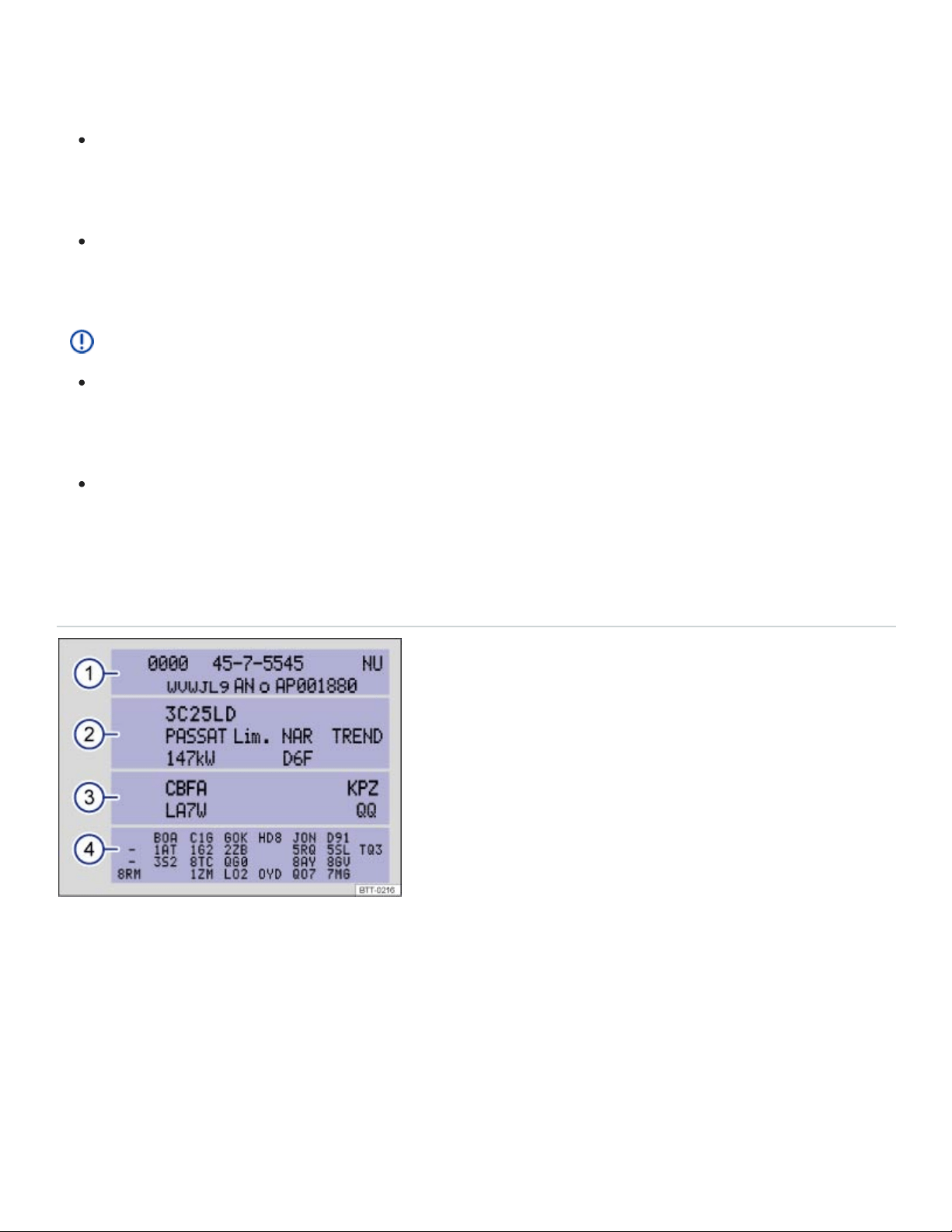
Exceeding maximum permissible weight ratings can result in vehicle damage, accidents, and se‐
rious personal injury.
Never let the actual weights at the front and rear axles exceed the permissible Gross Axle
Weight Rating. Also, never let the total of these actual weights exceed the Gross Vehicle
Weight Rating.
Always remember that the vehicle's handling and braking will be affected by extra load and the
distribution of this load. Adjust your speed accordingly.
NOTE
Always distribute the load evenly and as low as possible in the vehicle. The vehicle capacity
weight figures apply when the load is distributed evenly in the vehicle (passengers and
luggage).
When transporting a heavy load in the luggage compartment, carry the load as close to the
rear axle (as far forward) as possible so that the vehicle's handling and braking are affected as
little as possible.
Vehicle identification label
Fig.201Vehicle identification label: Shown in the example with engine identification code CBFA ③.
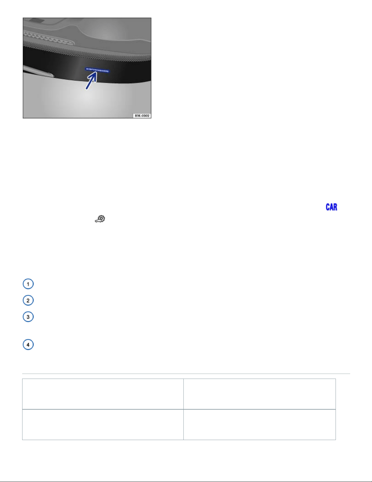
Fig.202Vehicle identification number (VIN).
Vehicle identification number (VIN)
The vehicle identification number is on a plate on top of the instrument panel on the driver side, and is
visible from the outside through the windshield ⇒Fig.202 (arrow). The view window is on the side at
the bottom of the windshield.
The vehicle identification number can be displayed in the Infotainment system by pressing the
button followed by the and Service function keys ⇒Vehicle settings menu .
Vehicle identification label
The vehicle identification label ⇒Fig.201 is affixed to the area of the spare wheel well underneath
the luggage compartment floor panel and contains the following information:
Vehicle identification number (VIN)
Vehicle type, engine output, and transmission
Engine and transmission identification codes, paint number, and interior type. In the example, the
engine identification code is CBFA ⇒Fig.201 .
Optional equipment and part numbers
Dimensions
Length 198.3 inch (5036 mm)
Width 77.9 inch (1978 mm)

Height (unloaded) 70 inch (1769 mm)
Wheelbase 117.3inch (2980mm)
Minimum turning circle diameter (wall to wall) 38.06 ft (12.35 m)
Track , front 67.2 inch (1708 mm)
Track , rear 67.8 inch (1723 mm)
Ground clearance (unloaded) 8.0 inch (203 mm)
Approach angle
– Off-road
20.4°
Departure angle 22.2°
Ramp angle 17.5°
NOTE
Please be careful when parking your vehicle in areas with parking barriers or curbs. These
vary in height and could damage your bumper and related parts if the front of your vehicle hits
a barrier or curb that is too high while you are getting into or out of a parking spot.
Always be careful when you enter a driveway or drive up or down steep ramps or over curbs
or other obstacles. Parts of the vehicle close to the ground may be damaged (such as bumper
covers, spoilers, and parts of the engine, suspension, and exhaust systems).
a)
a)
a)
a)

Slight differences to these figures are possible, depending on wheel and tire size fitted, tire inflation
pressure, equipment level, driving situation, and other factors.
Fuel capacities
Engine Fuel tank capacity
All engines About 18.6 Gallons (about 70.4 l).
Engine data
Introduction to the subject
In this chapter you will find information on the following subjects:
⇒2.0 l, 4 cylinder (175 kW)
⇒3.6 l, 6 cylinder (206 kW)
Fuel recommendations for gasoline engines
Using gasoline that does not meet minimum octane requirements can cause loss of engine perfor‐
mance, while the use of poor quality gasoline or octane levels below 87 can also cause engine dam‐
age. If Regular gasoline is recommended for your engine, you may be able to enhance engine perfor‐
mance by using Premium gasoline.
2.0 l, 4 cylinder (175 kW)
Read and follow the introductory information and safety information first⇒ Introduction to the
subject
Maximum power output
Injection technology TSI
Engine ID code DCGA
a)
a)

Maximum torque
258 lb-ft (350 Nm) at 1600 -
4500 rpm
No. of cylinders 4cylinders
Displacement 121 CID (1984 cc)
Data was not available at the time this Manual was printed.
Engine performance data using Premium grade gasoline ⇒Fuel and emission control system
3.6 l, 6 cylinder (206 kW)
Read and follow the introductory information and safety information first⇒ Introduction to the
subject
Maximum power output
Injection technology FSI
Engine ID code CDVC
Maximum torque
266 lb-ft (360 Nm) at 2750
rpm
No. of cylinders 6cylinders
Displacement 219 CID (3597 cc)
b)
a)
b)
a)