Loading ...
Loading ...
3
INSTALLATION INSTRUCTIONS - ELECTRIC RANGE
Four Conductor Wire Connection to Range
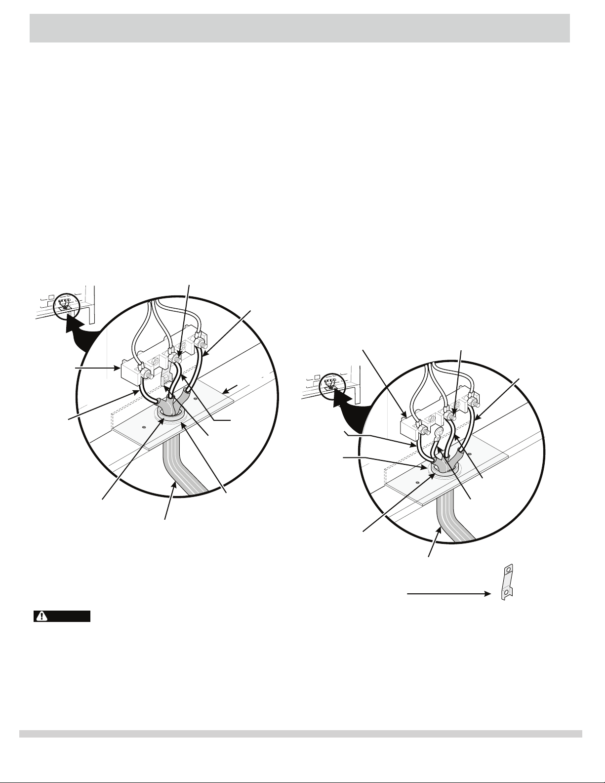
Where local codes does NOT permit connection of the
frame grounding conductor to the neutral wire of the
copper power supply cord (see Figure 9):
1. Remove the screws from the access plate at the lower
right end of the rear cover to expose range terminal
connection block.
3. Remove the grounding strap from the terminal block
and from the appliance frame.
4. Connect the ground wire (green) of the copper p
ower
supply cord to the frame of the appliance with the
ground screw, using the hole in the frame where the
ground strap was removed (see Figure 9).
5. Connect the neutral of the copper power supply cord
to the center silver-colored terminal of the terminal
block, and connect the other wires to the outer
terminals. Match wires and terminals by color (red wires
connected to the right terminal, black wires connected
to t
he left terminal).
6. Replace the terminal cover and replace the screws.
Terminal Block Silver Colored Terminal
Red
Wire
Neutral
(White Wire)
Ground (Bare
Copper Wire)
To 240 V Receptacle
A User Supplied
Strain-relief Must
Be Installed at
This Location
Black Wire
1 1/8" (2,9 cm)
Dia. Direct
Connection Hole.
Punch Out
Knockout for 1
3/8" (3,5 cm)
Dia. Cord Kit
Hole.
NOTE: Be sure to remove the
supplied grounding strap.
Figure 9
Three Conductor Wire Connection to Range
If local codes permit connection of the frame grounding
conductor to the neutral wire of the copper power supply
cord (see Figure 8):
1. Remove the screws from the access plate at the lower
right end of the rear cover to expose range terminal
connection block.
3. Using the nuts supplied by the manufacturer,
connect the neutral of the copper power supply cord
to the center silver-co
lored terminal of the terminal
block, and connect the other wires to the outer
terminals. Match wires and terminals by color (red
wires connected to the right terminal, black wires
connected to the left terminal) (see figure 8).
4. Replace the terminal cover and replace the screws.
2. Follow manufacturer guidelines for firmly securing
the strain relief and power cord.
2. Follow manufacturer guidelines for firmly securing
the strain relief and power cord.
Silver Colored Terminal
1 1/8" (2,9 cm) Dia.
Direct Connection
Hole. Punch Out
Knockout for 1
3/8" (3,5 cm) Dia.
Cord Kit Hole.
To 240 V
Receptacle
The Supplied
Strain-relief Must
Be Installed at This
Location.
Black
Wire
Terminal
Block
Cord
Mounting
Plate
Neutral
(White Wire)
Grounding
Strap
Red Wire
Figure 8
Checking Operation
Refer to the Use and Care Guide for operation.
CAUTION Do not touch cooktop glass or elements.
They may be hot enough to burn you.
Before You Call for Service
Read the Before You Call for Service Checklist and
operating instructions in your Use and Care Guide. It
may save you time and expense. The list includes
common occurrences that are not the result of
defective workmanship or materials in this appliance.