
ITEM #: RV-W841
IMPORTANT SAFETY INSTRUCTIONS
• To avoid injury or damage, mount only on a surface that is sturdy.
• To avoid electric shock, make sure the electricity is turned off at the main
circuit breaker panel. If you are replacing an existing fixture, turn off the
following in order: fixture, wall switch, and main fuse or breaker box.
Note: Some types of fuses must be unscrewed to shut the power off.
• If you are unclear as to how to proceed, please consult a licensed
electrician.
UNPACK THE FIXTURE: Check the contents of the box. Box should contain all items on the parts diagram.
For any replacement parts or installation issues, please Contact Us!
Email: [email protected]
Facebook/Instagram: @KiraHomeDecor
Phone: 888.208.2085
INSTALLATION INSTRUCTIONS - FLAT WALL SURFACE
*See next page for junction box installation
1. Unscrew Backplate Screws (E) to remove Mounting Plate (A) from Backplate (D).
2. Position Mounting Plate (A) on desired location on the wall ensuring the Backplate Screw (E) holes on
Mounting Plate (A) are positioned on the left and right.
3. Fasten Mounting Plate (A) to wall:
a. If fastening to a wall stud: Secure using (4) wood screws and screwdriver.
b. If fastening to a hollow area: Mark location to install plastic anchors. Drill 1/4” pilot holes on the
marked spots and insert plastic anchors. Affix to anchors.
4. Place Backplate (D) against the wall, ensuring holes on each side of Backplate (D) align with the holes on
Mounting Plate (A). Secure Backplate (D) to Mounting Plate (A) with Backplate Screws (E).
5. Secure Shade (G) to Socket (F) with Socket Ring (H).
Note: Socket Ring (H) is attached to Socket (F). Remove it prior to installing Shade (G).
6. Position Mounting Channel (I) on the wall between Backplate (D) and the floor.
Note: Both Cord Covers (J) snap onto (1) Mounting Channel (I).
7. Fasten Mounting Channel (I):
a. If fastening to a wall stud: Secure using (4) wood screws and screwdriver.
b. If fastening to a hollow area: Mark location to install plastic anchors. Drill 1/4” pilot holes on the
marked spots and insert plastic anchors. Affix to anchors.
8. Place Power Cord (K) into Mounting Channel (I) and affix first Cord Cover (J) over the upper half of
Mounting Channel (I). Affix second Cord Cover (J) to the bottom half of Mounting Channel (I).
Note: If Cord Covers (J) do not snap into place, widen Mounting Channel (I) by gently pulling it apart.
9. Plug Power Cord (K) into outlet.
10. Install light bulb (not included) into Socket (F).
INSTALLATION INSTRUCTIONS - JUNCTION BOX
1. Unscrew Backplate Screws (E) to remove Mounting Plate (A) from Backplate (D).
2. Remove Power Cord (K):
a. Turn Wire Connectors (C) in a counter-clockwise direction to detach Power Cord (K) from fixture
wires.
b. Undo the safety knot on Power Cord (K) and remove from the bottom of Backplate (D).
3. Secure Mounting Plate (A) to the junction box (not included) using Mounting Screws (B) provided, ensuring
the Backplate Screw (E) holes on Mounting Plate (A) are positioned on the left and right.
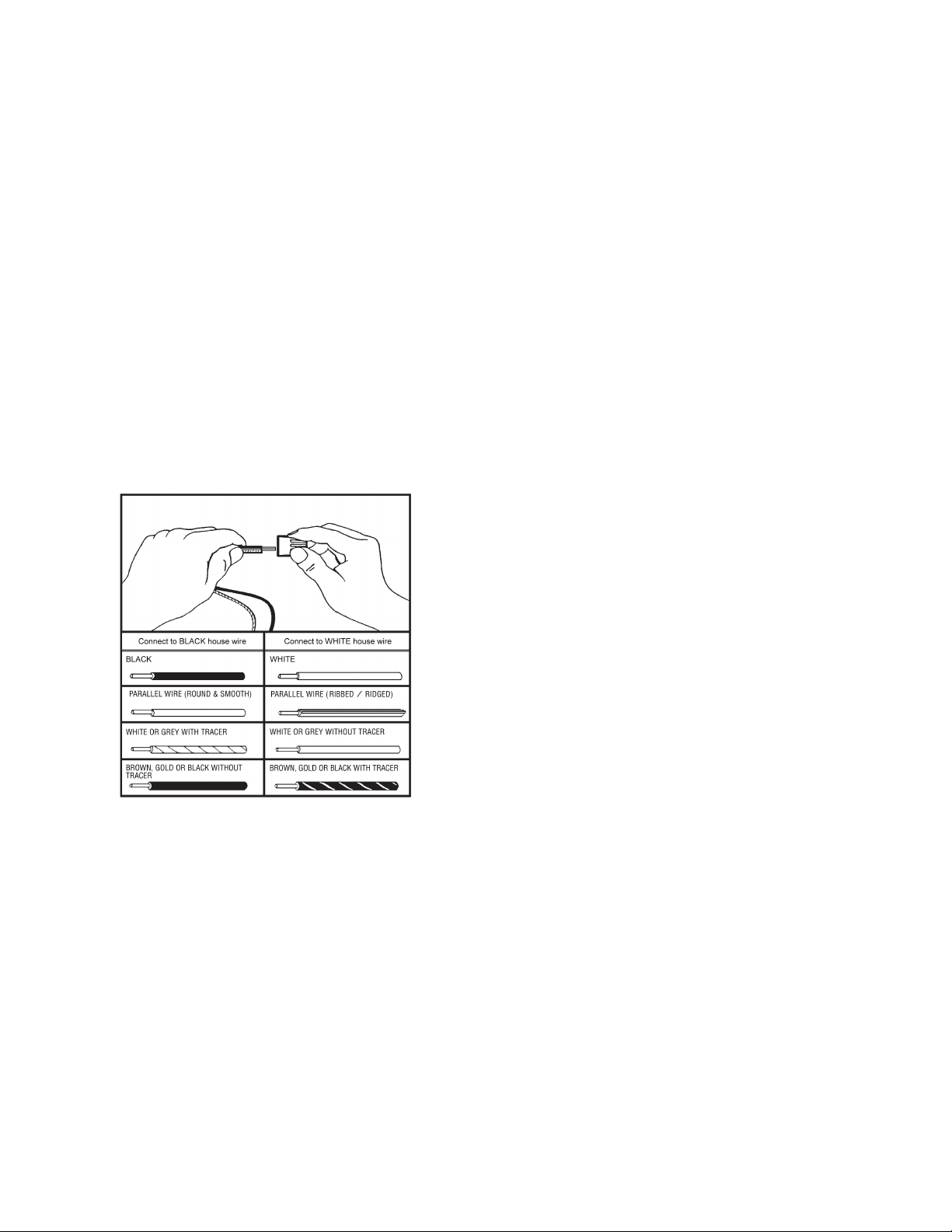
4. Using the wire graph below, connect the appropriate wires from the fixture to the corresponding wires in
the electrical junction box (not included) and secure Wire Connectors (C).
A. Connect the ground wire (bare copper or green) from
your fixture to the:
1) ground wire in the junction box, or
2) ground screw in the junction box
B. Connect the BLACK house wire to fixture hot wire
that corresponds to diagram (black, round &
smooth, white/grey with tracer, brown/gold without
tracer).
C. Connect the WHITE house wire to fixture neutral wire
that corresponds to diagram (white, ribbed/ridged,
white/grey without tracer, brown/gold with tracer).
5. Place all wires and Wire Connectors (C) back into the junction box.
6. Place Backplate (D) against the wall, ensuring holes on each side of Backplate (D) align with the holes on
Mounting Plate (A). Secure Backplate (D) to Mounting Plate (A) with Backplate Screws (E).
7. Secure Shade (G) to Socket (F) with Socket Ring (H).
Note: Socket Ring (H) is attached to Socket (F). Remove it prior to installing Shade (G).
8. Install light bulb (not included) into Socket (H).
Enjoy your new fixture!
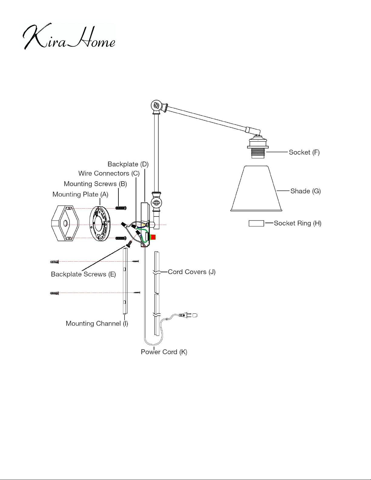
ITEM #: RV-W841 - PARTS DIAGRAM
HELPFUL TOOLS: Safety Goggles, Screwdriver, Ladder