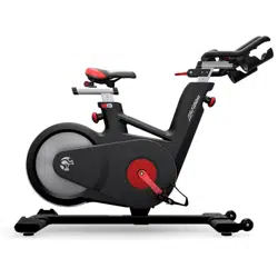
With the LIFE FITNESS Indoor Cycle, you have chosen a high-quality product, which is designed according to the latest technical developments and thus fulfils the highest standards in quality and reliability.
This high level of reliability can however only be ensured with regular care and maintenance. Adhering to the maintenance procedures outlined in this manual will ensure a maximized stability and prolonged lifespan with a minimal maintenance effort. This will guarantee long standing, interruption-free operation.
Instructions on operation and managing training for the WattRate® TFT Computer can be found in the computer user manual also included with delivery.
HOW TO ASSEMBLE THE INDOOR CYCLE
WARNING! Avoid high fluctuations in temperature whilst transporting the bike from the store to the installation site. If there are nevertheless large fluctuations in temperature, please allow the bike to adjust to the surrounding temperature before proceeding with assembly
DO NOT REMOVE THE SAFETY PIN BEFORE THE HANDLEBAR HAS BEEN MOUNTED ON THE UPPER HORIZONTAL HANDLE BAR SLIDER!
THE VERTICAL HANDLEBAR STEM OF THE INDOOR CYCLE IS SPRING LOADED AND WILL EXTEND QUICKLY UNLESS THE HANDLEBAR IS MOUNTED ONTO THE STEM. EXTENSION OF THE STEM WITHOUT THE MOUNTED HANDLEBAR MAY CAUSE INJURY OR/AND DAMAGE TO THE INDOOR CYCLE.
MOUNT THE HANDLEBAR TO THE STEM WITH 2 COUNTER SUNK HEX BOLTS. TIGHTEN TO 30 NM WITH A TORQUE WRENCH. THE BOLTS ARE PRE-COATED WITH A THREAD LOCK WHEN TIGHTENED FOR THE FIRST TIME. IF THE BOLTS SHOULD LOOSEN, GLUE BOLTS WITH LOCKTITE (R) 2701 UPON RETIGHTENING.
LOOSEN THE THUMB LEVER AND PUSH THE HORIZONTAL SLIDER TO THE FORWARD POSITION.
LOCK THE THUMB LEVER. REMOVE THE LIMIT STOP WITH A 3 MM HEX KEY.
NEVER PULL THE HANDLEBAR TOWARD THE SEAT WHEN THE LIMIT STOP IS REMOVED. THIS WILL DAMAGE THE INTERNAL CABLE!
INSERT AND FASTEN THE END CAP WITH A CAP HEAD SCREW AND 3 MM HEX KEY.
LOOSEN THE SAFETY PIN AND REMOVE IT USING A 6 MM HEX KEY.
LIFT THE HANDLEBAR TO POSITION 6 AND SCREW THE POP PIN KNOB COMPLETELY INTO THE FRAME TO LOCK THE HANDLEBAR STEM.
MOUNT THE RESISTANCE/BRAKE LEVER CAREFULLY ON TO THE VERTICAL HANDLEBAR STEM USING A 2.5 MM HEX KEY.
SLIDE THE CABLE THROUGH THE OPENING IN THE LOWER CONSOLE BRACKET.
FASTEN THE BRACKET WITH TWO BOLTS WITH 3 MM HEX KEY.
REMOVE THE BACKING FROM THE ADHESIVE ON BOTH SIDES OF THE BRACKET
POSITION THE CABLE AND CONNECTOR INTO THE CONTOUR OF THE BRACKET SO THE CONNECTOR IS FLUSH WITH THE BRACKET.
POSITION THE BRACKET COVER ON THE BRACKET AND FASTEN WITH COUNTERSUNK BOLT WITH A 2.5 MM HEY KEY.
SLIDE THE SPACER BETWEEN THE BRACKET AND HANDLEBAR.
SLIDE THE BIKE COMPUTER ONTO THE COMPUTER BRACKET.
FASTEN THE BIKE COMPUTER INTO PLACE FROM THE UNDERSIDE OF THE HANDLEBARS WITH ONE BOLT.
The computer user manual is enclosed separately and contains information for setup and operation.
WARNING! Attach the pedal marked R on the right crank and tighten by turning clockwise (standard right-hand thread). Attach the pedal marked L on the left crank and tighten by turning counter-clockwise (left-hand thread). Please make sure that both pedals are fastened with sufficient force (55 NM), to ensure that the bolt does not become loose during use.
The threads are provided with TufLok® at the factory to prevent them from becoming loose during use. If bolts are loosened after initial assembly, we recommend using medium-strength LOCTITE® 243 when reassembling
Test the function of the adjustable handlebar and seat.
Move the resistance/brake lever up and down multiple times.
Move the handlebars and seat up and down and the back and forth. Test the function of the thumb levers on the sliders and the function of the pop pin knobs.
TEST FUNCTION OF HANDLEBAR AND SEAT HEIGHT ADJUSTMENT, HORIZONTAL SLIDERS AND EMERGENCY BRAKE.
INSTALLATION AND SETUP
Instructions stated in this manual must be performed during initial installation of the LIFE FITNESS Indoor Cycle in order to ensure optimal performance and a long lifespan. Please read and follow the following instructions carefully. If the Indoor Cycles are not installed and configured as described, the components may be subjected to excessive wear and tear and the bike may become damaged. If you have any questions regarding installation, please contact [email protected].
Please note: Lubricants are required for some maintenance procedures. Please only use an acid- and solvent-free spray lubricant and white lithium grease.
Make sure the bike is level. If bike rocks on the floor, turn the levelling feet underneath the front and/or rear stabilizer until the rocking motion is eliminated. Make sure that the levelling feet are not screwed out further than 10 mm.
Verify emergency brake function to make sure that it is working properly.
Check that both crank arm Allen bolts, with which the cranks (on the right and left side of the bottom bracket) are fastened, are secure (tightening torque 60 NM). These bolts are provided with TufLok® at the factory to prevent them from becoming loose during use. If the bolts become loose, we recommend applying medium-strength LOCTITE® 243 and then reattaching the crank fixing bolts with a tightening torque of 60 NM.
Wipe down bike frame with a rag moistened with acid and solvent-free spray lubricant.
Some parts of the bike may become loose during shipment. Check crank arms and all exposed screws, bolts and nuts, and make sure that they are all secure and properly tightened.
CUSTOMER SERVICE
Provide the customer with basic maintenance instructions, and direct them to detailed maintenance instructions.
Have the sign-off sheet for the manual, explanation of maintenance procedures and verification of impeccable condition of the bikes confirmed by the customer when handing over the goods. A copy of the confirmation should be counter signed by yourself and a copy of the confirmation should also be left with the customer.
Repairs must only be carried out by manufacturer authorised service technicians
HOW TO ADJUST THE INDOOR CYCLE
The Life Fitness Indoor Cycle can be very easily adjusted, depending on the requirements of various user groups. This enables maximum riding comfort to be ensured whilst achieving optimal training results. The configurations described in the following paragraphs demonstrate just a few of the most often used adjustment variations of which the Indoor Cycle is capable. It is up to the user to adjust the Indoor Cycle to a riding position best suited to their requirements.
ADJUSTING THE SEAT HEIGHT:
Sit on the saddle and ensure that your hip is not tilted to one side when the pedal has assumed the position as shown in the picture. Place your shoes in the toe clips (cages) on the pedals, or in the SPD cleats if you are using cycling shoes.
WARNING! Do not adjust seat and handlebar during exercise. Ensure that the pop-pin-knobs used for the height adjustment of the handlebar and seat are properly tightened and the thumb levers for horizontal adjustment are closed, before you sit on the bike. Always step off the bike when making adjustments to the handlebars and/or saddle.
Start pedaling slowly, until the pedal has reached the position as shown in the picture. The saddle height should be adjusted so that your knees are always slightly bent when the pedal is at its lowest position without dropping your hip to one side. Rule of thumb: When standing next to the bike, the upper edge of the saddle should be a hand‘s width/four fingers below your iliac crest. Please avoid cycling with your knees fully extended or your hip tilted to one side.
ADJUSTING THE SADDLE HORIZONTALLY:
Properly positioning the saddle horizontally is very important in order to avoid injury to the knees. Sit on the saddle and move the pedals until the crank arms are in the horizontal position.
The knee of your forward-facing leg should be positioned directly above the center of the pedal. If this does not correspond to your bike‘s setting, please align the horizontal saddle adjustment to the front or rear in order to attain this seat position.
HANDLEBAR POSITIONING:
Begin with the top of the handlebars at approximately the same height as the saddle (dotted horizontal line A in the drawing below) for inexperienced users set to the “0“ marking (see dotted vertical line B in the drawing below). If your knees touch the handlebars or if you experience back discomfort when pedalling in the standing riding position for extended periods, the handlebars should first be adjusted slightly higher.
The next step is to adjust the horizontal position of the handlebars as precisely as possible to your height. An ideal and comfortable seating position for inexperienced riders is achieved if your back assumes an inclination angle of 45° in reference to the horizontal line (A).
The handlebars offer a wide variety of hand positions and adjustment possibilities, which provide the experienced rider with every possibility to find his/her ideal seating and hand positioning.
It is recommended to change hand positions frequently during extended workouts in order to minimise one-sided and monotonous exertions on your muscles, ligaments and joints.
RESISTANCE ADJUSTMENT:
The resistance adjustment can be set precisely and regulated in fine increments according to the requirements of the cyclist by moving the resistance/emergency lever up or down. The adjustment lever has 110° range of motion . When the lever is up, the resistance is 0% and when it is in the down position, 100%. When moved beyond 100%, the brake will engage. The training resistance is displayed accurately on the Indoor cycle computer. This Indoor Cycle is fitted with a magnetic brake system and therefore, the resistance increases with the pedaling frequency.
Never pedal backwards under resistance, as this can loosen the screws connecting the pedals to the crank arm and the two may even become detached. To stop the flywheel during use, the resistance/emergency brake lever must be pressed down. During training, please make sure your shoes are placed in the toe clips (cages) provided or if you are using cycling shoes, that they are connected with the SPD cleats.
HOW TO OPERATE THE INDOOR CYCLE
For safety reasons, please always make sure you pedal in a controlled manner and adjust your pedalling frequency to your own cycling capabilities.
MOVING THE INDOOR CYCLE:
It is recommended that two people move the Indoor Cycle. In order to prevent accidents and damage to the plug-in sockets of the handlebars it is necessary to firmly fix the vertical handlebar adjustment before the wheel is tilted. Please take extra care when moving the Indoor Cycle over uneven surfaces. A second person is advisable here, to prevent the cycle from tilting to one side. Allow a minimum safety distance away from the nearest equipment, objects or walls as illustrated below.
Check the stability of the Indoor Cycle where it is to be operated and if necessary adjust the levelling feet underneath the front or rear stabilizers to ensure the desired stability.
IMPORTANT! Please do not unscrew the levelling feet more than 10 mm! The free standing Indoor cycle shall only be installed and operated on a stable and leveled floor.
PREVENTATIVE MAINTENANCE
WARNING!
Please carefully observe the following instructions. The maintenance and care procedures must be performed in the regularity set out, to ensure maximum operating safety and lifespan. Irregularly observed maintenance and care procedures will lead to increased wear to the product and will void the warranty. If you have any further questions on this topic, please contact our technical support.
Please only use the acid- and solvent-free maintenance and care agent recommended by us to prevent damage to components of the Indoor Cycle.
DAILY MAINTENANCE:
Make sure that the Indoor Cycle is leveled and does not rock (if necessary adjust as described on p.21).
Cleaning: The Indoor Cycle must be regularly cleaned after each use for reasons of hygiene. Ensure that there are sufficient soft cloths or paper towels and maintenance and disinfection agent available. First disinfect the saddle and handlebars with a suitable agent and then wipe all bodily residues off the entire Indoor Cycle.
WEEKLY MAINTENANCE:
Cleaning: Depending on how often the Indoor Cycle is used, it must be extensively cleaned once a week. To do this, spray a maintenance spray onto a soft cloth and clean all plastic parts, the entire flywheel, exposed framework parts including stabilizers and the plastic casing.
Never spray maintenance spray or anything else directly onto the flywheel or pedal to ease cleaning, as this could cause the drive belt to slip during use, reduce braking performance or damage internal components
BI-WEEKLY MAINTENANCE:
1. Emergency brake: To ensure operating safety, the emergency brake must be regularly checked to make sure it is functioning properly. To do this, completely press down the resistance/brake lever whilst pedalling. When functioning optimally, it should produce an immediate braking effect and bring the flywheel to a complete standstill.
The flywheel is only released again by the emergency braking function after coming to a complete standstill and when the pressure is removed from the pedals.
2. Saddle adjustments: To maintain the easy adjustment, the vertical and horizontal saddle posts must be regularly cleaned and lubricated. To do this, position the vertical saddle post (A) in the uppermost position, spray with maintenance spray and rub down the entire exterior surfaces including the horizontal post with a soft cloth.
Clean sweat residues off the contact surfaces (B) of the horizontal saddle post beforehand and if necessary apply a small amount of lithium/grease.
3. Handlebars: To maintain the easy adjustment of the handlebar posts, the vertical and horizontal handlebar posts must be regularly cleaned and lubricated. To do this, position the handlebars (A) in the uppermost position, spray the handlebar posts with maintenance spray and rub down the entire exterior surfaces including the horizontal post with a soft cloth. Clean sweat residues off the contact surfaces of the horizontal handlebar post (B) beforehand and if necessary apply a small amount of lithium.
MONTHLY MAINTENANCE:
1. Connecting elements: During the course of regular maintenance and care procedures, all bolts, nuts etc. on the Indoor Cycle must be checked to ensure that they are properly tightened and function correctly. Parts showing wear or damage (saddle, pedal teeth, pedals, SPD system) must be replaced.
2. Vertical adjusting of the handlebar and saddle: To ensure the easy adjustment of the vertical handlebar and saddle posts, the thread on the pop-pin-knob must be lubricated. We recommend lithium grease
Life Fitness does not offer the option but you can always find a saddle cover that will work.
#4 Can I easily pair with my Polar HRM WITH BLUETOOTH? I can pair at the gym with your older GX version...
Yes, a chest strap monitor with BT or Ant+ signal transmission will pair with the IC6/IC7/IC8 consoles. It will not pair HR with a wearable device (like watch or arm band).
#5 Does this model have the newer wattrate tft computer 2.0?
Yes, it has the new redesigned and re-engineered WattRate® TFT Computer 2.0.