
VERSION B1
Dual Input DC-DC On-Board Battery Charger with MPPT
Renogy
12V 30A/50A
USER MANUAL
Applicability
The user manual applies to the following products:
z
Renogy 12V 30A Dual Input DC-DC On-Board Battery Charger with MPPT (RBC30D1S)
z
Renogy 12V 50A Dual Input DC-DC On-Board Battery Charger with MPPT (RBC50D1S)
Disclaimer
z
Renogy ensures the accuracy, sufficiency, and the applicability of information in the user
manual at the time of printing due to continual product improvements that may occur.
z
Renogy assumes no responsibility or liability for personal and property losses, whether
directly and indirectly, caused by the
user’s
failure to install and use the product in
compliance with the user manual.
z
Renogy is not responsible or liable for failures, damages, or injuries resulting from repair
attempted by unqualified personnel, improper installation and operation.
z
The illustrations in the user manual are for demonstration purposes only. Details may
appear slightly different depending on product revision and market region.
z
Renogy reserves the right to change the information in the user manual without notice.
For the latest user manual, visit renogy.com.
Copyright
Renogy 12V 30A/50A Dual Input DC-DC On-Board Battery Charger with MPPT User Manual
© 2022 Renogy. All rights reserved.
All information in the user manual is subject to copyright and other intellectual property rights
of Renogy and its licensors. The user manual may not be modified, reproduced, or copied, in
whole or in part, without the prior written permissions of Renogy and its licensors.
Trademark
The following are registered trademarks of Renogy:
RENOGY
The registered trademarks in the user manual are the property of Renogy. The unauthorized
use of the trademarks is strictly prohibited.
Date and Revision
February 2023, Revision B1

Table of Contents
Important Safety Information .................................................................................................. 01
Symbols Used .................................................................................................................. 01
General Safety Information .............................................................................................. 01
Overview................................................................................................................................. 03
Introduction ...................................................................................................................... 03
Key Features .................................................................................................................... 03
Charging and Activation Logics .............................................................................................. 04
MPPT Technology ............................................................................................................ 04
Four Charging Stages ...................................................................................................... 05
Lithium Battery Activation ................................................................................................. 06
Package Contents .................................................................................................................. 07
Optional Accessories .............................................................................................................. 09
Product Overview ................................................................................................................... 10
Wiring Diagram ....................................................................................................................... 11
Recommended Cable and Fuse Sizing .................................................................................. 12
Recommended Cable Sizing ............................................................................................ 12
Recommended Fuse Sizing ............................................................................................. 13
Components & Tools .............................................................................................................. 14
Preparation ............................................................................................................................. 15
Checking Battery Charger ................................................................................................ 15
Checking Auxiliary Battery ............................................................................................... 16
Checking Solar Panel (Optional) ...................................................................................... 17
Checking Automobile Alternator (Optional) ...................................................................... 19
Battery Charger Wiring ........................................................................................................... 20
Mounting ................................................................................................................................. 22
Temperature Sensor ............................................................................................................... 23
Voltage Sensor ...................................................................................................................... 24

Communication....................................................................................................................... 25
Operation ................................................................................................................................ 26
Selecting the Battery Type ............................................................................................... 26
Battery Charging Parameters ........................................................................................... 29
User Mode ........................................................................................................................ 30
Working Logic ......................................................................................................................... 33
To Solar Panel .................................................................................................................. 33
To Starter Battery ............................................................................................................. 34
To Both Solar Panel and Starter Battery .......................................................................... 35
LED Indicators ........................................................................................................................ 41
Alternator / Charging Indicator ......................................................................................... 41
Battery Type Indicator ...................................................................................................... 42
Troubleshooting ...................................................................................................................... 43
Alternator / Charging Indicator ......................................................................................... 43
Solar Charging Indicator .................................................................................................. 43
Auxiliary Battery Indicator ................................................................................................ 43
Technical Specifications ......................................................................................................... 44
Dimensions ............................................................................................................................. 45
Maintenance ........................................................................................................................... 46
Inspection ......................................................................................................................... 46
Cleaning ........................................................................................................................... 46
Storage ............................................................................................................................. 46
Emergency Responses .......................................................................................................... 47
Fire ................................................................................................................................... 47
Flooding ........................................................................................................................... 47
Smell ................................................................................................................................ 47
Noise ................................................................................................................................ 47
Technical Support ................................................................................................................... 48

Important Safety Information
01
Important Safety Information
The user manual provides important installation, operation, and maintenance instructions for
Renogy 12V 30A/50A Dual Input DC-DC On-Board Battery Charger with MPPT (hereinafter
referred to as battery charger) . Read the user manual carefully before installation and operation
and save it for future reference. Failure to observe the instructions or precautions in the user
manual can result in electrical shock, serious injury, or death, or can damage the battery charger,
potentially rendering it inoperable. The installation and service of the battery charger might require
knowledge of electricity and is recommended to be carried out by qualified personnel.
Symbols Used
The following symbols are used throughout the user manual to highlight important information:
WARNIN
G
Indicates a potentially dangerous condition which could result
in injury or death.
CAUTIO
N
Indicates a critical procedure for safe and proper installation
and operation.
NOT
E
Indicates an important step or tip for optimal performance.
INF
O
Indicates that more information is available in other documents
relating to the subject.
General Safety Information
WARNING
z
Do not puncture, drop, crush, penetrate, shake, strike, or step on the battery charger.
z
Do not open, disassemble, repair, tamper with, or modify the components of the battery
charger.
z
Install the battery charger on a vertical surface indoors protected from direct sunlight, high
temperature, and water. Make sure there is good ventilation.
z
Do not insert foreign objects into battery charger.
z
Risk of explosion! Never install the battery charger in a sealed enclosure with flooded
batteries! Do not install in a confined area where battery gases can accumulate.
z
Confirm the polarities of the devices before connection. A reverse polarity contact will result in
abnormalities.
z
Refer to the Recommended Cable and Fuse Sizing in this user manual, and select the
appropriate cables and fuses according to the usage.
z
Keep the battery charger out of the reach of children.
z
Wear proper protective equipment and use insulated tools during installation and operation.
z
Do not touch the connector contacts while the battery charger is in operation.
z
Disconnect all connectors from the battery charger before maintenance or cleaning.
z
Do not dispose of the battery charger as household waste. Comply with local, state, and
federal laws and regulations and use recycling channels as required.
Symbols Used General Safety Information

Important Safety Information
02
z
In the event of fire, use fire extinguishers suitable for electrical equipment.
z
If the battery charger is installed improperly on a boat, it may cause damage to the corrosive
agents of the boat. Please have the battery charger by a qualified electrician.
CAUTIO
N
z
Do not expose battery charger to flammable or harsh chemicals or vapors.
z
Ensure that there is no water source including downspouts, sprinkles, or faucets above or
near the battery charger.
z
Ensure that the battery pack is properly connected before installation.
Symbols Used General Safety Information

Important Safety Information Overview
03
Introduction
Renogy 12V 30A/50A Dual Input DC-DC On-Board Battery Charger with MPPT provides you with
many options. With multple stage and input, the battery charger can charge the auxiliary battery
with a starter battery connected to an alternator or with solar panels connected directly to the
battery charger.
While the alternator of your car prioritizes the starter battery, the battery charger allows your solar
system to charge the auxiliary battery first. It is a smart way to keep the battery fully charged and
off-grid for longer. The battery charger can charge the flooded, gel, AGM, or lithium battery. With
the BT-2 Bluetooth Module and the DC Home app, you can monitor the device remotely through
your phone in real time.
Key Features
z
Robust and Sleek Design
The housing of the battery charger is made of steel plates to ensure its firmness and a more
fashionable appearance.
z
Multi-input for Battery Charging
The battery charger offers you many options to charge the auxiliary battery. With multple input,
it can charge the auxiliary battery with a starter battery connected to an alternator or with solar
panels connected directly to the battery charger.
z
Multi-stage Battery Charging
Up to three stage battery charging including bulk, boost, and float as well as equalization for select
battery types
z
Multiple Protections
The battery charger is equiped with undervoltage protection, overvoltage protection, overload
protection, overtemperature protection, reverse current protection, reverse polarity protection, and
short circuit protection.
z
RJ45 Communication Port Featured
With the BT-2 Bluetooth Module and the DC Home app, you can monitor the update parameters
of the battery charger remotely through your phone.
Overview
Introduction
Key Features
Charging and Activation Logics
04
MPPT Technology
Based on MPPT (Maximum Power Point Tracking) technology, the battery charger can extract
maximum power from the solar panel. With an automatic tracking algorithm, the MPPT technology
can track the voltage of the maximum power point that changes with weather conditions, ensuring
the harvest of the maximum power throughout the day.
▇
Current Boost
Generally, the battery charger will “boost” the current in the solar system. The power generated
in the solar panel is the same as the power delivered to the battery pack. Power is the product of
voltage (V) x amperage (A).
Therefore, assuming 100% efficiency:
Power In = Power Out
Volts In * Amps In = Volts out * Amps out
The efficiency of the battery charger is about 92% to 95%. As the maximum power point voltage
of the solar system is greater than the battery pack voltage, the potential difference is proportional
to the current boost. The voltage of the solar panel needs to be stepped down to a rate at which
the battery can be charged in a stable manner. Compared with traditional battery chargers, the
battery charger does not waste the stepped down voltage. It is entirely possible to have the solar
module input 8 amps of current into the battery charger, and have the battery charger output 10
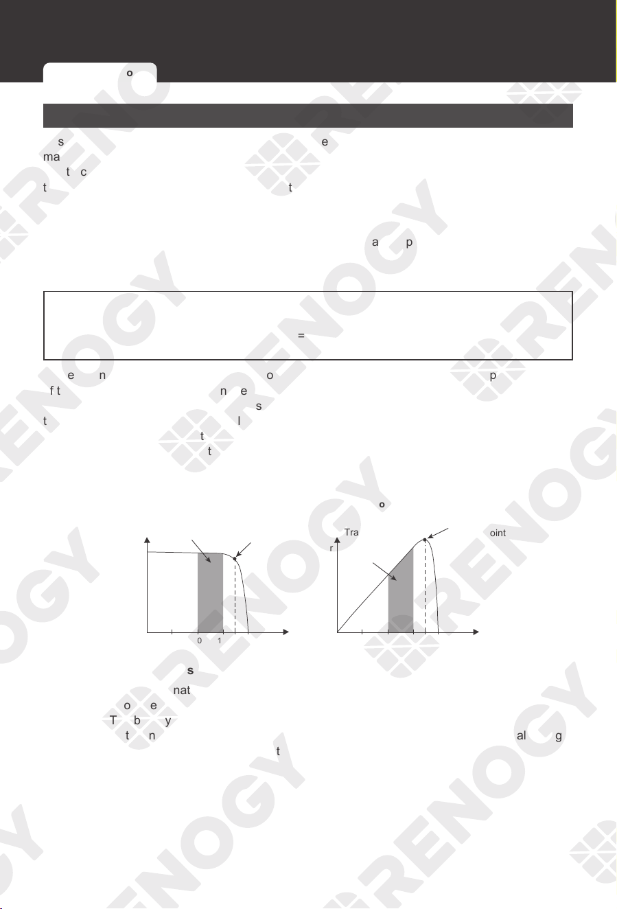
amps of current to the battery pack. The following shows a graphic point about the output of MPPT
technology.
10 15 17 10 15 17
Current vs.Voltage (12V System) Output Power (12V System)
Typical Battery
Voltage Range
Traditional
Controller
Operating
Range
Maximum
Power Point
Maximum
Power Point
Current
Power
Voltage Voltage
▇
Limiting Effectiveness
High temperature is the natural enemy of solar panels. With the increase of ambient temperature,
the operating voltage (Vmp) of the solar panel decreases, which limits the power generation of the
solar panel. The battery charger encounters an inevitably decrease in charging performance even
with the MPPT technology. In this case, it is better to use solar panels with higher nominal voltage,
so that the battery can still get current boost even if the voltage drops proportionally.
Charging and Activation Logics
MPPT Technology Four Charging Stages Lithium Battery Activation
Charging and Activation Logics Charging and Activation Logics
05
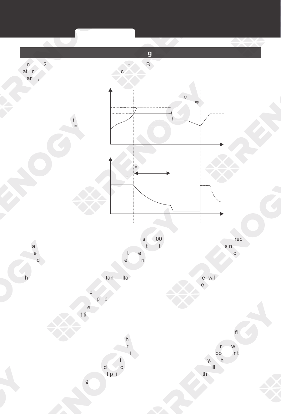
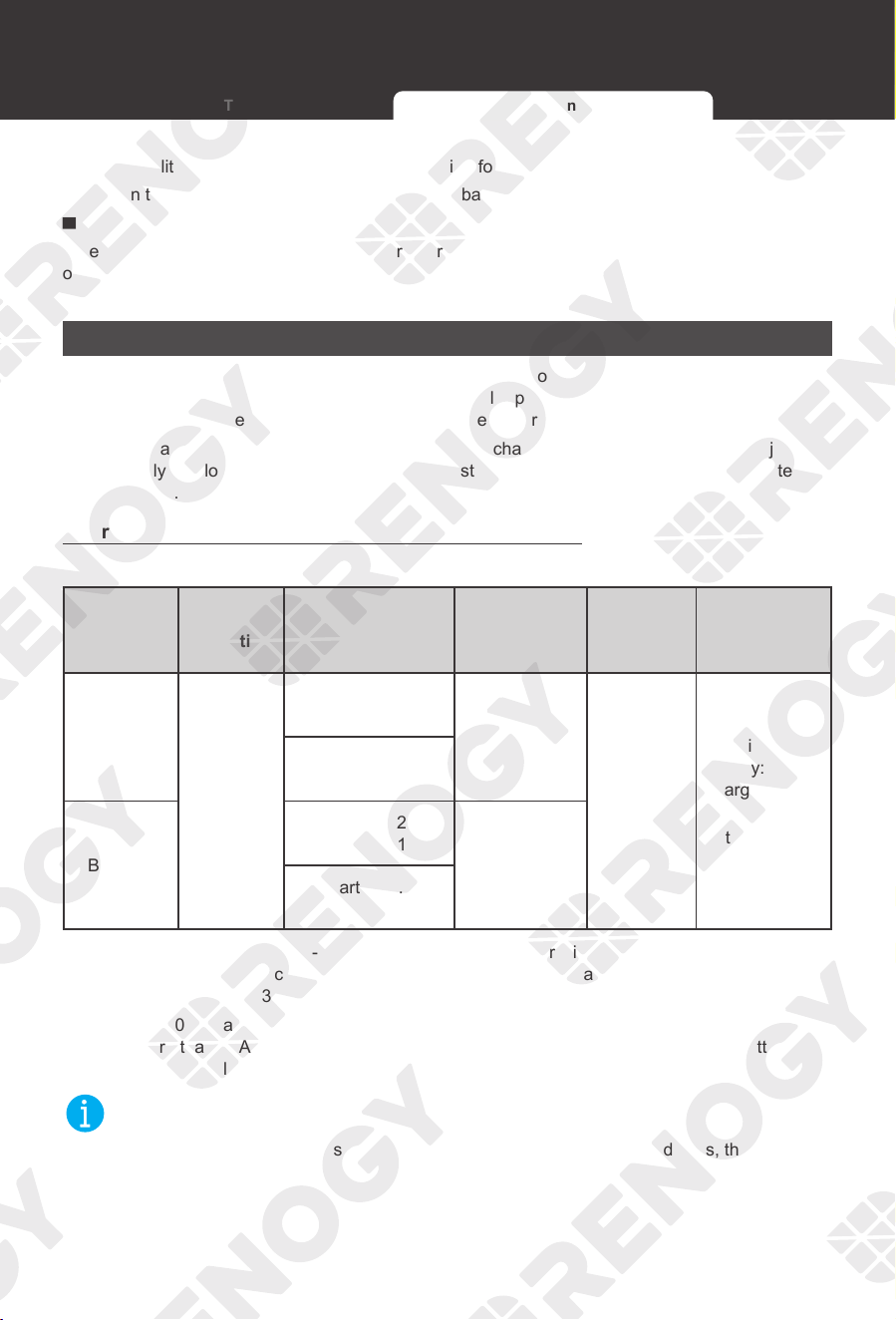
Four Charging Stages
Renogy 12V 30A/50A Dual Input DC-DC On-Board Battery Charger with MPPT has a four-stage
battery charging algorithm for a rapid, efficient, and safe battery charging. They include: Bulk
Charge, Boost Charge, Float Charge, and Equalization.
A
Time
Time
Charging
Current
Fast charging
B
Constant voltage charging
C
Floating charging
Equalize charging voltage
Boost charging voltage
Float charging voltage
Charging return voltage
Maximum
current
Constant pressure time
Cumulative Time
(Range:10-600 min)
: 2hr
: 2hr
Battery
Voltage
▇
Bulk Charge:
This algorithm is used for day to day charging. It uses 100% of available solar power to recharge
the battery and is equivalent to constant current. In this stage the battery voltage has not yet
reached constant voltage (Equalize or Boost), the battery charger operates in constant current
mode, delivering its maximum current to the batteries (MPPT Charging) .
▇
Constant Charging:
When the battery reaches the constant voltage set point, the battery charger will start to operate
in constant charging mode, where it is no longer MPPT charging. The current will drop gradually.
This has two stages, equalize and boost and they are not carried out constantly in a full charge
process to avoid too much gas precipitation or overheating of the battery.
Boost Charge: Boost stage maintains a charge for 2 hours by default. The user can adjust the
constant time and preset value of boost per their demand.
▇
Float Charge:
After the constant voltage stage, the battery charger will reduce the battery voltage to a float
voltage set point. Once the battery is fully charged, there will be no more chemical reactions and
all the charge current would turn into heat or gas. Because of this, the battery charger will reduce
the voltage charge to smaller quantity, while lightly charging the battery. The purpose for this is to
offset the power consumption while maintaining a full battery storage capacity. In the event that a
load drawn from the battery exceeds the charge current, the battery charger will no longer be able
to maintain the battery to a Float set point and the battery charger will end the float charge stage
and refer back to bulk charging.
MPPT Technology Four Charging Stages Lithium Battery Activation
Charging and Activation Logics
06
▇
Equalization:
Equalization is carried out every 30 days of the month. It is intentional overcharging of the
battery for a controlled period of time. Certain types of batteries benefit from periodic equalizing
charge, which can stir the electrolyte, balance battery voltage and complete chemical reaction.
Equalization charging increases the battery voltage, higher than the standard complement voltage,
which gasifies the battery electrolyte.
CAUTIO
N
z
It is recommended to use only non-sealed / vented / flooded / wet cell lead acid batteries in
the Equalization stage.
z
Do not equalize VRLA type AGM / gel / lithium cell batteries unless permitted by battery
manufacturer.
WARNIN
G
z
Once Equalization is active in the battery charging, the battery charger will not exit this stage
unless there is a sufficient source of charging current from the solar panel. There should be
NO load on the batteries when in equalization charging.
z
Overcharging and excessive gas precipitation may damage the battery plates and activate
material shedding on them. Too high of an Equalization charging or too long of one may cause
damage. Review the specific requirements of the battery used in the system carefully.
z
Equalization may increase the battery voltage to a level that damages to sensitive DC loads.
Ensure that allowable input voltages of all loads are greater than the set voltage during
Equalization charging.
Lithium Battery Activation
Renogy 12V 30A/50A Dual Input DC-DC On-Board Battery Charger with MPPT has the activation
function of lithium battery. Lithium batteries may enter sleep mode when the in-built protection is
triggered. In such case, the battery charger provides a small current to reactivate the sleeping
lithium battery. The lithium battery can be charged normally after successful activation.
MPPT Technology Four Charging Stages Lithium Battery Activation

Charging and Activation Logics Package Contents
07
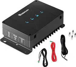
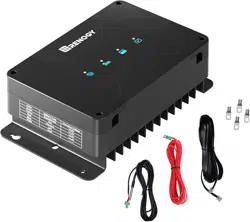
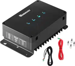
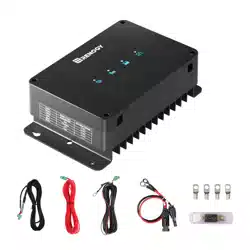
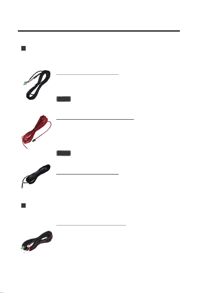
Package Contents
Renogy 12V 30A/50A Dual Input DC-DC On-
Board Battery Charger with MPPT x 1
User Manual × 1
VERSION B1
Dual Input DC-DC On-Board Battery Charger with MPPT
Renogy
12V 30A/50A
USER MANUAL
Renogy Temperature Sensor × 1
Solar Adapter Cable
(Terminal ring to MC4 Adapter Cable)
40A or 60A ANL FUSE (Output terminal) IGN Signal Wire x 1
Package Contents
08
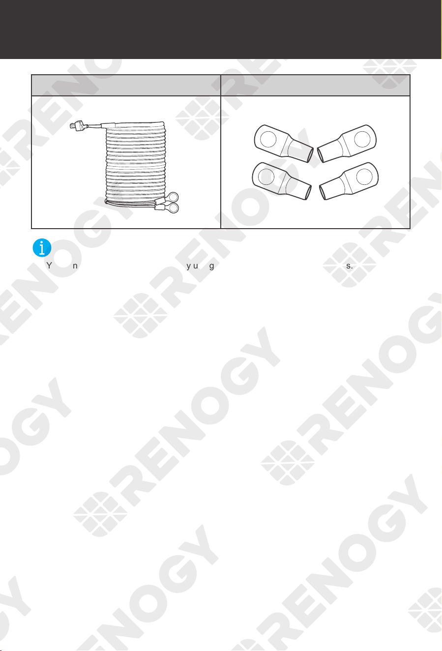
Voltage Sensor × 1 Ring Terminals (M8) × 4
NOT
E
z
You can customize adapter cables by using the included four M8 ring terminals.
Package Contents Optional Accessories
09
Optional Accessories
NOT
E
z
You can buy optional accessories from renogy.com.
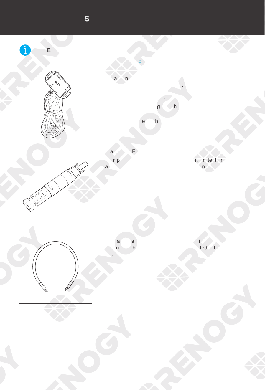
Bluetooth Module
LINK
POWER
2
Renogy BT-2 Bluetooth Module
With a Renogy BT-2 Bluetooth Module (sold separately), the
battery charger can be connected to the DC Home app for
remote device monitoring.
The battery charger supports bluetooth for system monitoring
and parameter modifying with the Renogy BT-2 Bluetooth
Module.
Scan the QR code on the last page of the user manual to
download the DC Home app.
Solar Panel Fuse
Solar panel fuse provides single circuit protection for solar
panels, preventing damage from high currents.
Fuse Cable
The cable is integrated with copper rings at both ends,
enabling the battery charger to be connected with an external
fuse.
Product Overview
10
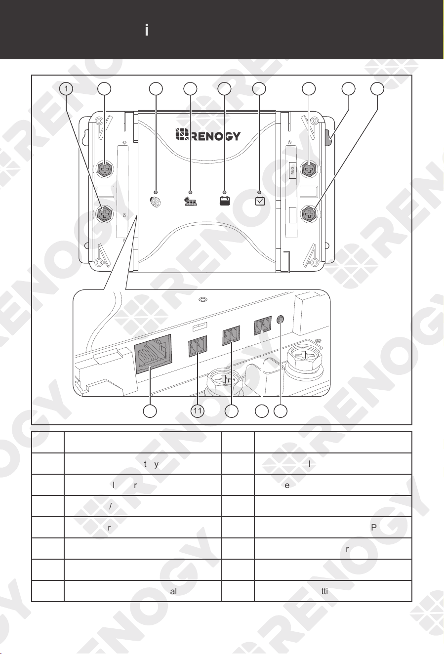
Product Overview
BTSRS485
ALT+
IGNBVS
PV+
BATT
TYPE
OUT+ NEG-
1 3 4 5 62 8 97
1211 13 1410
No. Part No. Part
1 Positive Starter Battery Terminal 8 Mounting Hole
2 Positive Solar Terminal 9 Positive House Battery Terminal
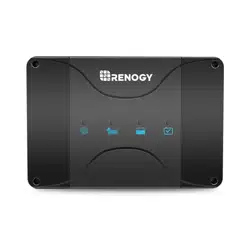
3 Alternator / Charging Indicator 10 RS485 Communication Ports
4 Solar Charging Indicator 11 Battery Temperature Sensor Port
5 Auxiliary Battery Indicator 12 Battery Voltage Sensor Port
6 Battery Type Indicator 13 Ignition Signal
7 Negative Common Terminal 14 Battery Type Setting Knob
Product Overview Wiring Diagram
11
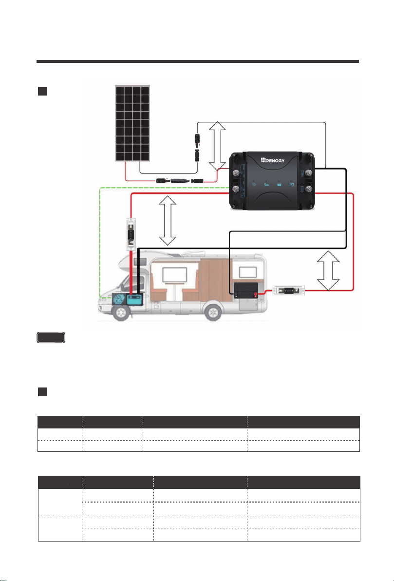
Wiring Diagram
BTSRS485
ALT+
IGNBVS
PV+
BATT
TYPE
OUT+ NEG-
Solar Panel
Negative
Positive
-
+
Auxiliary Battery
++
Starter Battery
Solar Panel Fuse
ANL FUSE ANL FUSE
+
Recommended Cable and Fuse Sizing
12
Recommended Cable and Fuse Sizing
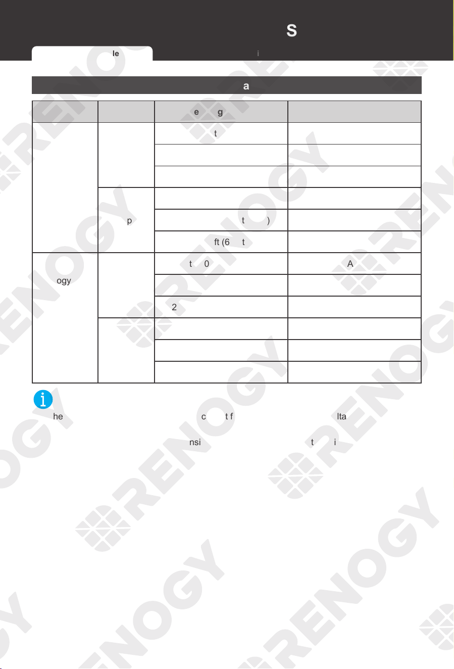
Recommended Cable Sizing
Model Cable Cable Length (ft) / (m) Recommended Cable Size
Renogy 12V
30A Dual
Input DC-
DC On-
Board Battery
Charger
with MPPT
(RBC30D1S)
Input
0 ft to 10 ft (0 m to 3 m) 8 AWG to 10 AWG
11 ft to 20 ft (3 m to 6 m) 4 AWG to 6 AWG
21 ft to 30 ft (6 m to 9 m) 4 AWG
Output
0 ft to 10 ft (0 m to 3 m) 8 AWG to 10 AWG
11 ft to 20 ft (3 m to 6 m) 4 AWG to 6 AWG
21 ft to 30 ft (6 m to 9 m) 4 AWG
Renogy 12V
50A Dual
Input DC-
DC On-
Board Battery
Charger
with MPPT
(RBC50D1S)
Input
0 ft to 10 ft (0 m to 3 m) 8 AWG
11 ft to 20 ft (3 m to 6 m) 6 AWG
21 ft to 30 ft (6 m to 9 m) 4 AWG
Output
0 ft to 10 ft (0 m to 3 m) 8 AWG
11 ft to 20 ft (3 m to 6 m) 6 AWG
21 ft to 30 ft (6 m to 9 m) 4 AWG
NOT
E
z
The cable specifications listed above account for critical, less than 3% voltage drop and may
not account for all configurations.
z
The specification of fuse cable is consistent with the input or output terminal of the battery
charger.
Recommended Cable Sizing Recommended Fuse Sizing

Recommended Cable and Fuse Sizing Recommended Cable and Fuse Sizing
13
Recommended Fuse Sizing
For your safety, it is recommended to install fuses at both the input and output ends of the battery
charger to ensure safe operations.
NOT
E
z
The specifications of the fuse are determined by the solar panel and battery charger
parameters.
z
The output fuse is included in the accessories supplied with the battery charger.
Fuse from Solar Panel to Battery Charger
Solar Panel to Battery Charger Fuse = Solar Panel / Solar Panel Array Total Amps * 1.56
Solar Panels in Series Solar Panels in Parallel
Total Amps: Isc
1
= Isc
2
= Isc
3
Fuse = Isc
1
* 1.56
Total Amps: Isc
1
+Isc
2
+Isc
3
Fuse = (Isc
1
+Isc
2
+Isc
3
) * 1.56
INF
O
z
Read the user manual of the solar panel to obtain working voltage parameters, and calculate
the corresponding fuse specifications according to the formula.
NOT
E
z
In the formula, Isc represents the rated current of the solar panel, and 1, 2 or 3 represents the
solar panel number, respectively.
Fuse from Starter Battery to Battery Charger
Renogy 12V 30A Dual Input DC-DC On-Board Battery Charger with
MPPT (RBC30D1S)
45-60A
Renogy 12V 50A Dual Input DC-DC On-Board Battery Charger with
MPPT (RBC50D1S)
75-100A
Recommended Cable Sizing Recommended Fuse Sizing
Components & Tools
14
Components & Tools
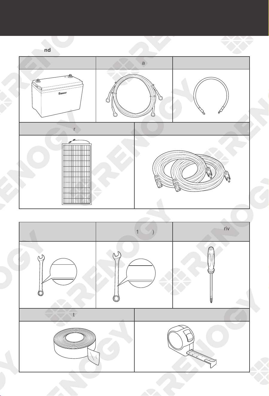
Recommended Components
Auxiliary Battery Ring Terminals Adapter Cable Fuse Cable
+
-
Solar Panel Solar Panel Extension Cables
Required Tools
Wrench (10 mm) Wrench (14 mm)
Phillips Screwdriver
(#2)
10mm
10mm
10 mm
14mm
14mm
14 mm
Insulation Tape Measuring Tape
3
4
5
6
Components & Tools Preparation
15
Preparation
NOT
E
z
The adapter cable used in this manual can be made by yourself or purchased from renogy.
com according to the names in Recommended Components.
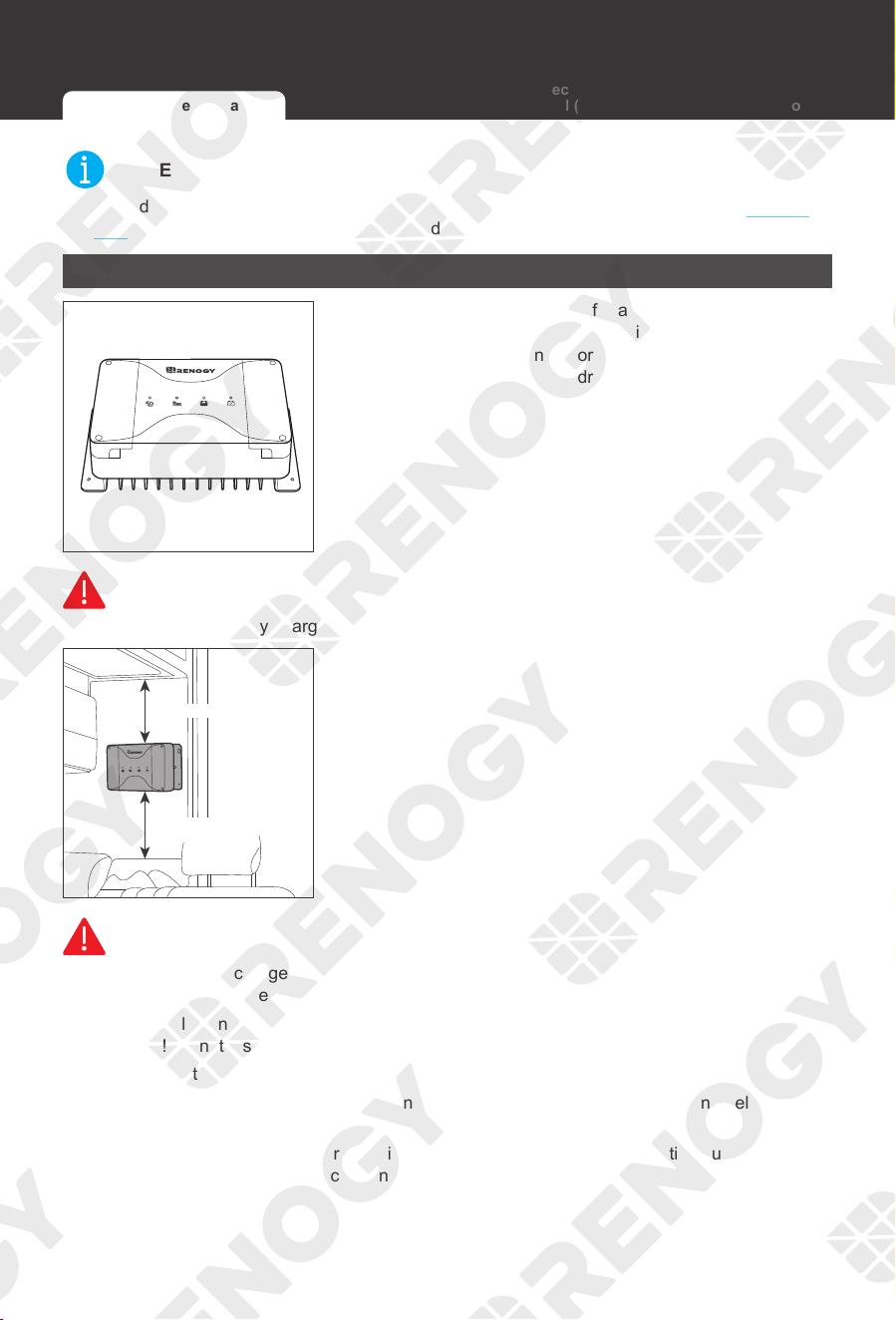
Checking Battery Charger
1. Inspect the battery charger for any visible damage
including cracks, dents, deformation, and other visible
abnormalities. All connector contacts shall be clean, free
of dirt and corrosion, and dry.
WARNIN
G
z
Do not use the battery charger if it has any visible damage.
≥6 in / 150 mm
≥6 in / 150 mm
2. Confirm the installation location.
WARNING
z
Install the battery charger indoors and prevent its components from being exposed to direct
sunlight. Prevent water from entering the battery charger.
z
Risk of explosion! Never install the battery charger in a sealed enclosure with flooded
batteries! Do not install it in a confined area where battery gases can accumulate.
z
Place the battery charger on a vertical surface. Make sure there is good ventilation.
z
The battery charger requires at least 6 inches (150 mm) of clearance above and below for
good ventilation.
z
Make sure that the battery charger is installed in an environment with relative humidity
between 0% and 95% and no condensation.
Checking Battery Charger Checking Auxiliary Battery
Checking Solar
Panel (Optional)
Checking Automobile
Alternator (Optional)

Preparation
16
-
3. Measure whether the
adapter cable is long
enough to connect
the battery charger.
NOT
E
z
If the adapter cable is not long enough, you can use an extension cable or reselect the
position where the battery charger needs to be secured.
4. Remove the four screws on the protective cover and
remove the cover with a phillips screwdriver.
Checking Auxiliary Battery
+
-
1. Inspect the auxiliary battery for any visible damage
including cracks, dents, deformation, and other visible
abnormalities. All connector contacts shall be clean, dry,
and free of dirt and corrosion.
CAUTIO
N
z
The battery charger can only be applied to a deep-cycle sealed lead-acid battery, a flooded
battery, an AGM battery, a gel battery or a lithium iron phosphate battery.
z
The battery may produce explosive gases when being charged. Make sure there is good
ventilation.
Checking Battery Charger Checking Auxiliary Battery
Checking Solar
Panel (Optional)
Checking Automobile
Alternator (Optional)
Preparation Preparation
17
z
Take care to use a high-capacity lead-acid battery. Be sure to wear protective goggles. If
carelessly getting electrolyte in your eyes, flush your eyes with clean water immediately.
WARNIN
G
z
Do not use the battery if it has any visible damage.
z
Do not touch the exposed electrolyte or powder if the battery housing is damaged.
System Voltage
Battery / Battery pack system voltage =
System voltage U
Batterys in Series Batterys in Parallel
System Voltage U:
U
1
+U
2
+U
3
System Voltage U:
U
1
=U
2
=U
3
2. The batteries can be combined in parallel
or in series as needed. This battery charger
supports a maximum system voltage of
16V. Read the user manual for battery
voltage parameters, and calculate the
battery or battery pack system voltage
according to the formula to ensure that it
does not exceed 16V.
NOT
E
z
In the formula, U represents the battery voltage, and 1, 2 or 3 represents the battery number,
respectively.
WARNIN
G
z
Do not use the battery charger if the battery or battery pack system voltage exceeds 16V.
Doing so will cause damage to the battery charger.
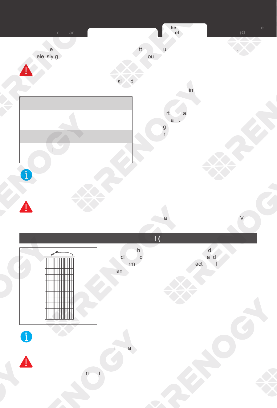
Checking Solar Panel (Optional)
1. Inspect the solar panel for any visible damage
including cracks, dents, deformation, and other visible
abnormalities. All connector contacts shall be clean, dry,
and free of dirt and corrosion.
NOT
E
z
The solar panels can be combined in parallel or in series as needed.
WARNIN
G
z
Do not use the solar panel if it has visible damage.
Checking Battery Charger Checking Auxiliary Battery
Checking Solar
Panel (Optional)
Checking Automobile
Alternator (Optional)

Preparation
18
z
Cover the solar panels or turn them over before connecting them to the battery charger.
Working Voltage
Working Voltage of Solar Panel / Solar
Panel Array =
Working Voltage U
Solar Panels in
Series
Solar Panels in
Parallel
Working Voltage U:
U
1
+U
2
+U
3
Working Voltage U:
U
1
=U
2
=U
3
2. Read the user manual of the solar panel
for the working voltage, and calculate the
working voltage of solar panel / solar panel
array according to the formula.
NOT
E
z
In the formula, U represents the working voltage of the solar panel, and 1, 2 or 3 represents
the solar panel number, respectively.
WARNING
z
Ensure that the working voltage of the solar panel / solar panel array does not exceed 15V.
z
For a 30A battery charger, ensure that the working voltage of the solar panel / solar panel
array does not exceed 30V. For a 50A battery charger, ensure that the working voltage of the
solar panel / solar panel array does not exceed 50V.
Maximum Output Power
Maximum Output Power of Solar Panel /
Solar Panel Array=
Maximum Output Power W
Solar Panels in
Series
Solar Panels in
Parallel
Maximum Output
Powe W: W
1
+W
2
+W
3
Maximum Output
Powe W: W
1
+W
2
+W
3
3. Read the user manual of the solar panel for
the maximum output power, and calculate
the maximum output power of solar panel
or solar panel array according to the
formula.
NOT
E
z
In the formula, W represents the maximum output power of the solar panel, and 1, 2, or 3
represents the solar panel number, respectively.
WARNIN
G
z
For a 30A battery charger, ensure that the maximum output power of the solar panel does not
exceed 400W. For a 50A battery charger, ensure that the maximum output power of the solar
panel does not exceed 660W.
Checking Battery Charger Checking Auxiliary Battery
Checking Solar
Panel (Optional)
Checking Automobile
Alternator (Optional)
Preparation Preparation
19
Checking Automobile Alternator (Optional)
The automobile alternator may be a smart alternator or a traditional alternator.
The connection method of a smart alternator or a traditional alternator depends on its parameters.
Before installing the battery charger, read the user manual of the vehicle or consult the vehicle
supplier to determine the type of alternator.
In addition, you can use a multimeter by yourself to measure the alternator to determine the type
of alternator.
1. Locate your main vehicle battery or the starter battery.
2. Start the engine. Ensure all any fans, radio, lights, and others are turned off.
3. Take a voltage reading across the main vehicle battery.
4. Leave the engine running for around 5 or 10 minutes, then repeat step 3.
If your readings are around 14.4V DC, then you most likely have a traditional alternator.
If your readings are around 12.5-13.5V, then you most likely have a smart alternator.
WARNIN
G
z
In general, the working voltage of a traditional alternator ranges from 13.2V to 16V, and that of
a smart alternator ranges from 12V to 16V.
z
For a 30A battery charger, ensure that the maximum output power of the alternator does
not exceed 400W. For a 50A battery charger, ensure that the maximum output power of the
alternator does not exceed 660W.
To prevent overuse of the starter battery, it is essential to select the battery charger specification.
The specification of the battery charger is no greater than 1.5-2 times the specification of the
alternator.
The battery charger and the alternator are both specified in A (amperage), for example:
The specification of RBC30D1S is 30A and that of a alternator is 45A-60A.
The specification of RBC50D1S is 50A and that of a alternator is 75A-100A.
Checking Battery Charger Checking Auxiliary Battery
Checking Solar
Panel (Optional)
Checking Automobile
Alternator (Optional)

Battery Charger Wiring
20
Battery Charger Wiring
CAUTIO
N
z
Do not overtorque the terminals on the battery charger.
z
Do not connect the positive terminal first.
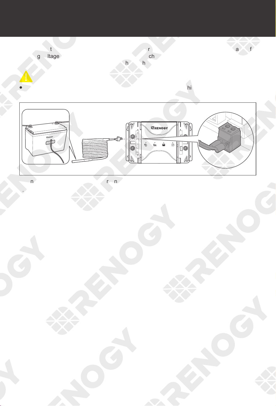
1. NEG- Terminal Wiring:
BTSRS485
ALT+
IGNBVS
PV+
BATT
TYPE
OUT+ NEG-
Connect the auxiliary battery to (NEG-) terminal of the battery charger.
NOT
E
z
Connect the negative terminal of the solar panel and the negative terminal of the starter battery to
the negative pole of the auxiliary battery.
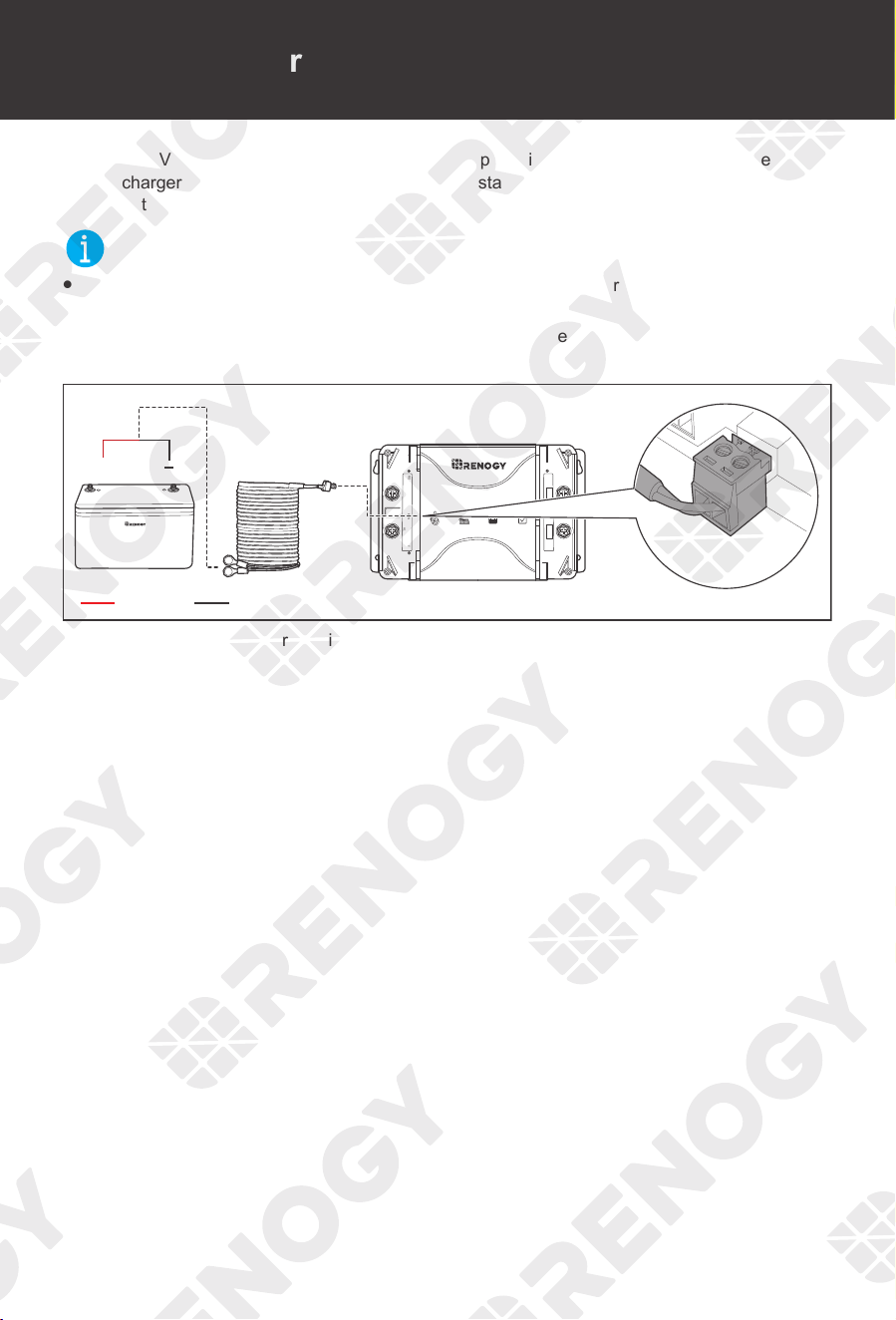
2. Auxiliary Battery Positive Wiring:
BTSRS485
ALT+
IGNBVS
PV+
BATT
TYPE
OUT+ NEG-
-
+
+
Positive
BTSRS485
ALT+
IGNBVS
PV+
BATT
TYPE
OUT+ NEG-
Connect the positive terminal of the auxiliary battery to one end of the fuse box. Connect the other
end of the fuse box to the OUT+ terminal of the battery charger. Make sure all the terminals are
tight and secure.
Battery Charger Wiring Battery Charger Wiring
21
3. Solar Positive Wiring:
BTSRS485
ALT+
IGNBVS
PV+
BATT
TYPE
OUT+ NEG-
PV+
RS485
BTS BV
Connect the positive terminal of the solar panel to the Positive Solar Terminal (PV+) of the battery
charger.
4. ALT Positive Wiring:
BTSRS485
ALT+
IGNBVS
PV+
BATT
TYPE
OUT+ NEG-
ALT+
IGN
BVS BATT
TYPE
Connect the positive terminal of the starter battery to the Positive Starter Battery Terminal (ALT+).
5. For smart alternator only:
BTSRS485
ALT+
IGNBVS
PV+
BATT
TYPE
OUT+ NEG-
Insert the terminal block of the IGN Signal Wire to the Ignition Signal (IGN), and the bare wire
terminal to the ignition of the vehicle.
NOT
E
z
The traditional alternator does not need to be connected to the IGN Signal Wire.
Mounting
22
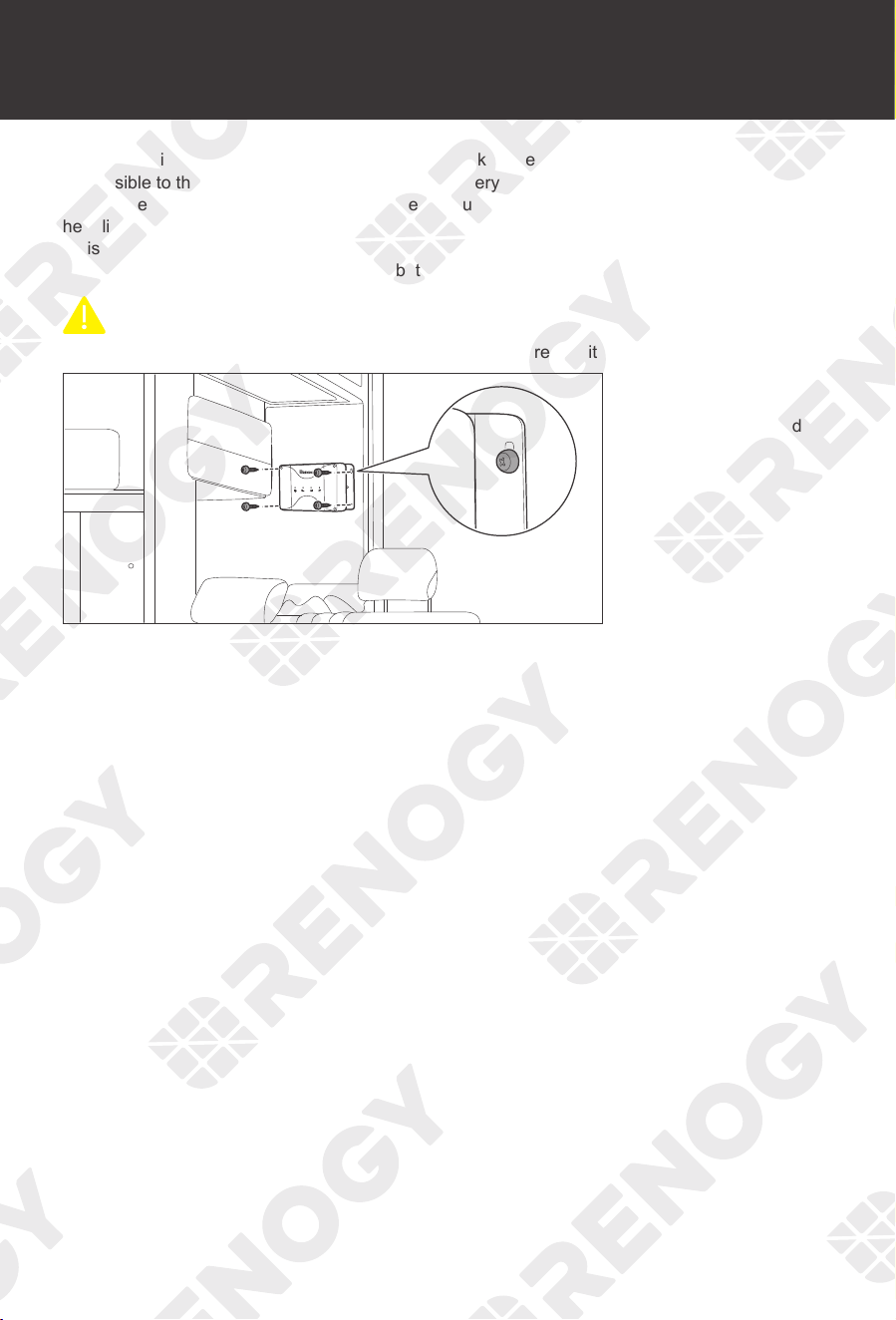
Mounting
When selecting a location for the battery charger, make sure that the battery charger is as close
as possible to the battery (auxiliary battery). The battery charger can be installed in the cabin of
the vehicle, along the chassis rails, in the internal guard panel of the vehicle, behind the grille or
headlights, or even on the side of the radiator. However, ensure that the area is not susceptible to
moisture or other substances as well as potential high temperatures. It is recommended to ensure
good ventilation for better operation of the battery charger.
CAUTIO
N
z
Make sure that the battery charger is installed firmly to prevent it from falling off.
Place the battery charger
against a flat surface and
secure it with included
screws.
Mounting Temperature Sensor
23
Temperature Sensor
The temperature sensor can detect the battery temperature and update it to the battery charger for
charging voltage calibration. This ensures the battery charger (with operating temperature range
from -31
°
F to 149
°
F or -35
°
C to 65
°
C) can charge the battery normally.
CAUTIO
N
z
Do not use the temperature sensor on a LiFePO4 (LFP) battery which comes with a battery
management system (BMS).
+
-
BTSRS485
ALT+
IGNBVS
PV+
BATT
TYPE
OUT+ NEG-
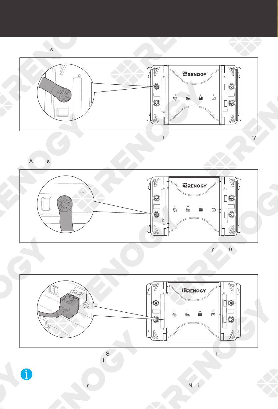
1. Insert the temperature sensor terminal block into the BTS port of the battery charger.
2. Adhere the sensor on the top or side of the battery with insulation tape.
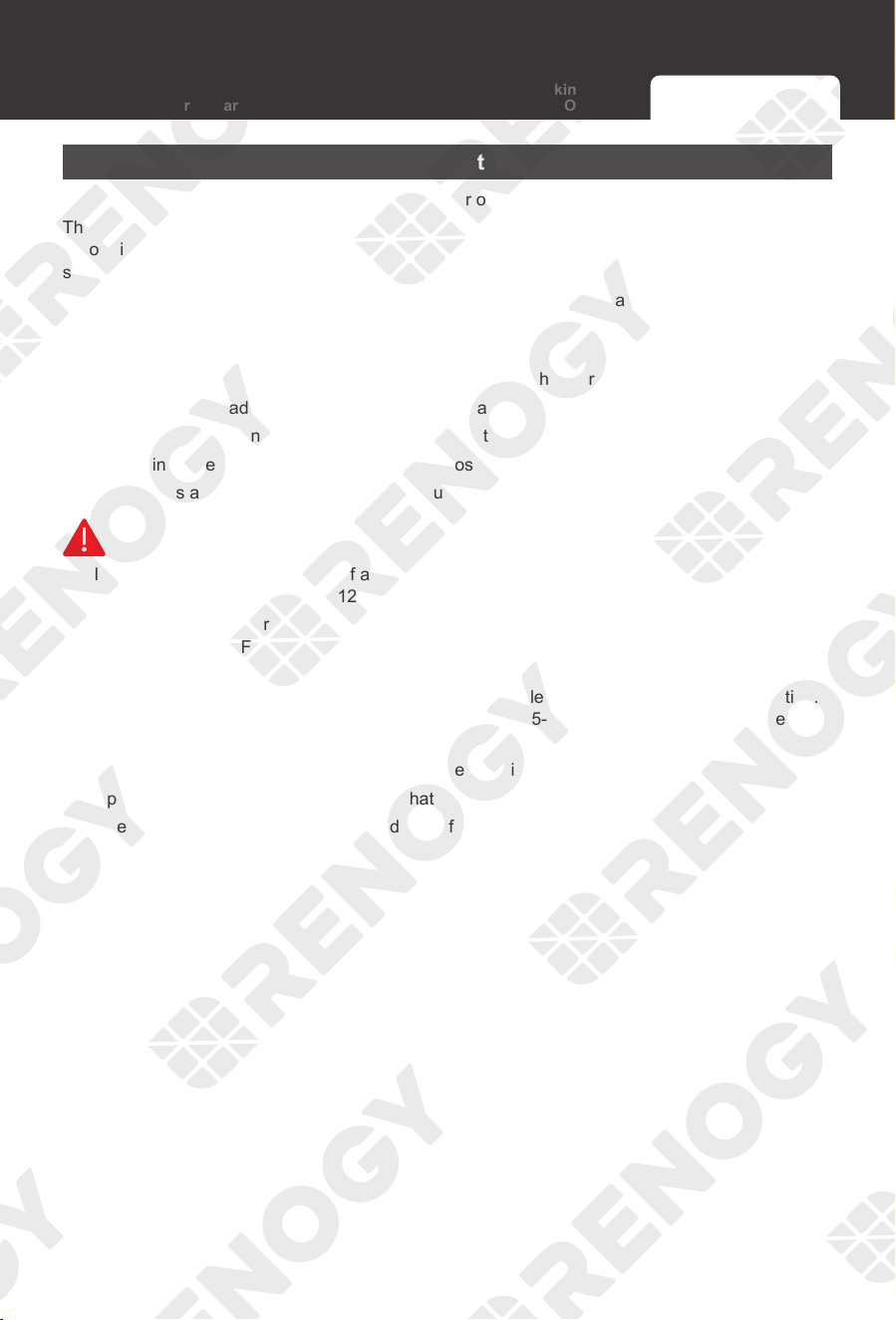
Voltage Sensor
24
Voltage Sensor
The Battery Voltage Sensor is the perfect solution by providing an accurate battery voltage to the
battery charger and allowing it to adjust the charging stage precisely resulting in overall extension
of your battery life.
NOT
E
z
Identify the polarities (positive and negative) on the cables used for the batteries. A reverse
polarity contact may damage the battery charger.
z
The voltage sensor ring terminal is M8 (Approx. 5/16''). If the battery bolt size is small, use a
gasket to fix it to prevent it from falling off.
BTSRS485
ALT+
IGNBVS
PV+
BATT
TYPE
OUT+ NEG-
-
+
+
Negative
Positive
1. Insert the voltage sensor terminal block to the BVS port.
2. Connect the voltage sensor ring terminal to the positive and negative poles of the battery
system.
Voltage Sensor Communication
25
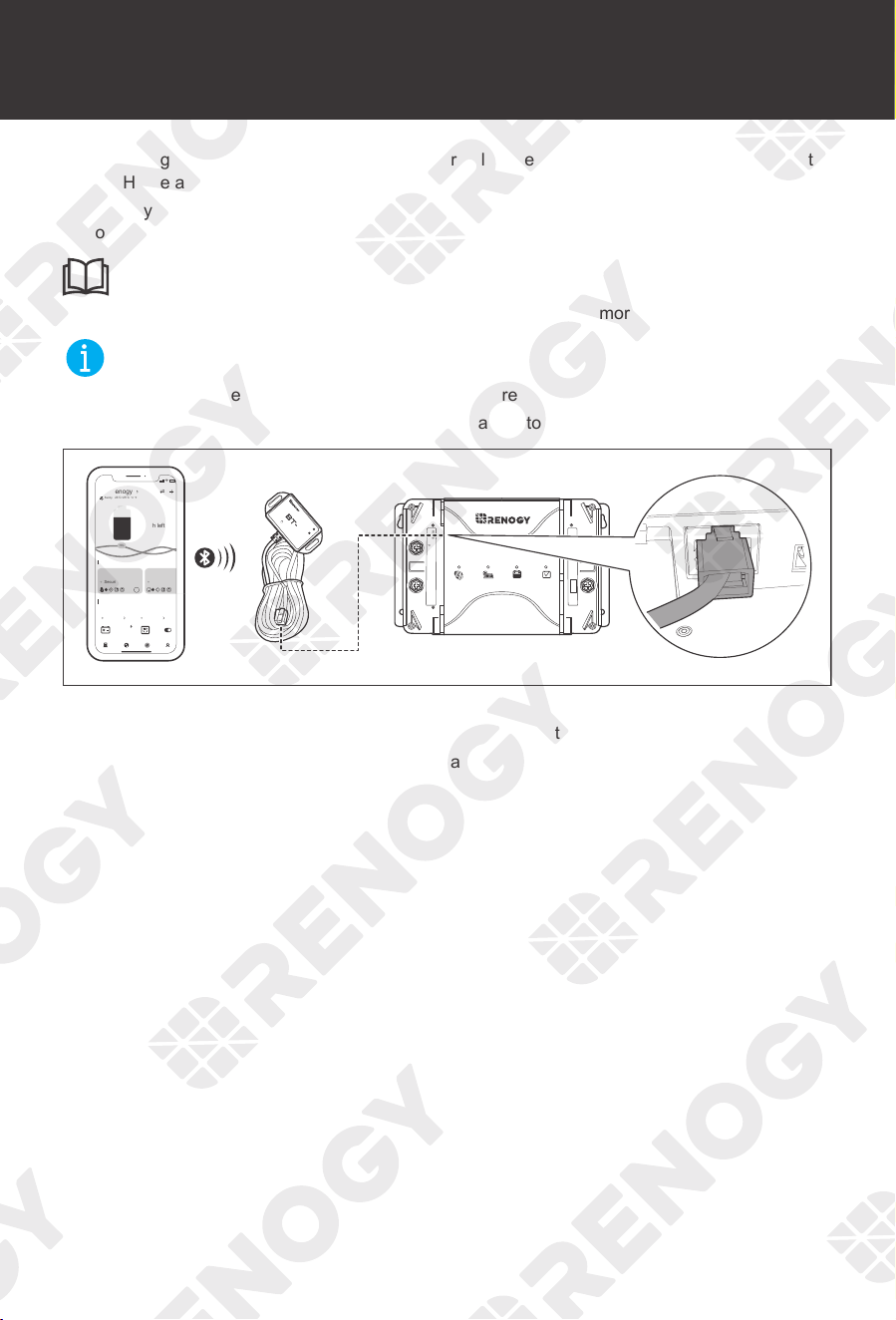
Communication
With a Renogy BT-2 Bluetooth Module (sold separately), the battery charger can be connected to
the DC Home app for remote device monitoring.
The battery charger supports bluetooth for system monitoring and parameter modifying with the
Renogy BT-2 Bluetooth Module.
INF
O
z
Read the user manual of the Renogy BT-2 Bluetooth Module for more instructions.
NOT
E
z
Make sure that the battery charger is turned on before connection.
z
Scan the QR code on the last page of the uesr manual to download the DC Home app.
BTSRS485
ALT+
IGNBVS
PV+
BATT
TYPE
OUT+ NEG-
Bluetooth Module
LINK
POWER
2
My Renogy
10
Security
FUN
B
Commonly
Sunny
h left
9:41
23°C~25°C
°C °F
RBT 1000 HJD
90%
1000Ah
RBT 1000 HJD
Night
Devices
Battery Zigbee Socket
75%
Device Search
Community
Personal
B
1. Power on the battery charger.
2. Connect the Bluetooth Module to the RS485 port on the bottom of the battery charger.
3. Connect the battery charger to the DC Home app.
Operation
26
Operation
Manually set the battery type according to needs. The knob with 5 gears makes the selection of
battery type more convenient.
In the DC Home app, you can also set the battery type. Check the operating status of the battery
charger and modify some parameters. If you need to program multiple parameters of the battery,
you can set the battery type in the user mode.
Selecting the Battery Type
WARNIN
G
z
Refer to battery manufacturer technical specifications when choosing a preset battery.
Incorrect battery type selection resulting in damage will not be covered by warranty.
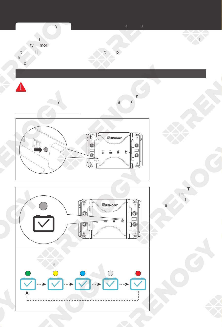
Battery Type Setting Button
BTSRS485
ALT+
IGNBVS
PV+
BATT
TYPE
OUT+ NEG-
1. Press the Battery
Type Setting Knob on
the left side.
SLA (Default)
Sealed Lead
Acid Battery
GEL
Gel Battery
Li
Lithium Battery
User
Custom Battery
FLD
Flooded Battery
BTSRS485
ALT+
IGNBVS
PV+
BATT
TYPE
OUT+ NEG-
2. The Battery Type
Indicator flashes
different colors to
represent different
types of battery.
Selecting the Battery Type Battery Charging Parameters User Mode
Operation Operation
27
DC Home app
NOT
E
z
Make sure the Bluetooth of your phone is turned on.
z
The version of the DC Home app might have been updated. Illustrations in the user manual
are for reference only. Follow the instructions based on the current app version.
My Renogy
Can be used for
Rain Shower
24.4°C~27.2°C °C °F
Fully charged in
No device yet...
Device
Community
Personal
h
h
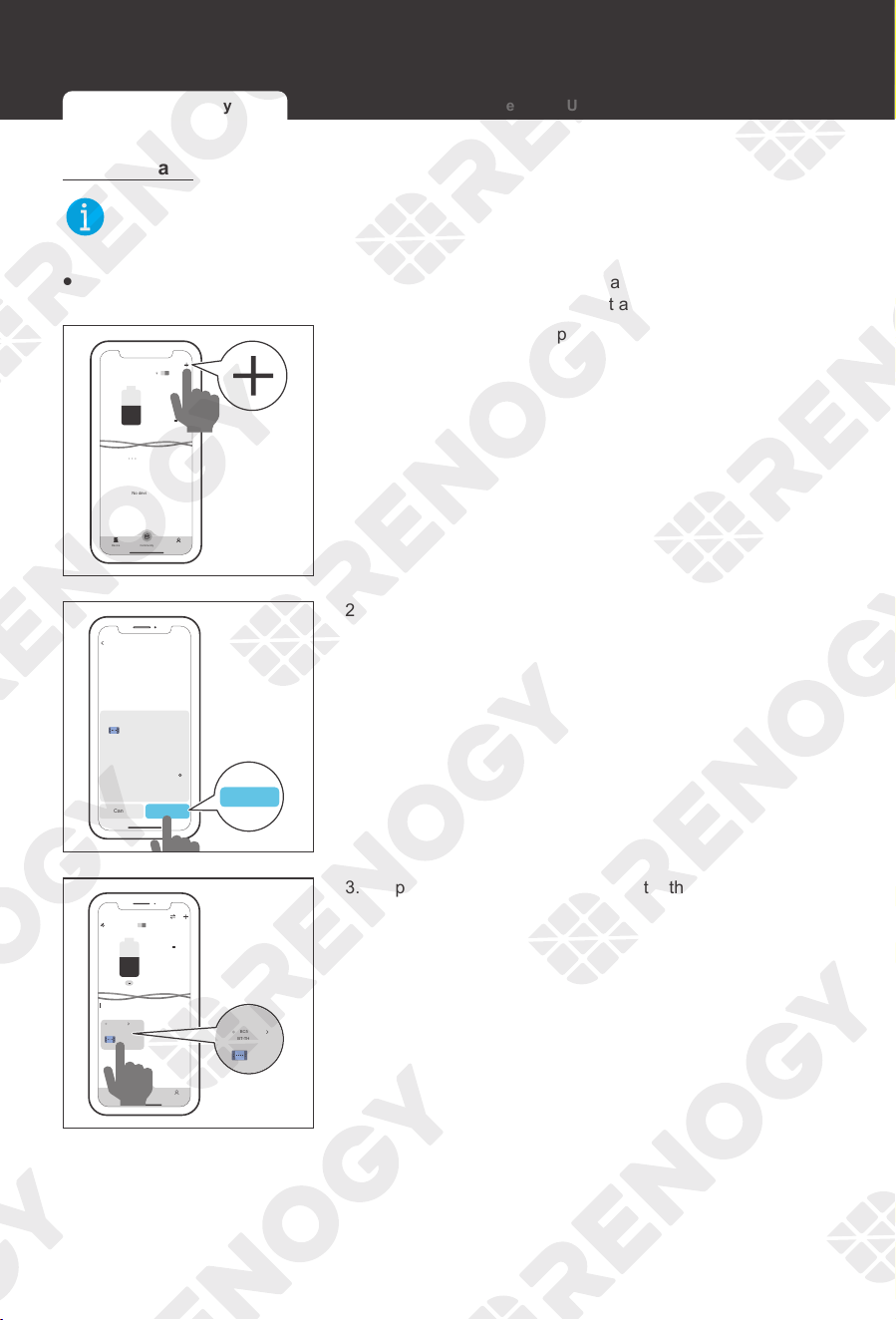
1. Open the DC Home app. Tap + to search for new devices.
HUB Mode
Searching for device
Please make sure your phone’s Bluetooth is
turned on properly; the device is running
properly and the device’s Bluetooth is
working properly.
Cancel Confirm
RBC50D1S-G1
BT-TH-E32E068D
DCC
Found Devices
Confirm
Confirm
2. Tap Confirm to add the newly found device to the device
list.
My Renogy
Can be used for
DCDC
BT-TH-E32E068D
Device
Sunny
46°F~66°F
°C °F
h
Device
Community
Personal
RBC50D1S-G1
DCC
BT-TH-E32E068D
RBC50D1S-G1
3. Tap the battery charger area to enter the device
information interface.
Selecting the Battery Type Battery Charging Parameters User Mode
Operation
28
RBC50D1S-G1
NOT CHARGING
Battery Type
House Battery Volts
Starter Battery Volts
0
A
0
v
13.1
v
User
0
A
0
A
0
W
0
KWh
77.00
69.80
Starter Battery Amps
House Battery Charging Amps
PV Charging Amps
House Battery Charging Watts
Total KWh Generated
House Battery Temperature
DC-DC MPPT Temperature
...
°C °F
°C °F
Settings
History
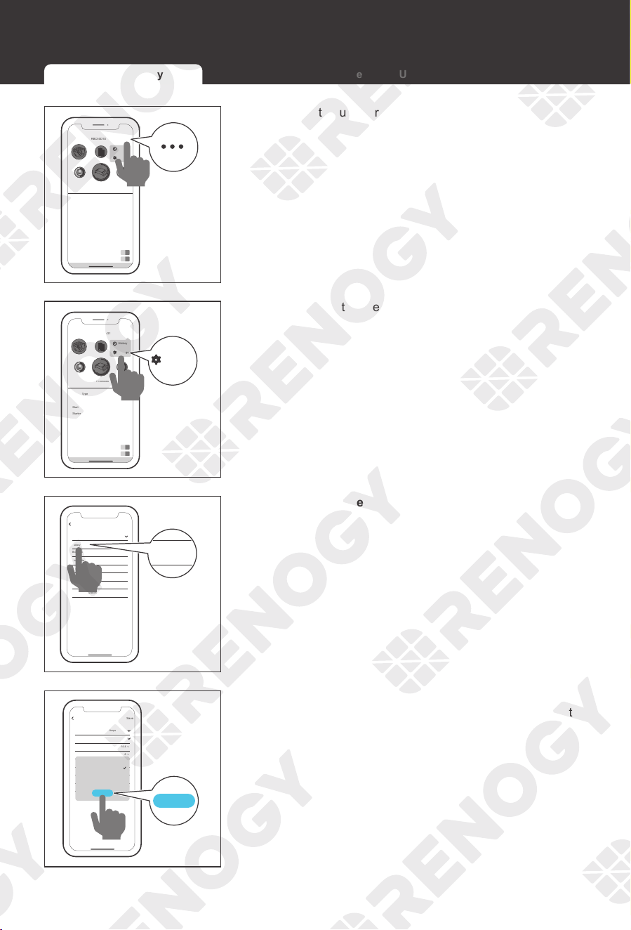
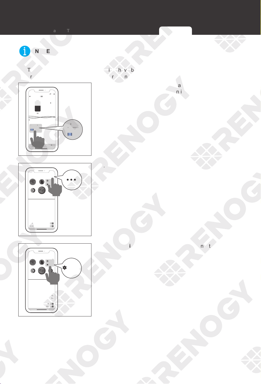
4. Tap ••• in the upper right corner.
RBC50D1S-G1
NOT CHARGING
Battery Type
House Battery Volts
Starter Battery Volts
0
A
0
v
13.1
v
User
0
A
0
A
0
W
0
KWh
77.00
69.80
Starter Battery Amps
House Battery Charging Amps
PV Charging Amps
House Battery Charging Watts
Total KWh Generated
House Battery Temperature
DC-DC MPPT Temperature
...
°C °F
°C °F
Settings
History
Settings
5. Tap Settings to enter the mode selection interface.
RBC50D1S-G1
Maximum Combined Charging Amps
Battery Type
Boost Voltage (13.2V-15.5v)
Float Voltage (13.2V-15.5V)
Equalization Voltage (13.2V-15.5V)
Boost Duration (0-120 min)
Equalization interval (0-30 Days)
Equalization Duration (0-120 min)
50
User
14.4 v
13.8 v
14.6 v
120 min
30 Days
120 min
Save
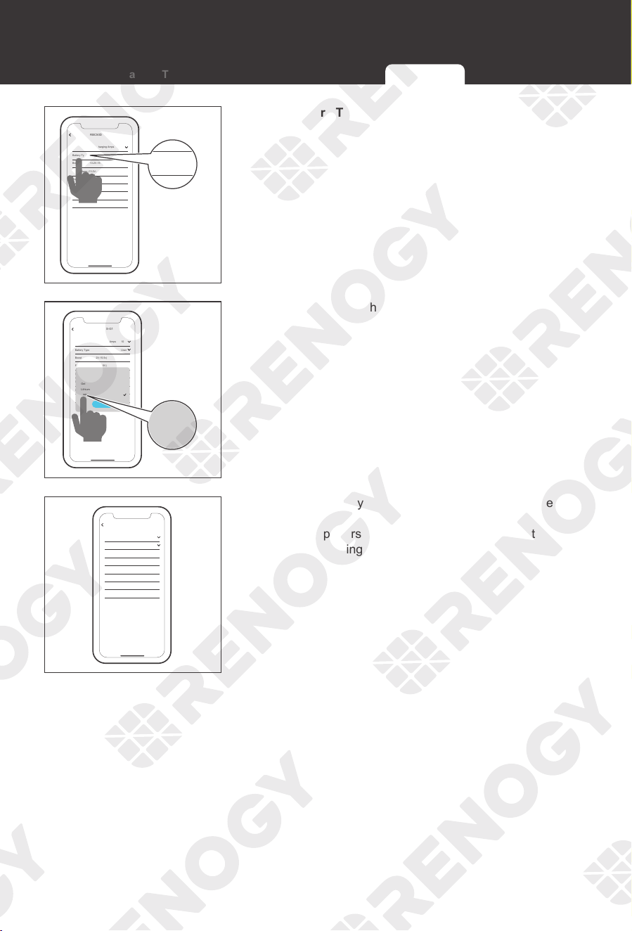
Maximum Combined Charging Amps
Battery Type
Boost Voltage (13.2V-15.5v)
6. Tap Battery Type.
RBC50D1S-G1
Maximum Conbined Charging Amps
Battery Type
Boost Voltage (13.2V-15.5v)
Float Voltage (13.2V-15.5V)
Equalization Volitage (13.2V-15.5V)
Boost Duration (0-120 min)
Equalization interval (0-30 Days)
Equalization Duration (0-120 min)
10
User
14.4 v
13.8 v
14.6 v
120 min
30 Days
120 min
Save
Flooded
Sealed/AGM
Gel
Lithium
User
Confirm
Confirm
7. According to the actual usage, tap the option button that
matches the auxiliary battery in this interface to complete
the battery type setting.
Selecting the Battery Type Battery Charging Parameters User Mode
Operation Operation
29
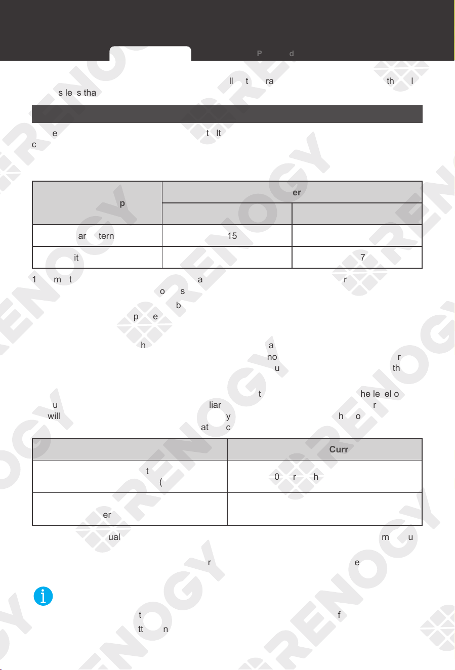
Battery Charging Parameters
WARNIN
G
z
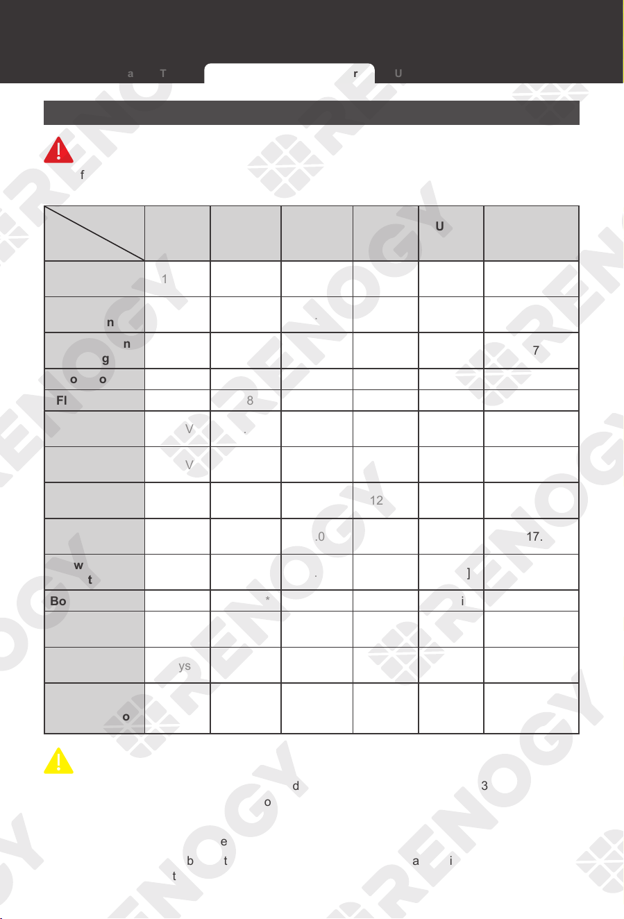
Before modifying battery parameters, check the table below. Incorrect parameter setting will
damage the device and void the warranty.
Battery
Type
Parameters
AGM /
SLD
Gel Flooded Li (LFP)
User-
defined
User Setting
Range
Overvoltage
Shutdown
16.0V 16.0V 16.0V 16.0V 16.0V 9.0-17.0V
Overvoltage
Return
15.0V 15.0V 15.0V 15.4V [15.4V] ―
Equalization
Voltage
― ― 14.8V ― 14.6V 9.0-17.0V
Boost Voltage 14.6V 14.2V 14.6V 14.4V 14.4V 9.0-17.0V
Float Voltage 13.8V 13.8V 13.8V ― 13.8V 9.0-17.0V
Boost Return
Voltage
13.2V 13.2V 13.2V 13.2V 13.2V 9.0-17.0V
Low Voltage
Reconnect
12.6V 12.6V 12.6V 12.6V [12.6V] 9.0-17.0V
Undervoltage
Recover
12.2V 12.2V 12.2V 12.3V [12.2V] ―
Undervoltage
Warning
12.0V 12.0V 12.0V 12.1V 12.0V 9.0-17.0V
Low Voltage
Shutdown
11.1V 11.1V 11.1V 11.1V [11.1V] 9.0-17.0V
Boost Duration 120 min* 120 min* 120 min* ― 120 min* 10-300 min
Equalization
Duration
― 120 min* ― ― 120 min* 0-300 min
Equalization
Interval
0 days** 0 days** 28 days ― 30 days 0-250 days
Temperature
Compensation
-3
mV / ℃
/
2V
-3
mV / ℃ /
2V
-3
mV / ℃ /
2V
―
-3
mV / ℃ /
2V
0 / 3 / 4 / 5
mV / ℃ / 2V
CAUTIO
N
z
* if the battery type is lead-acid battery and the charging current is less than 3A, the battery
charger will automatically switch to float charging after 30 seconds.
z
** no Equalization Charging.
z
Parameters in gray cannot be set manually
z
Parameters in square brackets ([ ]) are automatically adjusted according to the relevant
settings, and cannot be set directly.
Selecting the Battery Type Battery Charging Parameters User Mode
Operation
30
User Mode
WARNIN
G
z
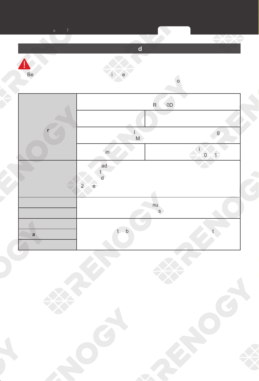
Before modifying battery parameters in user mode, check the table below and consult the
battery manufacturer to check whether modification is allowed. Incorrect parameter setting will
damage the device and void the warranty.
Maximum Charging
Current
Renogy 12V 30A Dual Input DC-DC On-Board Battery Charger with
MPPT (RBC30D1S)
Max. Charging Current: 30A
Adjustable Charging Current:
30A / 20A / 10A
Renogy 12V 50A Dual Input DC-DC On-Board Battery Charger with
MPPT (RBC50D1S)
Max. Charging Current: 50A
Adjustable Charging Current:
50A / 40A / 30A / 20A / 10A
Equalization Voltage
(1) For lead-acid batteries, please consult the battery manufacturer
to obtain the voltage value, and then set the balance voltage
according to the feedback.
(2) If equalization charging is not required, set the voltage to boost
voltage.
Boost Voltage
Please consult the battery manufacturer and check if this voltage
value needs to be set.
Float Voltage
Boost Duration
Please consult the battery manufacturer if it is necessary to set this
parameter value.
Equalization Interval
Equalization Duration
Selecting the Battery Type Battery Charging Parameters User Mode
Operation Operation
31
NOT
E
z
Make sure Bluetooth of your phone is turned on.
z
The version of the DC Home app might have been updated. Illustrations in the user manual
are for reference only. Follow the instructions based on the current app version.
My Renogy
Can be used for
DCDC
BT-TH-E32E068D
Device
Sunny
46°F~66°F
°C °F
h
Device
Community
Personal
RBC50D1S-G1
DCC
BT-TH-E32E068D
RBC50D1S-G1
1. Open the DC Home app and tap the battery charger area
to enter the device information interface.
RBC50D1S-G1
NOT CHARGING
Battery Type
House Battery Volts
Starter Battery Volts
0
A
0
v
13.1
v
User
0
A
0
A
0
W
0
KWh
77.00
69.80
Starter Battery Amps
House Battery Charging Amps
PV Charging Amps
House Battery Charging Watts
Total KWh Generated
House Battery Temperature
DC-DC MPPT Temperature
...
°C °F
°C °F
Settings
History
2. Tap ••• in the upper right corner.
RBC50D1S-G1
NOT CHARGING
Battery Type
House Battery Volts
Starter Battery Volts
0
A
0
v
13.1
v
User
0
A
0
A
0
W
0
KWh
77.00
69.80
Starter Battery Amps
House Battery Charging Amps
PV Charging Amps
House Battery Charging Watts
Total KWh Generated
House Battery Temperature
DC-DC MPPT Temperature
...
°C °F
°C °F
Settings
History
Settings
3. Tap Settings to enter the mode selection interface.
Selecting the Battery Type Battery Charging Parameters User Mode
Operation
32
RBC50D1S-G1
Maximum Combined Charging Amps
Battery Type
Boost Voltage (13.2V-15.5v)
Float Voltage (13.2V-15.5V)
Equalization Voltage (13.2V-15.5V)
Boost Duration (0-120 min)
Equalization interval (0-30 Days)
Equalization Duration (0-120 min)
50
User
14.4 v
13.8 v
14.6 v
120 min
30 Days
120 min
Save
Maximum Combined Charging Amps
Battery Type
Boost Voltage (13.2V-15.5v)
4. Tap Battery Type.
RBC50D1S-G1
Maximum Conbined Charging Amps
Battery Type
Boost Voltage (13.2V-15.5v)
Float Voltage (13.2V-15.5V)
Equalization Volitage (13.2V-15.5V)
Boost Duration (0-120 min)
Equalization interval (0-30 Days)
Equalization Duration (0-120 min)
10
User
14.4 v
13.8 v
14.6 v
120 min
30 Days
120 min
Save
Flooded
Sealed/AGM
Gel
Lithium
User
Confirm
Flooded
Sealed/AGM
Gel
Lithium
User
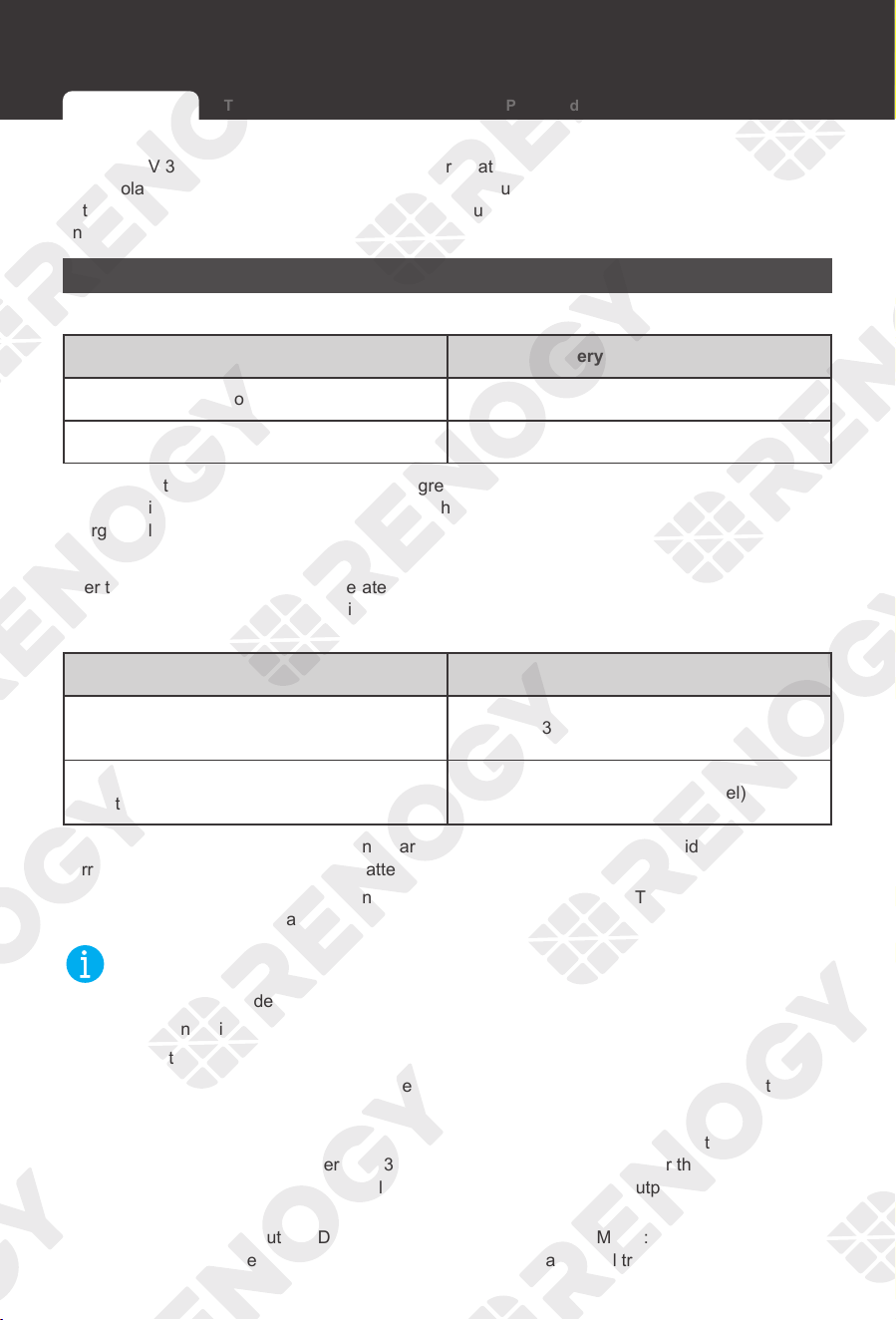
5. Tap User to enter the user-defined mode interface.
RBC50D1S-G1
Maximum Conbined Charging Amps
Battery Type
Boost Voltage (13.2V-15.5v)
Float Voltage (13.2V-15.5V)
Equalization Voltage (13.2V-15.5V)
Boost Duration (0-120 min)
Equalization interval (0-30 Days)
Equalization Duration (0-120 min)
50
User
14.4 v
13.8 v
14.6 v
120 min
30 Days
120 min
Save
6. In this interface, you can customize multiple parameters
of the battery. When the parameters are modified, Setting
Success appears on the interface, indicating that the
parameter setting is completed.
Selecting the Battery Type Battery Charging Parameters User Mode
Operation Working Logic
33
Renogy 12V 30A/50A Dual Input DC-DC On-Board Battery Charger with MPPT can be connected
to the solar panel and the automobile starter battery simultaneously or to the solar panel or the
automobile starter battery separately to charge the auxiliary battery. The charging logic depends
on the connection method.
To Solar Panel
▇
Working conditions
Solar Panel Voltage Battery Charger Status
≥15.0V, for 10 seconds Start Working
<15.0V Stop Working
When the output voltage of the solar panel is greater than or equal to 15V, the battery charger
starts working after 10s. If the output voltage of the solar panel is less than 15V, the battery
charger will stop working.
▇
Charging Logic
After the battery charger starts to operate, it determines the level of the auxiliary battery
automatically. If the auxiliary battery is not fully charged, the battery charger will charge the
auxiliary battery.
Model Charging Current
Renogy 12V 30A Dual Input DC-DC On-Board
Battery Charger with MPPT (RBC30D1S)
≤3
0A (from the solar panel)
Renogy 12V 50A Dual Input DC-DC On-Board
Battery Charger with MPPT (RBC50D1S)
≤
50A (from the solar panel)
Renogy 12V 30A Dual Input DC-DC On-Board Battery Charger with MPPT provides the maximum
current of 30A to charge the auxiliary battery.
Renogy 12V 50A Dual Input DC-DC On-Board Battery Charger with MPPT provides the maximum
current of 50A to charge the auxiliary battery.
NOT
E
z
The battery charger determines automatically that the auxiliary battery is fully charged if:
(1) The non-lithium battery enters float charging.
(2) The lithium battery maintains boost charging for 1 hour.
z
When the auxiliary battery is fully charged, the battery charger activates the standby state.
▇
Overvoltage protection
Renogy 12V 30A Dual Input DC-DC On-Board Battery Charger with MPPT: When the output
voltage of the solar panel is greater than 30.5V, the battery charger will trigger the overvoltage
protection and stop operating immediately, and will not operate until the output voltage of the solar
panel is less than 29.5V.
Renogy 12V 50A Dual Input DC-DC On-Board Battery Charger with MPPT: When the output
voltage of the solar panel is greater than 50.5V, the battery charger will trigger the overvoltage
Working Logic
To Solar Panel To Starter Battery To Both Solar Panel and Starter Battery
Working Logic
34
protection and stop operating immediately, and will not operate until the output voltage of the solar
panel is less than 49.5V.
To Starter Battery
As the automobile alternator may be a smart alternator or a traditional alternator, the working
conditions and charging logic of the battery charger depend on the connection method and the
working voltage depends on the alternator.
▇
Working conditions
Alternator Type
Starter Battery Voltage
Cut-in Cut-off
Smart Alternator >12.0V, for 15 seconds <11.5V
Traditional Alternator >13.2V, for 15 seconds <12.7V
1. Smart alternator: When the battery charger tests that the voltage of the starter battery is
greater than 12V, it pauses for 15s and then starts to work and charge the auxiliary battery.
2. Traditional alternator: When the battery charger tests that the voltage of the starter battery is
greater than 13.2V, it pauses for 15s and then starts to work and charge the auxiliary battery.
▇
Charging Logic
1. Smart alternator: After the battery charger starts to operate, it determines the level of the
auxiliary battery automatically. If the auxiliary battery is not fully charged, the battery charger
will charge the auxiliary battery. If the auxiliary battery is fully charged or the voltage of the
starter battery is less than 11.5V, the battery charger will stop operating.
2. Traditional alternator: After the battery charger starts to operate, it determines the level of the
auxiliary battery automatically. If the auxiliary battery is not fully charged, the battery charger
will charge the auxiliary battery. If the auxiliary battery is fully charged or the voltage of the
starter battery is less than 12.7V, the battery charger will stop operating.
Model Charging Current
Renogy 12V 30A Dual Input DC-DC On-Board
Battery Charger with MPPT (RBC30D1S)
≤3
0A (from the starter battery)
Renogy 12V 50A Dual Input DC-DC On-Board
Battery Charger with MPPT (RBC50D1S)
≤
50A (from the starter battery)
Renogy 12V 30A Dual Input DC-DC On-Board Battery Charger with MPPT provides the maximum
current of 30A to charge the auxiliary battery.
Renogy 12V 50A Dual Input DC-DC On-Board Battery Charger with MPPT provides the maximum
current of 50A to charge the auxiliary battery.
NOT
E
z
The battery charger determines automatically that the auxiliary battery is fully charged if:
(1) The non-lithium battery enters float charging.
To Solar Panel To Starter Battery To Both Solar Panel and Starter Battery
Working Logic Working Logic
35
(2) The lithium battery maintains boost charging for 1 hour.
z
When the auxiliary battery is fully charged, the battery charger activates the standby state.
▇
Overvoltage protection
When the voltage of the starter battery is greater than 16.5V, the battery charger triggers
overvoltage protection and stops operating immediately. The battery charger will not operate until
the voltage of the battery is less than 15.5V.
To Both Solar Panel and Starter Battery
When the input terminal of the battery charger is connected to the solar panel and the starter
battery at the same time, if the output voltage of the solar panel meets the working conditions of
the battery charger, the battery charger will charge the battery with the solar panel first.
If the solar panel fails to keep the auxiliary battery fully charged, the battery charger will adjust
automatically to allow both the solar panel and the starter battery to charge the auxiliary battery at
the same time.
Prioritizing the solar panel to generate electricity alone
▇
Working conditions
Model
Working
Condition
Starter battery
state
Solar Panel
Output
Current
Auxiliary
Battery
Voltage
Auxiliary
Battery
Charging
RBC30D1S
Separate
solar work
Smart: >12V
Traditional: >13.2V
≥15A
≥13.2V
•
Lithium
battery: boost
charging
•
Non-lithium
battery: float
charging
Smart: <11.5V
Traditional: <12.7V
RBC50D1S
Smart: >12V
Traditional: >13.2V
≥25A
Smart: <11.5V
Traditional: <12.7V
Renogy 12V 30A Dual Input DC-DC On-Board Battery Charger with MPPT: When the solar panel
provides more than 15A to charge the auxiliary battery and the voltage of the auxiliary battery is
greater than or equal to 13.2V, only the solar panel charges the battery charger.
Renogy 12V 50A Dual Input DC-DC On-Board Battery Charger with MPPT: When the solar panel
provides more than 25A to charge the auxiliary battery and the voltage of the auxiliary battery is
greater than or equal to 13.2V, only the solar panel charges the battery charger.
NOT
E
z
If both the solar panel and the starter battery fail to meet the working conditions, the battery
charger will stop operating.
To Solar Panel To Starter Battery To Both Solar Panel and Starter Battery
Working Logic
36
▇
Charging Logic
1. Charging the auxiliary battery: After the battery charger starts to operate, it determines the
level of the auxiliary battery automatically. If the auxiliary battery is not fully charged, the
battery charger charges it only.
Model Charging Current
Renogy 12V 30A Dual Input DC-DC On-Board
Battery Charger with MPPT (RBC30D1S)
≤3
0A (from the solar panel)
Renogy 12V 50A Dual Input DC-DC On-Board
Battery Charger with MPPT (RBC50D1S)
≤
50A (from the solar panel)
Renogy 12V 30A Dual Input DC-DC On-Board Battery Charger with MPPT provides the maximum
current of 30A to charge the auxiliary battery.
Renogy 12V 50A Dual Input DC-DC On-Board Battery Charger with MPPT provides the maximum
current of 50A to charge the auxiliary battery.
2. Charging a starter battery: when the battery charger determines that the auxiliary battery is
fully charged automatically, it starts to charge the starter battery while maintaining a very small
current to continue charging the auxiliary battery.
The maximum charging current for the battery charger to charge the starter battery should be
no more than half of the rated current.
Model Charging Current
Renogy 12V 30A Dual Input DC-DC On-Board
Battery Charger with MPPT (RBC30D1S)
≤15
A (from the solar panel)
Renogy 12V 50A Dual Input DC-DC On-Board
Battery Charger with MPPT (RBC50D1S)
≤
25A (from the solar panel)
Renogy 12V 30A Dual Input DC-DC On-Board Battery Charger with MPPT provides the maximum
charging current of 15A to charge the starter battery.
Renogy 12V 50A Dual Input DC-DC On-Board Battery Charger with MPPT provides the maximum
charging current of 25A to charge the starter battery.
NOT
E
z
The battery charger will charge the starter battery only when the auxiliary battery is fully
charged.
z
The battery charger determines automatically that the auxiliary battery is fully charged if:
(1) The non-lithium battery enters float charging.
(2) The lithium battery maintains boost charging for 1 hour.
z
The battery charger will charge the starter battery for 1min and then stop charging for 30s.
During this period, the battery charger will test the voltage of the starter battery automatically.
If the voltage is greater than 13.2V, the battery charger will stop charging the starter battery
and activate the standby state.
If the voltage of the starter battery is less than 13.2V, the battery charger will continue to
To Solar Panel To Starter Battery To Both Solar Panel and Starter Battery

Working Logic Working Logic
37
charge the starter battery for 1min and then stop charging for 30s.The battery charger will
check the voltage of the starter battery again until the voltage of the starter battery is greater
than 13.2V.
z
When the battery charger charges the starter battery, the starter battery can be charged up to
13.8V.
z
When both the auxiliary battery and the starter battery are fully charged, the battery charger
activates the standby state.
▇
Overvoltage protection
Renogy 12V 30A Dual Input DC-DC On-Board Battery Charger with MPPT: When the output
voltage of the solar panel is greater than 30.5V, the battery charger will trigger the overvoltage
protection and stop operating immediately, and will not operate until the output voltage of the solar
panel is less than 29.5V.
Renogy 12V 50A Dual Input DC-DC On-Board Battery Charger with MPPT: When the output
voltage of the solar panel is greater than 50.5V, the battery charger will trigger the overvoltage
protection and stop operating immediately, and will not operate until the output voltage of the solar
panel is less than 49.5V.
To Solar Panel To Starter Battery To Both Solar Panel and Starter Battery
Working Logic
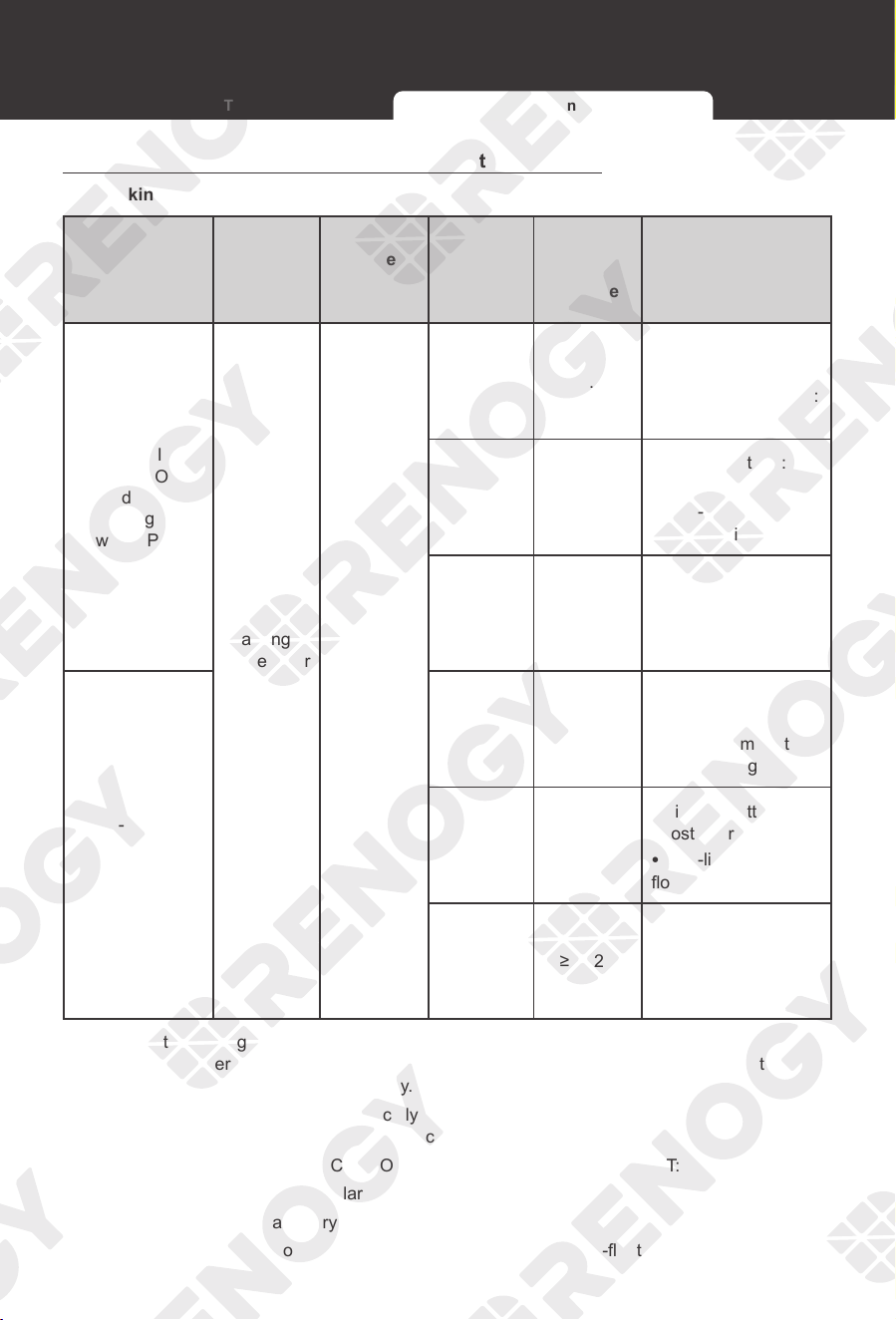
38
Hybrid charging of the solar panel and the starter battery
▇
Working conditions
Model
Working
Condition
Starter
Battery
Solar
Panel
Output
Current
Auxiliary
Battery
Voltage
Auxiliary Battery
Charging
Renogy 12V
30A Dual Input
DC-DC On-
Board Battery
Charger
with MPPT
(RBC30D1S)
Hybrid
charging
of the solar
panel and
the starter
battery
Smart:
>12V
Traditional:
>13.2V
<15A ≥13.2V
•
Lithium battery:
boost charging
•
Non-lithium battery:
float charging
≥15A <13.2V
•
Lithium battery:
boost charging
•
Non-lithium battery:
float charging
≥15A ≥13.2V
•
Lithium battery:
Non-boost charging
•
Non-lithium battery:
Non-float charging
Renogy 12V
50A Dual Input
DC-DC On-
Board Battery
Charger
with MPPT
(RBC50D1S)
<25A ≥13.2V
•
Lithium battery:
boost charging
•
Non-lithium battery:
float charging
≥25A <13.2V
•
Lithium battery:
boost charging
•
Non-lithium battery:
float charging
≥25A ≥13.2V
•
Lithium battery:
Non-boost charging
•
Non-lithium battery:
Non-float charging
When the battery charger determines automatically that the power supply of the solar panel is
insufficient, the battery charger will adjust automatically to allow both the solar panel and the
starter battery to charge the auxiliary battery.
The battery charger determines automatically that the power supply of the solar panel is
insufficient if one of the following conditions occurs:
1. Renogy 12V 30A Dual Input DC-DC On-Board Battery Charger with MPPT:
(1) The output current of the solar panel is less than 15A.
(2) The voltage of the auxiliary battery is less than 13.2V.
(3) The state of charge of the auxiliary battery is non-boost / non-float.
To Solar Panel To Starter Battery To Both Solar Panel and Starter Battery
Working Logic Working Logic
39
2. Renogy 12V 50A Dual Input DC-DC On-Board Battery Charger with MPPT:
(1) The output current of the solar panel is less than 25A.
(2) The voltage of the auxiliary battery is less than 13.2V.
(3) The state of charge of the auxiliary battery is non-boost / non-float.
NOT
E
z
If the output voltage of the starter battery fails to meet the working conditions of the battery
charger, the battery charger cannot switch to the hybrid charging mode, so that it adjusts
automatically to use only the solar panel to charge the auxiliary battery.
z
The starter battery fails to meet the working conditions of the battery charger if one of the
following conditions occurs:
(1) For smart alternator: The voltage of the starter battery is less than 11.5V.
(2) For traditional alternator: The voltage of the starter battery is less than 12.7V.
z
In the hybrid charging mode, if the solar panel meets the working conditions, the battery
charger adjusts automatically to use the solar panel only to charge the auxiliary battery.
z
If neither the solar panel nor the starter battery meets the working conditions, the battery
charger stops operating.
▇
Charging Logic
When both the solar panel and the starter battery charge the auxiliary battery at the same time,
each can provide a charging current of at most half of the rated current to charge the auxiliary
battery at the same time.
Model Charging Current
Renogy 12V 30A Dual Input DC-DC On-Board
Battery Charger with MPPT (RBC30D1S)
≤15
A (from the solar panel)
≤15
A (from the starter battery)
Renogy 12V 50A Dual Input DC-DC On-Board
Battery Charger with MPPT (RBC50D1S)
≤
25A (from the solar panel)
≤25
A (from the starter battery)
Renogy 12V 30A Dual Input DC-DC On-Board Battery Charger with MPPT provides the maximum
charging current of 15A from the solar panel, and the maximum charging current of 15A from the
starter battery to charge the auxiliary battery.
Renogy 12V 50A Dual Input DC-DC On-Board Battery Charger with MPPT provides the maximum
charging current of 25A from the solar panel, and the maximum charging current of 25A from the
starter battery to charge the auxiliary battery.
NOT
E
z
In the process of hybrid charging, if the starter battery voltage drops to a standard value
which is below the working conditions of the battery charger, the battery charger will adjust
automatically to use the solar panel to charge the auxiliary battery alone.
z
When the auxiliary battery is fully charged, the battery charger adjusts automatically to use the
solar panel to charge the starter battery. If both the auxiliary battery and the starter battery are
fully charged, the battery charger activates the standby state.
z
The battery charger recognizes automatically that the auxiliary battery is fully charged if:
To Solar Panel To Starter Battery To Both Solar Panel and Starter Battery

Working Logic
40
To Solar Panel To Starter Battery To Both Solar Panel and Starter Battery
(1) The non-lithium battery enters float charging.
(2) The lithium battery maintains boost charging for 1 hour.
▇
Over-voltage protection
Renogy 12V 30A Dual Input DC-DC On-Board Battery Charger with MPPT: When the output
voltage of the solar panel is greater than 30.5V, the battery charger will trigger the overvoltage
protection and stop operating immediately, and will not operate until the output voltage of the solar
panel is less than 29.5V.
Renogy 12V 50A Dual Input DC-DC On-Board Battery Charger with MPPT: When the output
voltage of the solar panel is greater than 50.5V, the battery charger will trigger the overvoltage
protection and stop operating immediately, and will not operate until the output voltage of the solar
panel is less than 49.5V.
When the voltage of the starter battery is greater than 16.5V, the battery charger triggers over-
voltage protection and stops operating immediately. The battery charger will not operate until the
voltage of the battery is less than 15.5V.
Low current cut-off mode
▇
Working conditions
When the output current of the solar panel is less than 7A, the battery charger will automatically
enter the low current cut-off mode and switch to charging only with the alternator.
Scan the QR code at the end of the manual to download the DC Home app. Through the app,
you can set the low-current cut-off mode. You can also change the range of the low-current cut-
off value of the solar panel. It is recommended to set it to 7-10A. If the value is set to 0A, the low
current cut-off mode will be turned off.
After the low current cut-off mode is set and activated, when the output current of the solar panel
is less than the set value, the battery charger activates the battery charging mode only.
▇
Exit conditions
After the battery charging mode activates for 5 minutes, the battery charger judges the charging
current of the solar panel again.
If the low current cut-off value < charging current ≤ half of the rated current lasts for 10s
continuously, the battery charger will return to the simultaneous charging mode of both the solar
panel and the starter battery.
If the charging current is greater than or equal to half of the rated current and the auxiliary battery
is set in the float or boost stage, the battery charger will return to the independent charging mode
of the solar panel.
Working Logic LED Indicators
41
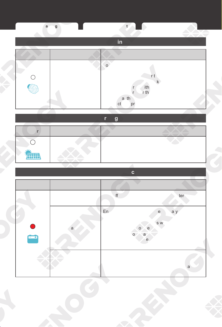
Alternator / Charging Indicator
Color Status Description
Red
ON The alternator is charging the auxiliary battery.
Slow Flashing
The Positive Solar Terminal is charging the starter
battery.
OFF Not charging
Solar Charging Indicator
Color Status Description
Red
ON Bulk charge (MPPT)
Slow Flashing Boost charge
Single Flashing Float charge
Fast Flashing Equalization charging
Double Flashing Current-limit Charging
OFF Not charging
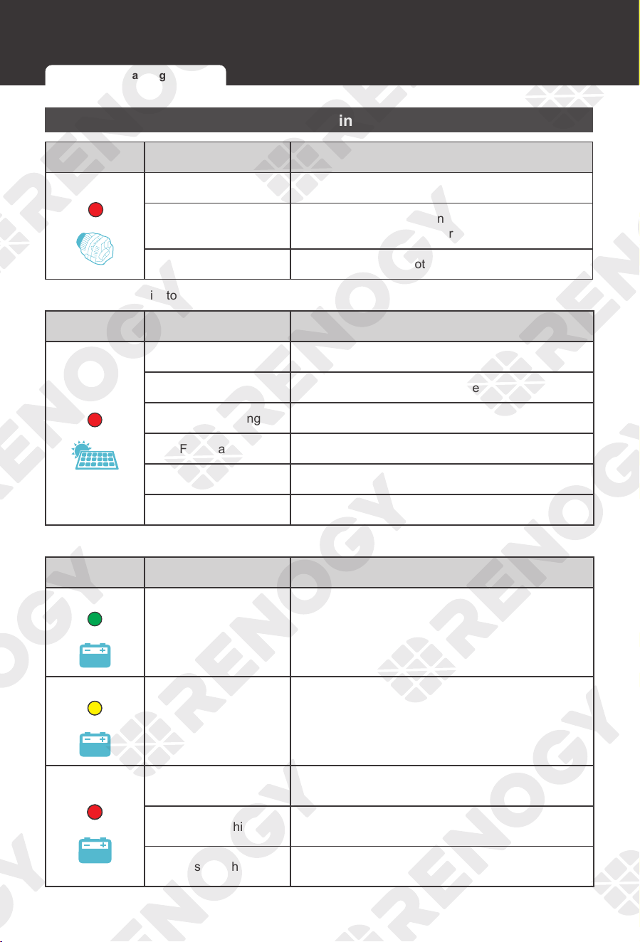
Auxiliary Battery Indicator
Color Status Description
Green
ON Full
Yellow
ON Normal voltage
Red
ON Undervoltage
Slow Flashing Overdischarge
Fast Flashing Overvoltage / Overtemperature
LED Indicators
Alternator / Charging Indicator Battery Type Indicator
LED Indicators
42
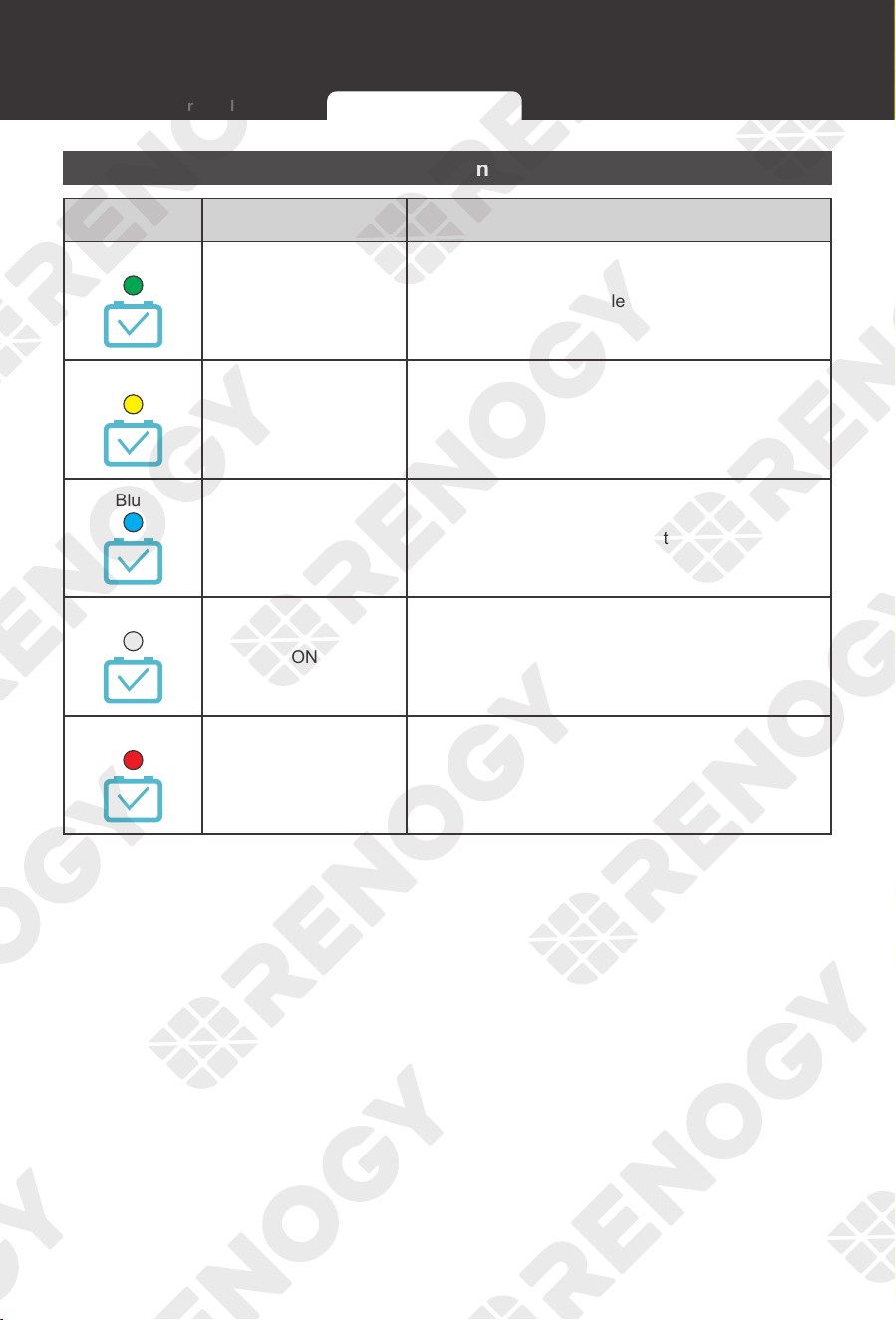
Battery Type Indicator
Color Status Description
Green
ON SLA (Default) - Sealed Lead Acid Battery
Yellow
ON Gel - Gel Battery
Blue
ON Li - Lithium Battery
White
ON User - User-defined Battery
Red
ON FLD - Flooded Battery
Alternator / Charging Indicator Battery Type Indicator
LED Indicators Troubleshooting
43
Troubleshooting
Alternator / Charging Indicator
Color Status Description
OFF
For a traditional alternator, check the alternator
input voltage. Measure it with a multimeter. Ensure
that the voltage is greater than or equal to 13.2V.
For a smart alternator, check the alternator input
voltage. Measure it with a multimeter. Ensure that
the voltage is greater than or equal to 12V.
Ensure that the IGN Signal Wire, cables, and fuses
are intact and properly connected.
Solar Charging Indicator
Color Status Description
OFF
Ensure that the solar panel is not being shaded (by
a tree etc.). Ensure the voltage of the solar panel is
higher than 15V with a multi-meter and check the
electric connections.
Auxiliary Battery Indicator
Color Status Description
Solid Red
Turn off any loads connected to the battery and
recharge the auxiliary battery.
Fast Flashing Red
Ensure that the voltage of the auxiliary battery is
12V.
Ensure the installation site is well ventilated. Avoid
additional heating of the battery.
Disconnect all loads and chargers from the battery
and allow the battery temperature to decrease to
operational specifications.
Slow Flashing Red
Ensure that cables and fuses are intact and
properly connected.
Turn off any loads connected to the battery and
recharge the auxiliary battery.
Alternator / Charging Indicator Solar Charging Indicator Auxiliary Battery Indicator
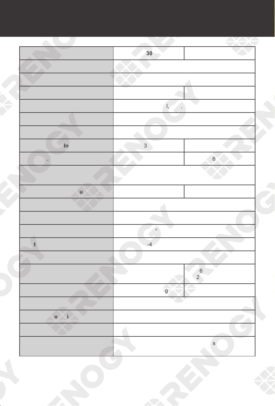
Technical Specifications
44
Product RBC30D1S RBC50D1S
System Voltage 12V DC
Battery Voltage Range 9V to 16V DC
Maximum Charging Current 30A 50A
Battery Type SLA, Gel, FLD, Li, User-defined
Auxiliary Battery Charging Mode MPPT
Charging Efficiency Up to 97%
Max. Solar Input Voltage 30V 50V
Max. Solar Input Power 400W 660W
Alternator Input Voltage
Traditional Alternator: 13.2V to 16V DC
Smart Alternator (Euro 6): 12V to 16V DC
Max. Alternator Input Power 400W 660W
Temp. Compensation Coefficient -3mV /
°
C / 2V
Self-consumption < 30mA
Operating Temperature Range -31
°
F to 149
°
F / -35
°
C to 65
°
C
Storage Temperature Range -40
°
F to 176
°
F / -40
°
C to 80
°
C
Humidity Range 0% to 95% (NC)
Dimensions
9.61 x 5.75 x 3.03 in
244 x 146 x 77 mm
9.61 x 5.75 x 3.78 in
244 x 146 x 96 mm
Weight 3.11 lb / 1.41 kg 4.10 lb / 1.86 kg
Terminal Size M8x1.25-14 mm
Communication Protocol RS485
Grounding Common Negative
Certifications
CE; ROHS; FCC Part 15 Class B;
ETL listed to UL1741 & CSA C22.2
Technical Specifications
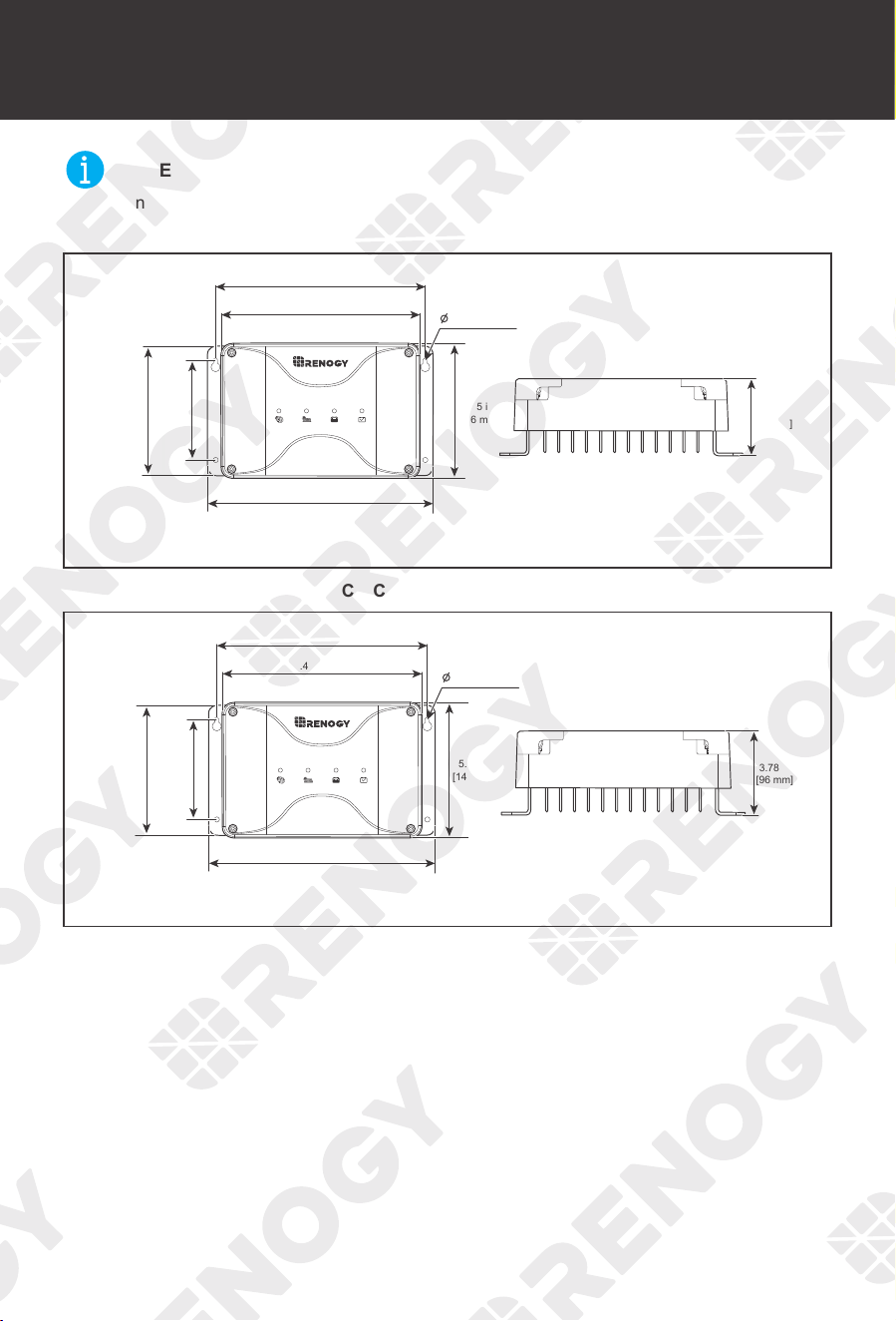
Technical Specifications Dimensions
45
Dimensions
NOT
E
z
Dimension tolerance: ±0.2 in (0.5 mm)
▇
Renogy 12V 30A Dual Input DC-DC On-Board Battery Charger with MPPT (RBC30D1S)
8.94 in [227 mm]
9.61 in [244 mm]
5.75 in
[146 mm]
3.03 in
[77 mm
]
5.51 in
[140 mm]
4.25 in
[108 mm]
8.46 in [215 mm]
0.18 in [4.5 mm]
▇
Renogy 12V 50A Dual Input DC-DC On-Board Battery Charger with MPPT (RBC50D1S)
8.94 in [227 mm]
8.46 in [215 mm]
5.51 in
[140 mm]
4.25 in
[108 mm]
9.61 in [244 mm]
5.75 in
[146 mm]
3.78 in
[96 mm
]
0.18 in [4.5 mm]
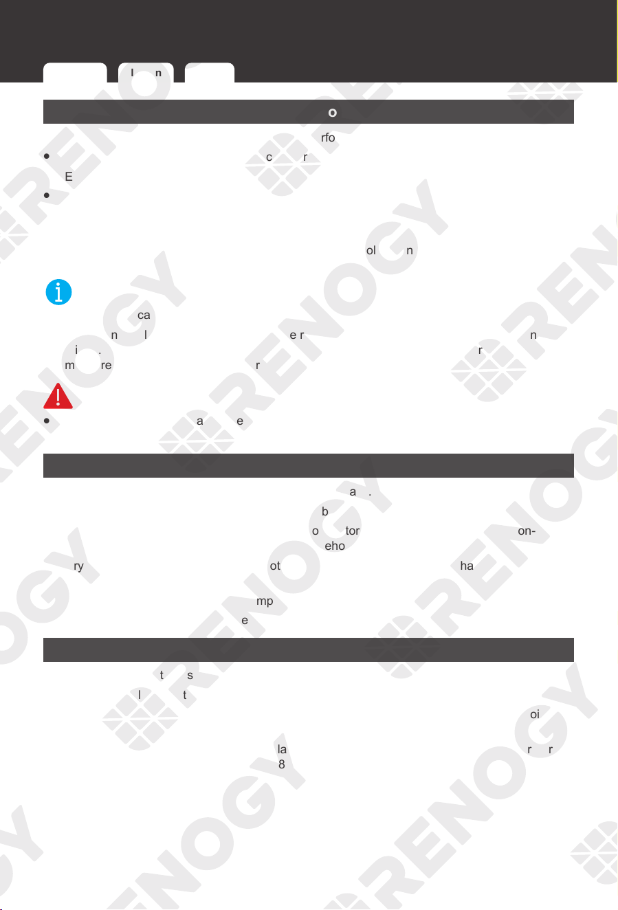
Maintenance
46
Maintenance
Inspection
For optimum performance, it is recommended to perform these tasks regularly.
z
Check the appearance of the battery charger to make sure it is clean and dry.
z
Ensure the battery charger is installed in a clean, dry and ventilated area.
z
Ensure the firmness of all cables and check if there are any loose, damaged or burnt
connections.
z
Make sure that all indicators are in normal state.
z
Ensure there is no corrosion, insulation damage, or discoloration marks of overheating or
burning.
NOT
E
z
In some applications, corrosion may exist around the contacts.
Corrosion can loosen springs and increase resistance, leading to premature connection
failure. Apply dielectric grease to each connector contact periodically. Dielectric grease repels
moisture and protects the connector contacts from corrosion.
WARNIN
G
z
Risk of electric shock! Make sure that all power is turned off before touching the terminals on
the battery charger.
Cleaning
Follow the steps below to clean the battery charger regularly.
z
Disconnect all cables that are connected to the battery charger.
z
Wipe the housing of the battery charger and connector contacts with a dry cloth or non-
metallic brush. If it is still dirty, you can use household cleaners.
z
Dry the battery charger with a clean cloth and keep the area around the charger clean and
dry.
z
Make sure the battery charger is completely dry before reconnection.
z
When reconnecting, follow the steps in the user manual.
Storage
Follow the tips below to ensure that the battery charger is stored well.
z
Disconnect all cables that are connected to the battery charger.
z
By applying dielectric grease to each connector contact, the dielectric grease repels moisture
and protects the connector contacts from corrosion.
z
Store the battery charger in a well-ventilated, dry and clean environment with a temperature
between -40° F and 176° F or -40° C to 80° C.
Inspection Cleaning Storage
Maintenance Emergency Responses
47
Emergency Responses
In the event of any threat to health or safety, always begin with the steps below before addressing
other suggestions.
z
Immediately contact the fire department or other relevant emergency response team.
z
Notify all people who might be affected and ensure that they can evacuate the area.
WARNING
z
ONLY perform the suggested actions below if it is safe to do so.
Fire
1. Disconnect all cables connected to the battery charger.
2. Put out the fire with a fire extinguisher. Acceptable fire extinguishers include water, CO
2
, and
ABC.
WARNIN
G
z
Do not use type D (flammable metal) fire extinguishers.
Flooding
1. If the battery charger is submerged in water, stay away from the water.
2. Disconnect all cables connected to the battery charger.
Smell
1. Disconnect all cables connected to the battery charger.
2. Make sure nothing is in contact with the battery charger.
3. Ventilate the room.
Noise
1. Disconnect all cables connected to the battery charger.
2. Make sure no foreign objects are stuck in the battery charger ports.
Fire Flooding Smell Noise
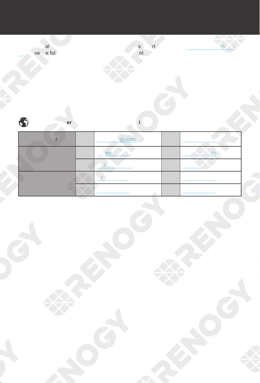
Technical Support
48
Technical Support
For additional support, contact the Renogy technical support team through renogy.com/contact-
us/. Have the following information available when contacting Renogy.
z
Owner name
z
Contact information
z
Order number
z
Purchase channel
z
Serial number
z
Brief description of the issue
Renogy offers premium services worldwide:
North America US www.renogy.com CN www.renogy.cn
Asia / Pacific
UK
uk.renogy.com CA ca.renogy.com
AU
au.renogy.com JP renogy.jp
Europe
FR
fr.renogy.com DE de.renogy.com
ES
es.renogy.com KR kr.renogy.com

Technical Support Technical Support
49
FCC Statement
This device complies with Part 15 of the FCC Rules. Operation is subject to the following two
conditions:
(1) This device may not cause harmful interference;
(2) This device must accept any interference received, including interference that may cause
undesired operation.
This equipment has been tested and found to comply with the limits for a Class B digital device,
pursuant to Part 15 of the FCC Rules. These limits are designed to provide reasonable protection
against harmful interference in a residential installation. This equipment generates uses and can
radiate radio frequency energy and, if not installed and used in accordance with the instructions,
may cause harmful interference to radio communications. However, there is no guarantee
that interference will not occur in a particular installation. If this equipment does cause harmful
interference to radio or television reception, which can be determined by turning the equipment off
and on, the user is encouraged to try to correct the interference by one or more of the following
measures:
(1) Orient or relocate the receiving antenna.
(2) Increase the separation between the equipment and receiver.
(3) Connect the equipment into an outlet on a circuit different from that to which the receiver is
connected.
(4) Consult the dealer or an experienced radio / TV technician for help.
FCC Radiation Exposure Statement
This equipment complies with FCC radiation exposure limits set forth for an uncontrolled
environment. This equipment should be installed and operated with minimum distance 20 cm
between the radiator & your body.
Renogy Empowered
Renogy aims to empower people around the world through distribution of DIY-friendly renewable
energy solutions.
We intend to be a driving force for sustainable living and energy independence.
In support of this eort, our range of solar products makes it possible for you to minimize your
carbon footprint by reducing the need for grid power.
Live Sustainably with Renogy
Did you know? In a given month, a 1KW solar energy system will...
Save 170 pounds of coal from being burned
Save 300 pounds of CO
2
from being released into the atmosphere
Save 105 gallons of water from being consumed
PLUS
Renogy Power
Renogy Power Plus allows you to stay in the loop with upcoming solar energy innovations, share
your experiences with your solar energy journey, and connect with like-minded people who are
changing the world in the Renogy Power Plus community.
Also, follow us on Youtube @Renogy Solar, Facebook @Renogy, and Instagram @renogyocial.
Renogy reserves the right to change the contents of this manual without notice.
Visit renogy.com to find relevant documentation or get more support via "Contact Us".
Join the Renogy Power Plus Community
by downloading the DC Home app.
Find your e-warranty here, and more.
RENOGY.COM
Manufacturer: RENOGY New Energy Co.,Ltd
Address: No.66, East Ningbo Road Room 624-625
Taicang German Overseas Students Pioneer Park
JiangSu 215000 CN
Manufacturer: RENOGY New Energy Co.,Ltd
Address: No.66, East Ningbo Road Room 624-625
Taicang German Overseas Students Pioneer Park
JiangSu 215000 CN
EVATOST CONSULTING LTD
Centre, Taffs Well, Cardiff, Wales, CF15 7QR
Suite 11, First Floor, Moy Road Business
eVatmaster Consulting GmbH
60325 Frankfurt am Main, Germany
contact@ evatmaster. com
Battinastr.30
UK REP
EC REP