Loading ...
Loading ...
Loading ...
Water connection
Models designed for use in conjunction with a low pressure
hot water supply should be individually connected (in a parallel
circuit) to the fl ow and return pipe-work. Connections (see ‘a’ in
Fig. 3) are: ½” BSPT (CAB series) and isolation valves (see ‘b’
in Fig. 3) should be fi tted as close to the air curtain connection
points as possible. For commissioning, air bleed valves (see ‘c’
in Fig. 3) are fi tted to the coil, which can be accessed by removal
of the ceiling tile - see Fig. 2.
Maximum water supply conditions are 125ºC and 8 bar
(0.8MPa).
To aid installation, the water coil connections may be moved to
either side of the appliance. By removing the water coil and
appropriate knockouts the water coil can then be re-inserted into
the required orientation. This procedure should be carried out
before mounting the appliance.
Switch Panel Installation
The backing box (standard double gang) should be surface
mounted onto a suitable wall, alternatively a recessed box
can be used (not supplied). Suitable conduit should be used
where applicable to carry the cable between the heater and the
switch. A CAT5 computer network cable with straight through
connections should be used to connect the switch panel to the
appliance PCB.
Warning: Ensure cable is secure and the cable path does not
come into contact with heater element or other moving parts.
Note: If using a door switch, an additional 2 core (low voltage)
cable is required between the door switch and the air curtains.
Test all switch settings once installation is complete.
Electrically heated variants
Operation using switch box - CABC5
Switch on electrical supply to the air curtain. Rotate the switch to
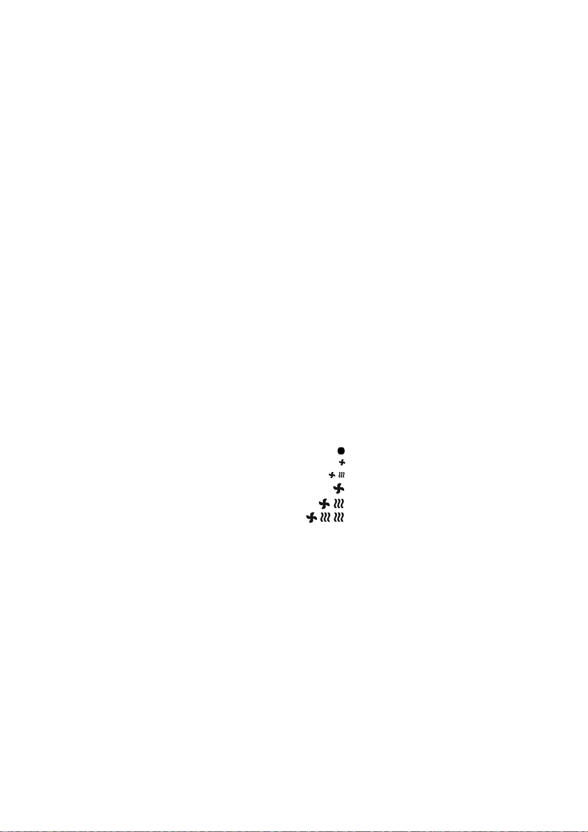
the desired heat setting. Settings available are;
OFF
Low Fan
Low Fan with Low Heat
High Fan
High Fan with Low Heat
High Fan with Full Heat
The rocker (auto / manual) switch allows for manual over-ride of
a door switch if fi tted. Manual allows the appliance to run at the
desired setting, while Auto provides an energy saving feature by
shutting down the appliance while the door is closed.
The unit should always be switched OFF using the switch
box control, and not by mains power supply interruption.
When the unit is switched off (via the switch box) the fan will run
on for 1 minute without heat to discharge any residual energy
from the heating elements.
When fi rst turned on the control will run through a system check.
The selected settings will be reached and maintained after a 30
second period.
Electrical
The installation of this appliance should be carried out by a
competent electrician and be in accordance with the current IEE
wiring regulations.
Fixing Positions
This appliance must be mounted to a suitable ceiling - see Fig.
1 for fi xing dimensions and Fig. 5, 6, or 7 for mounting positions
and ‘Mounting’ sections below for fi xing details. This appliance
should not be mounted less than 1.8m from the fl oor.
Mounting into a Standard Ceiling Void
1. Side Fixings - Using a suitable ceiling surface, mark off and
drill for M8 drops rods. Dimensions can be found on Fig.1. Cut
the M8 drop rods to the desired length, taking note of the fi nal
position of the appliance relative to the distance to the mounting
surface. Mount the drop rods to the ceiling surface. Remove the
ceiling tiles on the appliance. (see Fig. 2) Using suitable lifting
equipment raise up the appliance to the drop rods as shown
in Fig. 7a & 7b. Connect the appliance to the drop rods using
standard M8 lock nuts and washers.
2. Top Mounted Inserts - If a suitable (unistrut) structure is
available, mark off and drill for M8 threaded bolts. Insert the bolts
down through the structure. Dimensions can be found on Fig.
1. Using suitable lifting equipment raise up the appliance to the
bolts. Screw the bolts into the threaded inserts on the top of the
appliance, and tighten securely.
Electrical connection
All products are fi tted with a microprocessor control. Electrical
power and control connections are made as shown in Fig. 4. A
suitable local isolating switch must be provided in the electrical
supply circuit with at least 3mm clearance on each pole. In order
to access the electrical connections, remove the outlet grilles (‘x’
in Fig. 2) by undoing the four fasteners in each tile. For the Water
heated and Ambient models only, the pressure plate must also be
removed.
All Electric Models - Having removed a ‘knock out’ in the
top panel, feed an appropriate supply cable (see ‘a’ in Fig. 4A)
through a suitable cable gland (not supplied) fi tted in the top
panel and attach to the terminal block (see ‘b’ in Fig. 4A).
All Water heated and Ambient Models - Having
removed a ‘knock out’ in the top panel, feed an appropriate
supply cable (see ‘a’ in Fig.4B) through a suitable cable gland
(not supplied) fi tted in the top panel and attach to the PCB (see
‘b’ in Fig. 4B).
All Models - A suitable cable (CAT5 or equivalent) for a switch
panel (kit ref. - CABC5 for electrically heated models or CABC6
for water heated/ambient models) can be similarly introduced
through the top panel and plugged into the circuit board as
shown in Fig. 4A & 4B. If the unit is to be operated in conjunction
with a door switch, a normally open switch should be wired as
per ‘D’ in Fig. 8 & 9 as appropriate.
Note: If using a door switch, an additional 2 core (low voltage)
cable is required between the door switch and the air curtains.
If the unit is to be connected to a Building Energy Management
System, connections are made as per ‘S0, S1, & S2’ in Fig. 8 &
9 as appropriate.
Loading ...
Loading ...