V-ZUG Ltd
V-ZUG Ltd, Industriestrasse 66, CH-6301 Zug
[email protected], www.vzug.com
Planning aid
International collection
Kitchen appliances
J001059-R20
24.05.17
5
1
Overview of connections, ranges and dimensions
Electrical connections must be carried out by qualified experts in accordance with the guidelines and standards for low-
voltage installations and the specifications of the local electricity supply companies.
A plug-in appliance may only be connected to a socket outlet with earthing contact, installed according to specifications. An
all-pole mains isolating device with 3 mm contact opening should be provided in the house wiring system. Switches, plug
and socket devices, circuit breakers and fusible cut-outs which are accessible after installation and which have all-poles
switching are permissible as isolating devices. Effective earthing and separately installed neutral and earth conductors en-
sure safe and fault-free operation. After installation, live parts and cables with basic insulation must not be accessible.
Check old installations.
Electrical connections must be carried out by qualified experts.
Plan a separate inlet for the electrical connection for each appliance.
1.1
General operating conditions
Detailed information on the electrical connection data can be found at the beginning of each section.
Value Nominal value Minimum Maximum
Voltage 230 V 207 V 253 V
Voltage 400 V 360 V 440 V
Frequency 50 Hz sinusoidal 49 Hz sinusoidal 51 Hz sinusoidal
• Short duration frequency variation in the mains: ± 5 %
• Long duration frequency stability in the mains (for synchronous clocks): ± 10 ppm
• The appliances are designed for use up to a max. altitude of 2000 m above sea level.
1.2
Using residual current devices in house wiring system / fault current
High fault currents are inherently present in ovens and hobs. The values can be affected by various factors and vary widely. Fault
currents of up to approximately10mA per appliance are permissible in accordance with the norm. The values are measured in the
warm operating state.
If residual current devices (RCDs) are used in the house wiring system, we recommend that the above-mentioned appliances have
their own RCD protection, separate from the power supply for the rest of the system. 30mA or higher should be selected as the trip-
ping current for the residual current device.
V-ZUG Ltd
V-ZUG Ltd, Industriestrasse 66, CH-6301 Zug
[email protected], www.vzug.com
Planning aid
International collection
Kitchen appliances
J001059-R20
24.05.17
8
1.4
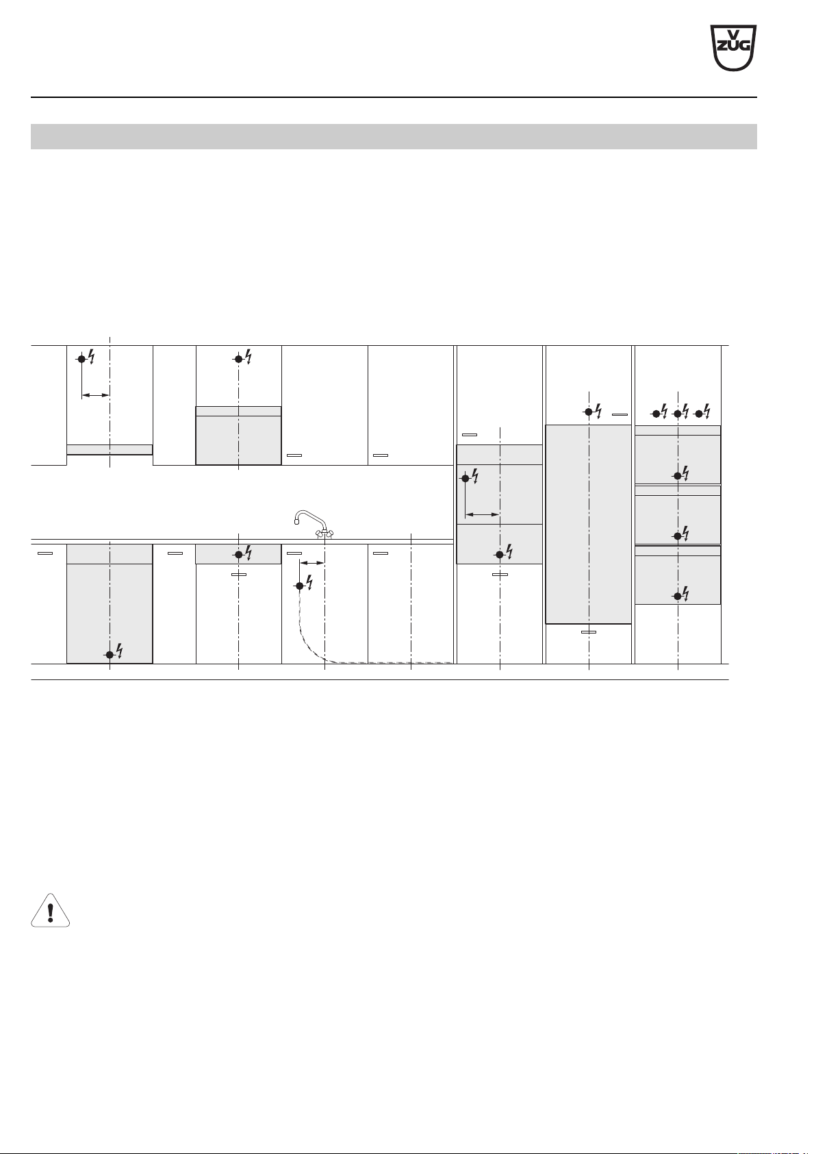
Positions of electrical connections
For EURO kitchens, allowance from the floor can vary. In this case, the electrical connection should be calculated using the dimen-
sion from the bottom edge of the appliance.
Oven above an oven
With this combination, an electrical connection should be provided for each appliance. Depending on the installation height and the
type of combination, the connections may be located at different heights.
Wall hoods with telescopic casing
The electrical connection must pass between the exhaust air piping and the lagging sheets. The measurements given in the table en-
sure that this condition is met.
M3
7
M1
M2
6
1
3
4
5
2
8
1 Wide switch box / control box / autarchic hob
2 Refrigerator in base unit / dishwasher
3 Oven/coffee-center
4 Combinations (oven / steam cooker / microwave)
5 Refrigerator, winecooler in tall unit
6 Microwave in a wall unit
7 Range hood
8 Warming drawer
M1 Distance from centre to dishwasher/refrigerator connection in base unit
M2 Distance from centre to coffee-center connection
M3 Distance from centre to range hood connection
Provide additional clearance for electrical connections if the installation niche has only the minimum depth.
V-ZUG Ltd
V-ZUG Ltd, Industriestrasse 66, CH-6301 Zug
[email protected], www.vzug.com
Planning aid
International collection
Kitchen appliances
J001059-R20
24.05.17
52
9
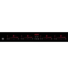
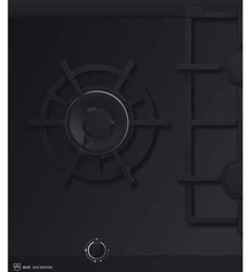
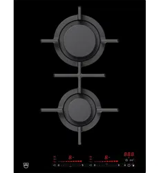
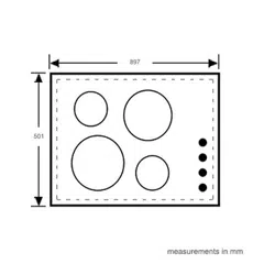
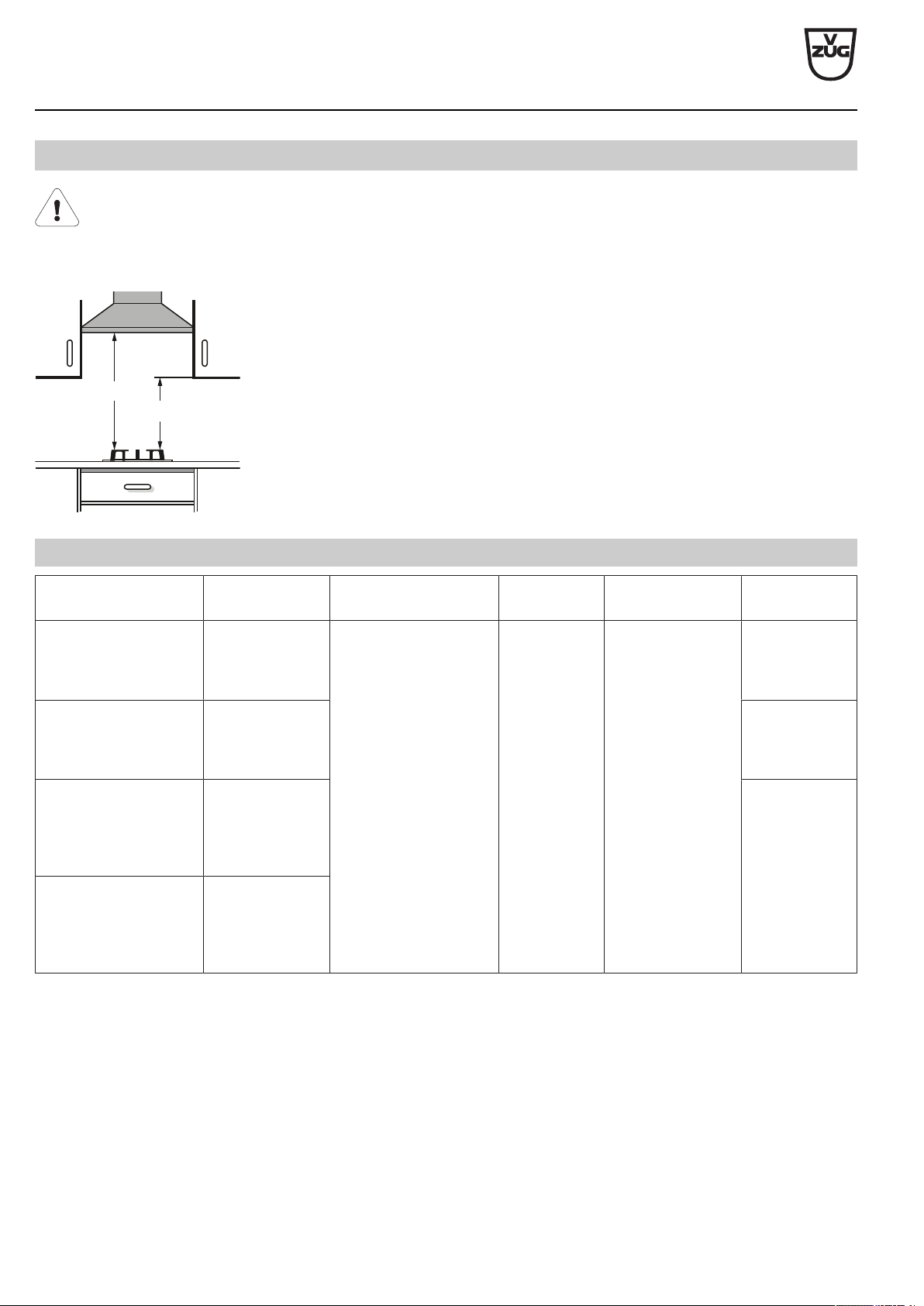
Gas hobs
The distance from the appliance cut-out to the back wall must be ≥50mm and to the side walls ≥200mm. Parts such as
side walls and reinforcing strips which protrude into the installation space under the cooking zone must be made of fire-res-
istant material.
The distance between the underside of the appliance tray and any part of the cabinet beneath that is made of combustible
material must be ≥ 20mm.
≥750
≥450
When a range hood is installed above the gas hob, the minimum distance given for
the particular range hood must be observed.
Furthermore, the minimum distances illustrated must be strictly complied with even if
a lower value is stated for the range hood.
A gas hob cannot be built in directly over another appliance due to the installation
depth and the gas connection.
9.1
Electrical connection data
Appliance Country group * Mains connection Fuse Rated load Mains cable
GAS411GSBZ,
GAS421GSBZ,
GAS641GSBZ,
GAS951GSBZ
D 220–240V~50/60Hz ≥3A <20 W 1.7m,
with plug
GAS411GSAZ,
GAS421GSAZ,
GAS641EKAZ/GSAZ,
GAS951GSAZ
A, B, E 1.7 m,
without plug
GAS311EKBZ/GKBZ,
GAS411GSBZ,
GAS321EKBZ/GKBZ,
GAS421GSBZ,
GAS731EKBZ/GKBZ
F 1.7m,
with plug
GAS311EKBZ/GKBZ,
GAS411GSBZ,
GAS321EKBZ/GKBZ,
GAS421GSBZ,
GAS731EKBZ/GKBZ
C
* Country group (see page 2)
V-ZUG Ltd
V-ZUG Ltd, Industriestrasse 66, CH-6301 Zug
[email protected], www.vzug.com
Planning aid
International collection
Kitchen appliances
J001059-R20
24.05.17
53
9.2
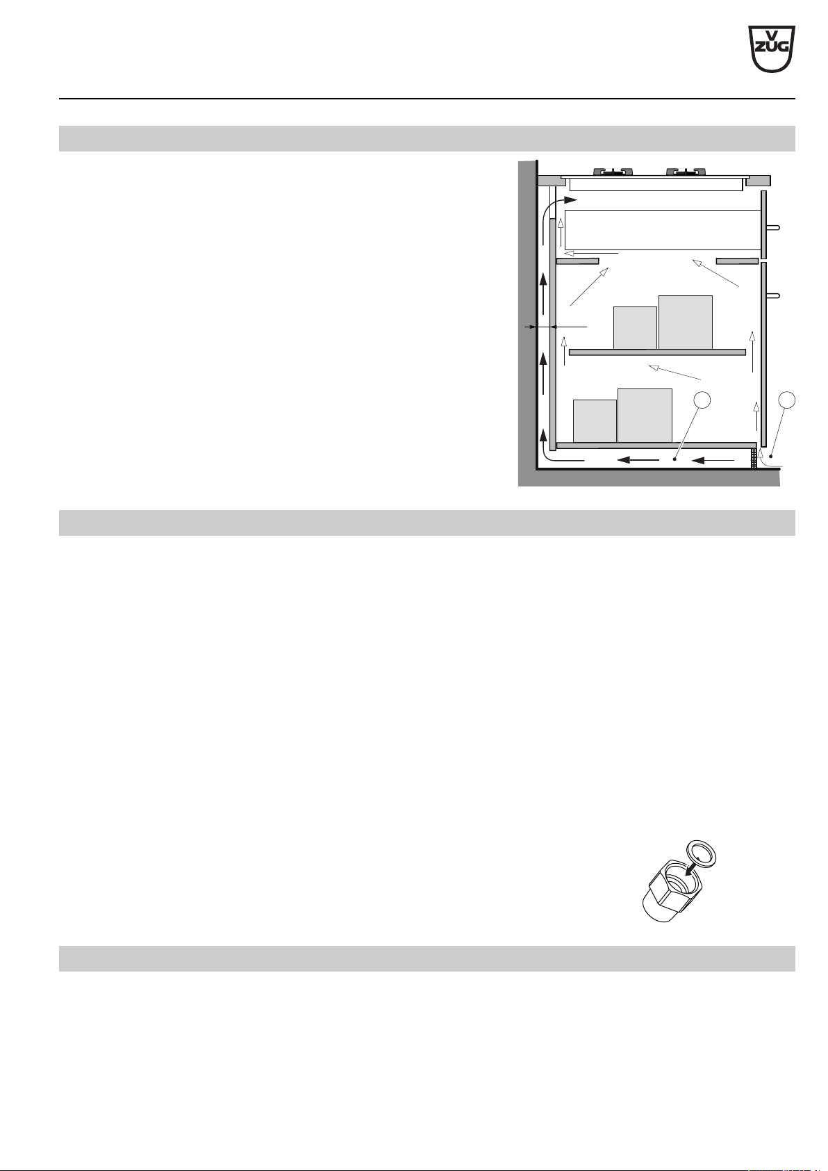
Ventilation
In order to guarantee minimum ventilation, a space of ≥20mm height is ne-
cessary beneath the appliance.
≥15
B
A
A The rear panel of the base unit must be open around the work surface
cut-out to guarantee continuous air circulation via the ventilation slits.
The air must be drawn in from outside the cabinet and be able to circu-
late freely from inside the cabinet to the hob.
B Alternatively, a concealed fresh air supply can ensure air circulation in-
side the cabinet.
So that enough cold air can be drawn in, there must be a continuous
supply of fresh air circulating till outside the cabinet.
The air must be drawn in from outside the cabinet and be able to circu-
late freely from inside the cabinet to the hob.
9.3
Gas connection
► The gas connection must be positioned so that the stop-cock and the supply connection point are accessible with the appliance in-
stalled.
► The gas connection must be positioned so that it does not get detrimentally hot during operation. In particular, the gas hose as-
semblies and the appliance’s connection fittings must be clear of hot exhaust gases (e.g. from an oven).
► It must be ensured that the gas hose and the mains connection do not touch any hot parts of the appliance, otherwise the gas
hose and the mains cable could become damaged through heat.
► A flexible connection lead (max. length 1.5 m) must be positioned so that it runs freely and does not come into contact with any
movable parts of the kitchen cabinets (e.g. a drawer).
½-inch metric thread
The gas connection on the appliance has a ½-inch external thread in accordance with ISO 228/1. If the gas installation on site
already has a corresponding counterpart, the gas appliance can be directly connected to it.
Thread length
½-inch conical thread
If the installation on site has a conical thread, the transition piece and sealing ring must first be
screwed onto the appliance. The transition piece has a conical external thread R ½-inch in accord-
ance with ISO 7/11. In the case of a conical screw connection, the thread makes the seal, which is
why the thread must be sealed with hemp or Teflon tape.
9.4
Setting up appliance to use local gas type
The appliance settings must match the local gas type and connection pressure. If the gas type and connection pressure have not
been preset, the appliance has to be converted using the nozzle set supplied or other nozzle sets available as accessories. Informa-
tion on the default gas setting as well as on the supplied and optional nozzle sets by country can be found in the catalogue. Conver-
sion to another gas type is described in detail in the relevant installation instructions.
V-ZUG Ltd
V-ZUG Ltd, Industriestrasse 66, CH-6301 Zug
[email protected], www.vzug.com
Planning aid
International collection
Kitchen appliances
J001059-R20
24.05.17
57
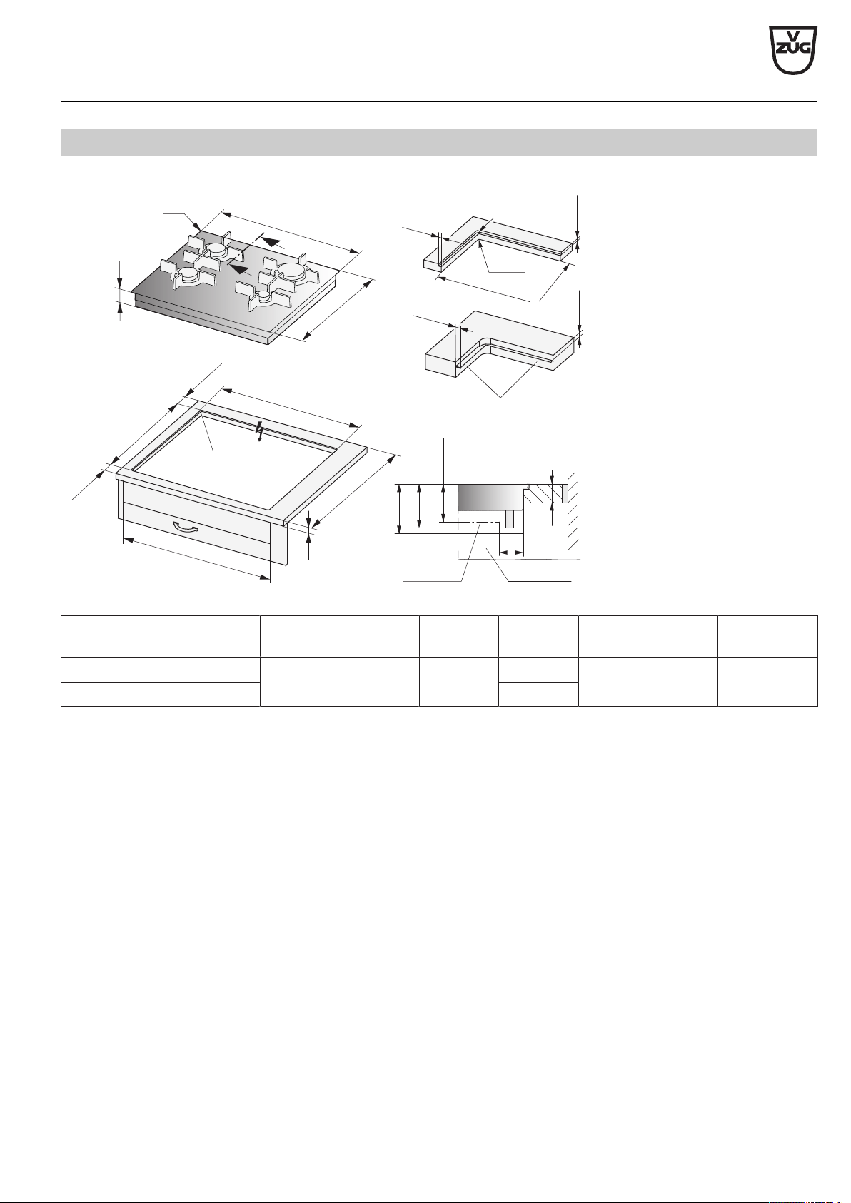
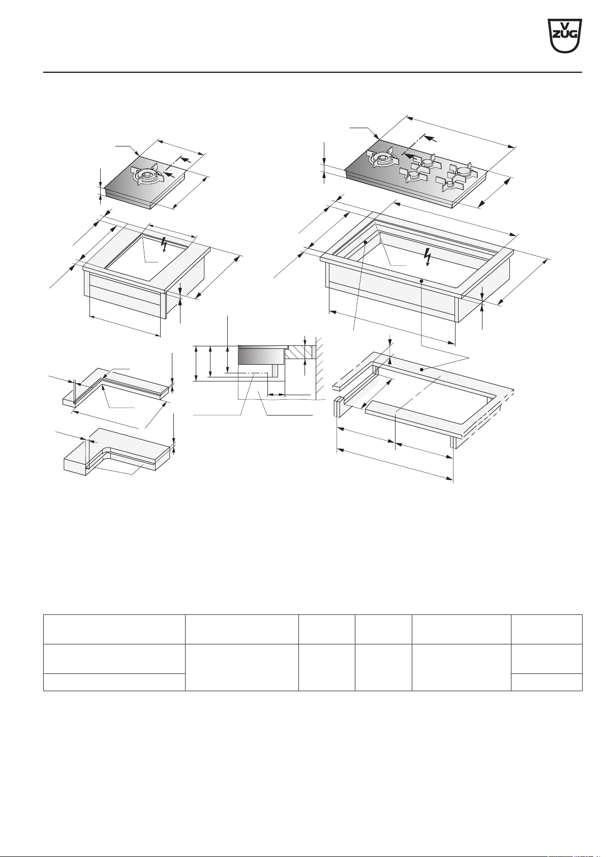
9.6
Flush installation with «DualDesign»
Ra
8
.5
0
-1
8
.5
0
-0.5
Steel angle bonded
or screw mounted
Detail Z
C
D
R0–5
H
Y – Y
B
A
Z
600
577±1
507±1
≥41.5
≥41.5
A
600
Ri
H
501
Y
Y
571
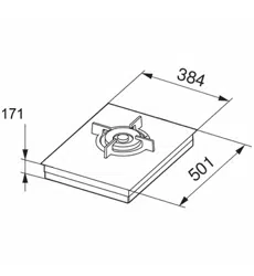
GAS641EKAZ (31054), GAS641GSAZ/GSBZ (31071)
S* ≥85
T ≥90
Drawer/
cabinet
Side panel
8.5
+1
0
8.5
+1
0
*The required clearance must be observed!
Type A Depends on producer B H Corner radius Ra/Ri C/D
GAS641EKAZ ≥30mm ≥175mm 88mm 5/1.5mm 560/490 mm
GAS641GSAZ/GSBZ 98mm
A Worktop depth B Required clearance for service replacement
H Dimension from the top of the work surface to the underside of the gas connection
Ri Corner radii of appliance Ra Outer corner radii of cut-out
S Minimum distance between the top of the work surface and any drawer
T Minimum distance between the cut-out in the back and any drawer
V-ZUG Ltd
V-ZUG Ltd, Industriestrasse 66, CH-6301 Zug
[email protected], www.vzug.com
Planning aid
International collection
Kitchen appliances
J001059-R20
24.05.17
58
A
507±1
≥41
.5
≥
41.5
600
Z
6
97±1
6
00
Z
H
501
281
Ri
H
Y
Y
Y
Y
H
Y – Y
B
A
S* ≥85
T ≥90
Drawer/
cabinet
Side panel
501
691
Ri
Ra
8
.5
0
-1
8
.5
0
-0.5
Steel angle bonded
or screw mounted
Detail Z
C
D
R0–5
8.5
+1
0
8.5
+1
0
≥41.5
≥41.5
507±1
600
287±1
A
275
GAS311EKBZ (31046), GAS311GKBZ (31073),
GAS321EKBZ (31050), GAS321GKBZ (31074)
GAS731EKBZ (31056),
GAS731GKBZ (31075)
*The required clearance must be observed!
Type A Depends on producer B H Corner radius Ra/Ri C/D
GAS311EKBZ/GKBZ,
GAS321EKBZ/GKBZ
≥30mm ≥175mm 88mm 5/1.5mm 270/490 mm
GAS731EKBZ/GKBZ 680/490 mm
A Worktop depth B Required clearance for service replacement
H Dimension from the top of the work surface to the underside of the gas connection
Ri Corner radii of appliance Ra Outer corner radii of cut-out
S Minimum distance between the top of the work surface and any drawer
T Minimum distance between the cut-out in the back and any drawer
V-ZUG Ltd
V-ZUG Ltd, Industriestrasse 66, CH-6301 Zug
[email protected], www.vzug.com
Planning aid
International collection
Kitchen appliances
J001059-R20
24.05.17
59
B
825
=
=
≥
500
1
2
Ra
8
.5
0
-1
8
.5
0
-0,5
Steel angle bonded
or screw mounted
Detail Z
C
D
R0–5
H
H
384
501
Y
Y
Ri
897
Ri
Y
Y
501
GAS411GSAZ/GSBZ (31063),
GAS421GSAZ/GSBZ (31064)
GAS951GSAZ/GSBZ (31072)
H
Y – Y
B
A
S* ≥85
T ≥90
Drawer/
cabinet
Side panel
8.5
+1
0
8.5
+1
0
9
00
A
60
0
903±1
507±1
≥41.5
≥41
.5
600
≥400
≥41.5
507
±1
600
A
Z
390±1
≥41.5
Z
*The required clearance must be observed!
1 Front and rear struts may be reinforced on the underside. The strut width is determined by the producer of the stone
worktop. The minimum strut width can vary according to the property of the stone.
2 For niche width 900mm, cut-outs in side walls left/right are necessary for servicing work where the appliance base
must be removed from below.
Type A Depends on producer B H Corner radius Ra/Ri C/D
GAS411GSAZ/GSBZ,
GAS421GSAZ/GSBZ
≥30mm ≥175mm 98mm 5/1.5mm 373/490mm
GAS951GSAZ/GSBZ 886/490mm
A Worktop depth B Required clearance for service replacement
H Dimension from the top of the work surface to the underside of the gas connection
Ri Corner radii of appliance Ra Outer corner radii of cut-out
S Minimum distance between the top of the work surface and any drawer
T Minimum distance between the cut-out in the back and any drawer