Loading ...
Loading ...
Loading ...
4
Connectors
You have several options when choosing connectors for your
speaker wires, and it’s really a matter of personal preference.
Three of the more commonly used are banana plugs, spade
lugs and bare wire. If you know where you want to locate your
speakers and plan to set up your system and leave them there,
then bare wire will work fine. Just make sure there are not
stray strands of wire that could come into contact. If you like
to experiment with dierent speaker locations, spade lugs or
banana plugs oer more convenient options when it comes to
disconnecting and reconnecting wires.
Basic Floor-Standing, Center, Bookshelf, and Height Module
Speaker Hookup
Make sure that the red (+) and black (-) connectors on your
amplifier or receiver connect to the red (+) and black (-) connectors
on your speakers. If your speakers sound “thin,” with little bass and
little or no center image, odds are that one of the speaker wires is
connected backwards. Double check all connections.
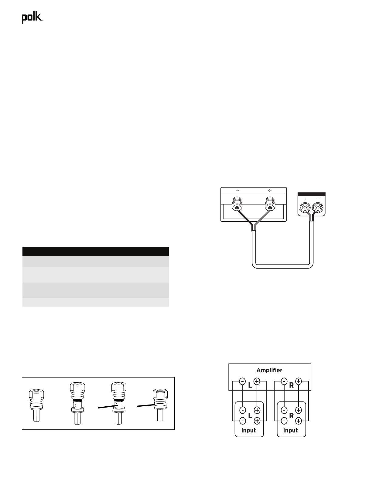
Bi-Wiring (R700 only)
Bi-wiring can provide noticeable improvements in the overall
transparency of your loudspeakers. After removing the jumpers,
run separate speaker wires to the low and high frequency
drivers from a single amplifier (the upper set of binding posts
are for the high frequency drivers, the lower set of binding
posts are for the low frequency drivers). Connect one set of
speaker wires to the upper terminals on each speaker and one
set of wires to the lower terminals. Connect the other ends of
both wire sets to the same amplifier outputs. See amplifier/AV
receiver user manual for configuration instructions (Figure 1).
What’s in the Box
Each box contains:
1. Loudspeaker(s)
2. Owner’s Manual
3. Registration Card
4. Magnetic grilles
(Speaker cable not included)
How to Connect Your System
To get the best sound quality, it’s important to wire your
speakers correctly.
Wire Preparation
Follow the hookup directions included with your receiver/
amplifier. Strip 0.5” (12.7mm) of insulation from each of the
two conductors of the wire to expose the bare metal and twist
each of the individual conductors into single un-frayed strands.
Note that one of the terminals on the rear of each speaker is
marked red (+) and the other is black (–). Make sure that you
connect the wire from the positive (+) terminal of your amplifier
or receiver to the red (+) terminal on your speaker and the wire
from the negative (–) terminal of your amplifier or receiver to
the black (–) terminal on your speaker. Most wire has some
indicator (such as color-coding, ribbing or writing) on one of
the two conductors to help you maintain consistency.
These recommendations are for all connections from the
amplifier/receiver to each speaker:
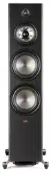
Binding Posts
To connect wire to the binding post, unscrew the binding post
cap and insert the bare wire into the hole near the base of the
binding post. Do not insert the insulated part of the wire into
the hole as this will not give you a good connection. Tighten the
binding post cap until it seats firmly with the wire, but do not
over tighten.
Runs Minimum Wire Gauge
Lengths up to 25' (5 m) 16
Lengths greater than 25' (5 m)
but less than 50' (15 m)
14
Lengths greater than 50' (15 m)
but less than 75' (25 m)
12
Lengths greater than 75' (25 m) 10
(Figure 1)
RIGHT FRONT
Loading ...
Loading ...
Loading ...