TP10KTL
TP17KTL
TP12KTL
TP20KTL
TP15KTL

Introduction
About Think Power
Thank you for using the PV grid-connected inverter of Think Power.
Established in 2011, Wuxi Xinqi Power New Energy Technology Co., Ltd. is
located in Wuxi, the Changjiang River delta plain hinterland, close to the
Changjiang River in the north and Taihu Lake in the south, whose geographical
location is superior. The registration fund of Xinqi is 20 million, specialized in
researching developing, producing, selling and providing customer service
in the PV Grid-Connected Inverter products in the type of solar
households.
For readers
This manual is applicable for technicians of inverter installation, operation and
maintenance. The readers shall be familiar with electrical knowledge.
About this manual
Please read this manual carefully before using products. This manual shall be
kept in a place which is convenient to use. Operator using this manual must be
a qualified electrical engineer certified by the local electrical authority.
Copyright
The copyright of this manual belongs to Wuxi Xinqi Power New Energy
Technology Co., Ltd. Any part or the en
tire of this manual cannot be carried in
public without a written permission.
Because of the continuous product upgrading, this manual will be updated
correspondingly, and thus there will be some unconformity between the manual
description and the products, and the user can acquire the most updated
version from www.thinkpower.com.cn
or Think Power will not be
responsible for
informing the user of the manual upgrading.
Introduction
Since its inception, our company focused on the technology, guided by
products, had a fully automatic production line and the international R&D team,
mastered
international
leading
core
technology,and
constantly developed
stable and reliable products to meet the growing energy demand of the global
residents. Advanced in technology, excellent in quality, stable and reliable
products
of
Xinqi
will
utilize
it’s
strong
technology
and
excellent
craftsmanship to show the strong competitive power in domestic and
international markets.

Introduction
Applicable Models
Revised version No. Date Description
XQ-UMT1.0.0EN 2017.02.27 Rev.1
Revision
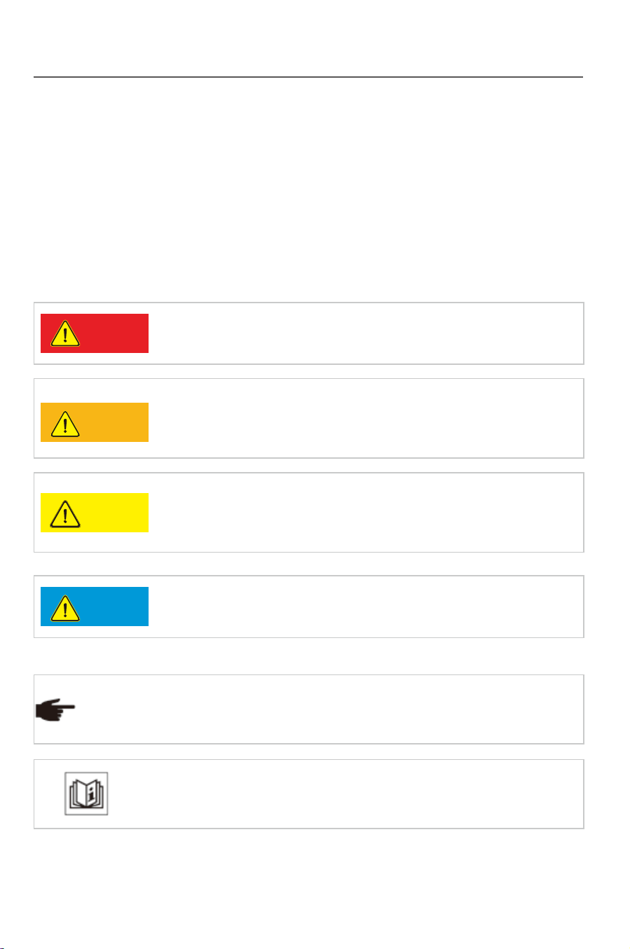
Important safety instruction
Symbols in this manual
To ensure the personal and property safety in using the photovoltaic inverter
and the high efficiency of the product, related safe operation notices are
provided in the manual, and corresponding symbols are used for emphasizing
the importance. These important notices must be fully understood and
followed. Symbols used in this manual are listed below to help you carefully
read and use this manual.
It means a highly potential danger which may cause a
serious personal injury or death directly if this warning is
neglec
ted.
Danger
Warning
Caution
Notice
It means a moderately potential danger which may cause
a serious personal injury or death directly if this warring is
neglected.
It means a lightly potential danger which may cause a light
or moderate personal injury or serious property loss if this
warning is neglected.
It means a potential risk which may cause device
malfunction or property loss if this warning is neglected.
It means an additional notice emphasizing or complementing the
content, or providing a tip for optimizing the product operation,
and further helps you solve some problems or save some time.
Tip
It means a helpful reference or notice.
Introduction
This manual provides the installation, operation and maintenance of
PV grid-connected inverters TP 10KTL- TP 20KTL . The following models
of inverter are related:
●TP10KTL ●TP12KTL ●TP15KTL ●TP17KTL ●TP20KTL
Introduction
Applicable Models
Revised version No. Date Description
XQ-UMT1.0.0EN 2017.02.27 Rev.1
Revision
Important safety instruction
Symbols in this manual
To ensure the personal and property safety in using the photovoltaic inverter
and the high efficiency of the product, related safe operation notices are
provided in the manual, and corresponding symbols are used for emphasizing
the importance. These important notices must be fully understood and
followed. Symbols used in this manual are listed below to help you carefully
read and use this manual.
It means a highly potential danger which may cause a
serious personal injury or death directly if this warning is
neglec
ted.
Danger
Warning
Caution
Notice
It means a moderately potential danger which may cause
a serious personal injury or death directly if this warring is
neglected.
It means a lightly potential danger which may cause a light
or moderate personal injury or serious property loss if this
warning is neglected.
It means a potential risk which may cause device
malfunction or property loss if this warning is neglected.
It means an additional notice emphasizing or complementing the
content, or providing a tip for optimizing the product operation,
and further helps you solve some problems or save some time.
Tip
It means a helpful reference or notice.
Introduction
This manual provides the installation, operation and maintenance of
PV grid-connected inverters TP 10KTL- TP 20KTL . The following models
of inverter are related:
●TP10KTL ●TP12KTL ●TP15KTL ●TP17KTL ●TP20KTL
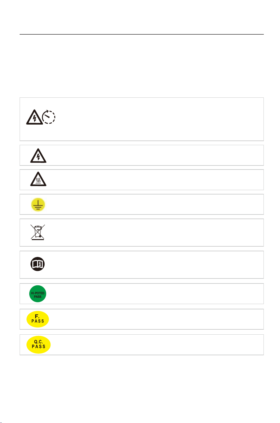
Symbols on the inverter
The inverter is attached with some labels related to operation safety. Please
don’t install the device before carefully reading through and fully
understanding these labels.
It means there is still residual voltage in the inverter! The
capacitor is still electrified after the AC/DC side of the inverter is
cut off, so the inverter cannot be maintained within 10min till the
capacitor is completely discharged.
10 min
Earth line!
Acceptable in the test of insulation and voltage resistance.
Acceptable in the function test.
Acceptable in the quality inspection.
Danger of high voltage and electric shock!
Danger of high temperature and burn injury!
The wasted product must be sent to the authorized collecting
center.
Please carefully read through and fully understand the
instruction manual before using the product.
Contents
1 Safety instruction……………………………………………………………………1
1.1 Before installation…………………………………………………………… 1
1.2 During installation…………………………………………………………… 2
1.3 Operation………………… …………………………………………………2
1.4 Repair………………………………………………………………………… 2
1.5 EMC…………………………………….........……………………………… 3
2 Product description………………………………………………………………4
2.1 Product applicability………………………………………………………… 4
2.2 Circuit structure……………………………………………………………… 4
2.3 Product introduction…………………………………………………………
5
2.3.1 Electrical connecting part………………………….....………………5
2.3.2 Dimensions and weight ……………………………………………… 6
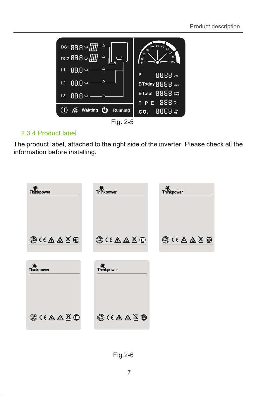
2.3.3 LCD Displaying panel………………………………………………… 6
2.3.4 Product label ………………………………………………………… 7
3 Installation…………………………………………………………………… …… 8
3.1 Safety instruction…………………………………………………………… 8
3.2 Installation procedures……………………………………………………… 8
3.3 Preparation before installation………………………………………… 9
3.3.1 Unpacking and checking……………………………………………… 9
3.3.2 Preparation for tools………………………………………………… 10
3.4 Selection for installation position………………………………………10
3.5 Inverter……………………………………………………………………….12
3.5.1 Installation on a wall………………………………………………12
Introduction Contents

Symbols on the inverter
The inverter is attached with some labels related to operation safety. Please
don’t install the device before carefully reading through and fully
understanding these labels.
It means there is still residual voltage in the inverter! The
capacitor is still electrified after the AC/DC side of the inverter is
cut off, so the inverter cannot be maintained within 10min till the
capacitor is completely discharged.
10 min
Earth line!
Acceptable in the test of insulation and voltage resistance.
Acceptable in the function test.
Acceptable in the quality inspection.
Danger of high voltage and electric shock!
Danger of high temperature and burn injury!
The wasted product must be sent to the authorized collecting
center.
Please carefully read through and fully understand the
instruction manual before using the product.
Contents
1 Safety instruction……………………………………………………………………1
1.1 Before installation…………………………………………………………… 1
1.2 During installation…………………………………………………………… 2
1.3 Operation………………… …………………………………………………2
1.4 Repair………………………………………………………………………… 2
1.5 EMC…………………………………….........……………………………… 3
2 Product description………………………………………………………………4
2.1 Product applicability………………………………………………………… 4
2.2 Circuit structure……………………………………………………………… 4
2.3 Product introduction…………………………………………………………
5
2.3.1 Electrical connecting part………………………….....………………5
2.3.2 Dimensions and weight ……………………………………………… 6
2.3.3 LCD Displaying panel………………………………………………… 6
2.3.4 Product label ………………………………………………………… 7
3 Installation…………………………………………………………………… …… 8
3.1 Safety instruction…………………………………………………………… 8
3.2 Installation procedures……………………………………………………… 8
3.3 Preparation before installation………………………………………… 9
3.3.1 Unpacking and checking……………………………………………… 9
3.3.2 Preparation for tools………………………………………………… 10
3.4 Selection for installation position………………………………………10
3.5 Inverter……………………………………………………………………….12
3.5.1 Installation on a wall………………………………………………12
Introduction Contents

3.6 Electrical connection………………………………………………………14
3.6.1 Electric and electrical system structure……………………………14
3.6.2 Structure of the communication system……………………………16
3.6.3 Wiring terminals and cable specification……………………………18
3.6.4 Steps for electrical connection………………………………………19
3.6.4.1 Steps for DC connection..………………………………………21
3.6.4.2 Steps for AC connection.........................................................23
3.6.4.3 DC /AC teminal Connection....................................................27
3.6.5 Earthing requirement.......................................................................28
4 Trial operation………………………………………………………………….......29
4.1 Check before operation………………………………………………………29
4.1.1 Check for reliabilily of mechanical installation……………………… 29
4.1.2 Check for connecting cables…………………………………………29
4.1.3 Electrical check……………………………………………………… 29
4.2 Electrify the inverter………………………………………………………… 29
5 Human-machine interaction……………...........…………………………………30
5.1 LCD interface………………………………………………………………… 30
5.2 Inverter working mode……………………………………………………… 31
5.2.1 Standing-by mode………………………………………………………32
5.2.2 Ready mode ...............………...………………………………………32
5.2.3 Power generating mode….........................…………………………33
5.2.4 Protection mode..................……..........………………………………33
5.2.5 Fault state………………………………………………………………34
5.3 LCD panel mode….……...………...……………………………………… 35
6 Troubleshooting and maintenance………………………………………………36
6.1 Troubleshooting………………………………………………………………36
93…………………………………………………….……ecnanetniam yliaD 2.6
7
Uninstallation
………………….................................………………………… 40
7.1 Uninstallation steps………………..……………………………………… 40
7.2 Packing……………………………………………………………………… 41
7.3 Storing……………………………………………………………………… 41
7.4 Solution at the termination of service period…………………………… 41
8 Technical parameters……………………………………………………………42
9 Quality assurance……………………………………………………………… 44
44………………………………………………………….....yciloP ytnarraW 1.9
9.2 Exception clause…………………………………………………………… 44
9.3 Warranty card……….............………………………………………………45
10 Contact Think Power……………………………………………………………46
Contents
Contents
5.4 LED blink table
….……...…………..……………………………………… 35

1 Safety instruction
Please contact Think Power if you have any problems .
Tip
TP Series inverters are designed, manufactured and tested as per
international safety standards. However as an electrical and electric product, it
must be installed, operated and maintained strictly according to related safety
notices.
If you have any problems, please contact the nearest service center or
authorized dealer. Please do NOT install or repair the product by anyone who
is not qualified by local authority.
Think Power is not responsible for any damage or loss caused by misuse or
misunderstanding the information in this manual.
Misuse or misoperation may harm:
●
The personal safety of the operator or a third person.
●
The property safety of the inverter or any other property.
Warning
Notice
Warning
1.1 Before installation
The inverter cannot be connected to the grid unless
approved by the electrical authority, and it must be
installed according to the local standard and related
standard for an electrical enterprise.
Please check if there is any damage on the package or
the product before installing.The inverter is electrical
radioactived, Please choose a suitable place for
installing.
Safety instruction
1
Safety instruction
32
1.2 During installation
Keep the PV array covered and the DC circuit breaker
OFF. High voltage will be generated by PV array
exposed under sunshine. All the cables must be
connected firmly.
The inverter must be installed by a qualified electrical
engineer certified by the local authority, and the
installation manual must be read through before
installation. It must be installed according to the local
standard and related standard for an electrical enterprise.
1.3 Operation
●High voltage is a hazard, make sure keep the device
away from children.
●Any touch with the device or terminal may cause
electric shock or fire. Please follow all the safety
instructions.
●A damaged device or system fault can cause electric
shock. Make sure that you have checked the package
and the device before installation to avoid unnecessary
damage or loss.
Be aware of the hot sur
face while the device is running.
1.4 Repair
Completely switch off the connection between the inverter
and the grid, DC side connection. Wait for 10 minutes
until the internal elements are fully discarged.
Do NOT restart the inverter before all the hazards have
been removed. Please contact your local dealer and
always have licensed trader do the repairing.
1.5 EMC
EMC(ElectroMagnetic Compatibility) means the resistance of a device or
system against generating any ElectroMagnetic interference to the
environment without influencing the normal operation in the ElectroMagnetic
environment.
●Immunity to the own noise; Immunity to the internal electrical noise.
●Immunity to the external noise; Immunity to the external ElectroMagnetic
noise.
●Noise radiation level: influence of ElectroMagnetic radiation to the
environment.
●The ElectroMagnet
ic radiation of the inverter is harmful
for health.
●Please never stay within 20cm from a running inverter
for long.
Safety instruction
Notice
Notice
Caution
Notice
Danger
Danger
Danger
Safety instruction
32
1.2 During installation
Keep the PV array covered and the DC circuit breaker
OFF. High voltage will be generated by PV array
exposed under sunshine. All the cables must be
connected firmly.
The inverter must be installed by a qualified electrical
engineer certified by the local authority, and the
installation manual must be read through before
installation. It must be installed according to the local
standard and related standard for an electrical enterprise.
1.3 Operation
●High voltage is a hazard, make sure keep the device
away from children.
●Any touch with the device or terminal may cause
electric shock or fire. Please follow all the safety
instructions.
●A damaged device or system fault can cause electric
shock. Make sure that you have checked the package
and the device before installation to avoid unnecessary
damage or loss.
Be aware of the hot sur
face while the device is running.
1.4 Repair
Completely switch off the connection between the inverter
and the grid, DC side connection. Wait for 10 minutes
until the internal elements are fully discarged.
Do NOT restart the inverter before all the hazards have
been removed. Please contact your local dealer and
always have licensed trader do the repairing.
1.5 EMC
EMC(ElectroMagnetic Compatibility) means the resistance of a device or
system against generating any ElectroMagnetic interference to the
environment without influencing the normal operation in the ElectroMagnetic
environment.
●Immunity to the own noise; Immunity to the internal electrical noise.
●Immunity to the external noise; Immunity to the external ElectroMagnetic
noise.
●Noise radiation level: influence of ElectroMagnetic radiation to the
environment.
●The ElectroMagnet
ic radiation of the inverter is harmful
for health.
●Please never stay within 20cm from a running inverter
for long.
Safety instruction
Notice
Notice
Caution
Notice
Danger
Danger
Danger
Product description Product description
54
2 Product description
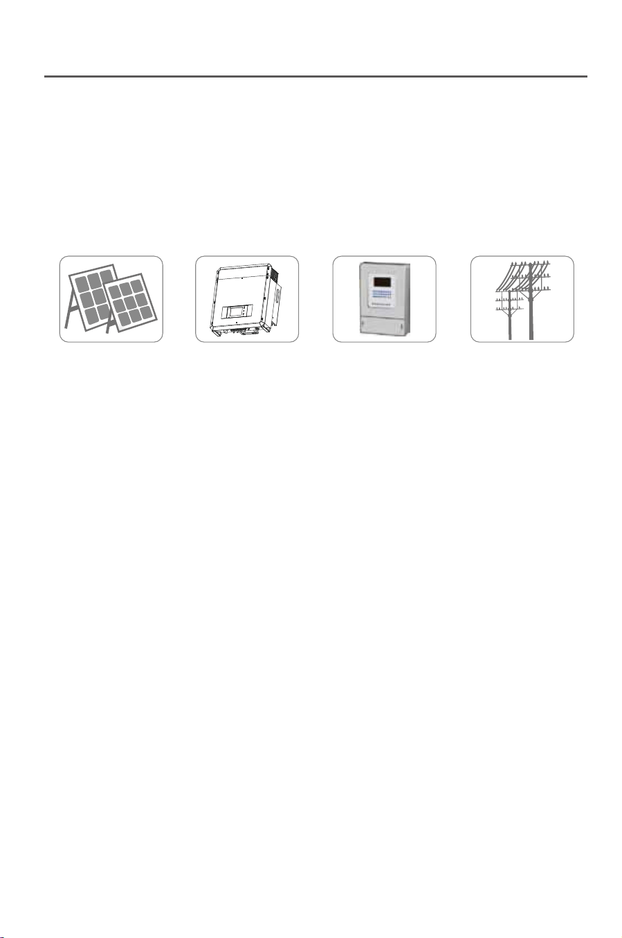
2.1 Product applicability
PV Array Inverter Metering Grid
Fig. 2-1
The research, development and manufacture of TP series are integrated
with the most updated techniques and public confirmed safety regulations.
However, improper operation or misuse may still cause injury or loss.
Instruction and information provided in this manual must be followed all the
time.
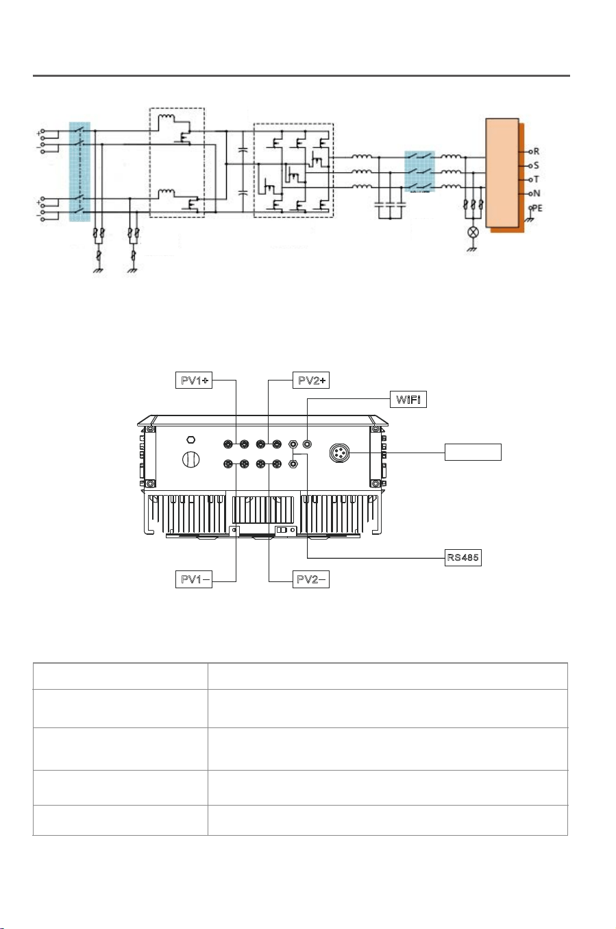
2.2 Circuit structure
Fig.2-2 shows the internal functional diagram o TP series inverter. After the
PV array input enters the voltage boosting circuit via the filter circuit,the input
DC voltage is boosted and stabilized to BUS value for the full-bride inverter
circuit, and in this process, the MPP tracer in the inverter will ensure the DC
energy generated in the photovoltaic array can be used by the inverter circuit
at maximum and the DC current will be conveyed into the grid.
The joint of the input and output EMC can effectively reduce the interference
between the inverter and outside.CPU1 and CPU2 control the inverter
operation and monitor the operation state, and in any abnormal working
condition, it will protect the inverter and external device and personal safety
according to the reserve program thus extremely improve the stability and
reliability of the system.
Fig.2-2
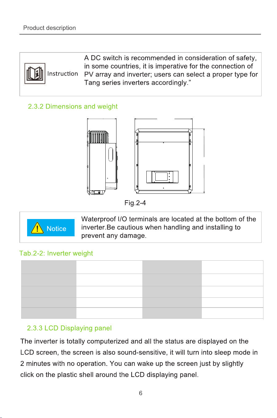
2.3 Product introduction
Fig.2-3
2.3.1 Electrical connecting part
Tab. 2-1: Description for the electrical connecting part of the inverter
Name
DC+ (1/2)
DC- (1/2)
WiFi/RS485
AC Output
Description
The positive part of terminals connecting the
PV array
The negative part of terminals connecting the
PV array
Communication mode
Connected to the grid
TP series inverter, the DC voltage generated in the PV array can be
transformed into AC voltage and supplied to the grid. The PV power
generating system consists of PV arrays,inverters, meters and a public
grid.
PV1+ PV2+
PV1
_
PV2
_
WiFi
RS485
AC Output
DC Switch
DC SPD
DC/DC
Booster Circuit
DC/AC Inverter Circuit LC Rejector
Output
Isolation Relay
LC Rejector
Product description Product description
54
2 Product description
2.1 Product applicability
PV Array Inverter Metering Grid
Fig. 2-1
The research, development and manufacture of TP series are integrated
with the most updated techniques and public confirmed safety regulations.
However, improper operation or misuse may still cause injury or loss.
Instruction and information provided in this manual must be followed all the
time.
2.2 Circuit structure
Fig.2-2 shows the internal functional diagram o TP series inverter. After the
PV array input enters the voltage boosting circuit via the filter circuit,the input
DC voltage is boosted and stabilized to BUS value for the full-bride inverter
circuit, and in this process, the MPP tracer in the inverter will ensure the DC
energy generated in the photovoltaic array can be used by the inverter circuit
at maximum and the DC current will be conveyed into the grid.
The joint of the input and output EMC can effectively reduce the interference
between the inverter and outside.CPU1 and CPU2 control the inverter
operation and monitor the operation state, and in any abnormal working
condition, it will protect the inverter and external device and personal safety
according to the reserve program thus extremely improve the stability and
reliability of the system.
Fig.2-2
2.3 Product introduction
Fig.2-3
2.3.1 Electrical connecting part
Tab. 2-1: Description for the electrical connecting part of the inverter
Name
DC+ (1/2)
DC- (1/2)
WiFi/RS485
AC Output
Description
The positive part of terminals connecting the
PV array
The negative part of terminals connecting the
PV array
Communication mode
Connected to the grid
TP series inverter, the DC voltage generated in the PV array can be
transformed into AC voltage and supplied to the grid. The PV power
generating system consists of PV arrays,inverters, meters and a public
grid.
PV1+ PV2+
PV1
_
PV2
_
WiFi
RS485
AC Output
DC Switch
DC SPD
DC/DC
Booster Circuit
DC/AC Inverter Circuit LC Rejector
Output
Isolation Relay
LC Rejector
6
0
7
m
m
540mm
271.5 mm
Moedl
Moedl
Moedl
Moedl
Moedl
TP10KTL
TP12KTL
TP15KTL
TP17KTL
TP20KTL
Weight
Weight
Weight
Weight
Weight
gK 5.74
47.5 Kg
47.5 Kg
47.5 Kg
47.5 Kg
GRID-TIED SOLAR INVERTER
Wuxi Think Power New Energy Co.,Ltd.
Vdc max :
Vdc mpp :
DC Input Current:
Operation temp
AC Output Rated Power:
Protextive class:
Fac nom:
Power factor:
Vac :
Iac max:
AC Terminal :
Ingress protection
.1 000V d c
50- 800V .2 d c
/17A 17A
IP 65
1000 0W
C lass I
/50 60HZ
0 8 la gging 0 8 le ading. ( )- . ( )
4 V .00 a c
17A
3W N P E+ +
- ±25 60°C
T P 10 K TLMODEL:
.1 000V d c
50- 800 V .2 d c
/71 A 71 A
IP 65
1200 0W
C lass I
/50 60HZ
0 8 la gging 0 8 le ading. ( )- . ( )
4 V .00 a c
20A
3W N P E+ +
- ±25 60°C
T P 12 K TL
.1 000V d c
50- 800 V .2 d c
/20A 20A
IP 65
1500 0W
C lass I
/50 60HZ
0 8 la gging 0 8 le ading. ( )- . ( )
4 V .00 a c
23A
3W N P E+ +
- ±25 60°C
T P 15 K TL
.1 000V d c
50- 800 V .2 d c
/25A 25A
IP 65
1700 0 W
C lass I
/50 60HZ
0 8 la gging 0 8 le ading. ( )- . ( )
4 V .00 a c
25A
3W N P E+ +
- ±25 60°C
T P 17 K TL
.1 000V d c
50- 800 V .2 d c
/25A 25A
IP 65
2000 0W
C lass I
/50 60HZ
0 8 la gging 0 8 le ading. ( )- . ( )
4 V .00 a c
30A
3W N P E+ +
- ±25 60°C
T P 20 K TL
Wuxi Think Power New Energy Co.,Ltd. Wuxi Think Power New Energy Co.,Ltd.
Wuxi Think Power New Energy Co.,Ltd. Wuxi Think Power New Energy Co.,Ltd.
Vdc max :
Vdc mpp :
DC Input Current:
Operation temp
AC Output Rated Power:
Protextive class:
Fac nom:
Power factor:
Vac :
Iac max:
AC Terminal :
Ingress protection
Vdc max :
Vdc mpp :
DC Input Current:
Operation temp
AC Output Rated Power:
Protextive class:
Fac nom:
Power factor:
Vac :
Iac max:
AC Terminal :
Ingress protection
GRID-TIED SOLAR INVERTER
MODEL:
GRID-TIED SOLAR INVERTER
MODEL:
GRID-TIED SOLAR INVERTER
MODEL:
GRID-TIED SOLAR INVERTER
MODEL:
Vdc max :
Vdc mpp :
DC Input Current:
Operation temp
AC Output Rated Power:
Protextive class:
Fac nom:
Power factor:
Vac :
Iac max:
AC Terminal :
Ingress protection
Vdc max :
Vdc mpp :
DC Input Current:
Operation temp
AC Output Rated Power:
Protextive class:
Fac nom:
Power factor:
Vac :
Iac max:
AC Terminal :
Ingress protection

Installation
8
3 Installation
3.1 Safety instruction
3.2 Installation procedures
Fig.3-1
See the following instruction for details.
Start Prepare Inverter install Electrical install
End Test Check
Danger
Installation
9
3.3 Preparation before installation
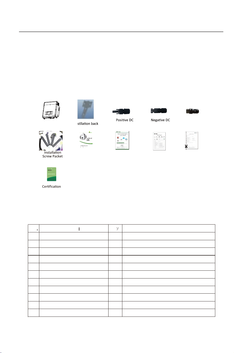
3.3.1 Unpacking and checking
Fig. 3-2
Tab. 3-1: Package list
The DC voltage at the PV array and the AC voltage
at the grid side are both higher than the safe voltage.
It is forbidden to touch any electrified terminal directly.
Make sure the DC side is not electrified before
installation and maintenance.
The inverter must be installed, operated or maintained as per the following
standard and instruction, and it can not be connected to the grid for power
generating unless approved by the local power supply authority, and all
operation must be performed by a qualified electrical engineer.
●All electrical installation must be performed according to the local standard of
electrical installation.
●No internal part except t
he wiring terminal can be touched during installation.
●A running inverter has a high voltage, so no internal operation can be made
within 10 min at least after the AC and DC power
supply of the inverter is cut off
and it is made sure by measuring the DC voltage by a multimeter that the
capacity is fully discharged.
●Take care of the hot surface of the inverter. For example, the heat radiator of
the power semiconductor will be kept in a high temperature after the inverter is
shut down.
●The inverter is deliver without any user’s self-maintenance assembly, so
please contact the local authoriz
ed installation and maintenance technist if
you need to maintain your inverter.
The product is carefully tested and checked before transportation, however it is
still possible to be damaged during transportation, please check the device
again before installation. If any damage, please contact the transportation
agency or directly contact Wuxi Xinqi Power New Energy Technology Co., Ltd.
1
Inverter
1
2
Installation Back Board
1
Certification
3
Positive DC Connector Packet
4
For the connection of PV panel
4
Negative DC Connector Packet
4
For the connection of PV panel
5
AC Connector Packet
1
For the connection of grid
6
4
8
Installation Screw Packet
1
For the back board installation
9
User Manual
1
Please read through carefully
Package List
Check the delivery according
to the package list
No.
Qty
Remark
Description
Warranty Card
Please well keep for filling and returning us
if there become any fault in the inverter
7
1
11
1
10
1
Instructions on connecting your inverter
to your WiFi
WiFi setup Guide
Inverter
In
board
Connector Connector AC Connector
User manual
Package list Warranty card
WiFi setup Guide
TP10KTL
TP17KTL
TP12KTL
TP20KTL
TP15KTL
Installation
8
3 Installation
3.1 Safety instruction
3.2 Installation procedures
Fig.3-1
See the following instruction for details.
Start Prepare Inverter install Electrical install
End Test Check
Danger
Installation
9
3.3 Preparation before installation
3.3.1 Unpacking and checking
Fig. 3-2
Tab. 3-1: Package list
The DC voltage at the PV array and the AC voltage
at the grid side are both higher than the safe voltage.
It is forbidden to touch any electrified terminal directly.
Make sure the DC side is not electrified before
installation and maintenance.
The inverter must be installed, operated or maintained as per the following
standard and instruction, and it can not be connected to the grid for power
generating unless approved by the local power supply authority, and all
operation must be performed by a qualified electrical engineer.
●All electrical installation must be performed according to the local standard of
electrical installation.
●No internal part except t
he wiring terminal can be touched during installation.
●A running inverter has a high voltage, so no internal operation can be made
within 10 min at least after the AC and DC power
supply of the inverter is cut off
and it is made sure by measuring the DC voltage by a multimeter that the
capacity is fully discharged.
●Take care of the hot surface of the inverter. For example, the heat radiator of
the power semiconductor will be kept in a high temperature after the inverter is
shut down.
●The inverter is deliver without any user’s self-maintenance assembly, so
please contact the local authoriz
ed installation and maintenance technist if
you need to maintain your inverter.
The product is carefully tested and checked before transportation, however it is
still possible to be damaged during transportation, please check the device
again before installation. If any damage, please contact the transportation
agency or directly contact Wuxi Xinqi Power New Energy Technology Co., Ltd.
1
Inverter
1
2
Installation Back Board
1
Certification
3
Positive DC Connector Packet
4
For the connection of PV panel
4
Negative DC Connector Packet
4
For the connection of PV panel
5
AC Connector Packet
1
For the connection of grid
6
4
8
Installation Screw Packet
1
For the back board installation
9
User Manual
1
Please read through carefully
Package List
Check the delivery according
to the package list
No.
Qty
Remark
Description
Warranty Card
Please well keep for filling and returning us
if there become any fault in the inverter
7
1
11
1
10
1
Instructions on connecting your inverter
to your WiFi
WiFi setup Guide
Inverter
In
board
Connector Connector AC Connector
User manual
Package list Warranty card
WiFi setup Guide
TP10KTL
TP17KTL
TP12KTL
TP20KTL
TP15KTL
Danger
Notice
Notice
Installation
10
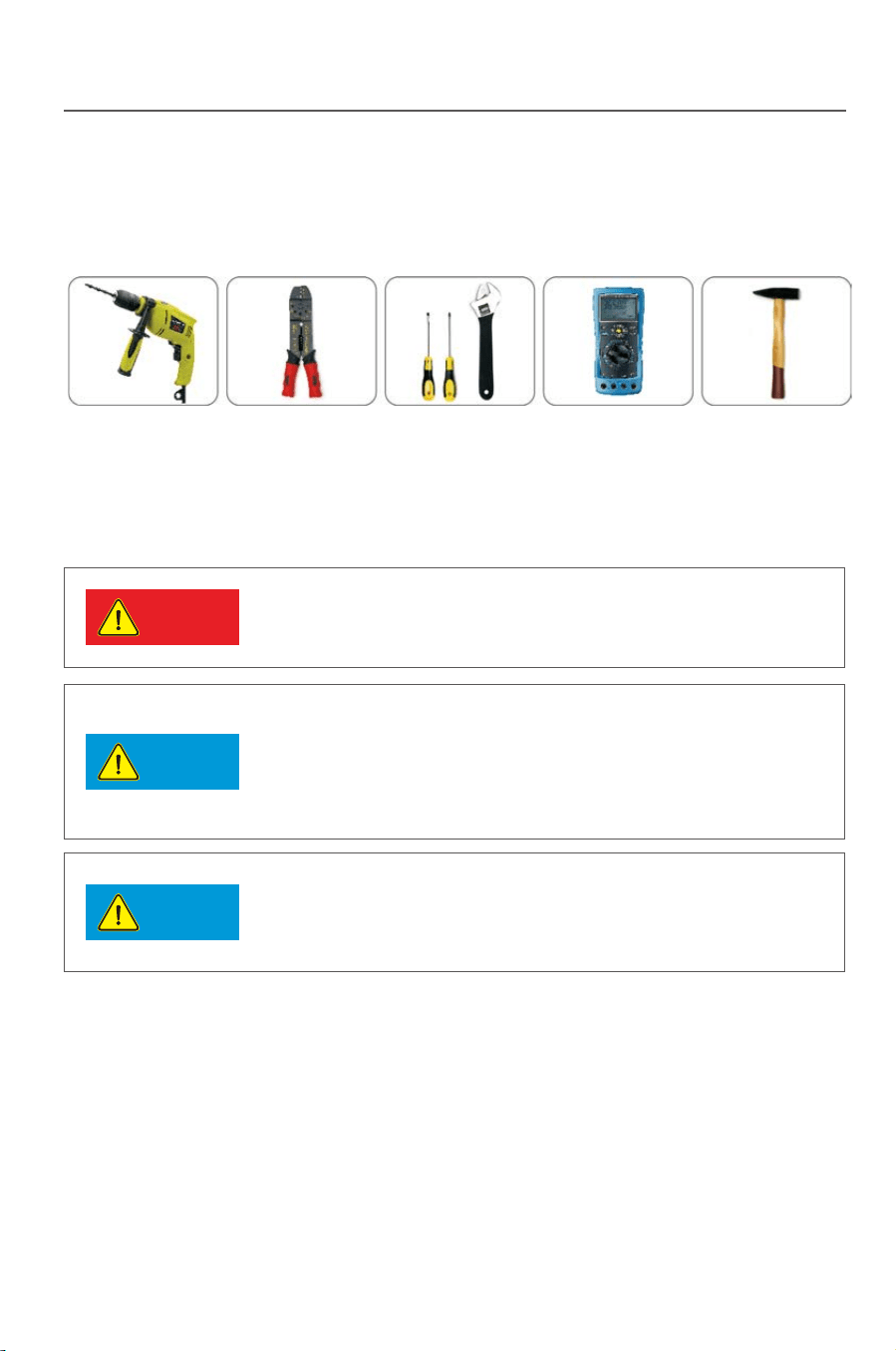
3.3.2 Preparation for tools
The following tools will be used for installing the inverter:
∮12 percussion drill Press pinchers Screw driver and wrench Multimeter Hammer
Fig.3-3
3.4 Selection for a installation position
●
●
11
Detailed requirement for installation position:
※
※
※
※
※
※
※
※
※
※
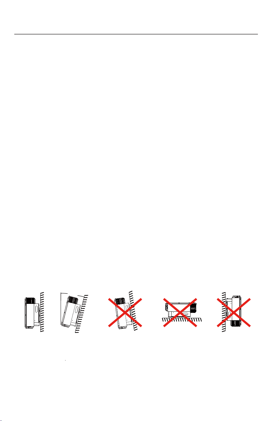
Fig.3-4
Installation
The inverter with a protection level of IP65 can be installed in the open air.
The inverter can not be installed under direction sunshine, or the internal
temperature of the inverter will be excessively high and thus the inverter
performance will be degraded for protecting the internal elements; or even
the temperature protection will be activated by the excessively high
temperature.
The inverter shall be installed in a cool & dry place with temperature from
-25℃
- +60℃;The environmental relative humidity is not higher than 95%
and without any condensation.
The inverter LCD shall be leveled with eyes and with enough space in the
front for inspection.
To avoid of burning or electric shock, the inverter shall be installed beyond
reach of children. The temperature of some parts (e.g. : the heat radiator)
is high when the inverter is running.
Make sure the installation position does not shake.
The inverter shall b
e installed in a well ventilated place to ensure the
normal heat radiation.
The installation place shall be firm enough to support the inverter weight.
The inverter shall be installed on a vertical wall, or within 15°at most if
backwards to the wall.
Connecting terminal is located at the bottom.
Some parts ( e.g.: heat radiator) of the inverter runs with
a high temperature, so it is not suitable for installing near
inflammables or explosives.
When selecting an installation position, please avoid the influence
of noise and electromagnetic radiation to the environment.
The inverter can not be installed near any place of high external
electromagnetic radiation(e.g.: a TV tower, communication signal
tower or HV cables).
The inverter performance will be degraded if the environmental
temperature is 45℃ above. Make sure the inverter
is installed in a
well ventilated place so that the power generation can be
maximized.
Max 15°
Danger
Notice
Notice
Installation
10
3.3.2 Preparation for tools
The following tools will be used for installing the inverter:
∮12 percussion drill Press pinchers Screw driver and wrench Multimeter Hammer
Fig.3-3
3.4 Selection for a installation position
●
●
11
Detailed requirement for installation position:
※
※
※
※
※
※
※
※
※
※
Fig.3-4
Installation
The inverter with a protection level of IP65 can be installed in the open air.
The inverter can not be installed under direction sunshine, or the internal
temperature of the inverter will be excessively high and thus the inverter
performance will be degraded for protecting the internal elements; or even
the temperature protection will be activated by the excessively high
temperature.
The inverter shall be installed in a cool & dry place with temperature from
-25℃
- +60℃;The environmental relative humidity is not higher than 95%
and without any condensation.
The inverter LCD shall be leveled with eyes and with enough space in the
front for inspection.
To avoid of burning or electric shock, the inverter shall be installed beyond
reach of children. The temperature of some parts (e.g. : the heat radiator)
is high when the inverter is running.
Make sure the installation position does not shake.
The inverter shall b
e installed in a well ventilated place to ensure the
normal heat radiation.
The installation place shall be firm enough to support the inverter weight.
The inverter shall be installed on a vertical wall, or within 15°at most if
backwards to the wall.
Connecting terminal is located at the bottom.
Some parts ( e.g.: heat radiator) of the inverter runs with
a high temperature, so it is not suitable for installing near
inflammables or explosives.
When selecting an installation position, please avoid the influence
of noise and electromagnetic radiation to the environment.
The inverter can not be installed near any place of high external
electromagnetic radiation(e.g.: a TV tower, communication signal
tower or HV cables).
The inverter performance will be degraded if the environmental
temperature is 45℃ above. Make sure the inverter
is installed in a
well ventilated place so that the power generation can be
maximized.
Max 15°
Installation
Fig.3-8
Fig.3-7
4)Fix the back board to the wall using the tapping screws tightly.
7) The installation is finished
13
Installation
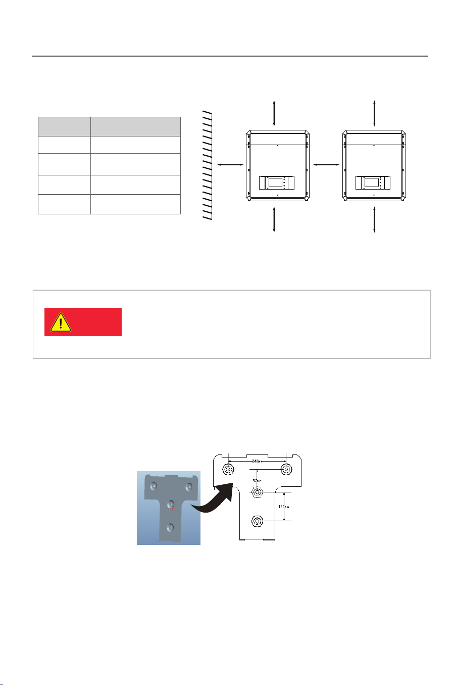
12
Tab.3-2: Effective spacing dimensions
Fig. 3-5
3.5 Inverter installation
3.5.1 Installation Guide
Fig. 3-6
Danger
1) Take out the back board and fix it to the wall; then peel the four logos
on the back board and attach them to the wall through the hole. Thus the
installation holes are marked.
Please check that the open circuit voltage, short circuit
current and maximum power at STC of the PV array are
within the capacity of the solar inverter.
The full load MPPT voltage range is within the
450V-800V.
2) Drill holes in the marked position as per the size of expansion screws.
3) Insert the expansion tubes into the hole, knock the tubes into the hole and
make them level with the wall surface.
5) Keep the inverter tilts slight upward, and attach it to the wall bracket slightly
to the top of its final position, and then visually check if the inverter is correctly
installed on the bayonet.
6) After installing the inverter, adjust the screw on the back of the box to
ensure that the inverter is parallel to the wall
.
Position Min.size(cm)
Front 20CM
40CM
40CM
50CM
Lateral
Top
Bottom
40mm40mm
40mm
40mm
50mm
50mm
3-9
Fig.3-9

Installation
Fig.3-8
Fig.3-7
4)Fix the back board to the wall using the tapping screws tightly.
7) The installation is finished
13
Installation
12
Tab.3-2: Effective spacing dimensions
Fig. 3-5
3.5 Inverter installation
3.5.1 Installation Guide
Fig. 3-6
Danger
1) Take out the back board and fix it to the wall; then peel the four logos
on the back board and attach them to the wall through the hole. Thus the
installation holes are marked.
Please check that the open circuit voltage, short circuit
current and maximum power at STC of the PV array are
within the capacity of the solar inverter.
The full load MPPT voltage range is within the
450V-800V.
2) Drill holes in the marked position as per the size of expansion screws.
3) Insert the expansion tubes into the hole, knock the tubes into the hole and
make them level with the wall surface.
5) Keep the inverter tilts slight upward, and attach it to the wall bracket slightly
to the top of its final position, and then visually check if the inverter is correctly
installed on the bayonet.
6) After installing the inverter, adjust the screw on the back of the box to
ensure that the inverter is parallel to the wall
.
Position Min.size(cm)
Front 20CM
40CM
40CM
50CM
Lateral
Top
Bottom
40mm40mm
40mm
40mm
50mm
50mm
3-9
Fig.3-9
Installation
14
15
Tab.3-4: suggested RCD parameter
Suggested max power input
Number of
inverter(s)/parallel Suggested RCD parameter(mA)
1
2
3
......
n
≥50×1
≥50×2
≥50×3
......
≥50×n
No load can be directly connected to the output side of the inverter.
Installation
-Each string of solar panels in series should be of same type and specification.
-Open Circuit Voltage of each string should not exceed 1000VDC
-The two string of same MPP tracker should have same number of solar panels.
Take Model.TP20KTL as example, the panel power of each MPP tracker should
not exceed 11kw, the total power of inverter should not exceed 22kw.
Recommended Voltage/Current for AC Breaker is 400V/60V.
If the inverter is equipped with “AC Breaker including the RCD”, the parameter
of the RCD refers to the following:
Danger
Warning
3.6 Electrical connection
After the inverter is correctly installed on the wall or support, the next step is the
electrical connection for the inverter. Electrical connection must be performed
according to related safety standards.
A misoperation electrical connection may cause personal injury or
death or damage the inverter irreversibly. Wiring operation must be
performed by a qualified electrical engineer.
All electrical installation must be complying with local and national
electrical standards.
Warning
Warning
The inverter cannot be connected to the grid unless approved
by the local electrical authority and all electrical connections
are completed by a qualified electrical engineer.
Please use cables of specification recommended by us,
or the system safety may be deraded.
The electrical connection for an inverter covers electrical cable connection and
communication cable connection.
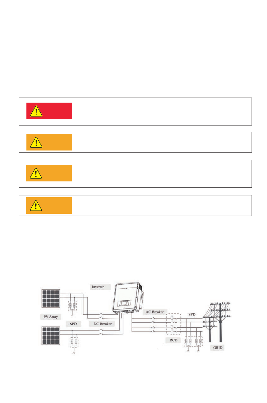
3.6.1 Electric and electrical system structure
The electric and electrical connection for the whole solar energy power
generation system is shown as below:
Fig.3-10
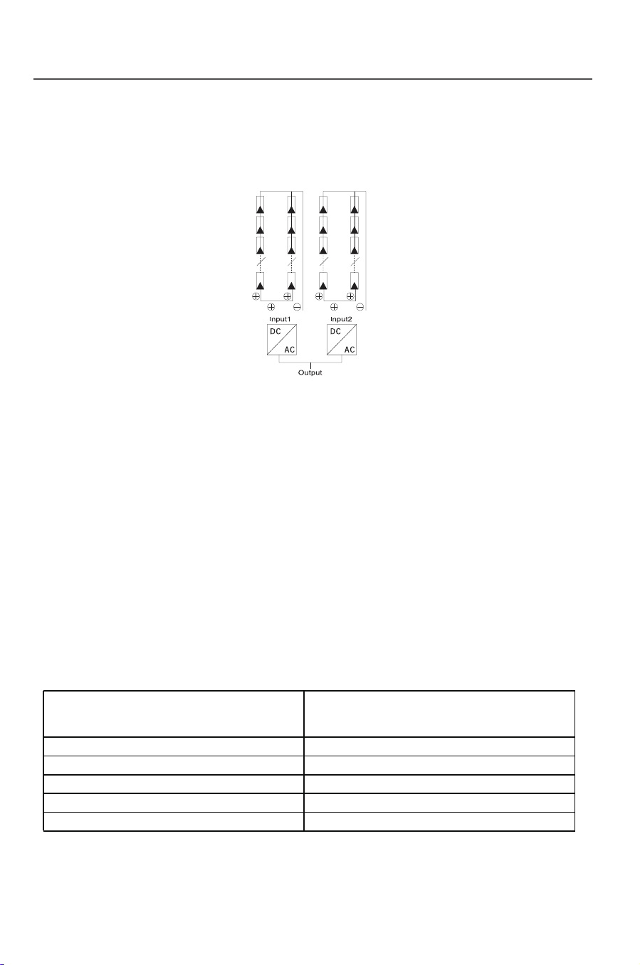
There are two independent MPP trackers in inverter, each MPP tracker has two
pairs of DC input terminals. The connection type refers to Fig.3-11. Keep DCt:
switch in an “OFF” state and make sure that:
Fig.3-11
Installation
14
15
Tab.3-4: suggested RCD parameter
Suggested max power input
Number of
inverter(s)/parallel Suggested RCD parameter(mA)
1
2
3
......
n
≥50×1
≥50×2
≥50×3
......
≥50×n
No load can be directly connected to the output side of the inverter.
Installation
-Each string of solar panels in series should be of same type and specification.
-Open Circuit Voltage of each string should not exceed 1000VDC
-The two string of same MPP tracker should have same number of solar panels.
Take Model.TP20KTL as example, the panel power of each MPP tracker should
not exceed 11kw, the total power of inverter should not exceed 22kw.
Recommended Voltage/Current for AC Breaker is 400V/60V.
If the inverter is equipped with “AC Breaker including the RCD”, the parameter
of the RCD refers to the following:
Danger
Warning
3.6 Electrical connection
After the inverter is correctly installed on the wall or support, the next step is the
electrical connection for the inverter. Electrical connection must be performed
according to related safety standards.
A misoperation electrical connection may cause personal injury or
death or damage the inverter irreversibly. Wiring operation must be
performed by a qualified electrical engineer.
All electrical installation must be complying with local and national
electrical standards.
Warning
Warning
The inverter cannot be connected to the grid unless approved
by the local electrical authority and all electrical connections
are completed by a qualified electrical engineer.
Please use cables of specification recommended by us,
or the system safety may be deraded.
The electrical connection for an inverter covers electrical cable connection and
communication cable connection.
3.6.1 Electric and electrical system structure
The electric and electrical connection for the whole solar energy power
generation system is shown as below:
Fig.3-10
There are two independent MPP trackers in inverter, each MPP tracker has two
pairs of DC input terminals. The connection type refers to Fig.3-11. Keep DCt:
switch in an “OFF” state and make sure that:
Fig.3-11
Installation
16 17
3.6.2 Structure of the communication system
TP series inverters support two flexible communication modes: Standard
Wifi communication and optional RS485 communication. The topological structure
of RS485 communication is as below. (Wifi connection refers to Wifi Setup Guide)
If you have any question when reading the following information,
please do no hesitate to contact Thinkpower.
Tip
RS485 communication
The RS485 communication supports ModBus Protocol. Following is detailed
connection steps.
●
Fig.3-12
Fig.3-13
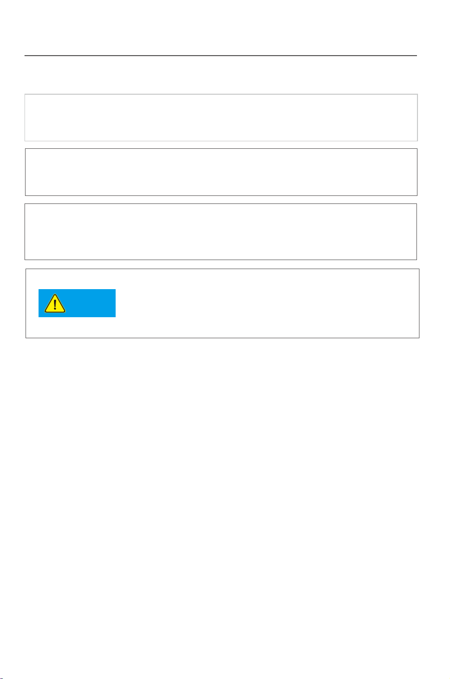
2) Communication between multi-device and a PC
See the figure below for the connecting method. Connect RS485 terminals of
inverters in parallel. Connect 3/4 terminals of the first inverter to A/B terminals
on RS485/USB switch, and then connect the other end of the switch to computer.
The maximum number of RS485 communication devices is 32 units.
The“Multi-device communication mode 2”with RS485 and WIFI is
applicable for centralized installation where wiring is not convenient
between the computer and devices.
Tip
Tip
Tip
RS485/USB switch module and WIFI wireless module are serial products
orderable from Xinqi Power RS485/USB switch module can be
purchased by the user of own.
If RS485 communication mode is selected, it is recommended to use
two-core dual-twisted shield cable. The recommended specification is
RVVP2*1.0. The maximum transmission distance of RS485
communication mode is 1200m.
Installation
RS485
RS485/USB
RS485 RS485 RS485
RS485/USB
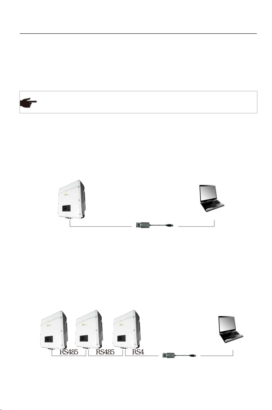
1) Communication between a single device and a PC
See the figure below for the connecting method. Connect 3/4 terminals of
inverter to A/B terminals on RS485/USB switch, and then connect the other
end of the switch to computer.
No load can be directly connected to the output side of the inverter.
Notice
WIFI wireless communication is functioning within 400m
in an opening distance, but interference and barrier shall
be put into consideration because the actual transmission
distance is influenced by the installation field and external
interference.
Installation
16 17
3.6.2 Structure of the communication system
TP series inverters support two flexible communication modes: Standard
Wifi communication and optional RS485 communication. The topological structure
of RS485 communication is as below. (Wifi connection refers to Wifi Setup Guide)
If you have any question when reading the following information,
please do no hesitate to contact Thinkpower.
Tip
RS485 communication
The RS485 communication supports ModBus Protocol. Following is detailed
connection steps.
●
Fig.3-12
Fig.3-13
2) Communication between multi-device and a PC
See the figure below for the connecting method. Connect RS485 terminals of
inverters in parallel. Connect 3/4 terminals of the first inverter to A/B terminals
on RS485/USB switch, and then connect the other end of the switch to computer.
The maximum number of RS485 communication devices is 32 units.
The“Multi-device communication mode 2”with RS485 and WIFI is
applicable for centralized installation where wiring is not convenient
between the computer and devices.
Tip
Tip
Tip
RS485/USB switch module and WIFI wireless module are serial products
orderable from Xinqi Power RS485/USB switch module can be
purchased by the user of own.
If RS485 communication mode is selected, it is recommended to use
two-core dual-twisted shield cable. The recommended specification is
RVVP2*1.0. The maximum transmission distance of RS485
communication mode is 1200m.
Installation
RS485
RS485/USB
RS485 RS485 RS485
RS485/USB
1) Communication between a single device and a PC
See the figure below for the connecting method. Connect 3/4 terminals of
inverter to A/B terminals on RS485/USB switch, and then connect the other
end of the switch to computer.
No load can be directly connected to the output side of the inverter.
Notice
WIFI wireless communication is functioning within 400m
in an opening distance, but interference and barrier shall
be put into consideration because the actual transmission
distance is influenced by the installation field and external
interference.
Installation
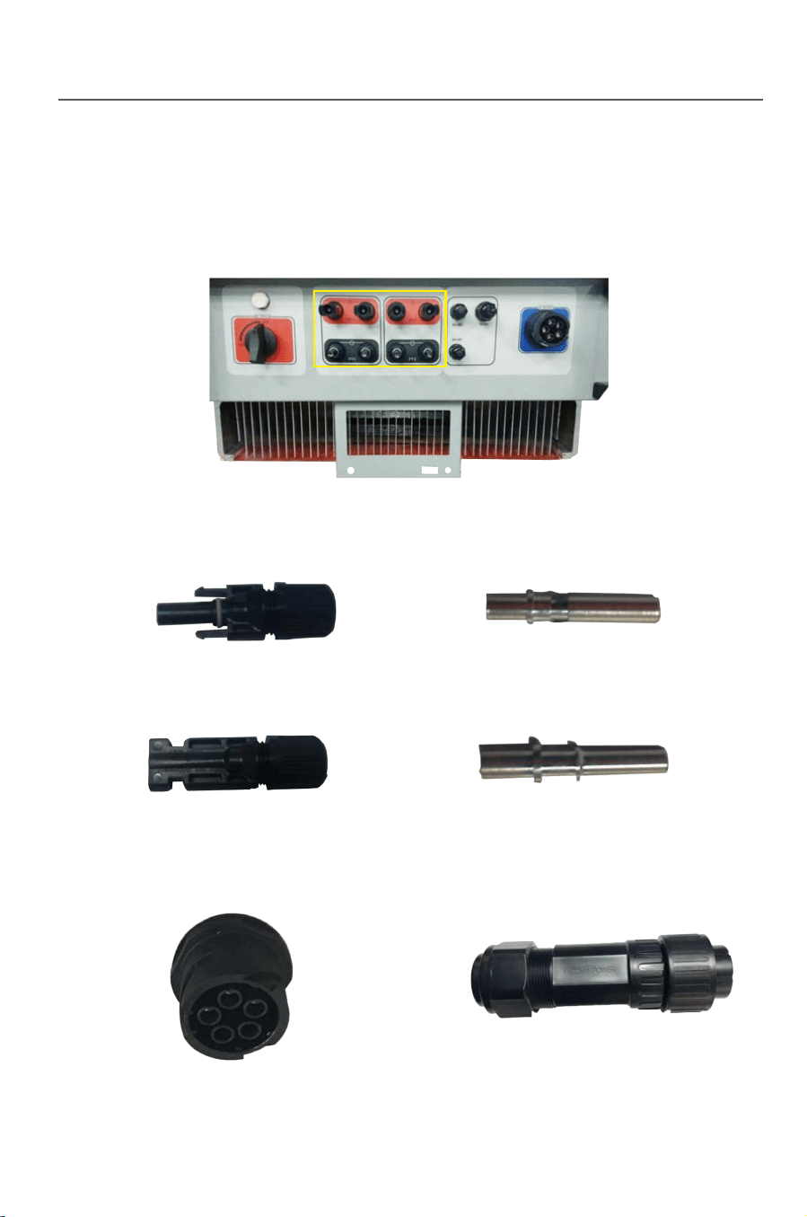
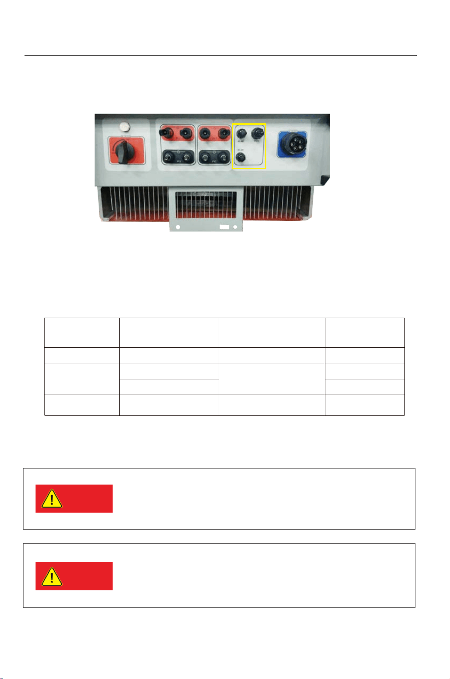
Installation
18
3.6.3 Wiring terminals and cable specification
1) DC wiring terminals
Fig.3-15 Fig.3-16
Fig.3-17 Fig.3-18
19
3) Communication terminals
2) AC terminals
Fig.3-14
Fig.3-19 Fig.3-20
Fig.3-21
The DC side of inverter has 4 pairs of terminals in total.See the figure below:
4) Cables of the following specification will be equipped by the user.
Tab.3-5: Recommended cable specification
DC cable
AC cable
cable (RS485)
Name
Model Recommended cable type
Recommended wire
diameter mm
All of the above cables are copper wire
TP10KTL-TP20KTL
TP10KTL-TP20KTL
TP10KTL-TP12KTL
TP15KTL-TP20KTL
4 core outdoor cable
Photovoltaic cable
2 core outdoor twisted-pair
shielded wire
4mm
3*4mm +1*2.5mm
3*6mm +1*4mm
2*1mm
2
2
2
2
2
2
2
Danger
Danger
3.6.4 Steps for electrical connection
If the inverter has been electrified and tested before
connection, wiring can not be performed unless the AC and
DC power supplies are cut off for 10min and a multimeter
shows that the DC side is tatally discharged.
Please cover the PV array by lightproof material or switch
off the DC circuit breaker before electrical connection. A
dangerous voltage will be generated by the PV array
exposed in the shine.
Installation
Installation
18
3.6.3 Wiring terminals and cable specification
1) DC wiring terminals
Fig.3-15 Fig.3-16
Fig.3-17 Fig.3-18
19
3) Communication terminals
2) AC terminals
Fig.3-14
Fig.3-19 Fig.3-20
Fig.3-21
The DC side of inverter has 4 pairs of terminals in total.See the figure below:
4) Cables of the following specification will be equipped by the user.
Tab.3-5: Recommended cable specification
DC cable
AC cable
cable (RS485)
Name
Model Recommended cable type
Recommended wire
diameter mm
All of the above cables are copper wire
TP10KTL-TP20KTL
TP10KTL-TP20KTL
TP10KTL-TP12KTL
TP15KTL-TP20KTL
4 core outdoor cable
Photovoltaic cable
2 core outdoor twisted-pair
shielded wire
4mm
3*4mm +1*2.5mm
3*6mm +1*4mm
2*1mm
2
2
2
2
2
2
2
Danger
Danger
3.6.4 Steps for electrical connection
If the inverter has been electrified and tested before
connection, wiring can not be performed unless the AC and
DC power supplies are cut off for 10min and a multimeter
shows that the DC side is tatally discharged.
Please cover the PV array by lightproof material or switch
off the DC circuit breaker before electrical connection. A
dangerous voltage will be generated by the PV array
exposed in the shine.
Caution
Notice
Installation
20 21
3.6.4.1 Steps for DC connection
Tip
Tip
Tip
Tip
Fig.3-22
Fig.3-23
Steps for DC cable wiring
Installation
DC cable between the inverter and the assembly shall be the
special PV cable. The voltage drop from the terminal box to the
inverter is about 1-2%. It is recommended the inverter is
installed on the assembly support for generation to reduce the
cable cost and the DC loss.
High performance and high quality PV array shall be used. The
open circuit voltage in the serial array must be lower than the
maximum DC input voltage in the PV grid-tied inverter, and the
working voltage of the serial array must comply with the MPPT
voltage of the serial array must comply with the MPPT voltage
in the PV grid-tied inverter.
● Protect the LCD panel during wiring;
● Protect the LCD panel and other elements from scratch or
damage by cables or tools.
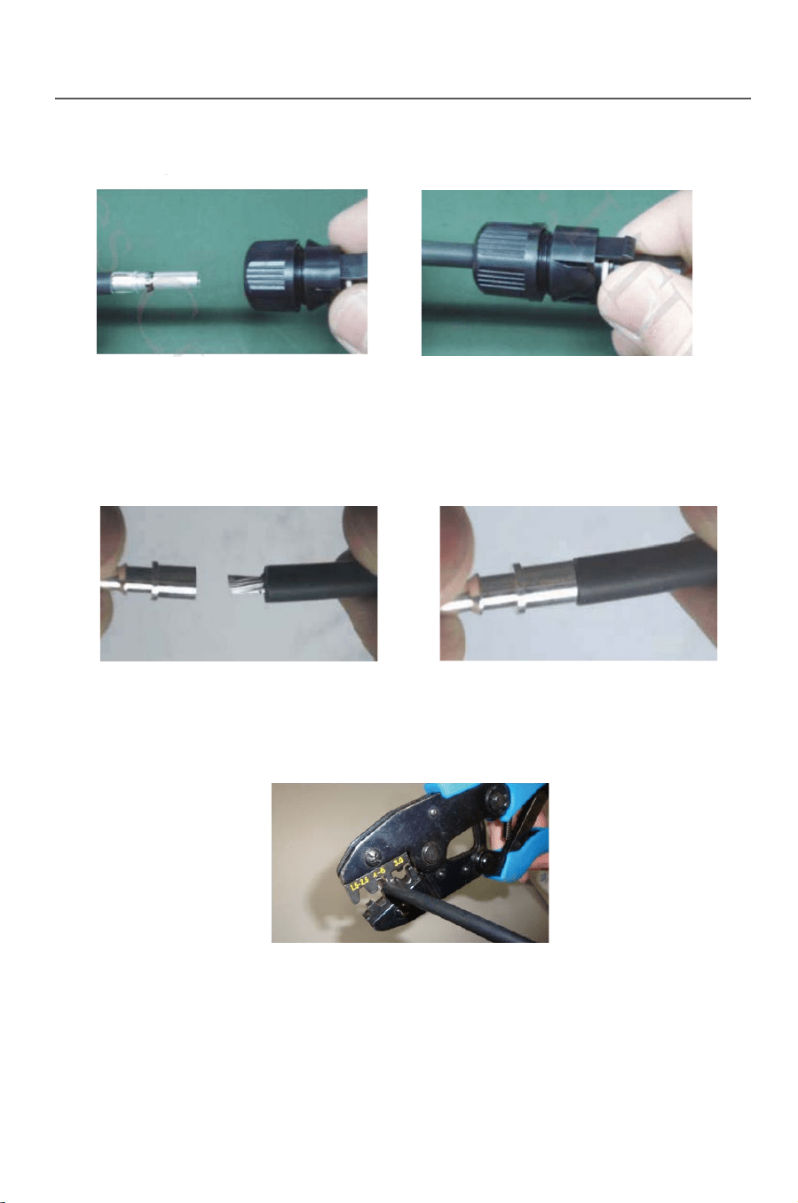
1) Using the striping tool to cut the PV cable, and makes the cooper wire
reveal as 0.7cm.
In order to balance each PV series, Cable shall be with the same
sectional area.
Different colors of cables shall be used for differentiating in
assembling. For example: the positive pole is connected by a red
cable and the negative by a blue cable.
When designing the PV array, make sure the maximum
open circuit voltage is not higher than 1000V at each
series of PV group. Otherwise the inverter will be
damaged irreversibly
2) Insert cable into DC”+” terminal
3) Process crimping.
Fig.3-24 Fig.3-25
Fig.3-26

Caution
Notice
Installation
20 21
3.6.4.1 Steps for DC connection
Tip
Tip
Tip
Tip
Fig.3-22
Fig.3-23
Steps for DC cable wiring
Installation
DC cable between the inverter and the assembly shall be the
special PV cable. The voltage drop from the terminal box to the
inverter is about 1-2%. It is recommended the inverter is
installed on the assembly support for generation to reduce the
cable cost and the DC loss.
High performance and high quality PV array shall be used. The
open circuit voltage in the serial array must be lower than the
maximum DC input voltage in the PV grid-tied inverter, and the
working voltage of the serial array must comply with the MPPT
voltage of the serial array must comply with the MPPT voltage
in the PV grid-tied inverter.
● Protect the LCD panel during wiring;
● Protect the LCD panel and other elements from scratch or
damage by cables or tools.
1) Using the striping tool to cut the PV cable, and makes the cooper wire
reveal as 0.7cm.
In order to balance each PV series, Cable shall be with the same
sectional area.
Different colors of cables shall be used for differentiating in
assembling. For example: the positive pole is connected by a red
cable and the negative by a blue cable.
When designing the PV array, make sure the maximum
open circuit voltage is not higher than 1000V at each
series of PV group. Otherwise the inverter will be
damaged irreversibly
2) Insert cable into DC”+” terminal
3) Process crimping.
Fig.3-24 Fig.3-25
Fig.3-26
Installation
22
4) Put terminal into connector “+”
5) Insert cable into DC “-” terminal
6) Process crimping
7) Put terminal into connector “-”
3.6.4.2 Steps for AC connection
Connect inverter with AC distribution box or public grid by AC output cables.
23
Installation
Fig.3-29 Fig.3-30
Fig.3-27 Fig.3-28
Fig.3-31
Fig.3-32
1)
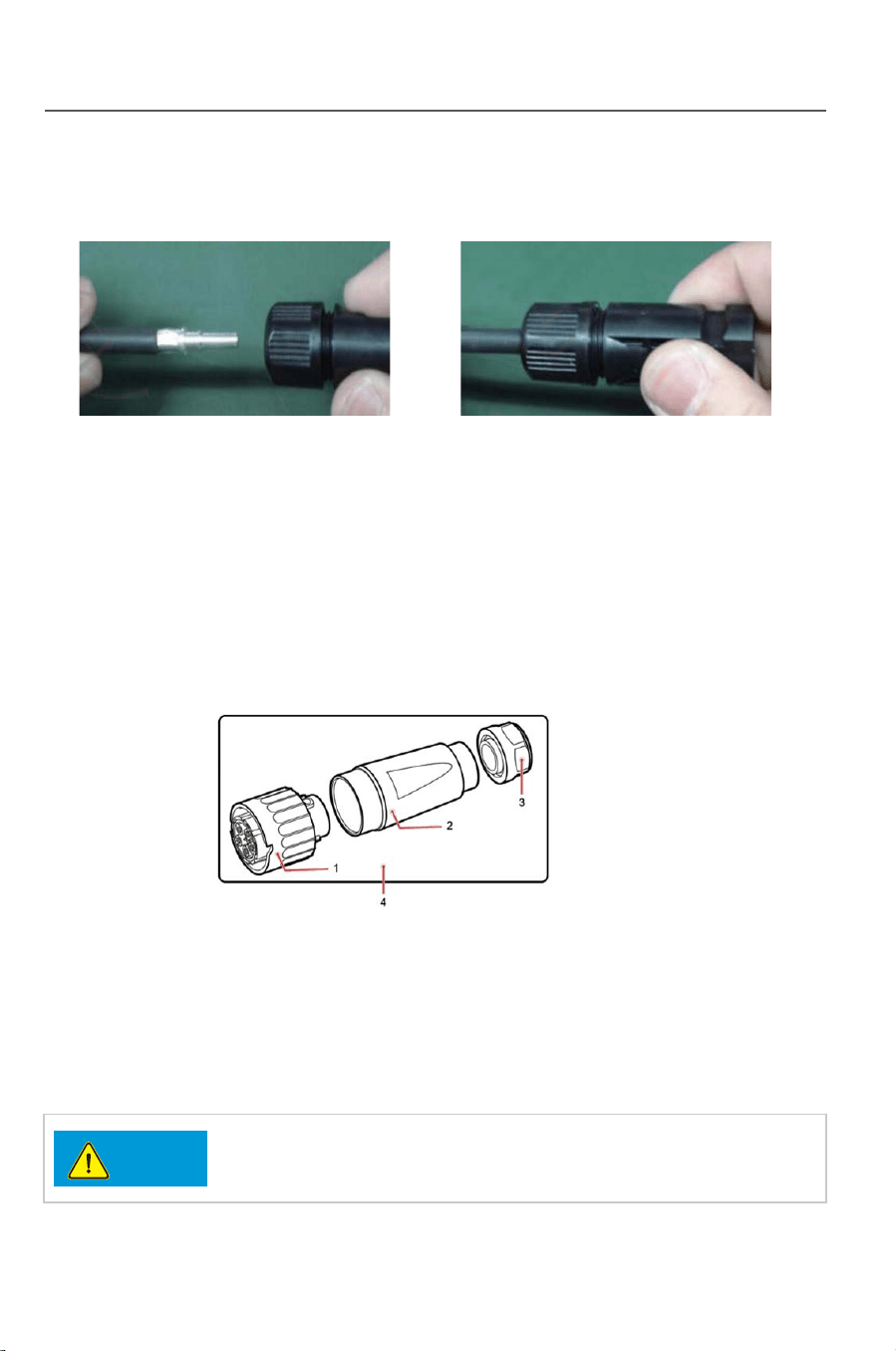
AC output connector contains three parts: plug, adapter and cable gland. See Fig.3-34
1. Plug 2. Adapter 3. Cable gland
Step 1 Remove the cable gland and the adapter from the AC output connector
Step 2 Remove the insulation layer of the AC output cable of an appropriate length
using a wire stripper .
Fig.3-34
Instructure of AC output connector
The three -phase AC input power cables, neutral cable,
and PGND cable must be properly connected.
Notice
Fig.3-33
Installation
22
4) Put terminal into connector “+”
5) Insert cable into DC “-” terminal
6) Process crimping
7) Put terminal into connector “-”
3.6.4.2 Steps for AC connection
Connect inverter with AC distribution box or public grid by AC output cables.
23
Installation
Fig.3-29 Fig.3-30
Fig.3-27 Fig.3-28
Fig.3-31
Fig.3-32
1)
AC output connector contains three parts: plug, adapter and cable gland. See Fig.3-34
1. Plug 2. Adapter 3. Cable gland
Step 1 Remove the cable gland and the adapter from the AC output connector
Step 2 Remove the insulation layer of the AC output cable of an appropriate length
using a wire stripper .
Fig.3-34
Instructure of AC output connector
The three -phase AC input power cables, neutral cable,
and PGND cable must be properly connected.
Notice
Fig.3-33
Installation
24 25
Installation
.
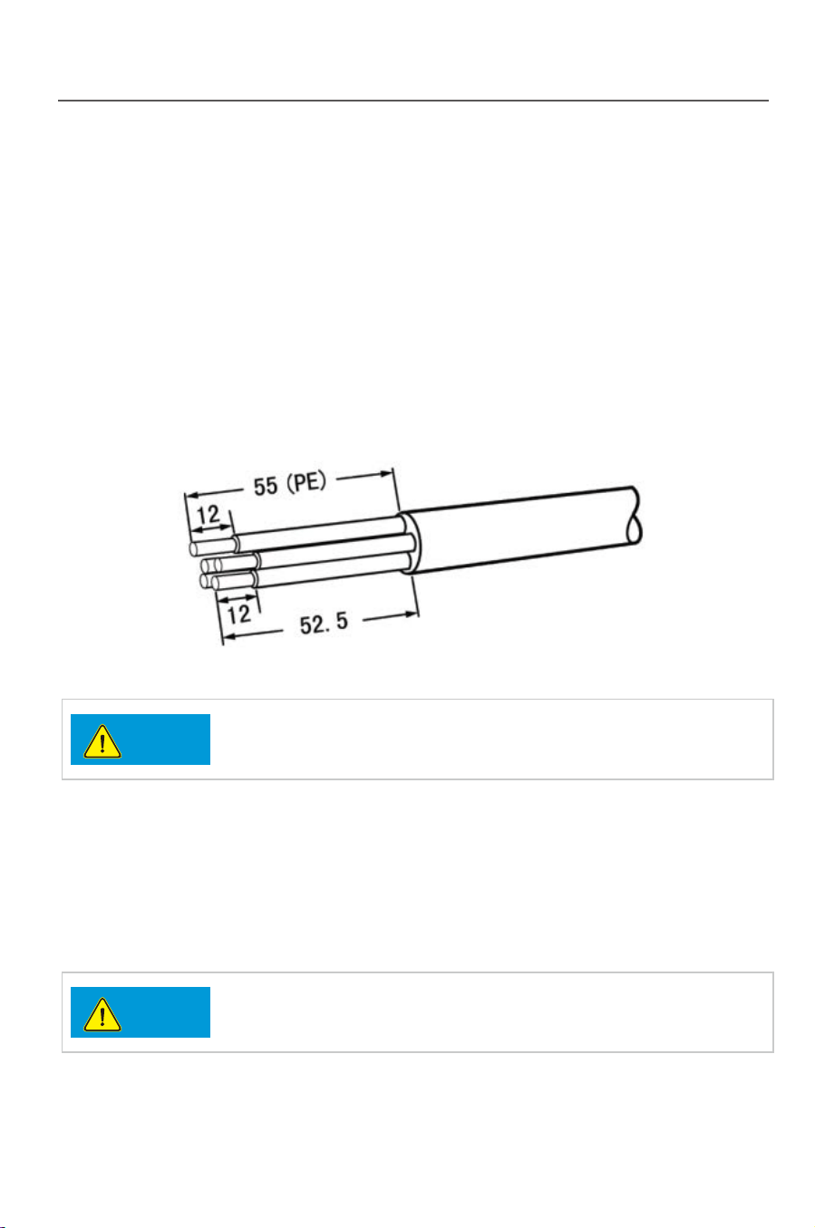
1. Strip the outer jacket of AC output cable by 55 mm
2. Cut the core wires of the cables excluding the PGND cable by 2.5 mm
That is, the core wire of the PGND cable should be 2.5 mm longer than that of
other four cables.
3. Strip the insulation layer of each core wires by 12 mm
Fi gure 3-35 Connecting an AC output power cable (1) (unit: mm)
The preceding figure shows only how to strip cables for the
10KTL to 20KTL
.
Notice
Notice
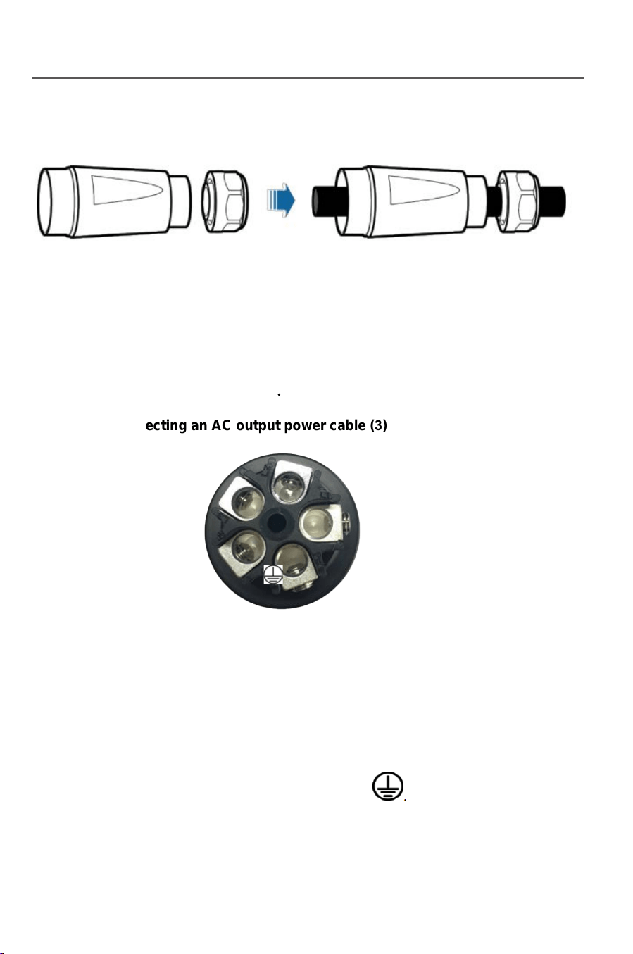
Step 3 Insert AC output cable (L1, L2, L3, N, and PE) into the cable gland and the adapter,
as shown in Figure 3-36.
If the external cable diameter ranges from16mmto20mm,
removeaseal ring from the cable gland before inserting
the power cable into the cable gland and the adapter.
Figure 3-36 Connecting an AC output power cable (2)
Step 4 Loosen the screws inside the coupling nut holes using a flathead screwdriver,
insert the core wires into corresponding holes, and tighten the screws, as shown
in Figure 3-37.
Tighten the screws to a torque of 0.7 N m.
Figure 3-37 Connecting an AC output power cable (3)
Connect L1 to the hole numbered L1.
Connect L2 to the hole numbered L2.
L1
L2
L3
N
Connect L3 to the hole numbered L3.
Connect N to the hole numbered N.
Connect PE to the hole marked .
Step 5 Check that all core wires are properly connected
Installation
24 25
Installation
.
1. Strip the outer jacket of AC output cable by 55 mm
2. Cut the core wires of the cables excluding the PGND cable by 2.5 mm
That is, the core wire of the PGND cable should be 2.5 mm longer than that of
other four cables.
3. Strip the insulation layer of each core wires by 12 mm
Fi gure 3-35 Connecting an AC output power cable (1) (unit: mm)
The preceding figure shows only how to strip cables for the
10KTL to 20KTL
.
Notice
Notice
Step 3 Insert AC output cable (L1, L2, L3, N, and PE) into the cable gland and the adapter,
as shown in Figure 3-36.
If the external cable diameter ranges from16mmto20mm,
removeaseal ring from the cable gland before inserting
the power cable into the cable gland and the adapter.
Figure 3-36 Connecting an AC output power cable (2)
Step 4 Loosen the screws inside the coupling nut holes using a flathead screwdriver,
insert the core wires into corresponding holes, and tighten the screws, as shown
in Figure 3-37.
Tighten the screws to a torque of 0.7 N m.
Figure 3-37 Connecting an AC output power cable (3)
Connect L1 to the hole numbered L1.
Connect L2 to the hole numbered L2.
L1
L2
L3
N
Connect L3 to the hole numbered L3.
Connect N to the hole numbered N.
Connect PE to the hole marked .
Step 5 Check that all core wires are properly connected
Installation
2
6
2
7
Installation
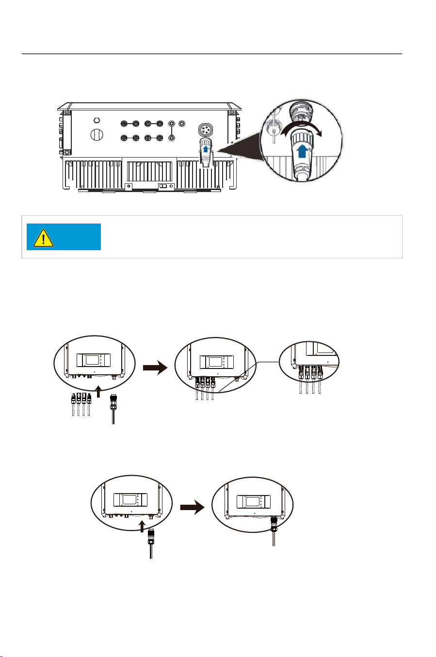
3.6.4.3 DC/AC terminal connection:
1) Make sure that the DC/AC breaker is
2) Insert the DC+/- wiring terminal into corresponding DC+/- terminal.
Fig.3-41
3) Insert the AC wiring terminal into the AC terminal.
4) Switch on the AC breaker.
5) Turn the DC switch to the “ON” state.
Fig.3-42
DC1+ DC1- DC2- DC2+
AC
OUTPUT
DC1+ DC1- DC2- DC2+
DC1+ DC1- DC2- DC2+
AC
OUTPUT
AC
OUTPUT
AC
OUTPUT
.
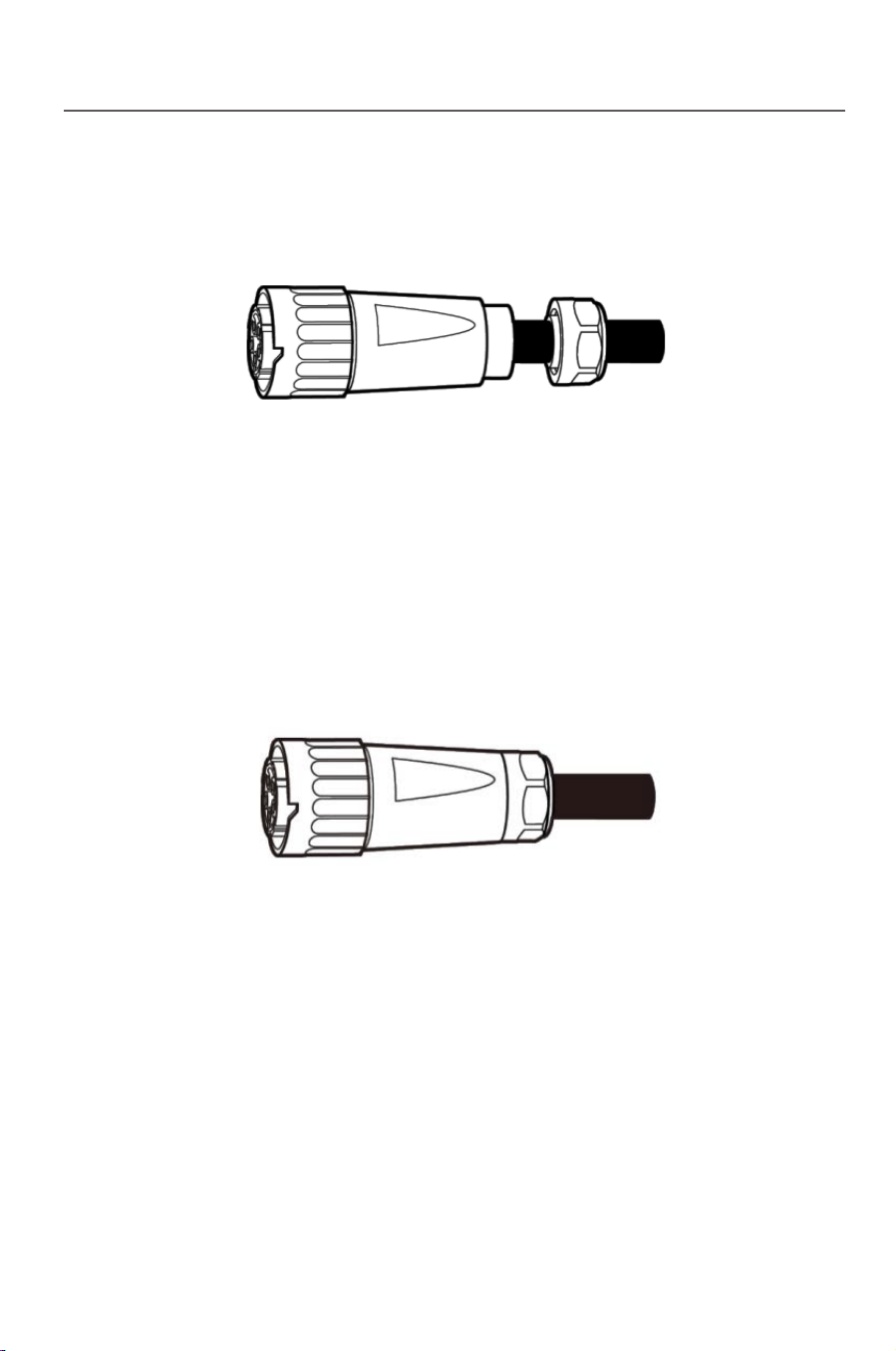
Step 6 Secure the adapter to the coupling nut, as shown in
Figure 3-38 Connecting an AC output power cable (4)
Step 7 Secure the cable gland to the adapter, as shown in Figure 3-39.
Tighten the cable gland to a torque of 5 N.m (You need to use some tool to achieve
this torque)
Figure 3-39 Connecting an AC output power cable (5)
Step 8 Connect the AC output connector to the bayonet coupling of the AC output wiring
terminal on the Inverter and rotate it clockwise until you hear a "click" sound,
as shown in Figure 3-40.
Because no sufficient space is available on the right of the AC terminal, tighten
the terminal using the left hand.
Figure 3-40 Connecting an AC output power cable (6)
The AC output connector securely connects to the AC
output wiring terminal after the bayonet coupling snaps into place.
Notice
Figure 3-38
Installation
2
6
2
7
Installation
3.6.4.3 DC/AC terminal connection:
1) Make sure that the DC/AC breaker is
2) Insert the DC+/- wiring terminal into corresponding DC+/- terminal.
Fig.3-41
3) Insert the AC wiring terminal into the AC terminal.
4) Switch on the AC breaker.
5) Turn the DC switch to the “ON” state.
Fig.3-42
DC1+ DC1- DC2- DC2+
AC
OUTPUT
DC1+ DC1- DC2- DC2+
DC1+ DC1- DC2- DC2+
AC
OUTPUT
AC
OUTPUT
AC
OUTPUT
.
Step 6 Secure the adapter to the coupling nut, as shown in
Figure 3-38 Connecting an AC output power cable (4)
Step 7 Secure the cable gland to the adapter, as shown in Figure 3-39.
Tighten the cable gland to a torque of 5 N.m (You need to use some tool to achieve
this torque)
Figure 3-39 Connecting an AC output power cable (5)
Step 8 Connect the AC output connector to the bayonet coupling of the AC output wiring
terminal on the Inverter and rotate it clockwise until you hear a "click" sound,
as shown in Figure 3-40.
Because no sufficient space is available on the right of the AC terminal, tighten
the terminal using the left hand.
Figure 3-40 Connecting an AC output power cable (6)
The AC output connector securely connects to the AC
output wiring terminal after the bayonet coupling snaps into place.
Notice
Figure 3-38

28
3.6.5 Earthing requirement
29
4 Trial operation
4.1 Check before operation
4.1.1 Check for reliability of mechanical installation
4.1.2 Check for connecting cables
4.1.3 Electrical check
Make sure the grid parameters are complying with the inverters parameters.
4.2 Electrify the inverter
Installation
Trial operation
Warning
Caution
Necessary safety check must be performed before the
inverter is electrified for trial operation!
The inverter is a device with no transformer, neither the
positive nor the negative pole of the PV assembly DC side
can be earthed, or the inverter will not work normally, or even
be damaged irreversibly.
In TP series PV power generating system, all device shells, assembly supports
and the GND terminal of the inverter must be safety and reliably earthed.
Check if the inverter is firmly installed and if all bolts are reliably tightened. For
an inverter installed on a metal supporter, make sure each bolt is tightened and
support has enough load bearing capacity.
Check if all cables in the system are firmly connected without any missed or
wrong connection, and especially check if all positive and negative poles are
correct. If a DC switch is equipped on the inverter, the DC switch shall be turn
to the “OFF” state.
Make sure the DC input voltage of the inverter is lower than 1000V (with the
temperature decrease of the PV array, the open circuit voltage will be
increased, so a residual voltage at the low temperature must be put into
consideration).
The inverter can be started up as per the following steps after all testing and
checking steps are performed.
Switch on the DC breaker, and turn the DC switch to the “ON” state.
Switch on the AC breaker.
See Part 5 of this manual for “Human-machine interaction” after the inverter is
started up. If enough power energy can be generated in the solar array, the
inverter will be started up automatically, and LCD will display the normal status
which means the inverter is successfully started up. If the inverter is not
normally started up, please refer to Part 6 “Troubleshooting and maintenance”.
30
5 Human-machine interaction
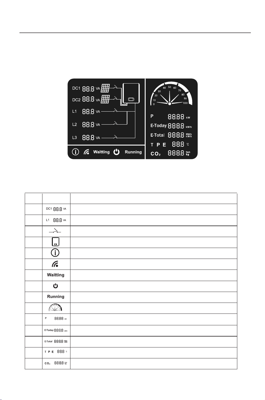
5.1 LCD interface
Fig.5-1
Tab. 5-1: Introduction to symbols on the LCD panel
31
Human-machine interaction Human-machine interaction
SN Symbol Description
1
2
3
4
5
6
7
8
9
10
11
12
13
14
15
It alternately displays the DC voltage and current
It alternately displays the AC voltage and current
It means DC/AC connection
It means the on grid inverter
It means inverter enters into fault mode
It means communication mode of the inverter:
flicker means “connectied”, otherwise “disconnected”
It means the inverter is on ready mode.
It means the DC connection of the inverter is OK.
It means the inverter is working normally.
It means load rate of the inverter.
It indicates the current power.
It indicates the electric quantity of the current day.
It indicates the total electric quantity.
It indicates the current temperature of the inverter.
It indicates the amount of reducing CO2.
Fig. 5-2
Power off
Sleeping
DC
>300v
Td Waiting
Td=10-20S
Standing-by
Power generating
Device fault/environmental abnormity
Fault/protection recovery Th self-detecting
Th=60-70S
Fault/Protection
Device fault/environmental
abnormity
Fault/protection
recovery
Th=self-detect
Th=60-70S
5.2 Inverter working mode
After the inverter is started up, the normal working state will be
switched as per
the chart below:
DC<250v
DC>250v
DC<250v
DC<300v DC>300v
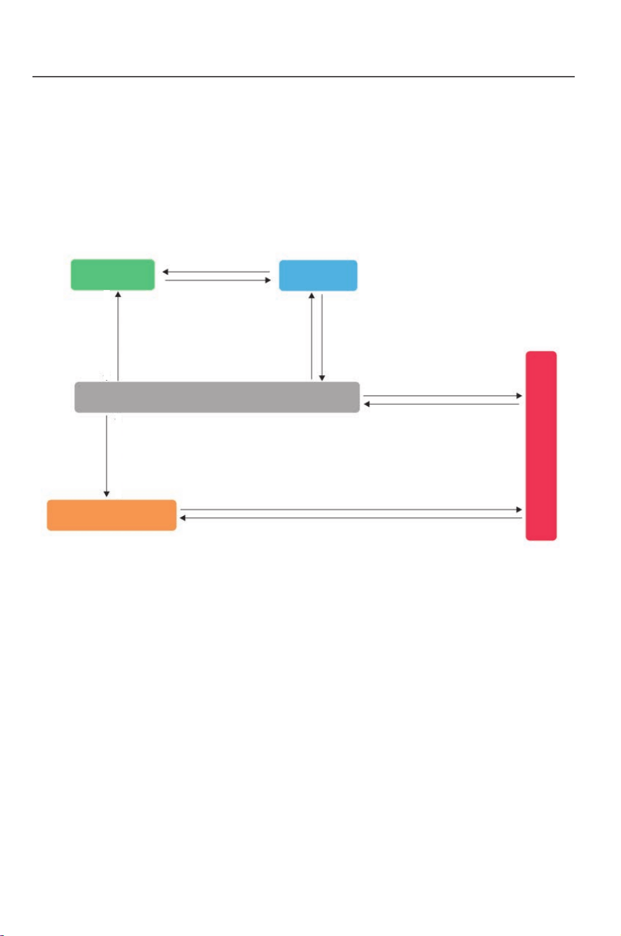
30
5 Human-machine interaction
5.1 LCD interface
Fig.5-1
Tab. 5-1: Introduction to symbols on the LCD panel
31
Human-machine interaction Human-machine interaction
SN Symbol Description
1
2
3
4
5
6
7
8
9
10
11
12
13
14
15
It alternately displays the DC voltage and current
It alternately displays the AC voltage and current
It means DC/AC connection
It means the on grid inverter
It means inverter enters into fault mode
It means communication mode of the inverter:
flicker means “connectied”, otherwise “disconnected”
It means the inverter is on ready mode.
It means the DC connection of the inverter is OK.
It means the inverter is working normally.
It means load rate of the inverter.
It indicates the current power.
It indicates the electric quantity of the current day.
It indicates the total electric quantity.
It indicates the current temperature of the inverter.
It indicates the amount of reducing CO2.
Fig. 5-2
Power off
Sleeping
DC
>300v
Td Waiting
Td=10-20S
Standing-by
Power generating
Device fault/environmental abnormity
Fault/protection recovery Th self-detecting
Th=60-70S
Fault/Protection
Device fault/environmental
abnormity
Fault/protection
recovery
Th=self-detect
Th=60-70S
5.2 Inverter working mode
After the inverter is started up, the normal working state will be
switched as per
the chart below:
DC<250v
DC>250v
DC<250v
DC<300v DC>300v
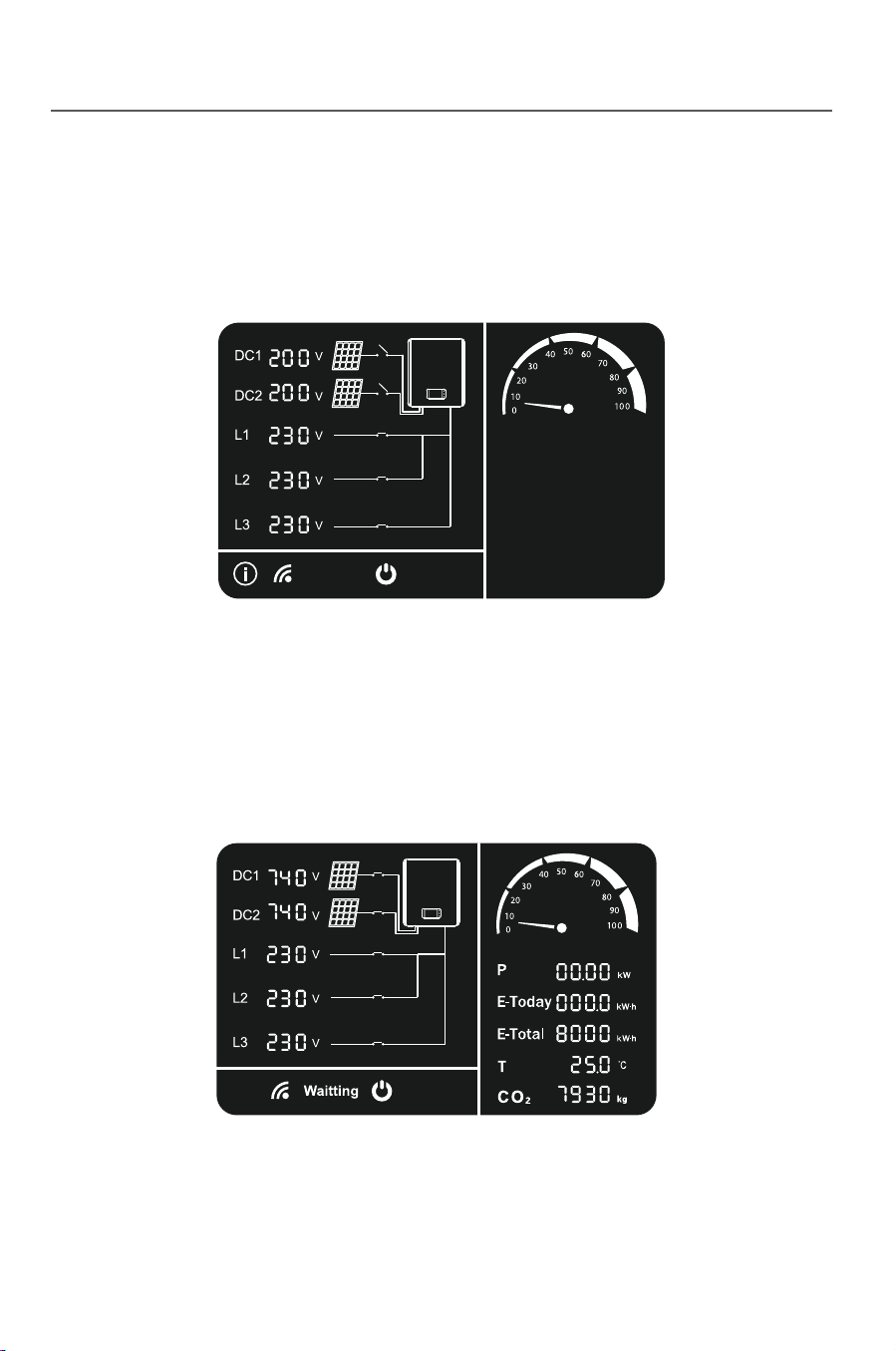
32
5.2.1 Standing-by mode
Fig. 5-3
Fig. 5-4
5.2.2 Ready mode
33
5.2.3 Power generating mode
Fig. 5-5
edom noitcetorP 4.2.5
Fig. 5-6
Human-machine interaction
Human-machine interaction
When the DC voltage is higher than 250V but lower than 300V, the inverter
will enter the sleep mode. In this case, the inverter will keep monitoring the
DC voltage , and will enter the ready mode once it reaches the working
voltage 300V.
When the DC voltage is over 300V, the inverter enter into the ready mode.
In this case, inverter start hardware self-checking,and after the self-checking
is over, the inverter enter power generating mode.
If any external fault such as AC side grid fault is detected by the inverter, the
inverter will stop power generating and enter the protection mode, in this case the
protection indicator on LCD panel will show and display the corresponding
protection code.
Troubleshooting can be performed by the user according to this code. The
inverter will keep monitoring if the external fault is removed, and will keep in the
protection mode unless the fault is removed. It will be reenter the grid-connect
power generating mode one minute later after the fault is removed.
When the external condition satisfies the power generating condition, and the
after the self-checking gets through, the inverter will enter into the power
generating mode.
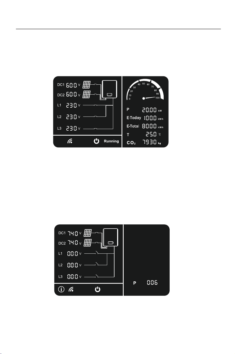
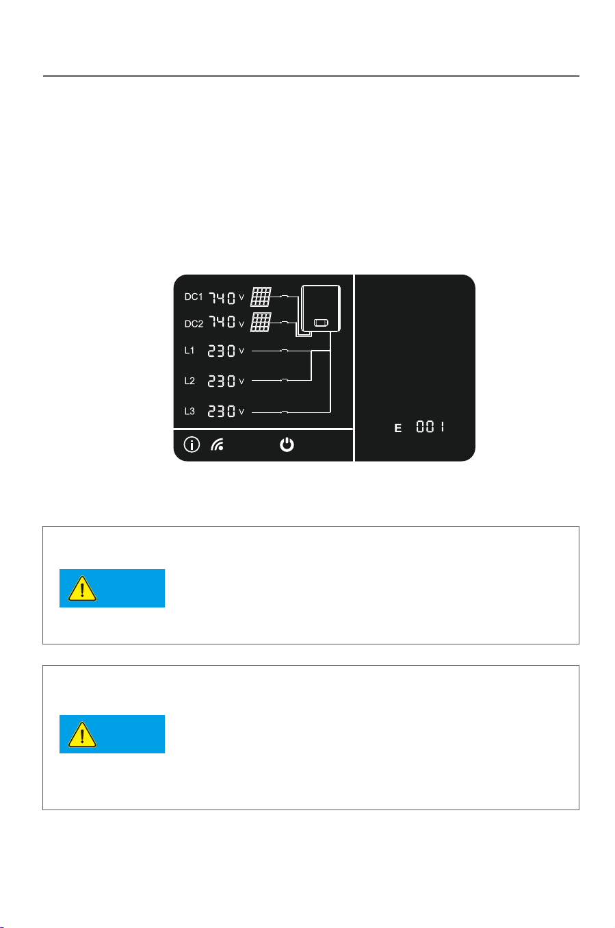
34
5.2.5 Fault mode
Fig. 5-7
Fig. 5-8
35
Human-machine interaction Human-machine interaction
Notice
Notice
LED1
LED2
LED3
5.4 LED blink table
LED
LED1 LED2 LED3 LED1 LED2 LED3
LCD On LCD Off
Mode
Standing-by mode
Ready mode
Power Generating mode
Lightened constantly
Flashing
Protect mode
Fault mode
If any internal fault is detected by the inverter, the inverter will stop power
generating and enter the fault mode, in this case fault indicator on the LCD panel
will show and display the corresponding fault code.
Troubleshooting can be performed by the user according to this code. The
inverter will keep monitoring if the internal fault is removed. It will be reenter the
grid-connect power generating mode if the fault is removed.
5.3 LCD panel power saving mode
The LCD will enter sleep mode if no operation last for 2 minutes , to wake it up
please tap on the shell slightly.
In the morning and evening, the light intensity is weak and
changeful, thus the LCD keep flashing.In order to avoid
the user’s trouble, and the LCD will light up when it enter
into the power generating mode. In other mode, if the user
wants to check the relevant data of the inverter, he can tap
the inverter body and wake up the LCD.
When the inverter enter into the protection and fault mode,
its corresponding protection and fault code may also
appear twice or more. At this time, the protection or fault
code display space below the LCD display screen will
alternately display a variety of protection or fault code
every 2 seconds .
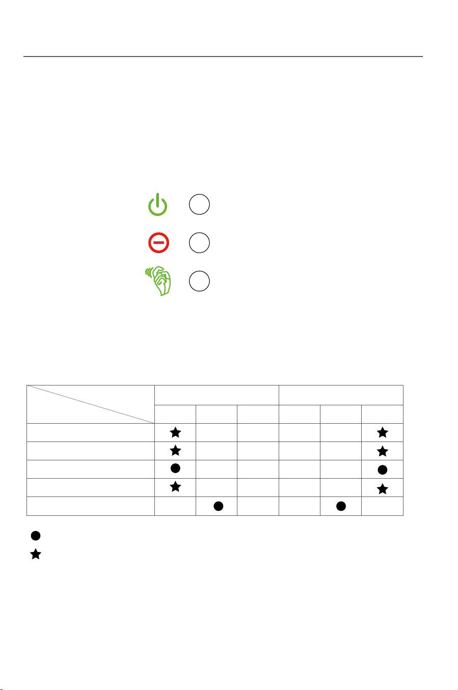

36
6 Troubleshooting and maintenance
6.1 Troubleshooting
Faults mentioned in this part means the inverter enters the
protection state or fault state.
Tip
37
Tab. 6-1: Protection code and solution
Protection description Recommended solution
P009
P010
P008
P007
P006
P005
P004
P003
P002
P001
Displayed code
The leakage
current is too high
The voltage at the grid
side is too high
The voltage at the grid
side is too low
The frequency at the
grid side is too high
The frequency at the
grid side is too low
Islanding protection
The DC voltage is too
low
Output short circuit
Output current DC offset
is too high
Internal synchro
communication fail
Troubleshooting and maintenance Troubleshooting and maintenance
This part introduces the common fault and solving steps, provides
troubleshooting method and skills to the user, and helps the user identify and
solve some common fault of the inverter.
1.Cut off the DC breaker and check if
there is abnormity in the AC side.
2.After the fault is removed, close the
DC breaker and restart the inverter.
3.If the fault occurs repeatedly, please
ask for professional service.
1.Check if the inverter is normally
connected to the grid.
2.Check if the grid voltage and
frequency are complying with the
output scope of the inverter.
3.If the fault above is removed but the
inverter can still not work normally,
please ask for professional service.
The inverter will recover automatically
when the light is sufficient.
The protection state is mostly caused by some external reasons, the inverter
output is not matched with the grid, the grid is power off or the system is not
correctly earthed, and thus the inverter acts to ensure the own safety. The
inverter itself has no defect and can recover from the protection state if the
system is correctly designed and installed.
Sometimes the inverter enters the protection state by the own defect and can
be recovered by resetting or repairing.
The fault state is caused by incorrect design of system, e.g: the DC voltage is
too high, and thus the inverter acts to protect the system safety. The inverter
can be recovered from some faults automatically or by resetting, and some
faults are caused by the own defect of the inverter, and in this case the inverter
cannot be recovered and shall be repaired.
Correctly identifying the fault state of the inverter is helpful for solving the fault,
so please threat as per the following steps:
1) Check if the status displayed on the panel is a protection state or fault state,
and record all error codes.
2) Try the solution listed in Tab.6-1 and 6-2 and meanwhile check as per the
following steps.
●If the voltage at the AC/DC side is normal and if the breaker is switched on?
●If the inverter is installed in a clean , dry and well ventilated place?
●If the cable sectional area satisfies the requirement?
●If the connecting cables is too long?
●If all cables are firmly connected?
●If wiring is reasonable?
●If the safety standard setting is correct?
3) If you
meet any problem that you cannot solve by yourself, please contact
the client service man of Xinqi Power for the optimal solution, please provide
the detailed system installation information, inverter model, serial number and
fault information.
1.Check if the inverter is normally
connected to the grid.
2.Check if the grid voltage and frequency
are complying with the output scope of the
inverter.
3.If the fault above is removed but the
inverter can still not work normally, please
ask for professional service.
1.Switch off the DC breaker and wait 1
minute.
2.Switch on the DC breaker and check if
the inverter can auto reboot.
3.If the fault occurs repeatedly, please ask
for professional service.

38
Tab. 6-2: Fault code and solution
Fault description Recommended solution
E001
E003
Displayed code
39
●Heat radiation
6.2 Daily maintenance
●Cleaning
Troubleshooting and maintenance Troubleshooting and maintenance
1. Switch off the breaker.
2. Check if the resistance between the
+/ - poles of the PV1&PV2 assembly and
the ground is larger than 1MΩ.
3.If the fault above is remove but the
Inverter can still not work normally ,
please ask for professional service.
1. Switch off the DC breaker.
2. Check if DC2 voltage is higher than
1000V
3. If the fault above is removed but the
inverter can still not work normally,
please ask for professional service.
1. Switch off the DC brea
ker.
2. Check if DC1 voltage is higher than
1000V
3. If the fault above is removed but the
inverter can still not work normally,
please ask for professional service.
E002
It is unnecessary to maintain the inverter in normal conditions but it is necessary
to make sure the inverter is not covered by dust.
The inverter can be cleaned by electric compressed air blower, dry soft cloth or
soft brush. Please never clean the inverter by any water, corrosive chemical
agent or cleaning agent.
To protect the normal operation and prolong the service life of the inverter, the
inverter must be installed in a well ventilated space without any air barrier
surrounding the heat radiator at the back of the inverter, and dust or snow must
be removed timely if any.
The insulation
resistance is low
The DC1 voltage is
too high
The DC2 voltage is
too high
Fault description Recommended solution
E004
E005
Displayed code
1. Switch off the DC breaker.
2. Check if t he system is designed
incorrectly(DC1 power too high).
3. If the fault above is removed but the
inverter can still not work normally,
please ask for professional service.
1. Switch off the DC breaker.
2. Check if t he system is designed
incorrectly(DC2 power too high).
3. If the fault above is removed but the
inverter can still not work normally,
please ask for professional service.
The DC1 input
current is too high
The DC2 input
current is too high
P011
P012
P013
P014
P015
Displayed code
Protection description Recomm
ended solution
Phase loss
Over temperature
Bus unbalance
Utility not three phase
Relay open
Check whether all the three phase lines
are connected to the grid.
The inverter will recover automatically
when the temperature gets lower.
The inverter will recover automatically.
Check whether all the three phase lines
are connected to the grid.
The inverter will recover automatically.

40 41
7 Uninstallation
The inverter shall be treated as per the following steps if it is to be replaced or
out of service.
7.1 Uninstalling steps
Fig.7-2
7.2 Packing
7.3 Storing
The inverter must be stored in a dry and clean place of -30℃- +80℃.
7.4 Solution at the termination of service period
Uninstallation Uninstallation
Fig.7-1
At the termination of inverter service period, please send the inverter and
package material to the designated place for electronic waste treatment.
Contact the related authority for treating and recovering if necessary. No
inverter or any part can be disposed or own accord.
Please pack the inverter with the original package if possible. If the original
package is not available, please pack with a carton satisfying the following
requirement.
●Firm enough for 45kg.
●Easy for handing.
●Fully closeable.
1) Switch off the AC breaker.
2) Switch off the DC breaker.
3) Wait for 10min till the inverter is fully discharged.
4) Check by a multimeter and make sure neither the AC side nor the DC side is
electrified.
5) Press the right position of the terminal as Fig.7-1,When you hear a “click”,
then you can pull out the positive and negative DC terminal adaptor as Fig.7-2.

TP12kTL TP15kTL TP17kTL TP20kTL
11500 W
1000 Vd.c.
250 Vd.c.
250...850 Vd.c.
17Ax2
2
13200 W
1000 Vd.c.
250 Vd.c.
250...850 Vd.c.
17Ax2
2
16500 W
1000 Vd.c.
250 Vd.c.
250...850 Vd.c.
20Ax2
2
18500 W
1000 Vd.c.
250 Vd.c.
250...850 Vd.c.
25Ax2
2
22000 W
1000 Vd.c.
250 Vd.c.
250
...850 Vd.c.
25Ax2
2
2 3 3 4 4
10000
11000
1
7
<1.5%
12000
13200
20
15000
16500
2
42 43
50/60 Hz ; 400 Vac
3W/N/PE
45/55 Hz ; 280~490 Vac (Adj)
3
17000
18700
25
20000
22000
30
98.3%
97.8%
98.4%
97.9%
98.5%
98.0%
98.5%
98.1%
98.6%
98.1%
99.9% 99.9% 99.9% 99.9% 99.9%
505/525/245mm
37kg
–25 °C ... +60 °C
IP65
CQC, R-N4105,VDE0126 1 1,AS4777,IEC61727,IEC62116
VDE-A
- -
TP10kTL
Max DC power
Max DC voltage
Min working voltage
MPPT voltage range
Max input current/per string
Number of
Number of input string
MPP trackers
Model
AC nominal power (W)
Max AC apparent power(VA)
Nominal AC output
Max output current(A)
Power factor
Harmonics
Grid type
Efficie
ie
ncy
)( CDtupnI
)( CAtuptuO
AC output range
Max efficiency
Euro efficiency
MPP
DC reverse-polarity protection
DC breaker
DC/AC SPD
Leakage current protection
Insulation Impedance Detection
Residual Current protection
yes
yes
yes
yes
yes
yes
T efficiency
General Data
Dimensions(W/H/D)
Weight
Operating temperature ran
ge
Certificates an
d Approvals
Degree of protection
Cooling concept
Topology
Display
Humidity
Communication RS485 WIFI: /
Warranty:5/10/20 years
0.8leading ...0.8laging
Natural convection
Transformerless
LCD
0-95% ,no condensation
Yes/Opt.
.. tptpse O/O/Y
Safety and protection

4544
9.3 Warranty card
Tab. 9-1: Warranty card
Warranty Card
Customer Information
Name:
Address:
Zip Code: E-mail:
Tel: Fax:
Installation Information
PV module type (parameters): Modules Per String:
Number of Strings: Installation site:
Installation Company: Installer Name:
Inverter detailed Information
Fault Time: Model of Products:
Number of used Products: Number of Fault Products:
Date of Bill of Lading:
Fault Messages:
Brief Fault Description and Photos (Can be attached):
Customer Signature: Date:
For the information on our warranty terms and conditions, please see
our website: http://www.thinkpower.com.cn
9 Quality assurance
9.1 Warranty Policy
For our customers we provide 5 years standard warranty from the date of
installation, you can also upgrade your standard warranty to 10 years. Please
keep the purchasing invoice and trade mark clear for warranty. For more
information, please contact Think Power or your local dealer.
9.2 Exception clause
Any of the following situation will not be covered by our warranty policy:
●Use of undersigned purpose.
●Incorrect system design.
●Incorrect installation.
●Use of any unacceptable in the system.
●Misuse or improper operation.
●Any unauthorized modification or repairing.
●The inverter is damaged by any force majeure(electric shock, fire accident,
earthquack or seaquake, ect).
●Operating beyond safety regulations.
●Damage during transportation.
Quality assurance Quality assurance

46
10 Contact Think Power
Please keep the following contact ways by which you can consult with us for any
product problem.
Add: Room 103, Building No.1, A District, 530 Development Zone, No.100, Jinxiu
Road, Binhu District, Wuxi, Jiangsu Province , China
Tel: 0086-510-85192198
Fax: 0086-510-85192197
Post Code: 214125
E-mail: [email protected] [email protected]
Web: Http://www.thinkpower.com.cn
Contact Think Power

TP10KTL
TP17KTL
TP12KTL
TP20KTL
TP15KTL