Installation manual
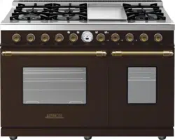
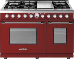
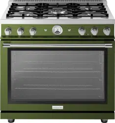
for all 24”, 30”,36” and 48’’ ranges

WARNING:
If the information in this manual is not followed exactly, a fire or explosion may result causing property damage,
personal injury or death.
• Do not store or use gasoline or other ammable vapors and liquids in the vicinity of this or any other appliance.
• WHAT TO DO IF YOU SMELL GAS:
– Do not try to light any appliance.
– Do not touch any electrical switch;
– Do not use any phone in your building.
– Immediately call your gas supplier from a neighbor’s phone. Follow the gas supplier’s instructions.
– If you cannot reach your gas supplier, call the re department.
• Installation and service must be performed by a qualied installer, service agency or the gas supplier.

CONTENTS
Warnings & Important Safety Instructions
Dimensions
Specications Technical data
Clearance Dimensions (Proximity to Cabinets)
Electrical & Gas Requirements
Gas Requirements
General Information
Installation/ Door Removal
Leg Installation/Adjustments/Alignments
Anit-tip Device Installation
Connecting Gas & Electrical
Final Preparation
Performance Checklist
Service & Registration
Warranty U.S.A. & CANADA
Electric diagrams
4
6
14
16
18
19
25
26
27
28
29
26
30
31
32
33
4
|
• Before beginning, please read these instructions completely and
carefully.
• DO NOT remove permanently afxed labels, warnings, or
plates from product.This may void the warranty.
• All local and national codes and ordinances must be observed.
Installation must conform with local codes or in the absence of
codes, the National Fuel Gas Code ANSIZ223.1 INFPA54.
• The installer must leave these instructions with the consumer
who should retain for local inspector’s use and for future
reference.
In Canada: Installation must be in accordance with the current
CAN/CGA B149.1 & 2 Gas Installation codes and/or local codes.
Electrical installation must be in accordance with the current
CSA C22.1 Canadian Electrical Codes Part 1 and/or local codes.
In Massachusetts: All gas products must be installed by a
“Massachusetts” licensed plumber or gastter. A “T” type handle
manual valve must be installed in the gas supply line to the
appliance.
An air curtain or other overhead range hood which operates by
blowing a downward airow onto the range, shall not be used
with a gas range.
Your safety and the safety of others is very important.
We have provided many important safety messages in this manual
and on your appliance. Always read and obey all safety messages.
This is the safety alert symbol.
This symbol alerts you to hazards that can kill or hurt
you and others.
All safety messages will be preceded by the safety alert symbol
and the word“DANGER,” “WARNING” or “CAUTION.”
These words mean:
DANGER
Hazards or unsafe practices which WILL result in severe
personal injury or death.
WARNING
Hazards or unsafe practices which COULD result in
severe personal injury or death.
CAUTION
Hazards or unsafe practices which COULD result in
minor personal injury or property damage.
All safety messages will identify the hazard, tell you how to
reduce the chance of injury, and tell you what can happen if the
instructions are not followed.
A GFI shall be used if required by NFPA-70 (National
Electric Code), federal/state/local laws, or local
ordinances.
• The required use of a GFI is normally related to the location
of a receptacle with respect to any signicant sources of water
or moisture.
• SUPERIORE will NOT warranty any problems resulting from
GFI outlets which are not installed properly or do not meet
the requirements below.
If the use of a GFI is required, it should be:
• Of the receptacle type (breaker type or portable type NOT
recommended)
• Used with permanent wiring only (temporary or portable
wiring NOT recommended)
• On a dedicated circuit (no other receptacles, switches or loads
in the circuit)
• Connected to a standard breaker of appropriate size (GFI
breaker of the same size NOT recommended)
• Rated for Class A (5 mA +/- 1 mA trip current) as per UL 943
standard
• In good condition and free from any loose-tting gaskets (if
applicable in outdoor situations)
• Protected from moisture (water, steam, high humidity) as much
as reasonably possible.
WARNING
To prevent possible damage to cabinets and cabinet nishes, use
only materials and nishes that will not discolor or delaminate
and will withstand temperatures up to 194°F (90°C). Heat
resistant adhesive must be used if the product is to be installed in
laminated cabinetry. Check with your builder or cabinet supplier
to make sure that the materials meet these requirements.
Warnings & Important Safety Instructions
|
5
Warnings & Important Safety Instructions
DANGER
CHEMICAL HAZARD
To avoid risk of property damage and/or
personal injuryor death; this appliance is not
too be used as a heating source.
• Benzene is a chemical which is part of the gas supply to this
cooking product, which is consumed in the ames during
combustion. Exposure to a small amount of benzene is possible
if a gasleak occurs. Formaldehyde and soot are by products of
incomplete combustion.
DANGER
ELECTRICAL SHOCK
HAZARD
To avoid risk of electrical shock, personal injury or death; verify
your appliance has been properly grounded in accordance with
local codes or in absence of codes, with the National Electrical
Code (NEC). ANSI/NFPA 70-latest edition.
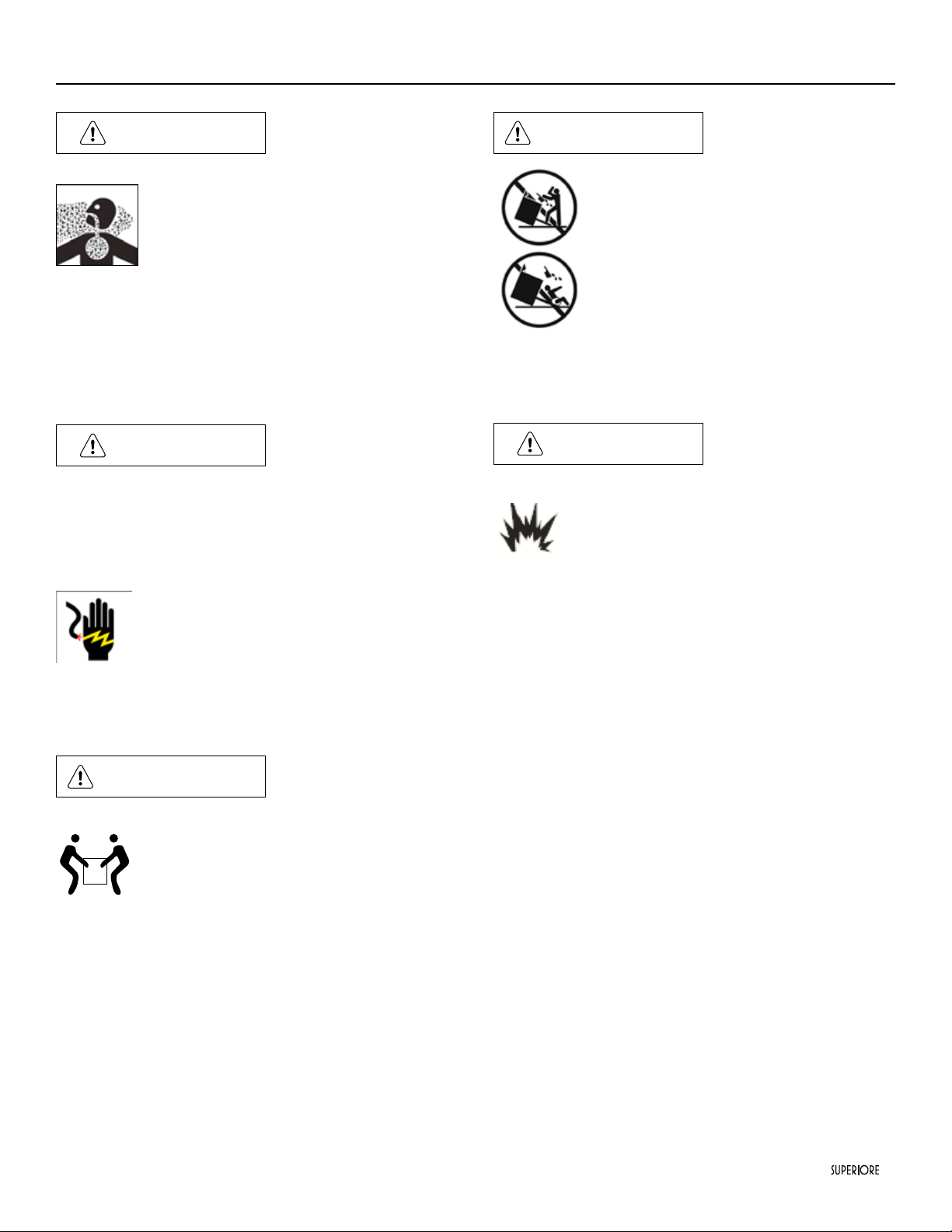
WARNING
MOVING HAZARD
To avoid risk of severe personal injury; this
appliance requires two or more personnel
while handling and moving. Possible use of
appliance moving devices is recommended.
WARNING
TIPPING HAZARD
To reduce the risk of property damage or
personal injury; install anti-tipping device
provided in accordance with the installation
instructions in this document. Device must
be engaged properly to prevent product from
tipping over.
• This range can tip
• Injuries to persons can result
• Install anti-tip device packed with range
• See installation instructions
DANGER
GAS LEAK HAZARD
To avoid risk of personal injury or death; leak
testing of the appliance must be conducted
according to the manufacturer’s instructions.
Before placing appliance in operation, always check for gas leaks
with soapy water solution.
• DO NOT USE AN OPEN FLAME TO CHECK FOR
GAS LEAKS.
6
|
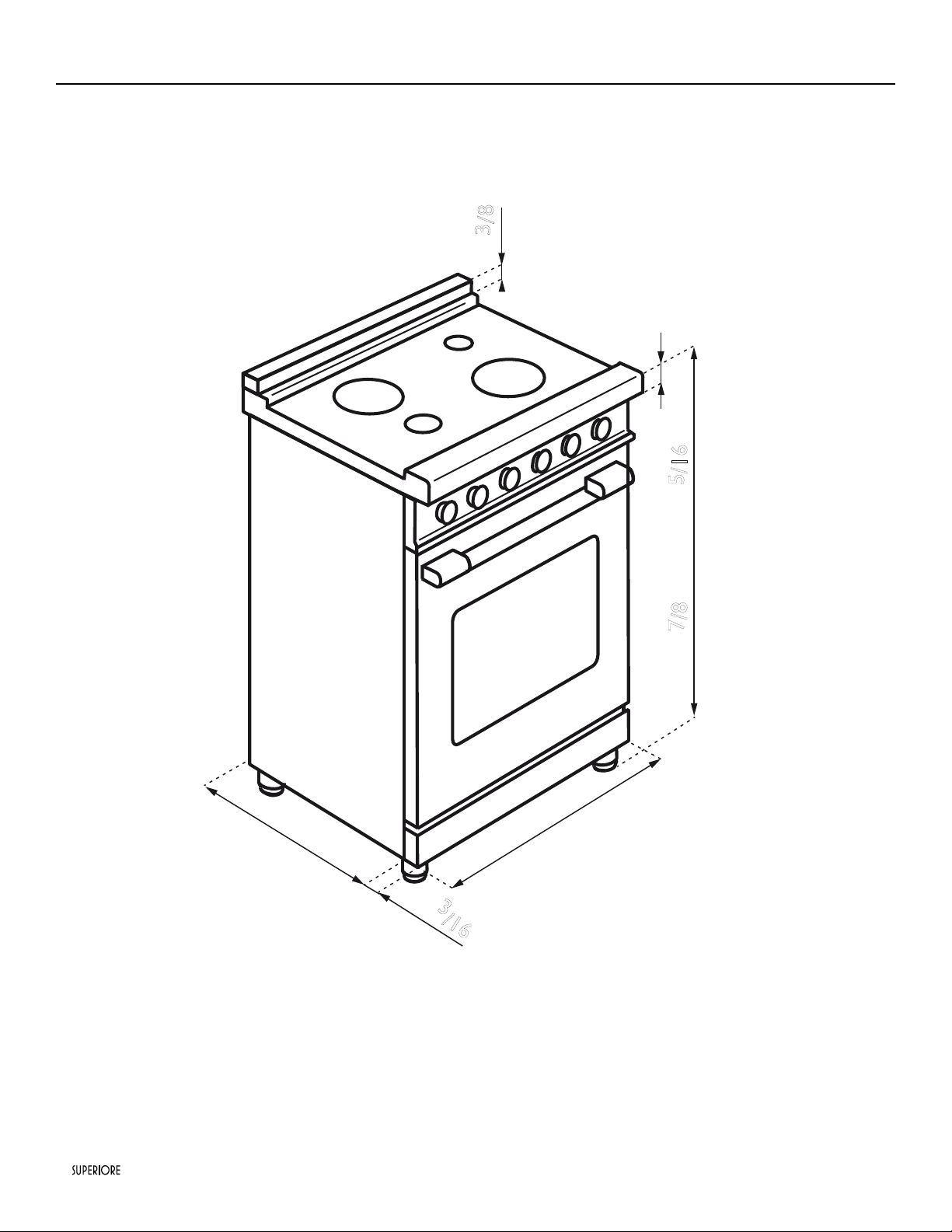
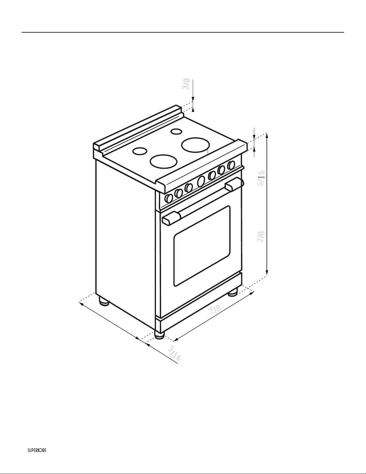
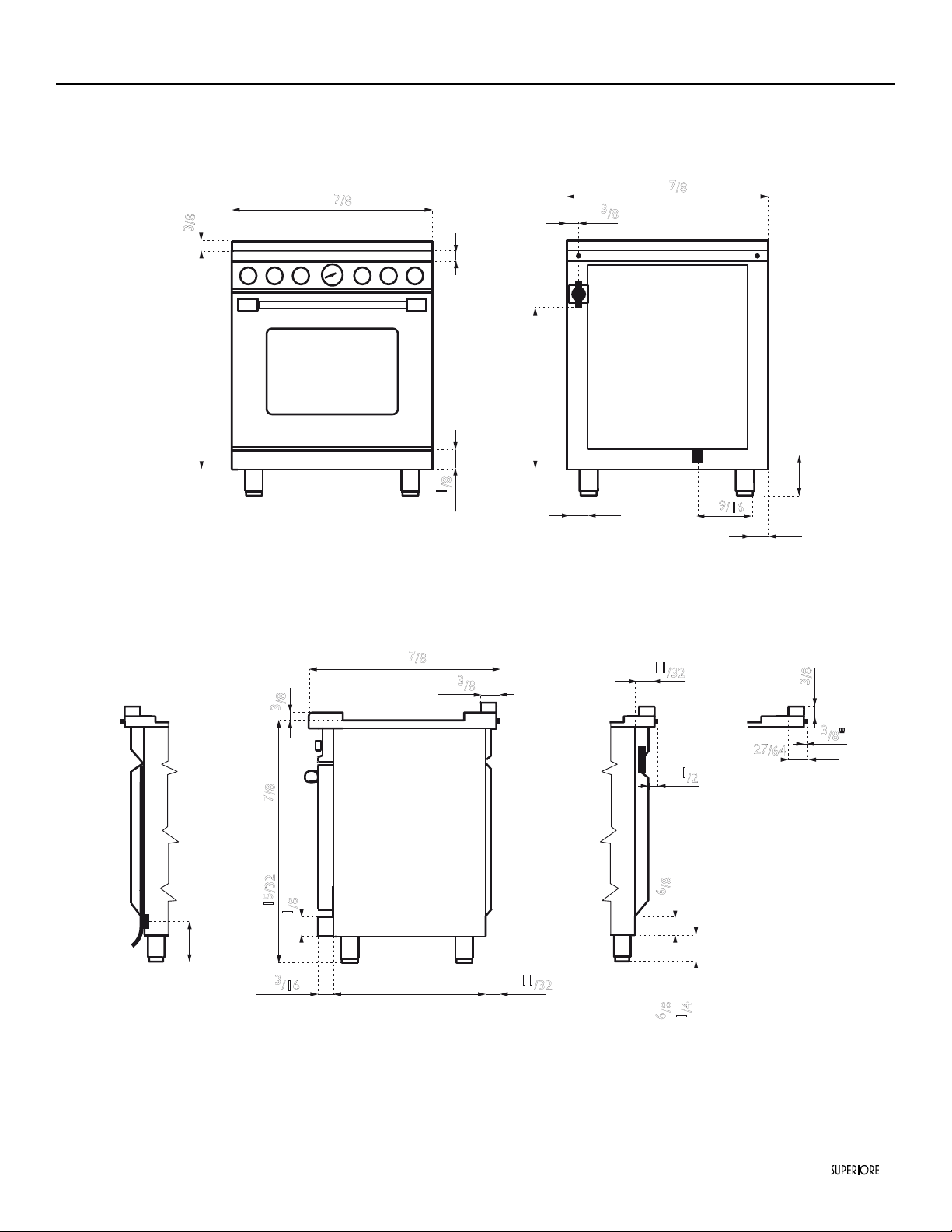
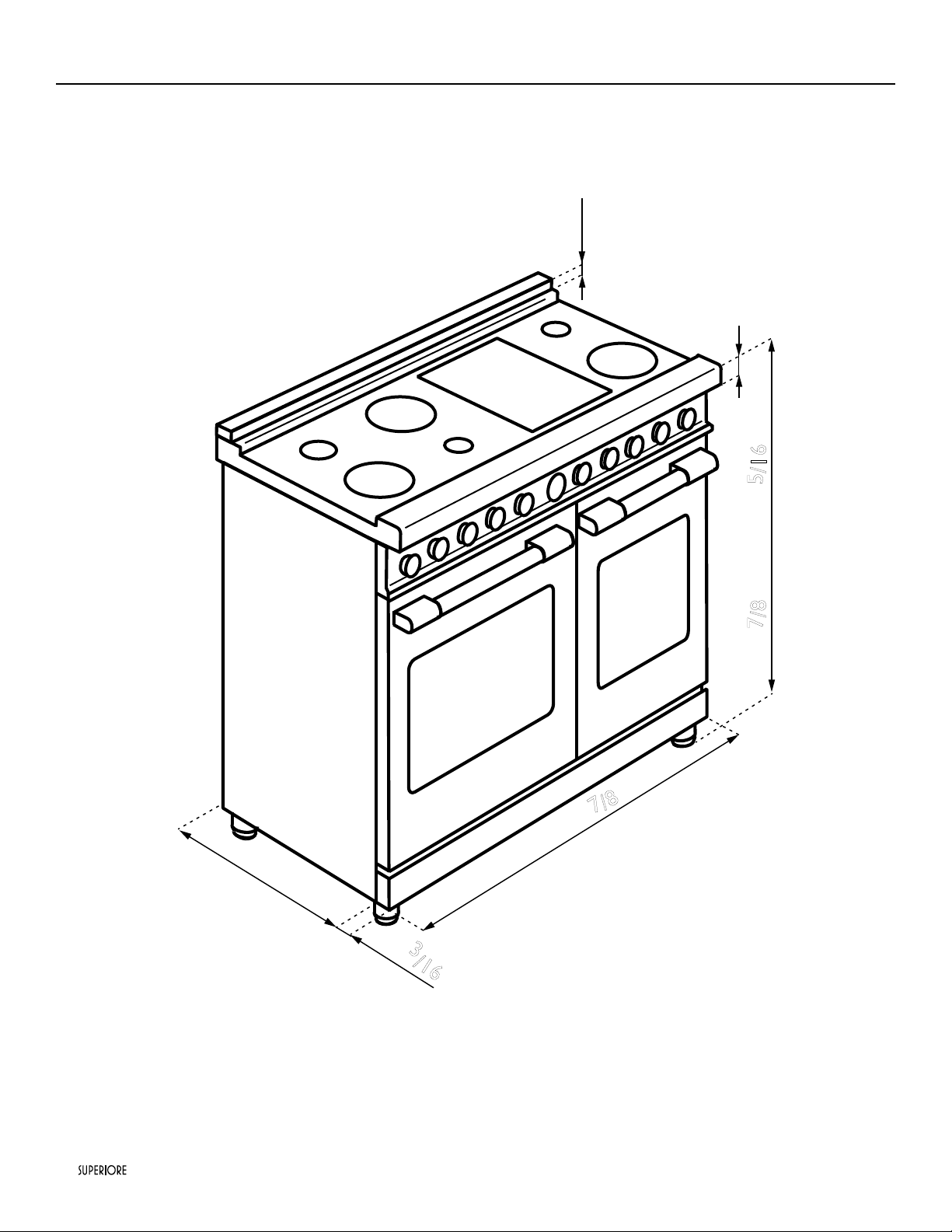
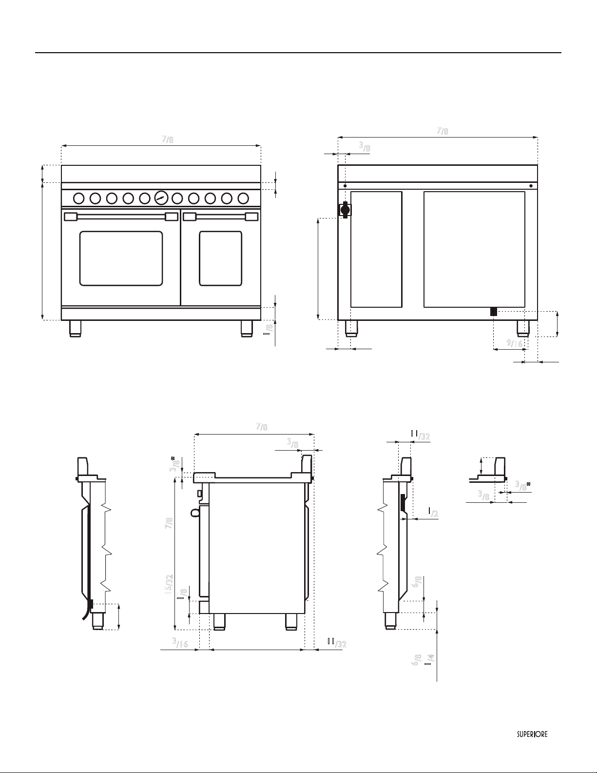
24” SUPERIORE Gas Ranges
Note: Unit shown with island trim.
Note: All gas ranges are equipped with spacer on the back (
25/64
) to prevent over heating of the wall.
23"
7
/
8
23"
2"
2"
25"
2"
2"
1"
1
/2
5"
Gas
33"
1"
11
/32
2"
6
/8
1"
3
/8
23" 7
/8
29"
7
/8
3
/8"
Electricity
2"
1
/8
5"
5"
9
/16
2"
3
/
16
35"
7
/8 min - 37"
5
/16 max
26"
7
/8
2"
3
/8
3
/8"
23"2"
3
/16
2"
1
/8
1"
11
/32
35"
15
/32 min - 36"
7
/8
max
2"
6
/8 min
4"
1
/4
max
1"
3
/8
2"
27
/64
1"
3
/8
1"
3
/8
Dimensions
|
7
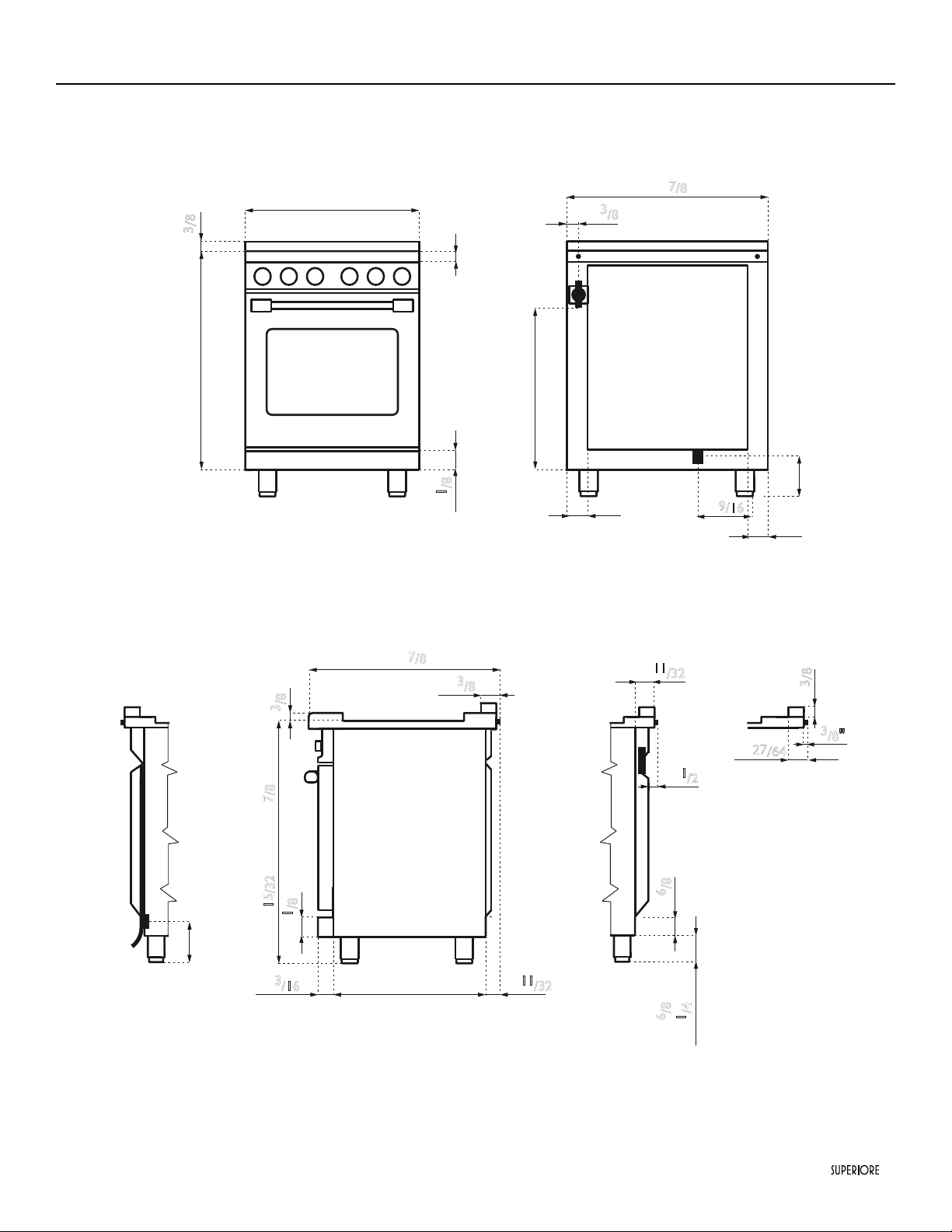
24” SUPERIORE Gas Ranges
23"
7
/
8
23"
2"
2"
25"
2"
2"
1"
1
/2
5"
Gas
33"
1"
11
/32
2"
6
/8
1"
3
/8
23" 7
/8
29"
7
/8
3
/8"
Electricity
2"
1
/8
5"
5"
9
/16
2"
3
/16
35"
7
/8
min - 37"
5
/16 max
26"
7
/8
2"
3
/8
3
/8"
23"2"
3
/16
2"
1
/8
1"
11
/32
35"
15
/32 min - 36"
7
/8 max
2"
6
/8 min
4"
1
/4 max
1"
3
/8
2"
27
/64
1"
3
/8
1"
3
/8
Dimensions
8
|
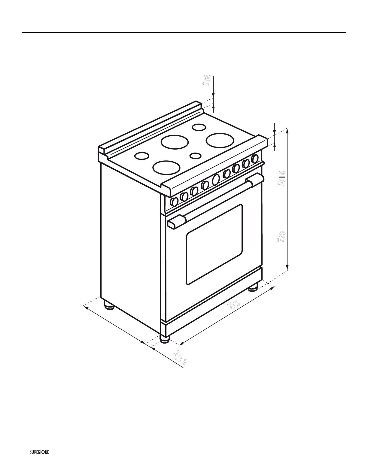
30” SUPERIORE Ranges
Note: Unit shown with island trim.
Note: All gas ranges are equipped with spacer on the back (
25/64
) to prevent over heating of the wall.
29"
7
/
8
23"
2"
2"
25"
2"
2"
1"
1
/2
5"
Gas
33"
1"
11
/32
2"
6
/8
1"
3
/8
29"
7
/8
29"
7
/8
3
/8"
Electricity
2"
1
/8
5"
5"
9
/16
2"
3
/
16
35"
7
/8 min - 37"
5
/16 max
26"
7
/8
2"
3
/8
3
/8"
23"2"
3
/16
2"
1
/8
1"
11
/32
35"
15
/32 min - 36"
7
/8
max
2"
6
/8 min
4"
1
/4
max
1"
3
/8
2"
27
/64
1"
3
/8
1"
3
/8
Dimensions
|
9
30” SUPERIORE Ranges
29"
7
/8
23"
2"
2"
25"
2"
2"
1"
1
/2
5"
Gas
33"
1"
11
/32
2"
6
/8
1"
3
/8
29"
7
/8
29"
7
/8
3
/8"
Electricity
2"
1
/8
5"
5"
9
/16
2"
3
/16
35"
7
/8
min - 37"
5
/16 max
26"
7
/8
2"
3
/8
3
/8"
23"2"
3
/16
2"
1
/8
1"
11
/32
35"
15
/32 min - 36"
7
/8 max
2"
6
/8 min
4"
1
/4 max
1"
3
/8
2"
27
/64
1"
3
/8
1"
3
/8
Dimensions
10
|
Note: Unit shown with island trim.
Note: All gas ranges are equipped with spacer on the back (
25/64
) to prevent over heating of the wall.
35"
7
/8 min - 37"
5
/16 max
35"
7
/
8
23"
2"
2"
33"
35"
7
/8
2"
1
/8
2"
3
/
16
25"
2"
2"
Gas
1"
3
/8
35"
7
/8
Electricity
5"
5"
9
/16
1"
1
/2
5"
1"
11
/32
2"
6
/8
3
/8"
26"
7
/8
2"
3
/8
3
/8"
23"2"
3
/16
2"
1
/8
1"
11
/32
35"
15
/32 min - 36"
7
/8
max
2"
6
/8 min
4"
1
/4
max
1"
3
/8
2"
27
/64
1"
3
/8
1"
3
/8
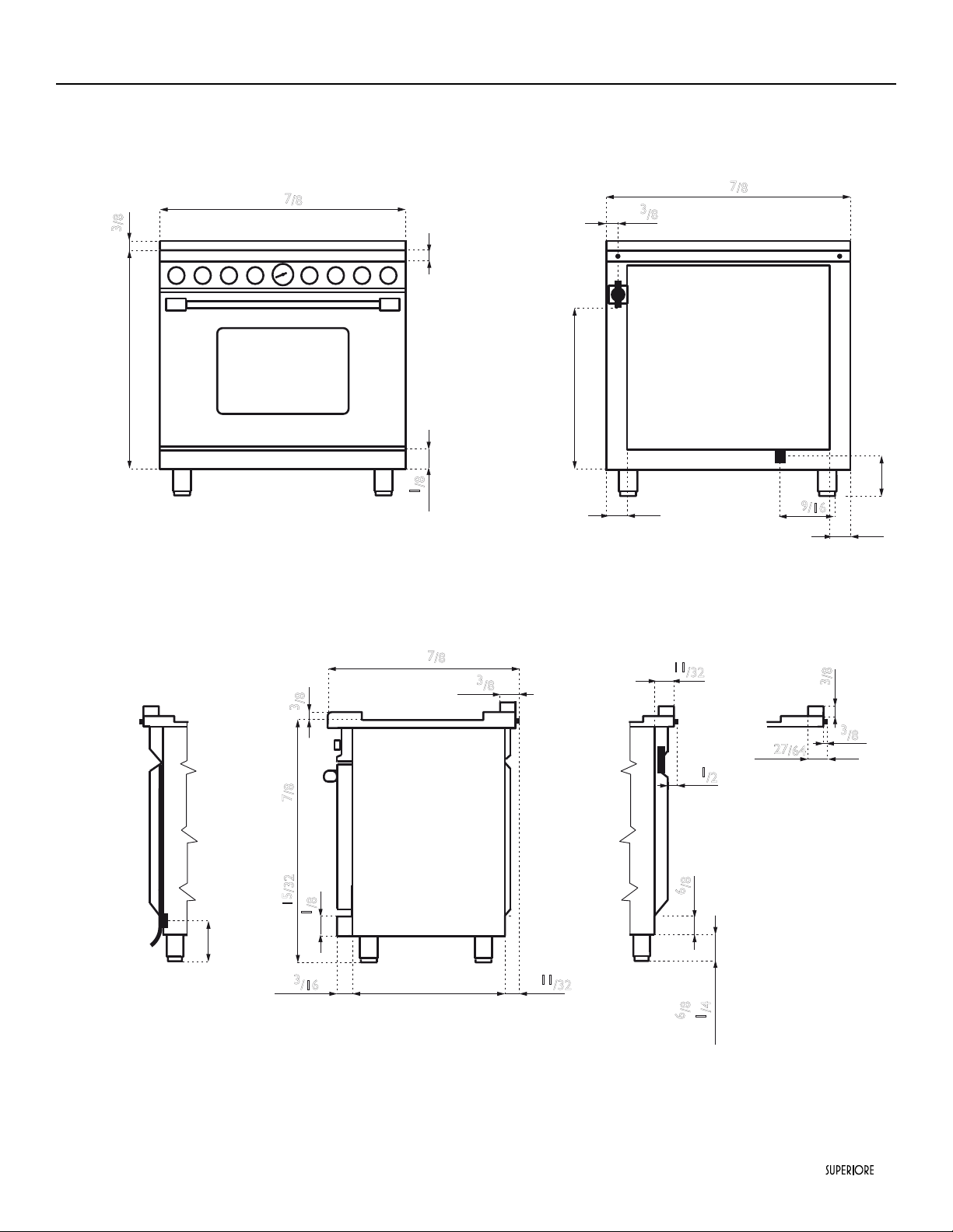
36” SUPERIORE Ranges
Dimensions
|
11
35"
7
/8
min - 37"
5
/16 max
35"
7
/8
23"
2"
2"
33"
35"
7
/8
2"
1
/8
2"
3
/16
25"
2"
2"
Gas
1"
3
/8
35"
7
/8
Electricity
5"
5"
9
/16
1"
1
/2
5"
1"
11
/32
2"
6
/8
3
/8"
26"
7
/8
2"
3
/8
3
/8"
23"2"
3
/16
2"
1
/8
1"
11
/32
35"
15
/32 min - 36"
7
/8 max
2"
6
/8 min
4"
1
/4 max
1"
3
/8
2"
27
/64
1"
3
/8
1"
3
/8
36” SUPERIORE Ranges
Dimensions
12
|
48” SUPERIORE Ranges
Note: Unit shown with island trim.
Note: All gas ranges are equipped with spacer on the back (
25/64
) to prevent over heating of the wall.
Dimensions
Note: Unit shown with island trim.
Note: All gas ranges are equipped with spacer on the back (
25/64
) to prevent over heating of the wall.
1"
47"
7
/8
23"
2"
2"
3
/16
35"
7
/8 min - 37"
5
/16 max
3
/8
|
13
48” SUPERIORE Ranges
Dimensions
2"
4"33"
47"
7
/8
2"
1
/8
25"
2"
2"
Gas
1"
3
/8
47"
7
/8
Electricity
5"
5"
9
/16
1"
1
/2
5"
1"
11
/32
2"
6
/8
3
/8"
2"
3
/8
4"
26"
7
/8
2"
3
/8
3
/8"
23"2"
3
/16
2"
1
/8
1"
11
/32
35"
15
/32 min - 36"
7
/8 max
2"
6
/8 min
4"
1
/4 max
14
|
Burners - injectors and volume, range 30‘‘ (mod. R...301...)
Natural 4’’ LP/Propane 11’’ By-pass
Inj. W BTU/h Inj. W BTU/h
Ø
W BTU/h
Medium burners 117
-
6500 70
-
6500 34
-
1300
Large burner 155
-
11000 93
-
11000 44
-
2700
Power burner
Ext. ring
Int. ring
137 (2)
80
-
18000
82 (2)
50
-
18000 65
-
4700
Power burner
with simmer
Ext. ring
Int. ring
137 (2)
80
-
18000
82 (2)
50
-
18000
60
27
-
4700
Total gas power (all gas
ranges)
67500 -
Total gas power (dual fuel
s.c. ranges)
53500 -
Oven
-all gas ranges
180
-
14000 108
-
14000 52
-
3000
Oven-dual fuel s.c. ranges -
5550 W | 23 A
- -
5550 W | 23 A
- -
5550 W | 23 A
-
Broil-all gas ranges
135
-
8000 82
-
8000 - - -
Feeding 120 V 60 Hz 130 W
Feeding-dual fuel s.c. ranges
120 V/240 60 Hz
Interior dimensions 24
13/64
x
19
57/64
x
20
31/64
(*) Only on mod. ...361
(**) 2 burners on mod. ...361... ; 1 burner on mod. ...362...
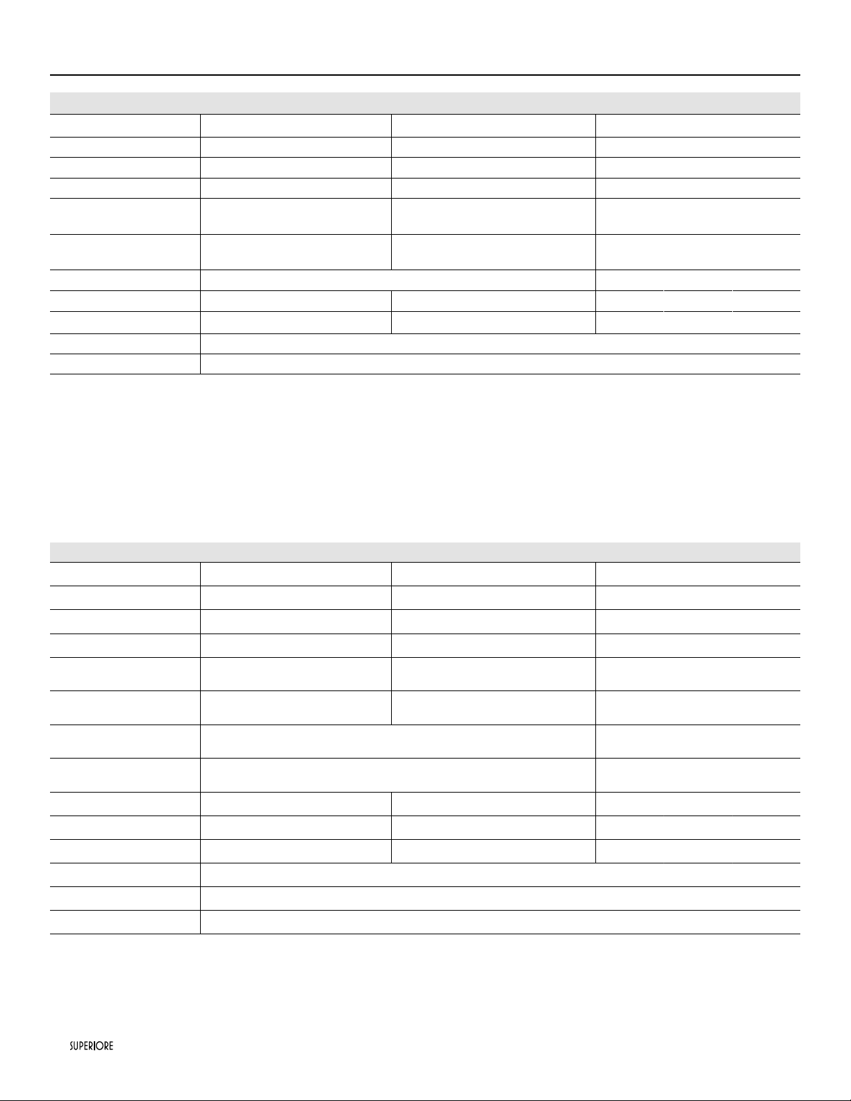
Specifications Technical data
Burners - injectors and volume, range 24‘‘ (mod. R...241...)
Natural 4’’ LP/Propane 11’’ By-pass
Inj. W BTU/h Inj. W BTU/h
Ø
W BTU/h
Medium burners 117 - 6500 70 - 6500 34 - 1300
Large burner 155 - 11000 93 - 11000 44 - 2700
Power burner
Ext. ring
Int. ring
137 (2)
80
- 18000
82 (2)
50
- 18000 65 - 4700
Power burner
with simmer
Ext. ring
Int. ring
137 (2)
80
- 18000
82 (2)
50
- 18000
60
27
- 4700
Total gas power 66.500 -
Oven-all gas ranges 180 - 13000 108 - 13000 52 - 3000
Broil-all gas ranges 120 - 6300 73 - 6300 - - -
Feeding 120 V 60 Hz 130 W
Interior dimensions 18
13/16
x
19
57/64
x
20
31/64
|
15
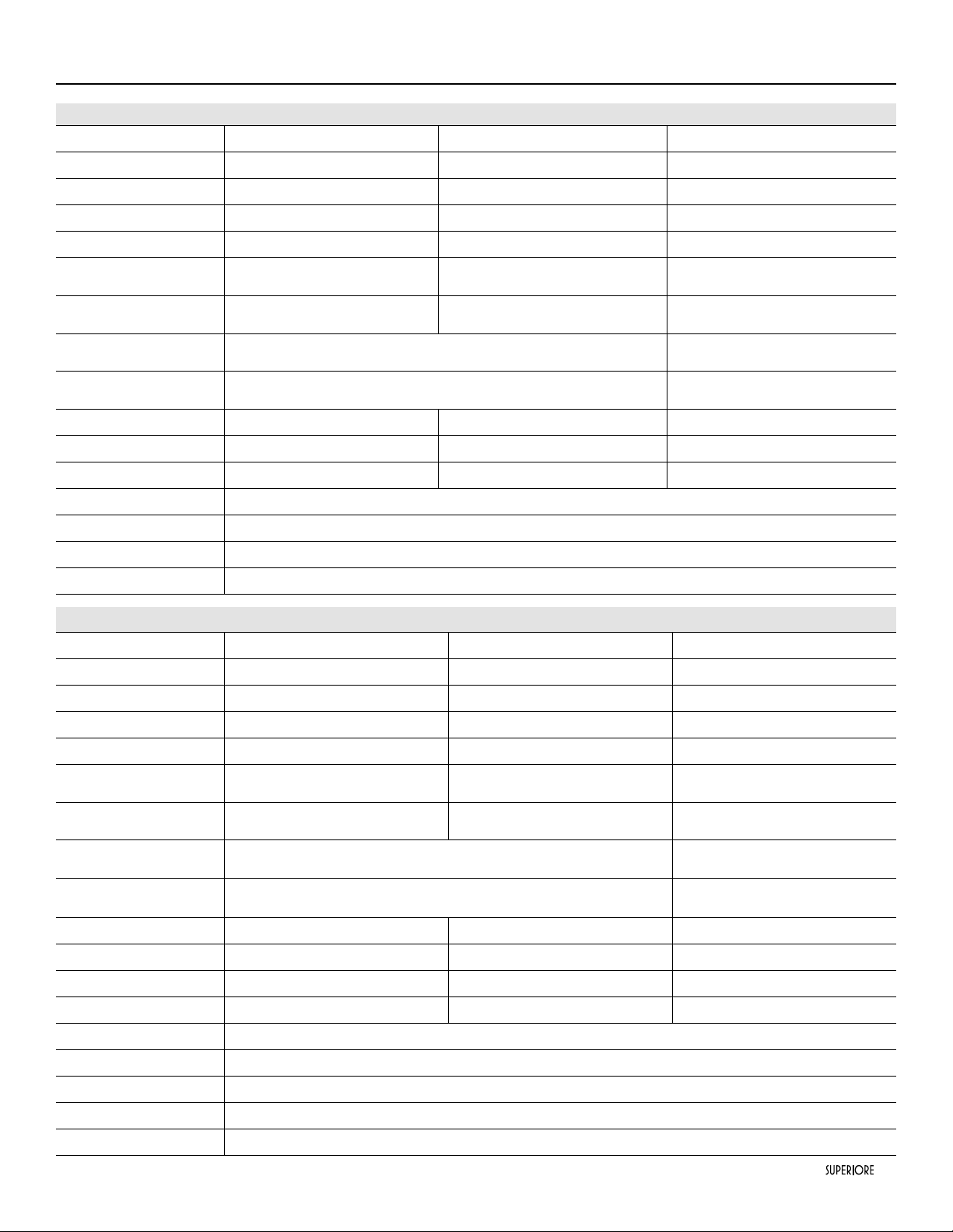
Burners - injectors and volume, ranges 36‘‘(mod. R...361... and R...362...)
Natural 4’’ LP/Propane 11’’ By-pass
Inj. W BTU/h Inj. W BTU/h
Ø
W BTU/h
Small burner (*) 92
-
3600 56
-
3600 28
-
1100
Medium burner (**) 117
-
6500 70
-
6500 34
-
1300
Large burner 155
-
11000 93
-
11000 44
-
2700
Power burner
Ext. ring
Int. ring
137 (2)
80
-
18000
82 (2)
50
-
18000 65
-
4700
Power burner
with simmer
Ext. ring
Int. ring
137 (2)
80
-
18000
82 (2)
50
-
18000
60
27
-
4700
Total gas power (all gas
ranges)
69500 (mod. ...362) and 79600 (mod. ...361...) -
Total gas power (d.f. s.c.
ranges)
53500(mod. ...362) and 63600 (mod. ...361...) -
Oven
-all gas ranges
200
-
16000 115
-
16000 65
-
4400
Oven-dual fuel s.c. ranges -
6150 W | 26 A
- -
6150 W | 26 A
- -
6150 W | 26 A
-
Broil-all gas ranges
155
-
11000 92
-
11000 - - -
Electric griddle 1150 W 120 V
Feeding-all gas ranges
120 V 60 Hz 170 W (mod...361...) or 1320 W (mod....362...)
Feeding-dual fuel s.c. ranges
120 V/240 60 Hz
Interior dimensions 28
3/4
x
19
57/64
x
20
31/64
Specifications Technical data
Burners - injectors and volume Range Mod. R...482...
Methane 4’’ LPG 10’’ By-pass
Burners
Inj. W BTU/h Inj. W BTU/h
Ø
W BTU/h
Small burner 92
-
3600 56
-
3600 28
-
1100
Medium burner 117
-
6500 70
-
6500 34
-
1300
Large burner 155
-
11000 93
-
11000 44
-
2700
Power burner
Ext. ring
Int. ring
137 (2)
80
-
18000
82 (2)
50
-
18000 65
-
4700
Power burner
with simmer
Ext. ring
Int. ring
137 (2)
80
-
18000
82 (2)
50
-
18000
60
27
-
4700
Total gas power (all gas
ranges)
86100 -
Total gas power (dual fuel
self_clean ranges)
63600 -
Oven 48” left cavity all gas 180
-
14000 108
-
14000 52
-
3000
Broil
48” left cavity all gas
135
-
8000 82
-
8000 - - -
Oven 48” right cavity all gas 135
-
8500 80
-
8500 52
-
3000
Ovens-dual fuel s.c. ranges -
9060 W|43 A
- -
9060 W|43 A
- -
9060 W|43 A
-
Electric griddle 1150 W
Feeding-all gas ranges
120 V 60 Hz 1350W (12 A)
or 9060 W (mod....RN482... RD482...)
Feeding-dual fuel s.c. ranges
120 V/240 60 Hz
Overlay cavity volume 5.7 main 3.0 aux
Interior dimensions m. 24
13/64
x
19
57/64
x
20
31/64
/ a. 9
17/64
x
19
35/64
x
20
31/64
16
|
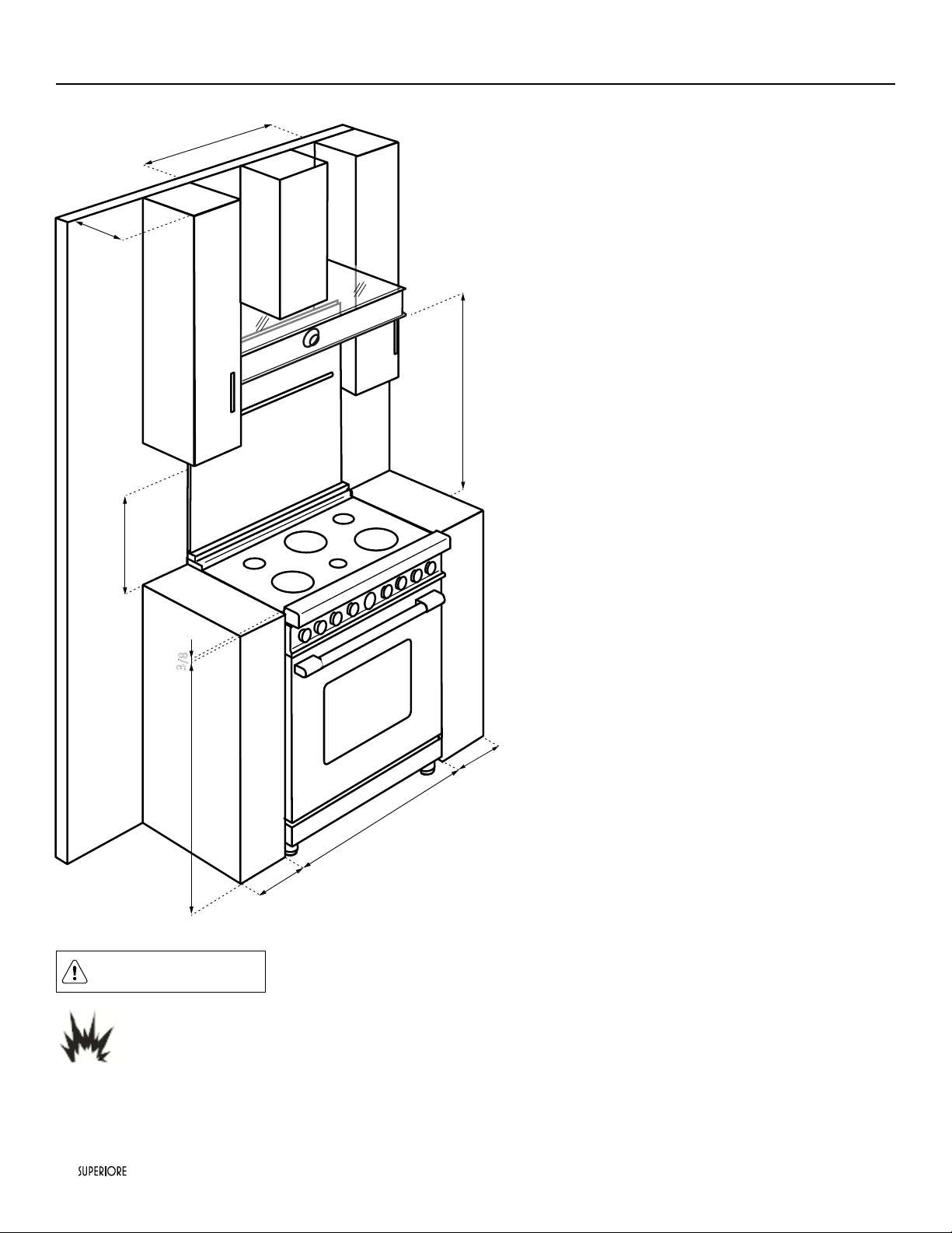
Clearance Dimensions 24’’/30’’/36’’/48’’
• This range may be installed directly adjacent to existing 36”
(91.4 cm) high base cabinets.
IMPORTANT: The side trim MUST be 3/8” (0.95 cm)
above the adjacent base cabinet countertop. This can be
accomplished by raising the unit adjusting the legs.
• The range CANNOT be installed directly adjacent to
sidewalls, tall cabinets, tall appliances, or other side
vertical surfaces above 36”(91.4 cm) high. There must be a
minimum of 6” (15.2 cm) side clearance from the range to
such combustible surfaces above the 36” (91.4 cm) counter
height.
• Within the 6” (15.2 cm) side clearance to combustible
vertical surfaces above 36” (91.4 cm), the maximum wall
cabinet depth must be 13” (33.0 cm) and wall cabinets
within this 6” (15.2 cm) side clearance must be 18” (45.7
cm) above the 36” (91.4 cm) high countertop.
• Wall cabinets above the range must be a minimum of 42”
(106.7 cm) above the range cooking surface for the full
width of the range. This minimum height requirement does
not apply if a range hood is installed over the cooking
surface.
CAUTION
Burn hazard
To avoid risk of personal injury; the use of cabinets for storage above the appliance may resultin a potential burn hazard.
Combustible items may ignite, metallic items may become hot and cause burns. If a cabinet storage is to be provided the risk
can be reduced by installing a range hood that projects horizontally a minimum 5” (12.7 cm) beyond the bottom of cabinets.
Note: If a range hood is installed, wall cabinets above the
range have a different minimum clearance height.
36’’ 30’’ 24’’
min 6"
min 6"
36"
13"
min 18"
3
/8"
36’’ 30’’ 24’’
min 30"
|
17
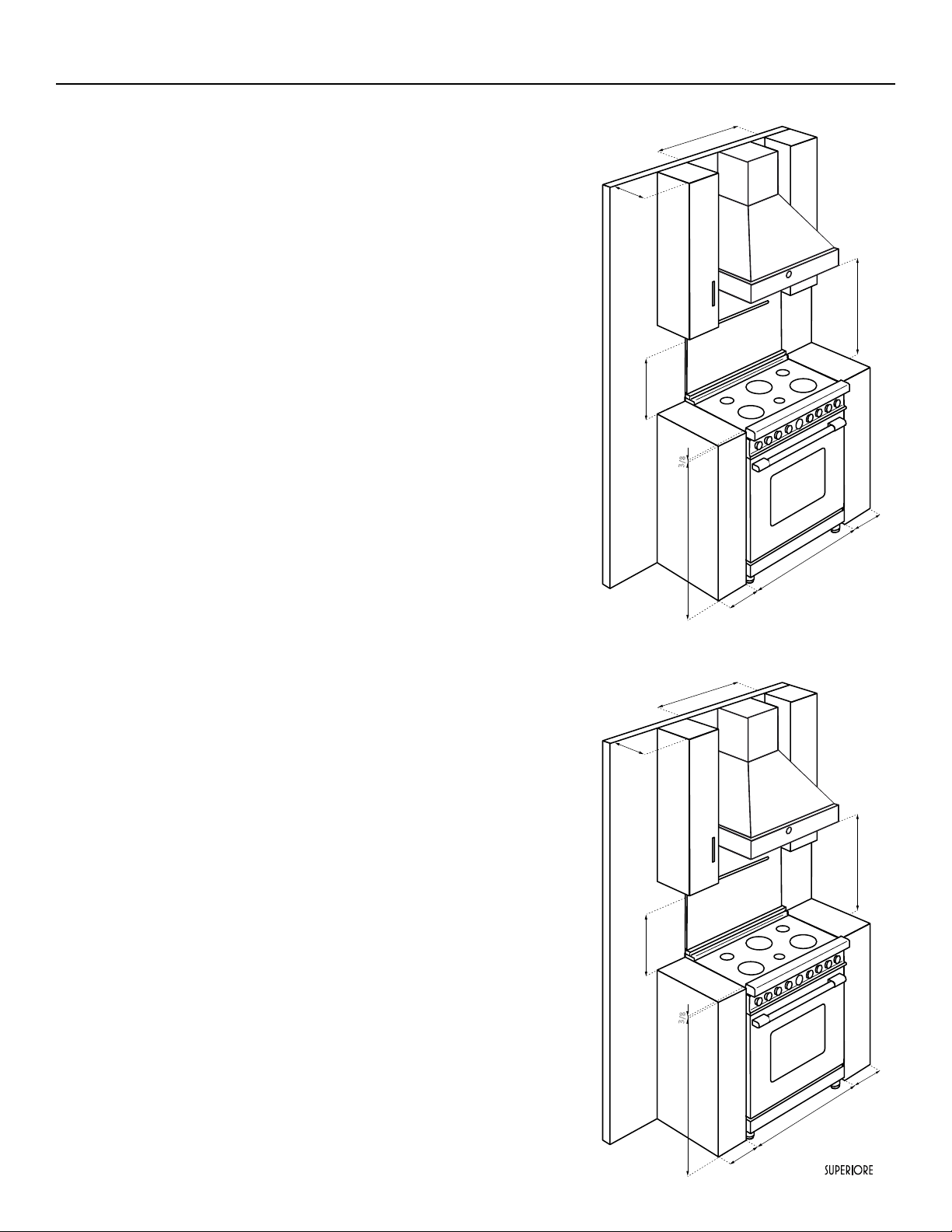
Clearance Dimensions
The bottom of a standard hood should be 30” (76.2 cm) min. to 36”
(91.4 cm) max to above the countertop. This would typically result in
the bottom of the hood being 66” (167.6 cm) to 72” (182.9 cm) above
the oor. Refer to the range hood installation instructions for additional
information. These dimensions provide for safe and efcient operation
of the hood.
Important: There must be a minimum of 6” (15.2 cm) clearance from
rear of range to a combustible wall. Clearances from non-combustible
materials are not part of the ANSI Z21. 1 scope and are not certied by
CSA. Clearances to non-combustible materials must be approved by the
authority having jurisdiction.
36’’ 30’’ 24’’
min 6
"
min 6"
36"
13"
min 18"
3
/8"
36’’ 30’’ 24’’
min 30"
36’’ 30’’ 24’’
min 6
"
min 6"
36"
13"
min 18"
3
/8"
36’’ 30’’ 24’’
min 30"
18
|
Electrical & Gas Requirements
Electrical Requirements
Check your national and local codes regarding this unit. This range requires120VAC/60 Hz; 4 ft. (121.9 cm), 3-wire cord with grounded
3-prong plug attached to unit. See “Electrical Connection” section for grounding instructions. Must be fused seperately from any other
circuit.
WARNING
ELECTRICAL SHOCK HAZARD
To avoid the risk of electrical shock, personal injury or death; verify electrical power is turned off at the breaker box and
gas supply is turned off until the range is installed and ready to operate, installation by an authorized installer only.
Gas Connection
The appliance must be disconnected from the gas supply piping system during any pressure testing of that system.
The gas supply (service) line must be the same size or greater than the inlet line of the appliance. This range uses a 1/2” (1.3 cm) IDNPT
(Sch40) inlet. Sealant on all pipe joints must be resistive to LP gas.
The range is designed specically for natural gas or liquid propane (LP) gas. Before beginning installation verify that the model is
compatible with the intended gas supply.
Manual shut-off valve:
This installer-supplied valve must be installed in the gas service line before the appliance in the gas stream and in a location where it
can be reached quickly in the event of an emergency. Any opeing behind the range shall be sealed.
In Massachusetts: A “T” handle type manual valve must be installed in the gas supply line to the appliance.
IMPORTANT: Any conversion required must be performed by your dealer or a qualied licensed plumber or gas service company.
Please provide the service person with this manual before work begins.
Pressure Regulator
• All ranges have a pressure regulator on the incoming service line for safe and efcient operation, since service pressure may uctuate
with local demand.
External regulators are not required on this range since a regulator is supplied with each unit. Under no condition by-pass this
regulator.
• Manifold pressure should be checked with a manometer, natural gas requires 4.0”W.C.P. and LP gas requires 11.0” W.C.P. Incoming
line pressure upstream from the regulator must be 1” W.C.P. higher than the manifold pressure in order to check the regulator. The
regulator used on this range can withstand a maximum input pressure of 1/2” PSI (14.0” W.C.P.). If the line pressure is in excess of
that amount, a step down regulator will be required.
|
19
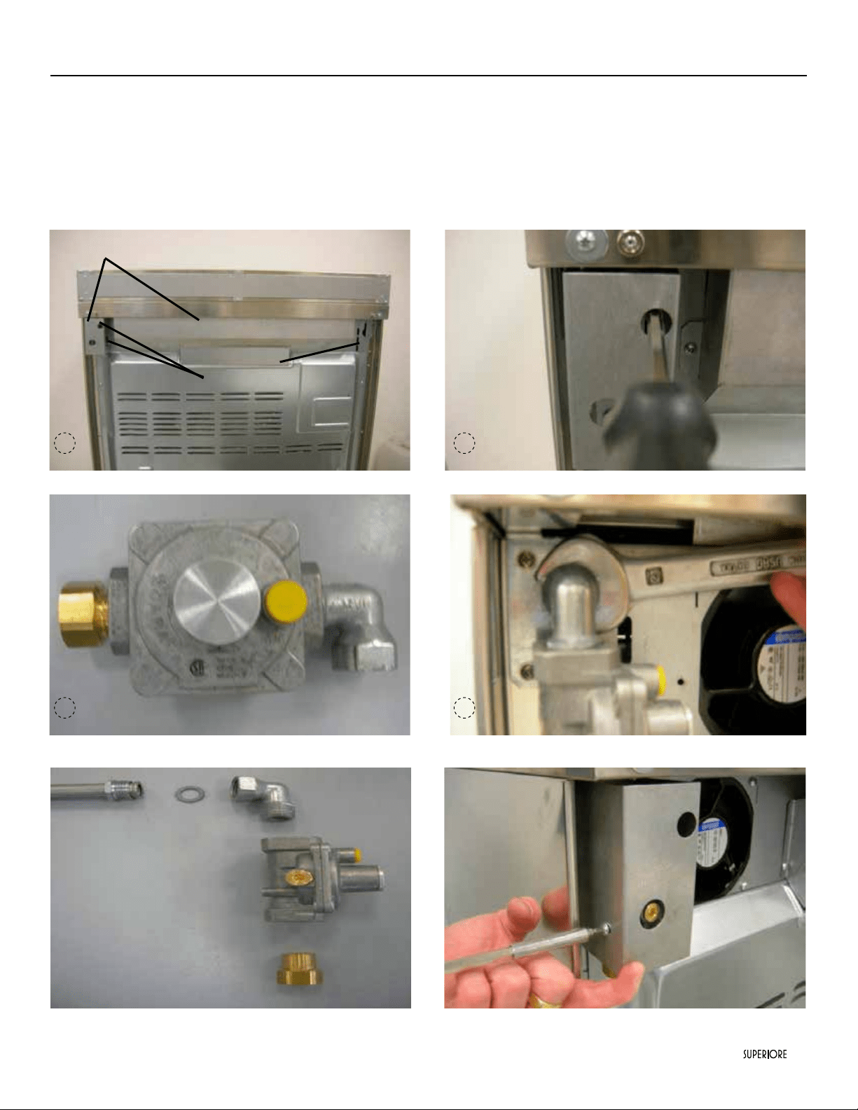
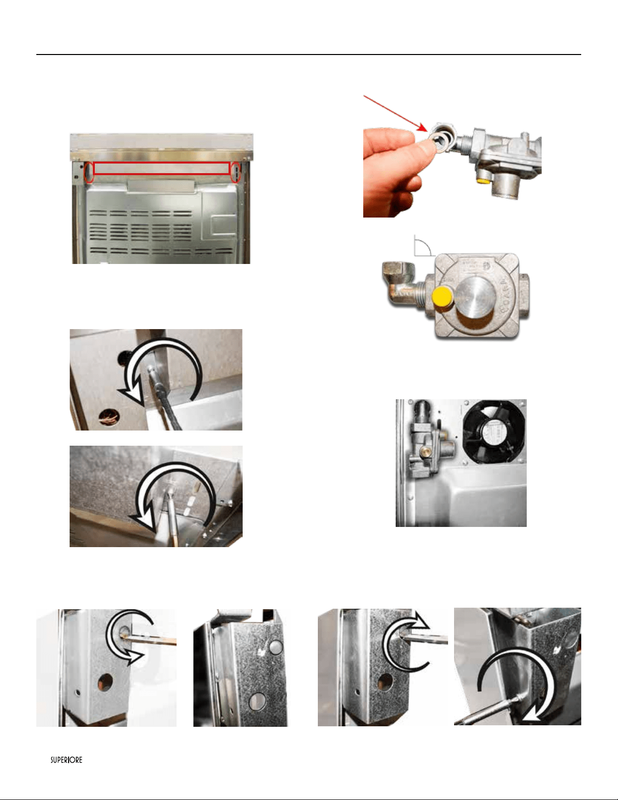
TO INSTALL PRESSURE REGULATOR
1 - Remove the 2 covers on the back by unscrewing the 3 screws indicated at pag 15 step 1 an 2.
2 - Take from the top of packaging the parts shown in the picture below to assemble the pressure regulator.
3 - Screw the assembled pressure regulator on the range like shown on picture below. Pay attention to the vertical alignement of the
same pressure regulator.
4 - Screw the assembled pressure regulator on the range like shown in picture below. Pay attention to the vertical alignement of the
of the pressure regulator.
COVERS
SCREWS
Gas Requirements
1 2
3 4
20
|
REMOVE
Gas Requirements
To perform the following operation is necessary to have eavy
access to the back the range. While performing this plese note
that the range must not be connected to the power and or gas
lines.
1 - Remove the main back cover unscrewing the two screws.
2 - Remove the gas regulator back cover unscrewing the single
screw.
3 - Fit the elbow on the regulator. Put the gasket, in it.
4 - Connect the regulator to the manifold and re-install the main
back cover.
5 - Re-install the gas regulator backcover and x it with two
screws.
|
21
Gas Requirements
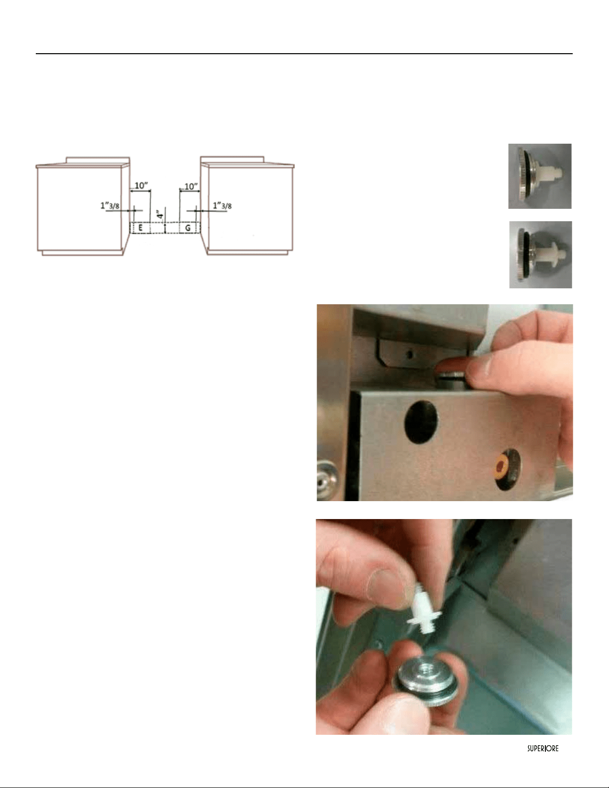
Flexible Connections:
If the unit is to be installed with exible couplings and/or quick-
disconnect ttings, the installer must use a heavy-duty AGA
design-certied exible connector or at least1/2” (1.3 cm)
ID NPT (with suitable strainreliefs) in compliance with ANSI
Z21.41and Z21.69.
G - area for gas connection
E - area for electric connection
In Canada: CAN 1-6, 10-88 metal connectors for gas appliances
and CAN 1-6.9 M79 quick disconnect devices for use with gas
fuel.
In Massachusetts:This appliance must be installed with a 36”
(3-foot) long exible gas connector.
GAS CONVERSION WARNING!
Before carrying out this operation, disconnect the appliance
from gas and electricity. Gas conversion shall be conducted by a
factory-trained professional. Call the customer service hotline
to identify a factory-trained professional near your home. The
gas conversion procedure for this range includes 6 steps:
1. Pressure regulator
2. Surface burners
3. Main oven burner
4. Broiler burner
5. Visual checks prior to closure of oven bottom panel
6. Adjustment of minimum setting.
The conversion is not completed if all 6 steps have not been
concluded properly. Before performing the gas conversion,
locate the package containing the replacement nozzle shipped
with every range.
IMPORTANT:
Each nozzle has a number indicating its ow diameter printed
on the body. Consult the table on “Specications Technical data
“paragraph for matching nozzles to burners. Save the nozzles
removed from the range for future use.
STEP1:PRESSURE REGULATOR
The pressure regulator supplied with the appliance is a
convertible type pressure regulator for use with Natural Gas at a
nominal outlet pressure of 4” w.c. or LP gas at a nominal outlet
pressure of 11” w.c. and it is pre arranged from the factory to
operate with one of these gas/pressure as indicated in the labels
afxed on the appliance, package and Instruction booklet.
To convert the regulator for use with other liquid propane LP
gas:
1. Unscrew by hand the upper cap of
the regulator, remove the white plastic
attachment from the cap, reverse its direction
and screw it again rmly against the cap. The
white plastic attachment must be turned as
follow for NATURAL GAS and as reversed
for LP/PROPANE GAS
2. Screw by hand the metal cap in the original
position on the regulator.
LP/PROPANE GAS
NATURAL GAS
22
|
Gas Requirements
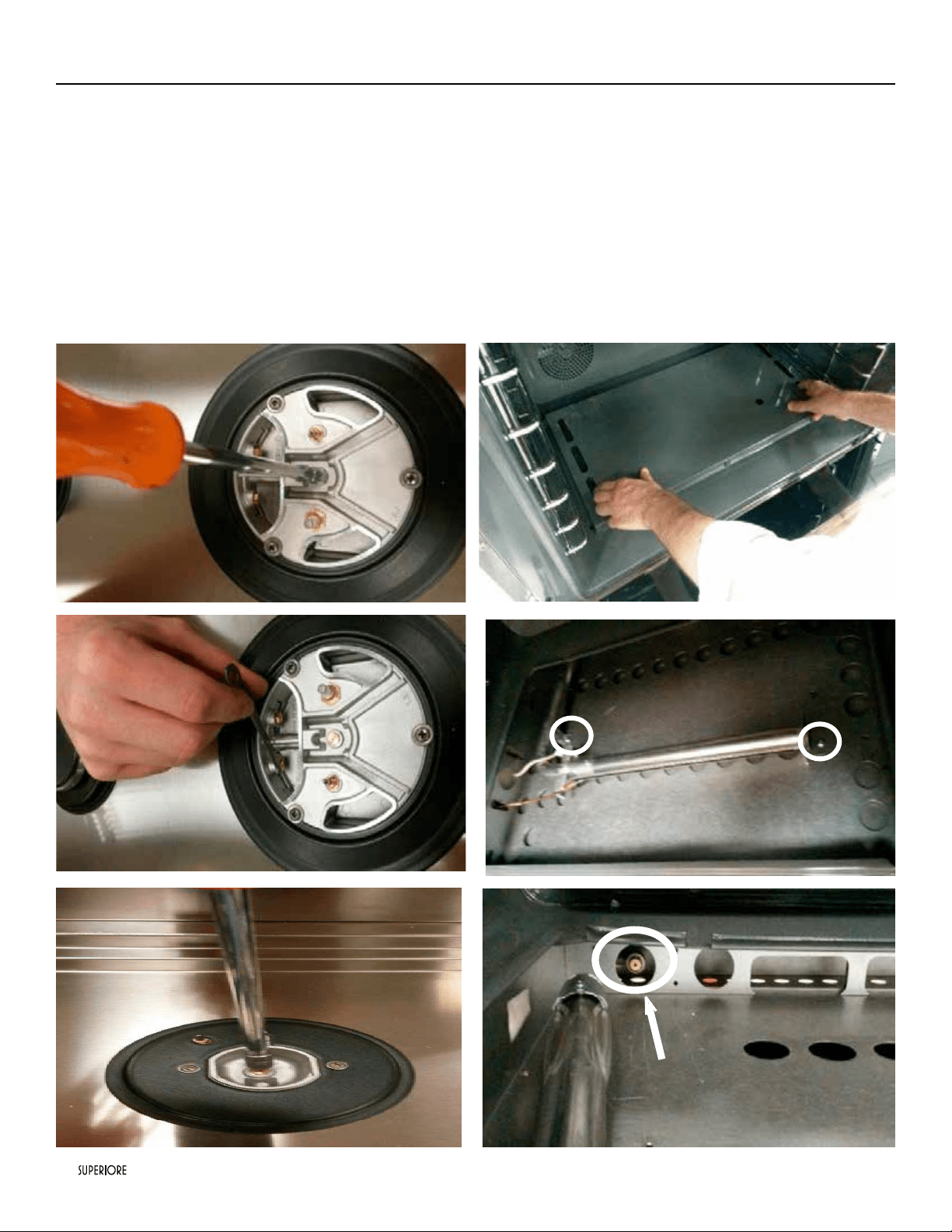
STEP 2: SURFACE BURNERS
To replace the nozzles of the surface burners, lift up the burners
and unscrew the nozzles shipped with the range using a 7 mm
(sochet wrench). Replace nozzles using the conversion set
supplied with the range or by a Tecno authorized parts warehouse.
Each nozzle has a number indicating its ow diameter printed
on the body. Consult the table on “Specications Technical data”
paragraph for matching nozzles to burners.
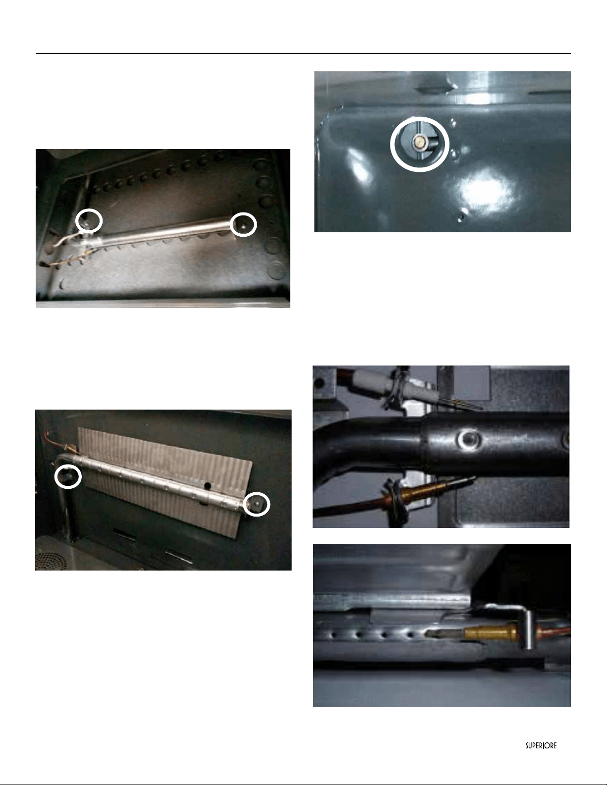
STEP 3 (FOR ALL-GAS RANGES ONLY): MAIN OVEN BURNER
To replace the nozzles of the main oven burner, start by removing
the bottom panel of the oven.
Loose the 2 screw located on the left and right sides of the burner
and the burner from its support.
ATTENTION: pay extra attention to avoid damage to the igniter
and thermocouple.
Unscrew the nozzle located inside the gas tting using a 10 mm or 7
mm socket wrench. (It depends on type of injector).
|
23
Gas Requirements
Replace the nozzle using the conversion set supplied with the range
or by a Tecno authorized parts warehouse. Each nozzle has a number
indicating its ow diameter printed on the body. Consult the table
on “Specications Technical data “ paragraph for matching nozzles
to burners.
Air adjustment is not needed.
STEP 4 (FOR ALL-GAS RANGES ONLY): BROILER BURNER
Loosen the 2 screws on left and right sides and pull out the
burner from its support burner from its support.
ATTENTION: pay extra attention to avoid damage to the
igniter and thermocouple.
Using a 7 mm or 10 mm sochet wrench to unscrew the nozzle.
Replace the nozzle using the conversion set supplied with the
range or by a Tecno authorized parts warehouse. Each nozzle
has a number indicating its ow diameter printed on the body.
Consult the table on “Specications Technical data “ paragraph for
matching nozzles to burners.
ATTENTION: Air adjustment is not needed.
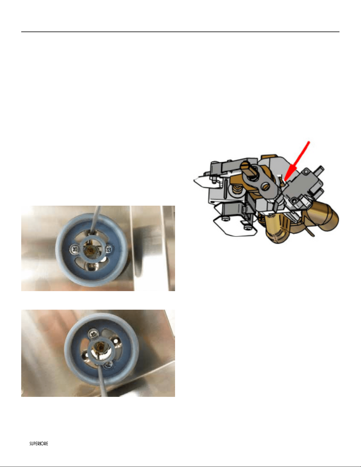
STEP 5 (FOR ALL-GAS RANGES ONLY): VISUAL CHECKS
Before reinstalling the bottom panel, the following visual check
must be performed to ensure that the conversion has been
carried out properly and without damage to other components
of the range.
OVEN IGNITER AND THERMOCOUPLE POSITION
The appropriate gap between the tip of the spark plug or
thermocouple and the burner shall be approximately 1/8’’.
For 24” and 30” range’s
24
|
Gas Requirements
The tip of the spark plug or thermocouple must fully overlap at
least the rst gas emission hole of the burner. After performing
all these visual checks, reinstall the bottom panel of the oven
compartment and proceed to setting the minimum for each
burner.
STEP 6: MINIMUM FLAME ADJUSTMENT
WARNING! These adjustments should be made only for use of
the appliance with natural gas. For use with liquid propane gas,
the By-pass screw must be fully turned in a clockwise direction.
SURFACE BURNERS
1. Light one burner at a time and set the knob to the MINIMUM
position (small ame).
2. Remove the knob.
3. The range is equipped with a safety valve. Using a small size
slotted screwdriver, locate the By-pass screw valve on the
valve body and turn it to the right or left until the burner
ame is adjusted to desired minimum.
4. Make sure that the ame does not go out when switching
quickly from the MAXIMUM to the MINIMUM position.
For surface hob burners
For simmer burners, on the tap in the right
OVEN BURNER
1. Set the oven temperature control knob to the MAXIMUM
setting.
2. Close the oven door and operate the oven for at least 10
minutes.
3. Set the knob to the MINIMUM setting
4. Remove the knob.
5. With a slotted screwdriver turn the choking screw (bypass
screw at the left side of the thermostat bar) and, while
observing the ame at the same time through the bottom
oven porthole, evaluate the consistency of the ame so it
remains on when switching quickly from MINIMUM to
MAXIMUM setting.
|
25
General Information
READ AND FOLLOW ALL WARNING AND CAUTION INFORMATION WHEN INSTALLING THIS APPLIANCE.
• All openings in the wall behind the appliance and in the oor under the appliance must be sealed.
• Do not obstruct the ow of combustion and ventilation air.
CAUTION
Avoid any damage to oven vents.
The vents need to be un obstructed and open to provide proper airow for optimal oven performance.
CAUTION
The cooling fans should be working when the unit is in operation, until the appliance has reduced its external temperatures. If you notice
the cooling fans are not operating or you observe unusual or excessive noise coming from the cooling fans, contact a SUPERIORE
Service Center before continuing operation. Failure to do so can result in damage to the oven or surrounding cabinets.
Moving, Handling and Unpacking
Remove and discard all packing materials, including cardboard and tape on the outside and inside of the range. Remove the burner
grates and styrofoam off the top cooking surface. Be sure to remove the burner caps packaged in styrofoam below the burner grates.
Do not discard the anti-tip metal bracket supplied with the range.This is the anti-tip device and must be installed with the unit. Refer
to“Anti-tip Device Installation” section.
Some stainless steel parts may have a plastic protective wrap which must be peeled off. The interior should be washed thoroughly with
hot, soapy water to remove lm residues and any dust or debris before being used, then rinsed and wiped dry.
Solutions stronger than soap and water are rarely needed.
26
|
Installation/Door removal
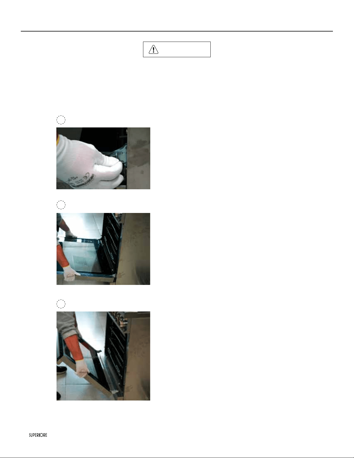
NOTICE
DO NOT use the handle or oven door to lift the oven. DO NOT lift or carry the door by the handle.
Removing the door must be done by your dealer, a qualied licensed plumber, or certied gas installer.
1
2
3
Door Removal
1)- Open the door completely. Place the pins, supplied with
unit, in pin hole. For personal safety, ONLY use pins
supplied with the unit.
2)- Grasp the door as indicated in the photos below and
turn up until you perceive the block.
3)- Lift the door up and extract.
|
27
Superiore ranges must be used only with the legs properly
installed.
Four height adjustable legs, assembled under the bottom
of the range
Four height adjustable legs are delivered with the range in the
polysterene container situated over the appliance.
Before installing the legs, position the appliance near its nal
location as the legs are not suitable for moving the appliance
over long distances.
After unpacking the range, raise it enough to insert the legs in
the appropriate receptacles situated on the lower part of the
appliance. Lower the range gently to keep any undue strain from
legs and mounting hardware. If possible use a pallet or lift jack
instead of tilting the unit.
NOTE: please install the front legs rst, and then the
back legs, to avoid any damage to the unit.
Adjust leg height to the desired level by twisting the inside
portion of the leg assembly until the proper height is reached.
Check with a level that the worktop allignement is perfectly level.
Insert the legs in the appropriate receptacles
Remember that is indicated to set the high corner of range so
that the top of side trim is 3/8” (0.95 cm) above countertop.
(see paragraph “Dimension”)
Leg Installation/Adjustments/Alignment
28
|
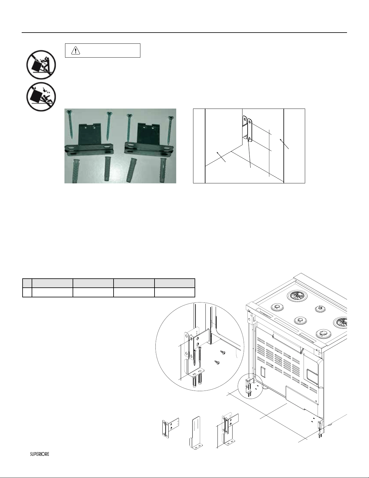
Anti-tip Device Installation
WARNING
TIPPING HAZARD:
To reduce the risk of property damage or personal injury; install anti-tipping device provided in accordance
with the installation instructions in this document.
Device must be engaged properly to prevent product from tipping over.
TIPPING
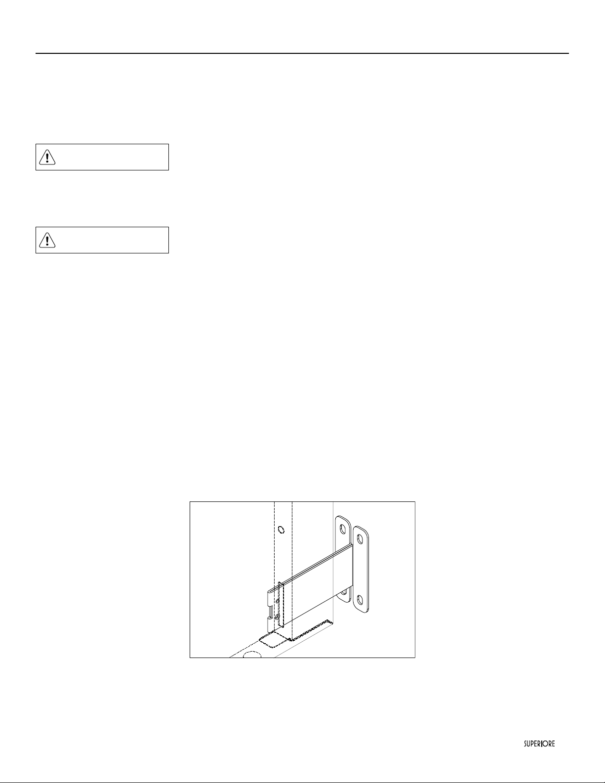
Kit enclosed with the range. Mark and drill
holes where the bracket will be located.
GROUND FIXING BRACKETS
Adjust the range height by regulating the feet , until you reach the desired cooktop height.
Fix the components B to the ground , according to width Y (see below chart).
24’’ 30” 36” 48”
Y
22”
9/16
28”
35/64
34”
17/32
46”
17/32
Insert the component A in the hole in the back of the
cooker and measure the distance X (from the upper
edge of the hole to the ground).
Fix A to B with the screws , keeping the distance X.
Repeat the same sequence on the other side of the
product.
Slide the range towards the wall until the brackets A
are well into the holes in the back of the product.
Measure from oor to the anti-tip bar located
in a slit on the back of the range.
A
X
B
Y
=
=
X
|
29
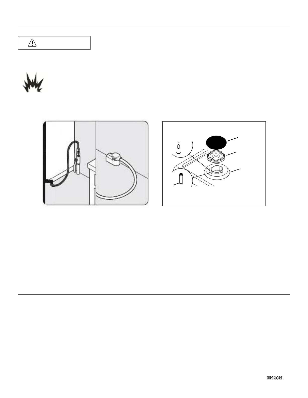
DANGER
GAS LEAK HAZARD
To avoid risk of personal injury or death; leak testing of the appliance must be conducted according to
the manufacturer’s instructions. Before placing appliance in operation, always check for gas leaks with
soapy water solution.
• DO NOT USE AN OPEN FLAME TO CHECK FOR GAS LEAKS.
Connecting Gas & Electric
Connect gas and electrical.
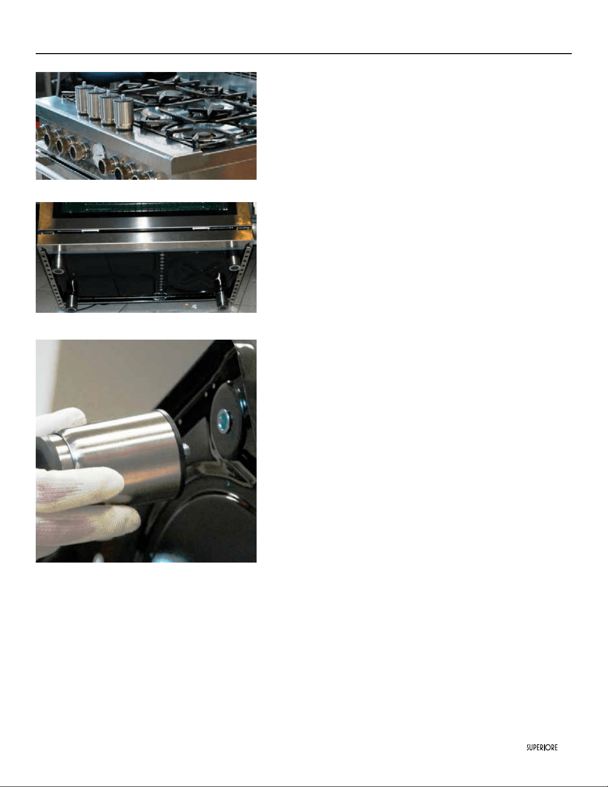
Before placing appliance in operation, always check
for gas leaks. This must be performed by your dealer,
a qualied licensed plumber, or gas service company.
Burner caps are packed in styrofoam top pack with
the grates. Place burner on top of range. Place burner
grate on top of burner cap and grate support.
•All stainless steel body parts should be wiped with hot, soapy water and with a liquid cleaner designed for this material. If buildup
occurs, DO NOT use steel wool, abrasive cloths, cleansers, or powders! If it is necessary to scrape stainless steel to remove encrusted
materials, soak with hot, wet cloths to loosen the material, then use a wool or nylon scraper. DO NOT use a metal knife, spatula, or
any other material tool to scrape stainless steel! Scratches arealmost impossible to remove.
Final Preparation
30
|
A qualied installer should carry out the following checks:
• Check top burner ignition. Push and turn the knob “Full on“ position.
The low ame should light at every port.
• Check oven bake function bake burner on full power.
• Check convection broil function broil burner at full power.
• Check convection fans function convection fans comes on when switch is turned on.
• Convection fans do not operate when broils working.
Performance Checklist
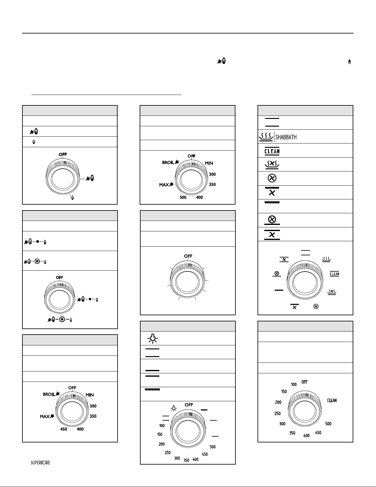
Worktop burner knob
OFF
= Closed position
= “Full on” position (High ame)
= “Reduced rate” position (Low flame)
For all gas ranges only
OFF
= Closed position
from MIN to MAX
(300 - 500 °F)
= Oven temperatures
Broil = Broil
For all gas ranges only - Griddle
OFF
= Closed position
from 1 to 7
positions
= Griddle temperatures
For dual fuel s.c. ranges only
OFF
= Zero position
from MIN
to MAX (100-
500 °F)
= Oven temperatures
CLEAN = Cleaning function
Worktop burner knob + simmer
OFF
= Closed position
=“Full on” position internal ring
= “Full on” position esternal ring
For all gas ranges only
OFF
= Closed position
from MIN
to MAX (300-
450 °F)
= Oven temperatures
Broil = Broil
For dual fuel s.c. ranges only
= Bake
= Warming
= Self cleaning function
= Dehy Drate
=
Convection
= Convection Broil
= Broil
= Turbo
= Convection Bake
For dual fuel sc ranges only - aux oven
= Light
= Bake
= Lower bake
= Upper bake
= Broil

|
31
Only authorized replacement parts may be used in performing service on the appliance. All servicing should be referred to a qualied
technician.
Contact SUPERIORE 1-844-322-2111, for the nearest service parts distributor in your area or write to:
CUSTOMERCARE@TECNOSPA.IT
Record the information indicated below. You will need it if service is ever required. The model and serial number can be found by
looking in the last page of this booklet. A duplicate label is located on the back side of the range.
model number ..........................................................................................................................................................
serial number ............................................................................................................................................................
date of purchase ........................................................................................................................................................
date installed .............................................................................................................................................................
dealer’s name ............................................................................................................................................................
address .......................................................................................................................................................................
These installation instructions should remain with the unit for future reference.
Service & Registration

32
|
WARRANTY U.S.A & CANADA
Please record your model (MOD) and serial number (S/N) below for future reference. For your convenience, a label containing this
information is supplied with this booklet. When writing or calling about a service problem, please include the following information:
- your name, address and telephone number
- appliance model and serial number
- name and address of your dealer
- a clear description of the problem you are having
- proof of purchase (sales receipt)
MOD:_______________________
S/N:________________________
TECNOGAS SUPERIORE WARRANTY TWO YEARS PARTS AND LABOR
For two year from the date of the original purchase, SUPERIORE will repair or replace (at its option) any part of the range which
fails due to a defect in materials or workmanship. During this warranty, SUPERIORE will provide, free of charge, all labor and in-home
service to repair or replace the defective part. This warranty is extended to the original purchaser and any succeeding owner with
proper documentation of ownership for products purchased for residential use within the United States of America.
EXCLUSIONS
This warranty does not cover any defect or damage, which is not direct fault of SUPERIORE; this includes, but is not limited to:
1) Service trips to your home to instruct you how to use the product.
2) Service trips to your home, during which no fault is found.
3) Damages occurred during transit, handling and/or installation of the product.
4) Damages occurred in case the product has not been installed, duly following the manufacturer’s installation instructions, as well as
any local code or regulation.
5) Damages due to failure in following the manufacturer’s recommended care, cleaning and maintenance instructions; in particular,
damages to the oven and/or the worktop if they have not been cared and cleaned according to these instructions.
6) Any repair, modication, alteration, or adjustment provided by any person not authorized by SUPERIORE.
7) Failure of the product if it is abused, misused or used for other than the intended purpose or if used commercially/industrially.
8) Incorrect electric current, voltage or power supply.
9) Improper setting of any control.
10) Replacement of house fuses or resetting of circuit breakers.
11) Replacement of the light bulbs.
12) Wear and tear
13) Any substance, accumulating in any part or component of the product.
14) Damages to anything situated next to the product, including, but not limited to, ceiling, oor or cabinetry.
15) Damage to the product caused by accident, re, oods or acts of God.
16) Expenses for travel and transportation to locations more than 30 miles from an authorized SUPERIORE retailer.
17) Products with original serial numbers that have been removed.
The remedies described above are the only ones which SUPERIORE will provide, either under this warranty or under any warranty
arising by operation of law. SUPERIORE will not be responsible for any consequential or incidental damages arising from the breach
of this warranty or any other warranty, whether express, implied or statutory.
Some States do not allow the exclusion or limitation of incidental or consequential damages. This warranty gives you specic legal
rights, and you may also have other rights which vary from state to state. To know what your legal rights are, consult your local
state consumer affairs ofce or your state’s Attorney General.
|
33
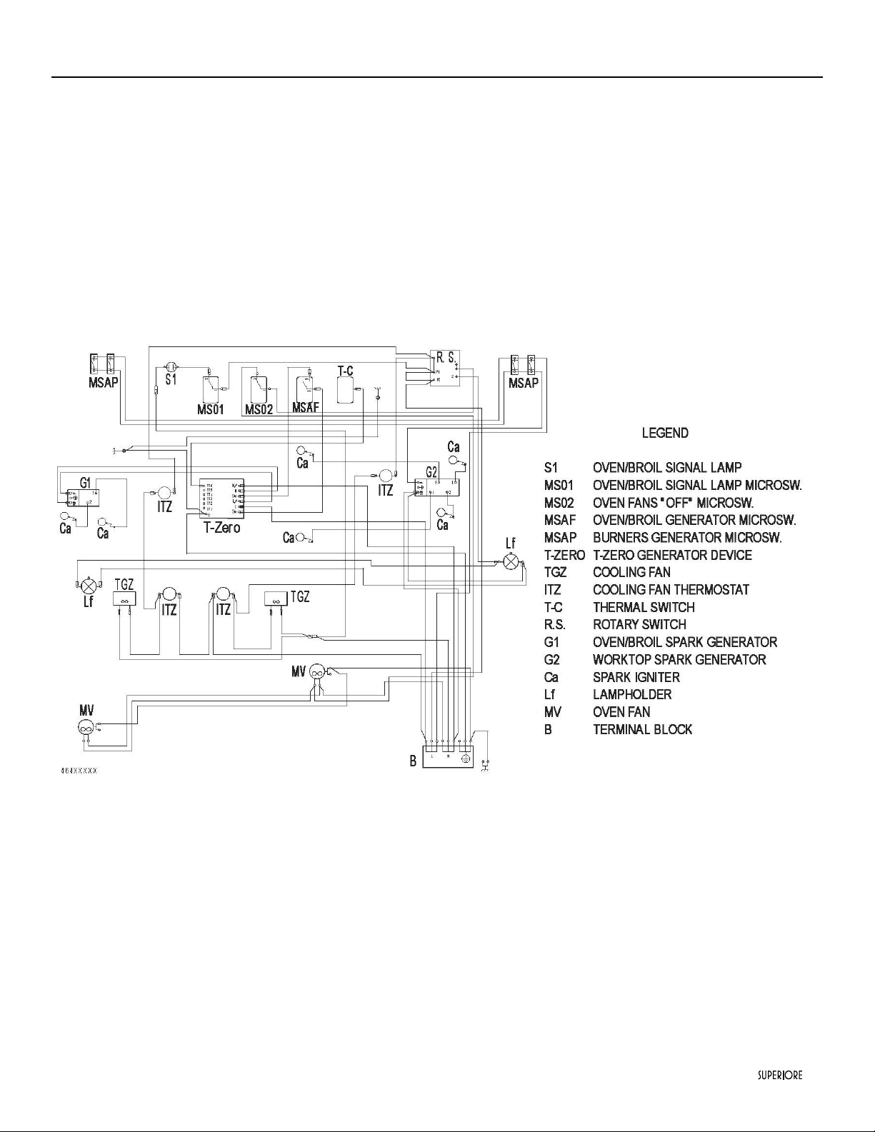
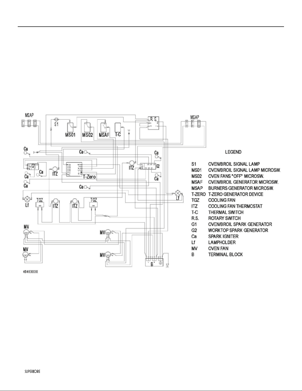
Electric diagram 24” - 30” 4 burners all gas ranges
34
|
Electric diagram 36” 6 burners all gas ranges
|
35
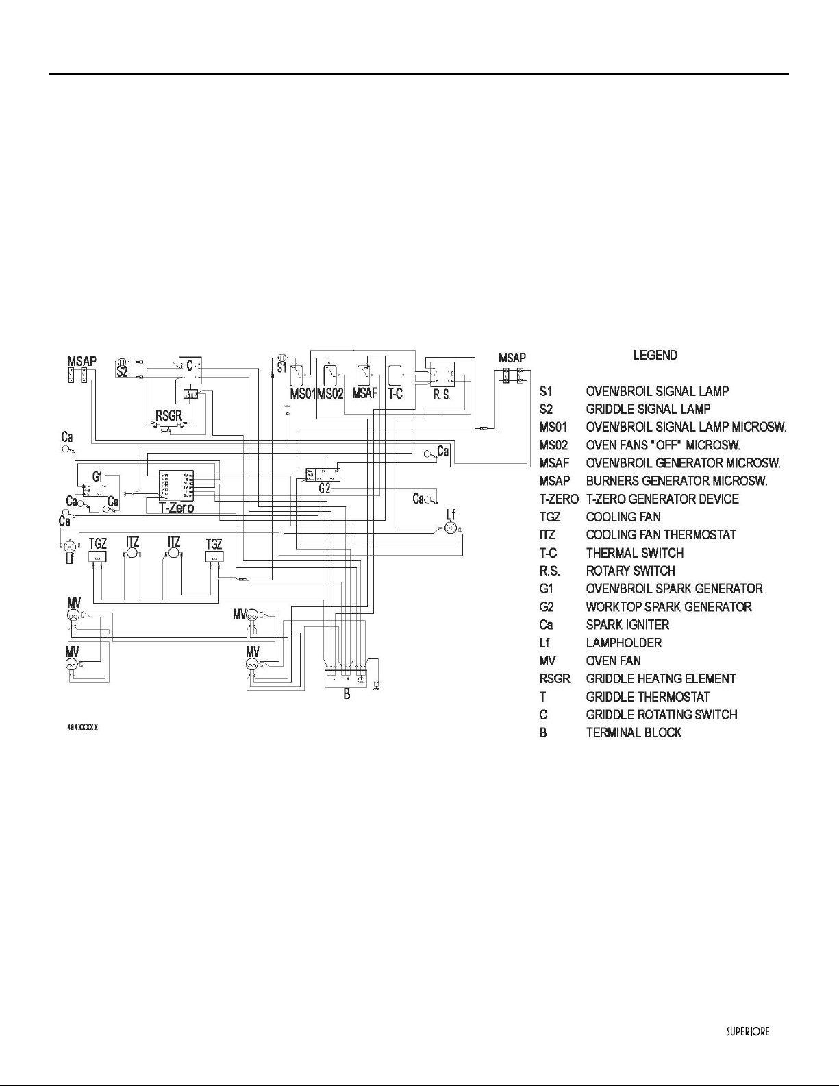
Electric diagram 36”4 burners and griddle all gas ranges
36
|
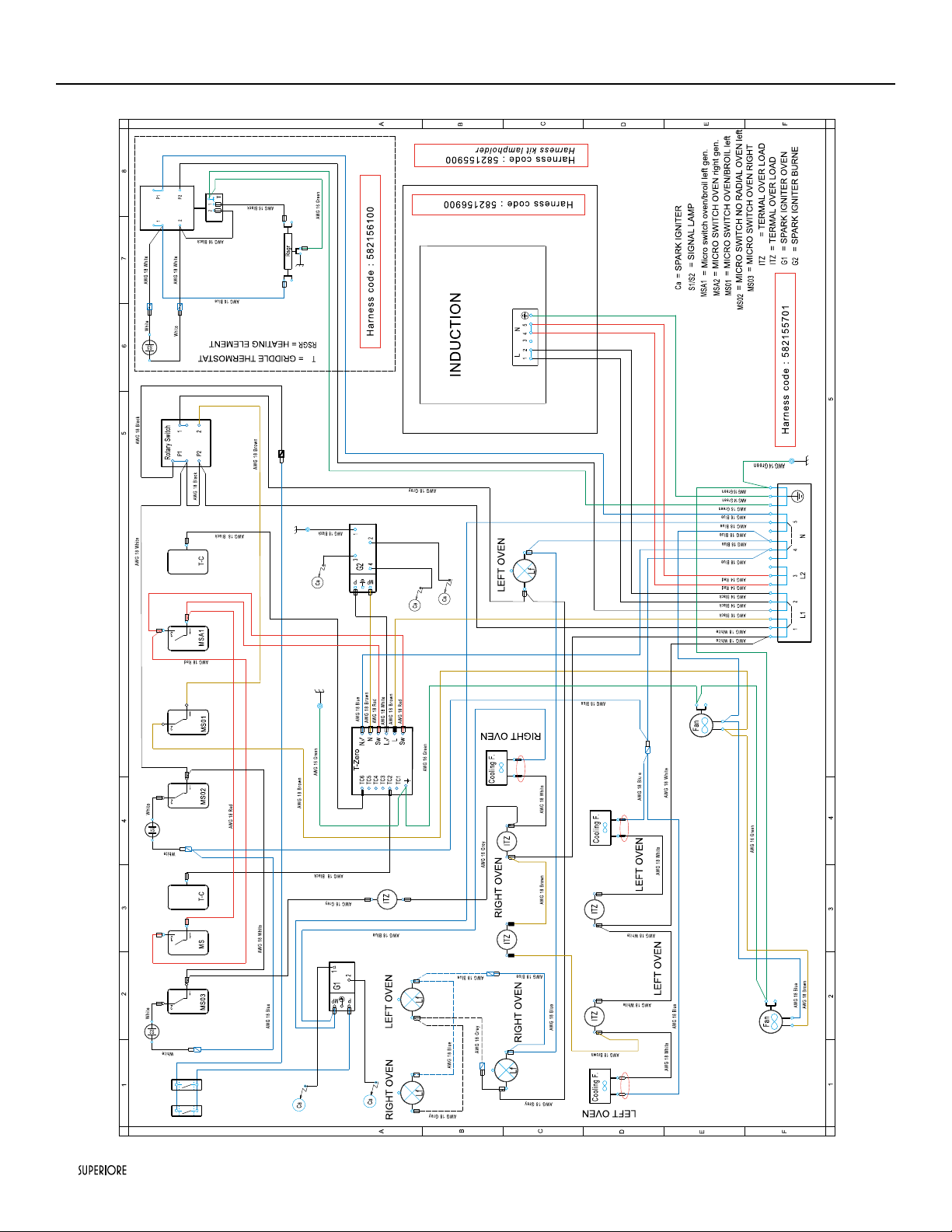
Electric diagram 48” 4 induction areas, electric griddle and 2 gas burners
|
37
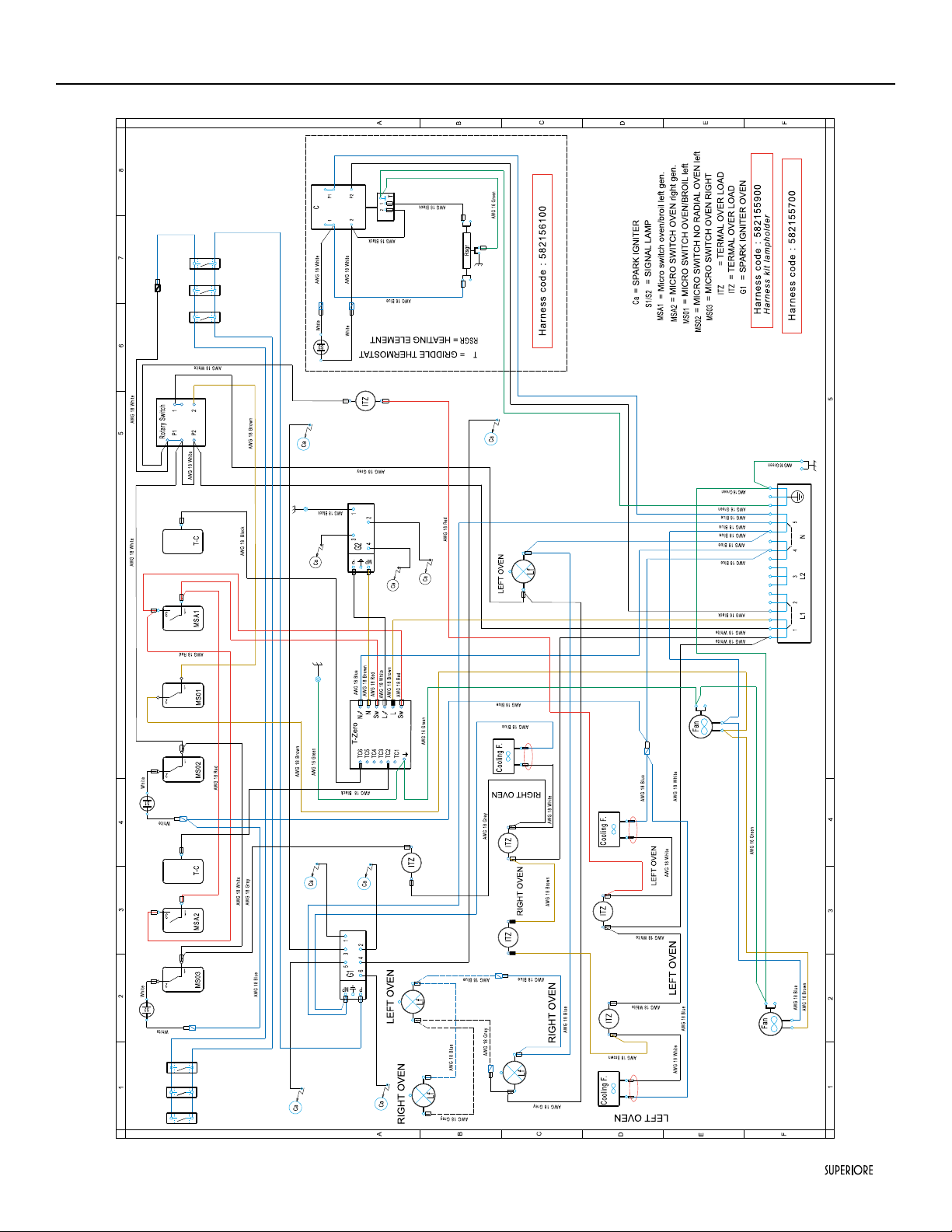
Electric diagram 48” 6 gas burners and electric griddle all gas ranges
38
|
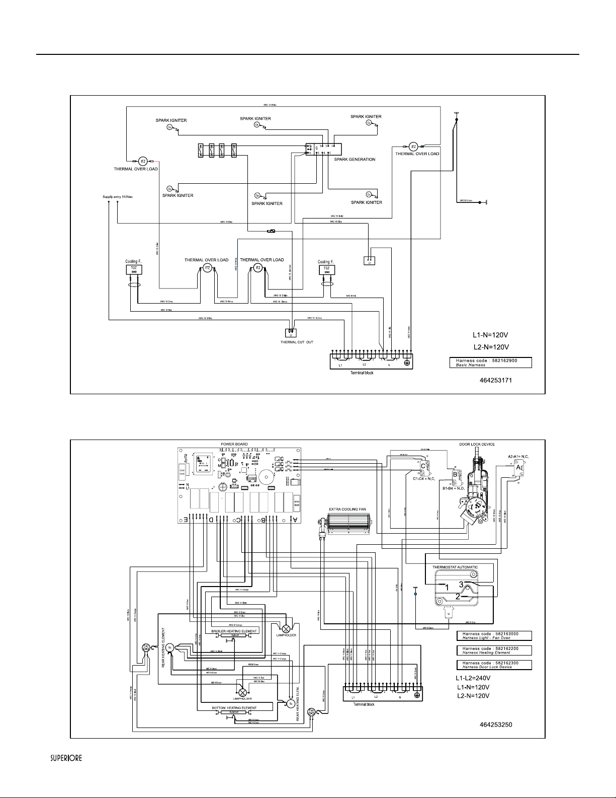
Electric diagram 30” 4 burners dual fuel s.c. ranges
Worktop
Oven
|
39
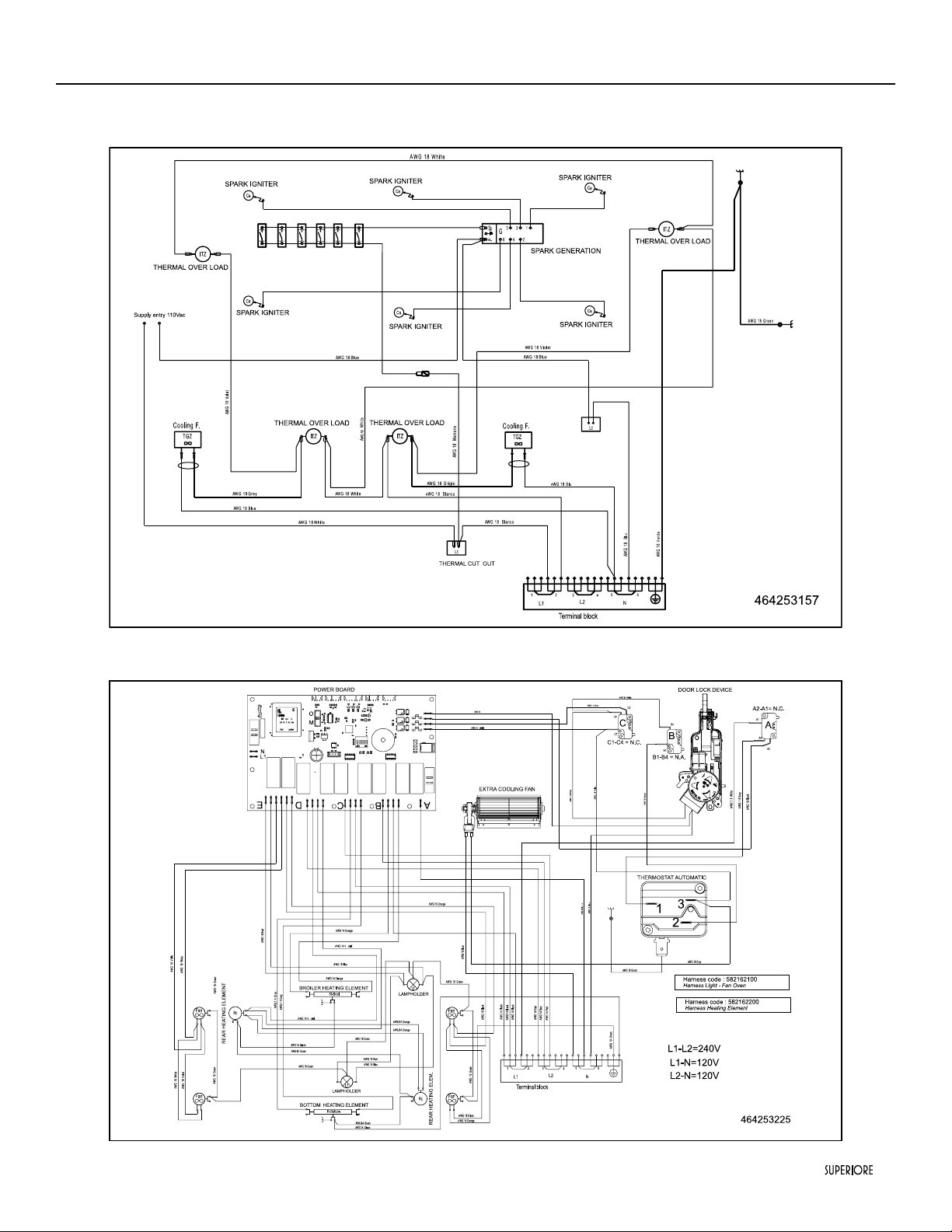
Electric diagram 36” 6 burners dual fuel s.c. ranges
Worktop
Oven
40
|
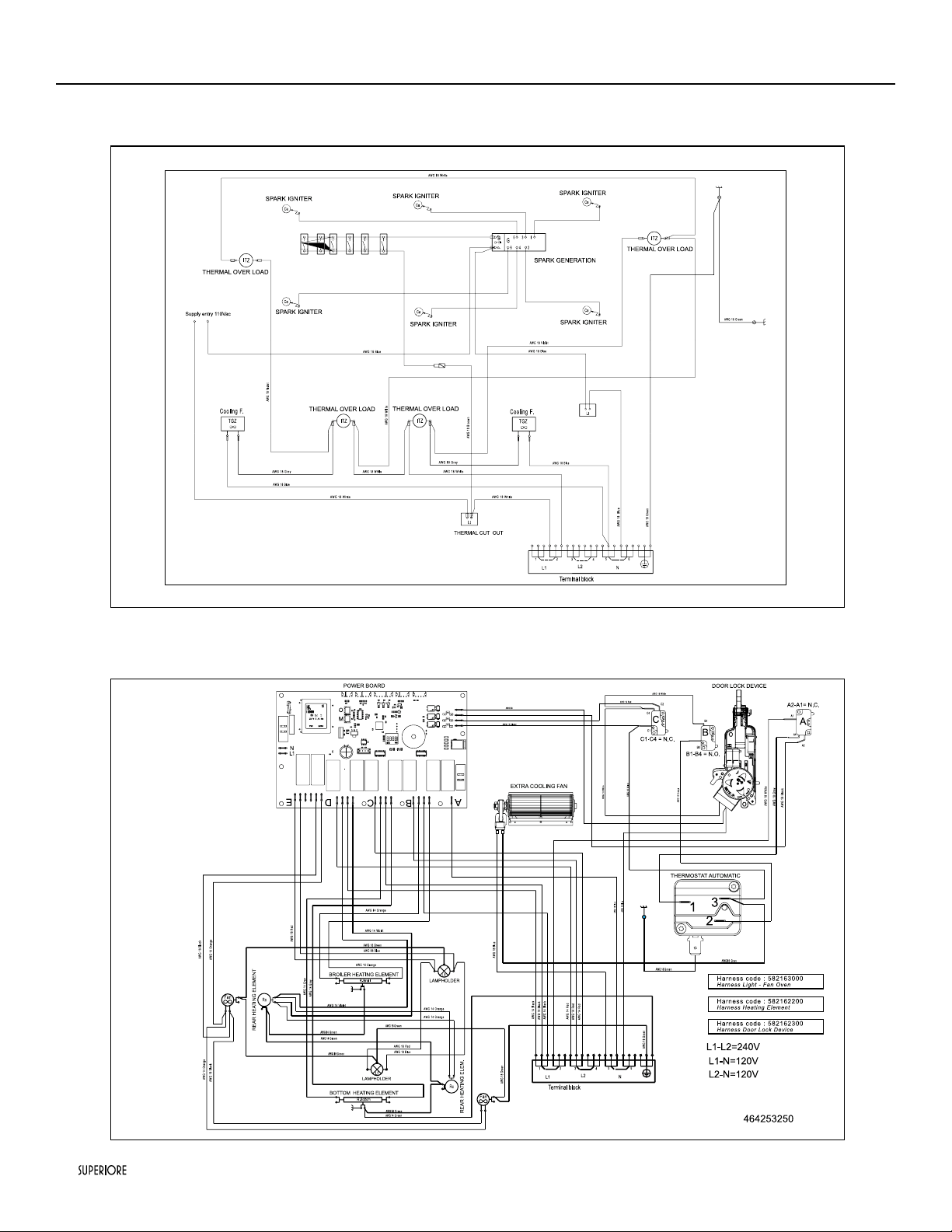
Electric diagram 48” 6 burners and electric griddle dual fuel s.c. ranges
Worktop
Main Oven
|
41
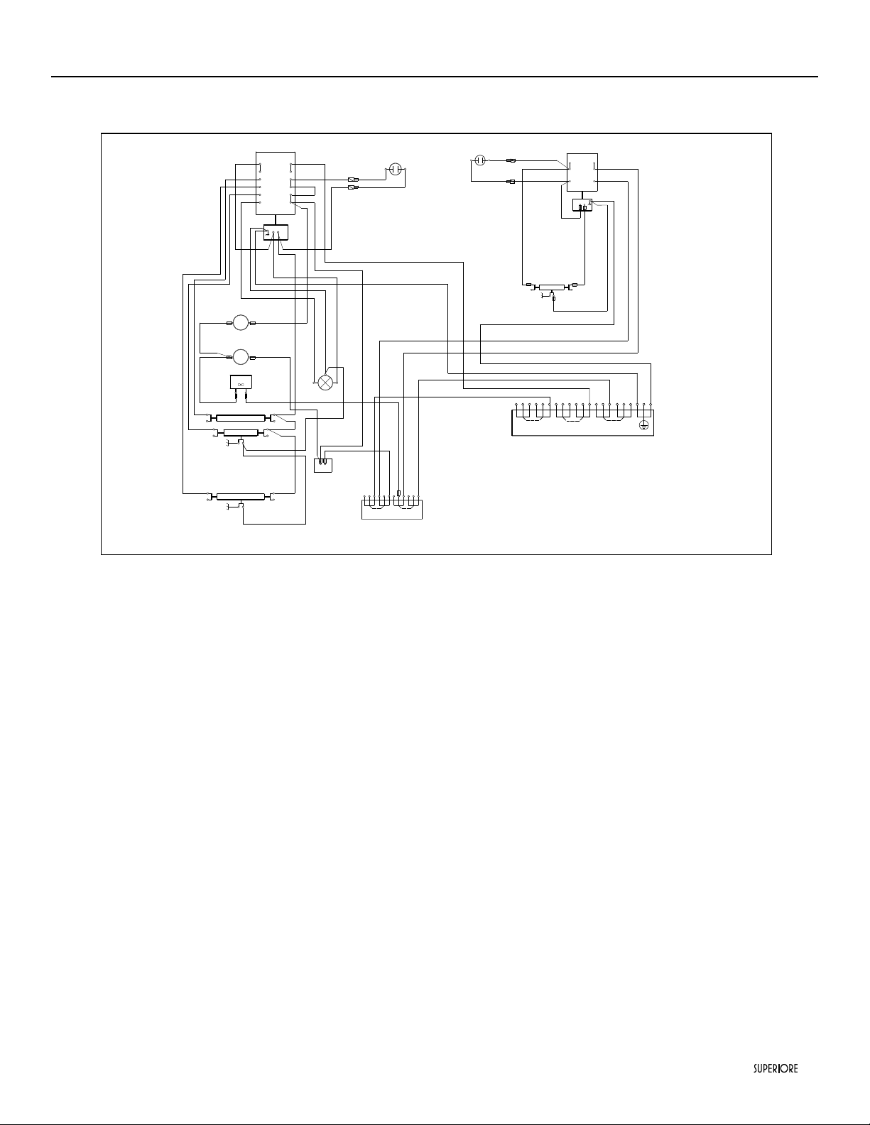
Electric diagram 48” 6 burners and electric griddle dual fuel s.c. ranges
Aux oven
464253267
T
Cordiali saluti
Angelo Capiluppi
AWG18
Wh it e
A WG 1 8 Blu e
A WG18 Re d
AWG18 R ed
A WG 18 G r e e n
A WG18 Blac k
AWG18 Bl a ck
A WG 18 Gre y
Wh it e
A WG 18 Br oo wn
R-Broil
S 1
L
N
Lf
5
4
3
2
P2
P3
2
1
1
C
P1
T
Lt
RIGHT OVEN
TGZ
Wh it e
A WG18 B lu e
A WG18 V iol et
T
Cordiali saluti
Angelo Capiluppi
A WG 18 O r an ge
T
Cordiali saluti
Angelo Capiluppi
I T Z
AWG18 G reen
AWG18 G reen
A WG 18 W hi te
A WG18 Black
A WG 18 B lu e
A WG 18 W hite
A WG 1 8 Blu e
AWG 18 Wh it e
1
2
3
4
L1
N
A WG 18 W hi te
AWG18 Gr een
TERMOSTAT SIGNAL LAMP
R-T
TOP HEATING ELEMENT
BROILER HEATING ELEMENT
R-Bottom
BOTTOM HEATING ELEMENT
THERMAL CUT OUT
THERMAL OVER LOAD
Swich Oven
P 2
2
1
2
P1
C
T
1
Rgr
W hite
W hite
S 2
AW G 18 W hite
AW G 18 W hite
A WG 16 Blu
e
A WG 16 B lack
AWG 16 G reen
AW G 16 Blu e
AWG 16 Black
A WG 16 G r een
A WG 16 B lack
T
Cordiali saluti
Angelo Capiluppi
SIGNAL LAMP
Swich Griddle
HEATING ELEMENT
I T Z
THERMAL OVER LOAD
A WG 18 W hi te
A WG18 V iol et
Terminal block n.2
AWG 18 G reen
AWG 18 G reen
1
2
3
5
4
L1
N
L2
6
Terminal block n.1
AW G 1 8 Bl ue
AW G 1 8 R ed
T
Cordiali saluti
Angelo Capiluppi
AWG18 W hit e
42
|
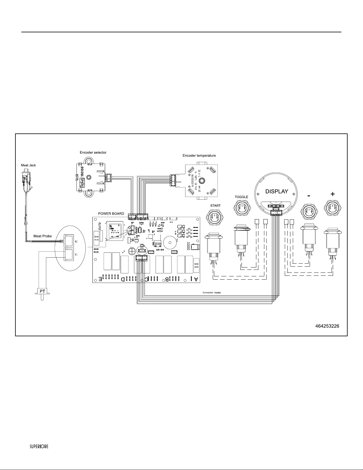
Electric diagram 30’’/36”/48” dual fuel s.c. ranges
Oven

TECNO, S.P. 63R n. 111, 42044 Gualtieri (RE), Italy
T. +39 0522 222 161
appliances are proudly designed and handcrafted in Gualtieri, Italy
Tecnogas Tecnogas Superiore and Superiore are registered trademarks of TECNO

superiore.us
superiore.ca
461308626 - rev 002 10/2017