Loading ...
Loading ...
Loading ...
10
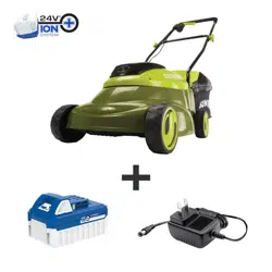
2. Check that the mains voltage is the same as that marked
on the rating plate of the battery charger. Then, plug the
charger adapter into an appropriate AC power outlet.
Connect the charger plug into the charge socket of the
battery to start charging (Fig. 2).
3. The battery will take approximately 2 hours 40 mins
to charge. The battery indicator LEDs will twinkle and
illuminate one by one during the charging process.
Unplug the charger immediately when the 3 LEDs are all
illuminated.
mCAUTION! FIRE HAZARD. When disconnecting the
charger from the battery, be sure to unplug the charger from
the outlet rst, then disconnect the charger from the battery.
mWARNING! This charger does not automatically turn o
when the battery is fully charged. Please take care not to leave
the battery plugged into the charger. Switch o or unplug the
charger at the mains when charging is complete.
4. Timely recharging of the battery will help prolong the
battery's life. You must recharge the battery pack when
you notice a drop in the equipment's power.
IMPORTANT! Never allow the battery pack to become fully
discharged as this will cause irreversible damage to the battery.
Assembly
m
WARNING! Do not insert the safety key until assembly
is complete. Failure to comply could result in accidental
starting and serious personal injury.
mWARNING! Before performing any maintenance, make
sure the key is removed from the unit. Failure to heed this
warning could result in serious personal injury.
mWARNING! The product must be fully assembled
before operation. Do not use a product that is only partially
assembled or assembled with damaged parts.
NOTE: Before using the mower, follow these instructions to
assemble the handle and grass bag.
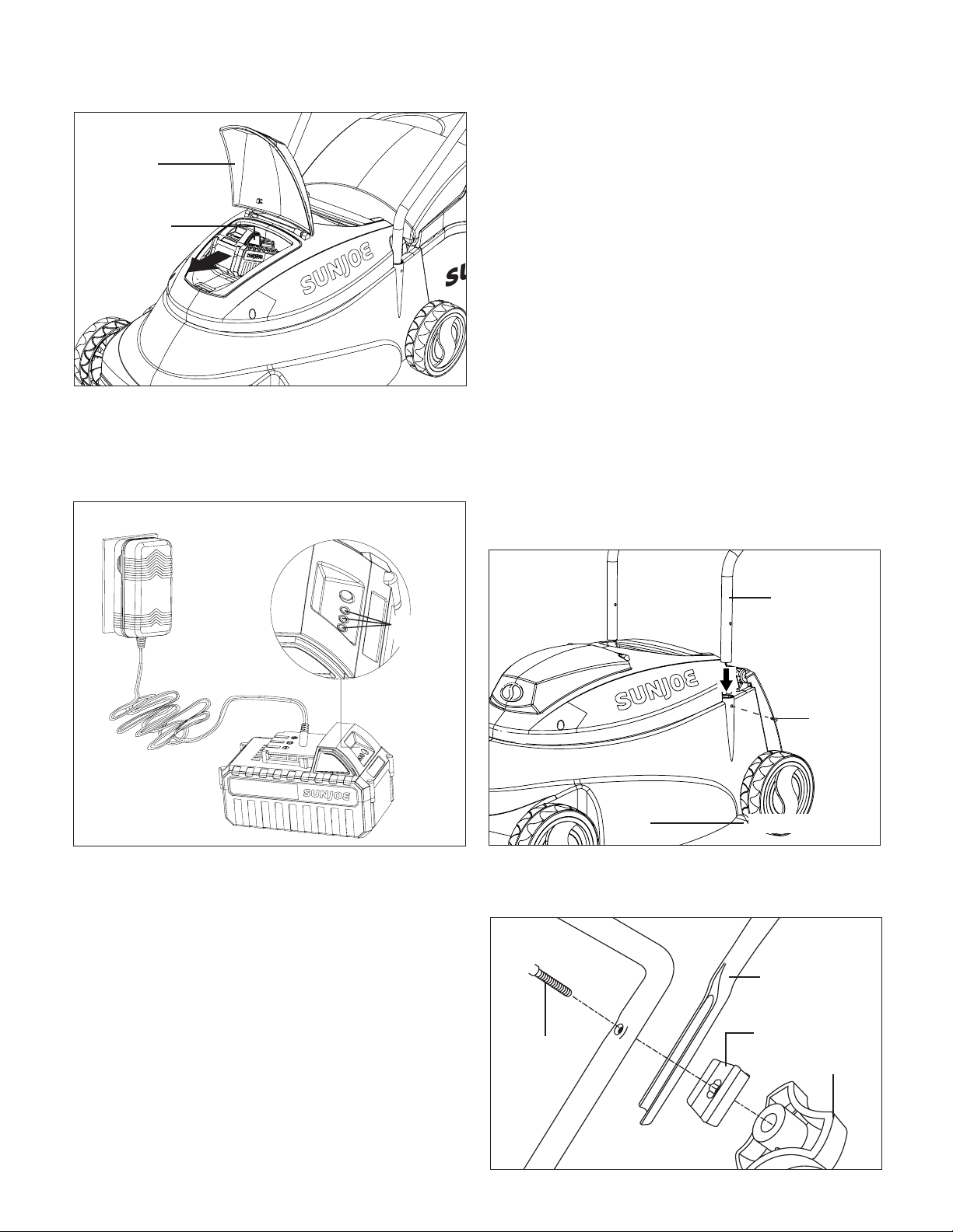
Handle Assembly
1. Fit the lower handle frame into the two holes in the
machine body and fasten the handle on both sides with
the screws provided (Fig. 3).
2. Join the upper handle frame to the lower handle frame
using the knob, washer and bolt provided (Fig. 4). Repeat
on the opposite side.
R
Fig. 1
Battery
compartment
cover
Push lock
button
Fig. 2
Battery
indicators
Fig. 3
Machine body
Screw
Lower handle
frame
Fig. 4
Upper handle
Washer
Knob
Bolt
Loading ...
Loading ...
Loading ...