Loading ...
Loading ...
Loading ...
12
1. Insert the drain hose (accessory) into the drain port (insertion margin: 25 mm
[1 in]).
(The drain hose must not be bent more than 45° to prevent the hose from break-
ing or clogging.)
(Attach the hose with glue for the hard vinyl chloride pipe, and fix it with the band
(accessory).)
2. Attach the drain pipe (O.D. ø32 mm [1-1/4 in] PVC TUBE, field supplied).
(Attach the pipe with glue for the hard vinyl chloride pipe, and fix it with the band
(accessory).)
3. Perform insulation work on the drain pipe (O.D. ø32 mm [1-1/4 in] PVC TUBE)
and on the socket (including elbow).
4. Check the drainage. (Refer to [Fig. 6-13])
5. Attach the insulating material (accessory), and fix it with the band (accessory) to
insulate the drain port.
[Fig. 6-11] (P.4)
A Indoor unit
B Pipe cover (60 mm [3/8 in]) (accessory)
C Tie band (accessory)
D Visible part
E Insertion margin
F Drain hose (accessory)
G Drain pipe (O.D. ø32 mm [1-1/4 in] PVC TUBE, field supplied)
H Insulating material (field supplied)
I Tie band (accessory)
J Max.180 ± 5 mm [7-3/32 ± 7/32 in]
K No gap. The joint of the insulation material must meet at the top.
6. Refrigerant piping work
[Drainage by gravity]
1. Insert the drain hose (accessory) into the drain port.
(The drain hose must not be bent more than 45° to prevent the hose from breaking
or clogging.)
The connecting part between the indoor unit and the drain hose may be discon-
nected at the maintenance. Fix the part with the accessory band, not be adhered.
2. Attach the drain pipe (O.D. ø32 PVC TUBE, field supplied).
(Attach the pipe with glue for the hard vinyl chloride pipe, and fix it with the band
(accessory).)
3. Perform insulation work on the drain pipe (O.D. ø32 PVC TUBE) and on the socket
(including elbow).
6.6. Confirming drain discharge
ss
ss
s Make sure that the drain-up mechanism operates normally for discharge
and that there is no water leakage from the connections.
• Be sure to confirm the above when in heating operation.
• Be sure to confirm the above before ceiling work is done in the case of a new
construction.
1. Remove the water supply port cover on the same side as the indoor unit piping.
2. Fill water into the feed water pump using a feed water tank. Be sure to put the end
of the pump or tank in a drain pan. (If the insertion is incomplete, water may flow
over the machine.)
3. Perform the test run in cooling mode, or turn on the switch SWE on the controller
circuit board. (The drain pump and the fan are forced to operate without any re-
mote controller operation.) Make sure using a transparent hose that drain is dis-
charged.
4. After confirmation, cancel the test run mode, and turn off the main power.
When
the switch SWE has been turned on, turn it off, and attach the water supply port
cover into its original position.
[Fig. 6-13] (P.4)
A Insert pump's end 2 to 4 cm [13/16 to 1-19/32 in].
B Remove the water supply port.
C About 2000 liters
D Water
E Filling port
F Screw
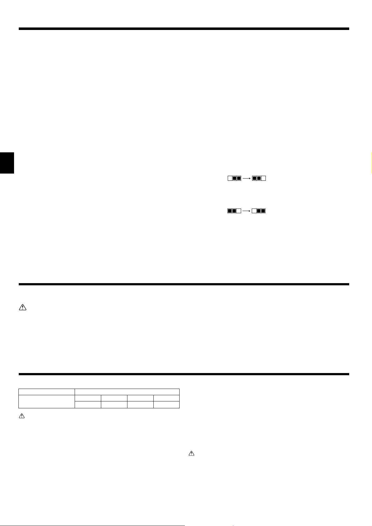
[Fig. 6-14] (P.4)
<Indoor board>
SWE SWE
ON OFF ON OFF
SWE SWE
ON OFF ON OFF
[Fig. 6-12] (P.4) * Drainage by gravity
A Indoor unit
B Pipe cover (30 mm [3/16 in]) (accessory)
C Tie band (accessory)
D Band fixing part
E Insertion margin
F Drain hose (accessory)
G Drain pipe (O.D. ø32 PVC TUBE, field supplied)
H Insulating material (field supplied)
I Max. 145 ± 5 mm
7. Duct work
• When connecting ducts, insert a canvas duct between the main body and the duct.
• Use non-combustible duct components.
Caution:
• The sound from the intake will increase dramatically if intake
AA
AA
A is fitted
directly beneath the main body. Intake
AA
AA
A should therefore be installed as
far away from the main body as possible.
Particular care is required when using it with bottom inlet specifications.
• Install sufficient thermal insulation to prevent condensation forming on
outlet duct flanges and outlet ducts.
•To connect the air conditioner main body and the duct for potential equali-
zation.
• The distance between the inlet grille and the fan should be at least over 850
mm [33-15/32 in] or more.
If it is less than 850 mm [33-15/32 in], install a safety guard so the fan can-
not be easily accessed.
[Fig. 7-1] (P.5)
A Air inlet
B Air outlet
C Access door
D Ceiling
E Canvas duct
F Air filter
G Inlet grille
8.1. Power supply
Electrical specification Input capacity Main Switch/Fuse (A)
Power supply SEZ-KD09 SEZ-KD12 SEZ-KD15 SEZ-KD18
(1 phase ~/N, 208/230V, 60Hz)
10 10 20 20
Warning:
• The compressor will not operate unless the power supply phase connection
is correct.
• Ground protection with a no-fuse breaker (ground leakage breaker) is usu-
ally installed for
DD
DD
D.
• The connection wiring between the outdoor and indoor units can be extended
up to a maximum of 50 m [164 ft], and the total extension including the crosso-
ver wiring between rooms is a maximum of 80 m [262 ft].
Provide switch with at least 3 mm [1/8 in] contact separation in each pole.
* Label each breaker according to purpose (heater, unit etc.).
[Fig. 8-1] (P.5)
A Indoor unit B Outdoor unit
C Wired remote controller D Main switch/fuse
E Ground wire
8.2. Indoor wire connection
Work procedure
1. Remove two screws to detach the electric component cover.
2. Route each cable through the wiring intake into the electric component box. (Pro-
cure power cable and in-out connecting cable locally and use remote control cable
supplied with the unit.)
3. Securely connect the power cable and the in-out connecting cable and the remote
control cable to the terminal blocks.
4. Secure the cables with clamps inside the electric component box.
5. Reattach the electric component cover.
• Attach power supply cable and indoor/outdoor cable to control box by using buffer
bushing for tensile force. (PG connection or the like.)
Warning:
• Attach the electrical part cover securely. If it is attached incorrectly, it could
result in a fire or electric shock due to dust, water, etc.
• Use the specified indoor/outdoor unit connecting wire to connect the indoor
and outdoor units. Attach the wire to the terminal block securely so that stress
is not applied to the terminal block connection. Incomplete connection or
fixing of the wire could result in a fire.
8. Electrical work
Loading ...
Loading ...
Loading ...