Loading ...
Loading ...
Loading ...
11
Installing/Replacing Guide Bar +
Cutting Chain
mWARNING! Always wear heavy-duty gloves when
handling the bar and chain. Mount the bar and chain very
carefully so as not to impair the safety and eciency of the
machine. If in doubt, contact an authorized Snow Joe
®
+
Sun Joe
®
dealer or call the Snow Joe
®
+ Sun Joe
®
customer
service center at 1-866-SNOWJOE (1-866-766-9563).
NOTE: When replacing the guide bar and chain, use only
identical replacement parts. Make sure the pole chain saw
is disconnected with the battery before proceeding with
installation.
NOTE: When you rst purchase your chain saw, the chain
will come separately in the chain + bar box. Refer only to the
instructions for tting the chain and bar (from step 5). Should
you need to replace the chain and bar in the future, follow all
the steps detailed below.
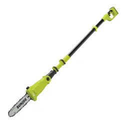
1. Unscrew the end cover knob counterclockwise to unlock
and remove the chain/sprocket end cover (Figs. 4 to 5).
2. Remove the bar and chain from the mounting surface
(Fig. 6).
3. Remove the old chain from the bar.
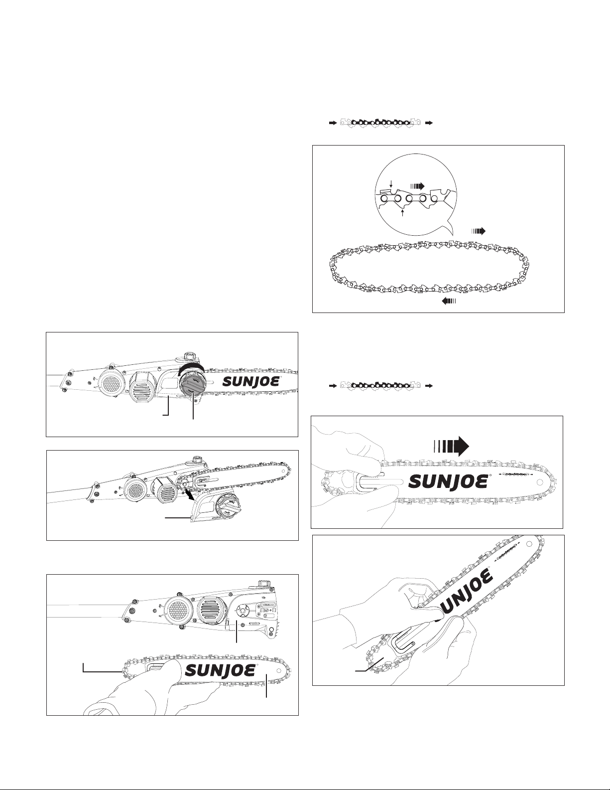
4. Lay out the new saw chain in a loop and straighten
any kinks. THE SHARP SIDE OF THE TEETH MUST
FACE AWAY FROM YOU IN THE DIRECTION OF THE
CHAIN ROTATION INDICATED ON THE GUIDE BAR
. If the teeth face backwards,
turn the loop over (Fig. 7).
5. Starting at the tip, mount the chain drive links into the
bar groove, leaving a loop at the back of the bar. The
chain will loosely t until it is placed on the sprocket
(Figs. 8 – 9).
NOTE: Make certain of the direction of the chain
. If the chain is mounted
backwards, the saw will vibrate abnormally and will not
cut.
6. Hold the chain in position on the bar and place the loop
around the sprocket. Fit the bar ush against the mounting
surface so that the bar stud hole are aligned with the long
slot of the bar (Fig. 10).
R
Chain/sprocket
end cover
Fig. 4
End cover knob
Chain/sprocket
end cover
Fig. 5
R
Guide bar
Fig. 6
Cutting chain
Mounting surface
Chain rotation
Sharp cutting edge
Chain drive link
Fig. 7
R
Fig. 8
R
Loop
Fig. 9
Loading ...
Loading ...
Loading ...