Loading ...
Loading ...
Loading ...
10
ENGLISH
(Original instructions)
J6 FILTERSENSOR
Smart sensor technology automatically detects (the symbol will light red)
when the lter becomes clogged and needs to be cleaned.
Note: The FILTERSENSOR LED will flash and the unit will
automatically shut down when there is any obstruction in the
flexible hose or filters which is causing the motor to overheat.
Disconnect and remove the blockage immediately.
Using the handle / wand (Fig. B, C, D, E)
u Press the handle / wand release button (11) to free the
handle / wand (3) from the chassis (12).
u Free the hose connector (9) from the chassis hose port
(13) as shown in gure B.
u Press the chassis release button (12a) to release the lift
away cannister vac (5) from the chassis (12) as shown in
gure C.
u Connect the hose connector (9) to the exible tube port
(3a) ensuring that the latch (9a) clicks securely into place
as shown in gure D.
u Extend the crevice tool (4) as shown in gure E, until it
clicks in place.
u To retract the crevice tool (4) press the tube extension
latch (3b) allowing it to return to its normal position.
Using the 3-in-1 accessory tool (Fig. F)
u The 3-in-1 handle / wand (15) has three congurations.
1. Brush mode.
2. Small crevice mode.
3. Upholstery mode.
u The 3-in-1 handle / wand can be tted either directly to the
hose connector 9 or to the extendable crevice tool (4) as
shown in gure F.
Removing and clearing the beater bars
(Fig. G, H)
u To remove the beater bar cassette (14a) from the oor
head (14) Depress the release button (14b) as shown in
gure G.
u The beater bar (18) can now be removed.
The end pieces are also removable allowing you to clear
the brushes from any hair or other debris that may have
accumulated as shown in gure H.
Note: The CUA525BHP unit is supplied with a specialised pet
beater bar (18a) for cleaning pet hairs etc.
Charging (Fig. I)
u Place the appliance into the charging base (7) as shown in
gure I .
u Plug the charging base (7) into an electrical outlet.
u Switch the electrical outlet on. The LED charging indicator
will ash and increase in sections.
LEDs go out when fully charged.
Note: The Charging base is supplied with 2 screws and wall
plugs for securing it to a wall, providing extra stability, as
shown in gure I.
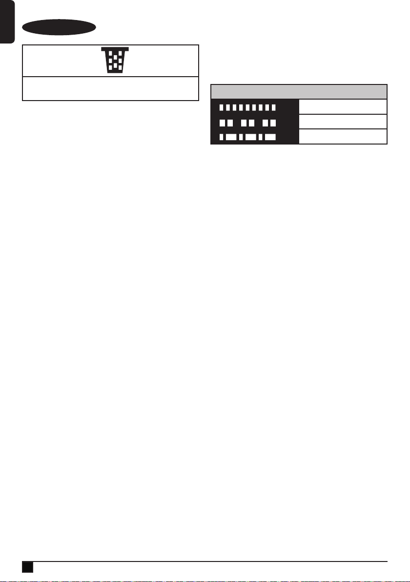
Battery Sensor LED Patterns
Battery Fault (All LEDs)
Charger Fault (All LEDs)
Battery Hot (All LEDs)
Battery diagnostics
If the appliance detects a weak battery, the charging indicator
will ash at a fast rate when the power button is activated.
Proceed as follows:
u Plug in the charger. Switch on at the mains.
u Leave the appliance to charge.
If the appliance detects a damaged battery, the charging
indicator will ash at a fast rate when the appliance is on
charge. Proceed as follows:
u Take the appliance and the charger to be tested at an
authorised services centre.
Note: It may take as long as 60 minutes to determine that
the battery is defective. If the battery is too hot or too
cold, the LED will alternately blink, fast and slow, one
ash at each speed and repeat.
Emptying the dust bowl (Fig. K, L, N)
u Holding the unit over a suitable waste receptacle, press
the dust bowl release button (6a) to release the dust bowl
lid (6) as shown in gure K.
u Push the compacting handle (19) down to empty the
contents of the dust bowl (5a) as shown in gure L.
Compacting the contents of the dust bowl
(Fig. M, N)
u With the dust bowl lid (6) closed, push the compacting
handle down to compact the contents of the dustbowl (5a)
thus increasing its capacity as shown in figure N.
N1 = Before compacting. N2 = After compcting.
Releasing the dust bowl (Fig. O, P)
Note: The dust bowl can be released either from the unit while
it is in chassis mode, as shown in gure O, or when being
used in the lift away canister vac mode, as shown in gure P.
u Press the dust bowl release lever (20) down to release the
dust bowl.
u Free the dust bowl (5a) from the lift away canister vac (5).
Note: The catch (20a) ensures that the unit will be unable to
start when the dust bowl (5a) is not connected to the lift away
canister vac (5) or when the compacting handle (19) is in
operation.
Loading ...
Loading ...