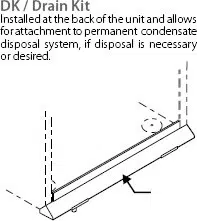
INSTALLATION INSTRUCTIONS
FOR DC-2 DRAIN KIT
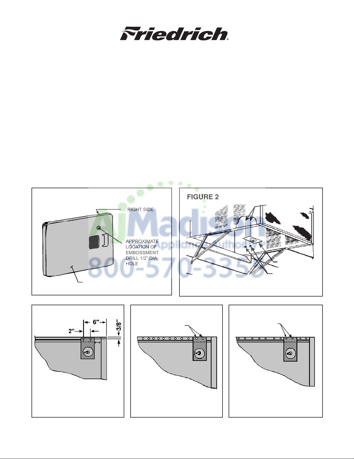
STEP 1 Before sliding chassis into outer shell, turn chassis on its side and add drain hole by drilling
½” diameter hole as shown in Figure 1.
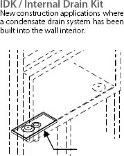
STEP 2 DC-2 mounts to the bottom of the outer shell as shown in Figure 2 on the right side as you face
the unit. Use two (2) 10 - 24 x 3/8” long machine screws and 10 - 24 hex nuts provided.
STEP 3 SQ, KQ, YQ Models - Drill two ¼” holes in outer shell as shown in Figure 3. Also drill a 3/8”
diameter hole in the base pan 3½” from the back and 3½” from right side.
STEP 4 Small and Medium Chassis Models - Mount in second and third holes from the rear of shell;
See Figure 4.
STEP 5 Large Chassis Models - Mount in third and fourth holes from the rear of shell; see Figure 5.
STEP 6 Connect a suitable length of garden hose or other tubing to end of the drain tube to drain the
condensate away.
FIGURE 1 FIGURE 2
FIGURE 3
FIGURE 4 FIGURE 5
RIGHT SIDE
APPROXIMATE
LOCATION OF
EMBOSSMENT.
DRILL 1/2” DIA.
HOLE
BACK OF BASE PAN
10-24X 3/8” LONG
SCREWS
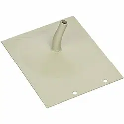
DRAIN PLATE
10X24 NUTS
SQ, KQ, YQ MODELS
BOTTOM VIEW
SMALL & MEDIUM
CHASSIS MODELS
BOTTOM VIEW
LARGE
CHASSIS MODELS
BOTTOM VIEW
2ND & 3RD HOLES
FROM REAR OF
SHELL
3RD & 4TH HOLES
FROM REAR OF
SHELL
1900235 (11-05)